Tasmota: Add support for SM2135 as used in Action LSC SmartLed
Extend Tasmota with support for SM2135 five channel intelligent dimmer led with constant current driver interfaced using I2C as used in Action LSC Smart Leds (https://www.action.com/nl-nl/p/lsc-smart-connect-slimme-multicolor-ledlamp-2/)
SM2135E_zh-CN_en-US_translated.pdf
See https://www.mikrocontroller.net/topic/479796#5950544 for background info.
 arendst
All 75 comments
Great since there are many Shops in Europe :-)

 Jason2866
on 26 Sep 2019
Jason2866
on 26 Sep 2019
VERY EXPERIMENTAL as I have many questions using the current documentation.
I currently fail to flash these bulbs so I cannot test it yet.
In order to use it you will need to add define USE_SM2135 to my_user_config.h or your override file.
arendst
on 26 Sep 2019
Great work arendst! I dumped the firmware of the E14 bulb so maybe there is a chance tuya-convert will be compatible soon. I'll test your experimental driver (_probably sunday evening_) and report my findings.
Have to find a 15v psu first I guess, that's printed on the LED circuit board but I suppose 12v will due as well🤔
EDIT: Any specific information you want me to test? I noticed in the datasheet that RGB cannot be used simultaneously with W/YW?
 TimelessNL
on 27 Sep 2019
TimelessNL
on 27 Sep 2019
From what I read in the spes the address starts from 0xC0 1100 0000
define SM2135_ADDR 0x40
Or did I got that wrong?
 ggaljoen
on 27 Sep 2019
ggaljoen
on 27 Sep 2019
@TimelessNL the 15V and Vin are different.
RGB from 15V and White/warm from Vin. Can you measure that?
ggaljoen
on 27 Sep 2019
mmh interesting... I can try to measure that, but I tried tuya-convert-new-api on my bulb (_in parts_) and guess what? It works just fine. So do we still need to know the voltage since any bulb can now be ota'ed?
Also flashed my bulb with tasmota-dev and tried the experimental SM2135 support.
Unfortunately this does not seem to work quite yet 😢
Results:
- Chip is detected and CW/WW sliders are shown.
- All colors do show but are completely random.
(_command:color 1= red,color 2= green,color 1= any other random color_)
When I set scheme 2 the bulb goes berzerk. It is just flashing random colors together with CW/WW.
UPDATE:
this is the i2c connection settings for the GU10 and E14:

TimelessNL
on 27 Sep 2019
Regarding tuya-convert you just did you use python2 or python3?
I think I have to sacrifice my bulb and try to open it up to find if it still uses the esp8266...
arendst
on 27 Sep 2019
@arendst can we flash ota over and over until we got the i2c driver part right? Is commandline i2c an option? else we need to listen the lsc talking to it.
@TimelessNL my next trail and errors will be after this weekend (drukke agenda)
ggaljoen
on 27 Sep 2019
The fact the chip respons to commands means the I2C address is just fine. All that needs to be done is figuring out the color positions in the string and chip timing.
Ota can be done many times but it makes more sense that I try to get it working as that will solve the issue much quicker.
arendst
on 27 Sep 2019
@arendst not sure if you noticed but I did figure out why 3 different brands of my bulbs didn't work with the new branch of tuya convert. Simply changing the build on my Raspberry Pi from Stretch to Buster fixed it. (Timing issues maybe?) I posted about it in the long thread discussing flashing the bulbs. You might have some luck with yours and not destroy it.
EDIT: Add link - https://github.com/ct-Open-Source/tuya-convert/issues/273#issuecomment-535780741
 digiblur
on 27 Sep 2019
digiblur
on 27 Sep 2019
Thx. I did use Buster on a latest Raspberry Pi but failed. I'll do it over again tomorrow and report.
arendst
on 27 Sep 2019
Regarding tuya-convert you just did you use python2 or python3?
I just installed ubuntu 18.04 on a spare laptop and removed sudo apt-get upgrade -y from install_prereq.sh and ran the script. Some update seem to cause issues to tuya-convert. So I just skipped the upgrade part. This worked fine for me.
Please take note that I use the new-api branch. Only that one works with the GU10 and E14 bulbs.
I think I have to sacrifice my bulb and try to open it up to find if it still uses the esp8266...
You bought the LSC E14 or GU10 bulb right? It would be strange that they manufactured a RTL and ESP version 🤔 because I bought some today and they did contain the ESP like my first sacrificed bulb did.
TimelessNL
on 27 Sep 2019
@TimelessNL do you got an E27 also? Could you triple check that it won't flash, now you got it up and running?
ggaljoen
on 27 Sep 2019
@ggaljoen you disassembled the E27 bulb right? I saw the picture and it shows a Tuya WR3L which according to the datasheet is a RTL8710: User-Manual-4311156.pdf
so no ESP8266 unfortunately.
I could have tested it only if they where in stock, all E27 bulbs in my local area are pretty wanted :laughing:. The WL3L can however be replaced with a ESP (pin compatible) because that's what I did with the siren. But I doubt that is worth it since there are better E27s on the market that are better equipped than 6 5050 style RGB LEDs.
TimelessNL
on 27 Sep 2019
Just got two E14 bulbs and will try to update one and continue work on the driver.
arendst
on 28 Sep 2019
Great. Good luck!
TimelessNL
on 28 Sep 2019
Well flashing went easy using kueblc's new-api version.
Now on to the next phase...
arendst
on 28 Sep 2019
How is the next phase going arendst? Did you find anything interesting?
TimelessNL
on 29 Sep 2019
No luck yet. Had no time today as the shutter needed to get merge.
What I found out so far is that the chip responds with all i2c addresses when scanned - not good. Unable to send anything to the chip. Only tested on pre-2.6.0
Next actions will be
- try core 2.4.2 which has different wire driver
- experiment with i2c stretch time and/or clock rate
- open second device, connect logic analyser using opto couplers to sda/clk and monitor tuya i2c traffic
arendst
on 29 Sep 2019
Ah that's unfortunate. I was using 2.5.2 last time but did not actually scan for adresses. But were you able to get any light out of it? Because my bulb actually produced colors in different brightness levels so your sketch seemed to be able to talk to the chip in some manner.
I will try tomorrow evening to see if I can work out some buspirate magic (been a long time though so I may be a bit rusty). Also something that came to mind, I was looking at the ESP sdk repo from tuya which did not contain that much code. But since the E27 RGB contains the RLT chip and the RTL repo contains many more examples we might find something interesting there, but that's just a guess.
TimelessNL
on 29 Sep 2019
Be carefull with connecting something to the bulb; the gnd is on some level connected to your L or N 230V. As Arendst stated, use opto's to uncouple from the mains wires/voltages! Got the Magic black smoke escaped that way...
My specs remarkable reading was not to have a device address only mentioned a data address, strange.
ggaljoen
on 29 Sep 2019
Thanks for the warning, I've seen your post earlier. That's why I was planning to power the chip from my bench power supply. That makes it even saver for myself to probe this thing.
TimelessNL
on 29 Sep 2019
Progress!!
After a day of rest and re-applying power to the bulb it now responds to color commands. Still no correct relation but at least I have some kind of communication going.
arendst
on 30 Sep 2019
I was trying some experimental writes to this chip and it seems to me that RGB cannot be used with CW. Also on the last page of the datasheet it somewhat states (_in chinglish_)
two groups led Light by MCU Alternate control work, can not work simultaneously.
So I suppose this is different than how Tasmota normally handles RGBCW right?
TimelessNL
on 1 Oct 2019
You're right, Byte 2 selects RGB of WY mode...
 Keeze
on 1 Oct 2019
Keeze
on 1 Oct 2019
Meh that's unfortunate. 😞
I was hoping that byte 2 only selected RGB/YW for that operation and that the other mode stayed on it's last set state.
TimelessNL
on 1 Oct 2019
@arendst small question, where did got the 0x40 for SM2135_ADDRfrom?
Because it does not matter what address I use, it always responds with a random color 😕
TimelessNL
on 1 Oct 2019
The 0x40 comes from the datasheet you provided. It documents addresses from 0xC0 to 0xC6. As I2C device addresses are ALWAYS from 0x01 to 0x7F the correct addresses should be 0x40 to 0x46.
When I do a I2CScan I also see response on all addresses. This means the device most probably does not adhere to the correct I2C specs and implementing it will need special consideration.
In my test environment I had to disable all I2C devices except the SM2135. In the meantime I wrote an extra layer on top of I2C device recognition to handle this phenomenon; Once a SM2135 is recognised all other I2C devices will be disabled.
The main task still lies ahead; the bulb responsw is stil inpredictable as different colors appear with same I2C data send.
Regarding the RGB/CW switch I think that's all to do with power management; to make sure onle one of them is active the power supply can be smaller while still selling RGB/CW functionality. In my test driver this is also anticipated where CW is only allowed when RGB are all set to 0.
arendst
on 2 Oct 2019
When I do a I2CScan I also see response on all addresses. This means the device most probably does not adhere to the correct I2C specs and implementing it will need special consideration.
That's what I also noticed:
[19:17:57][I][i2c:033]: Scanning i2c bus for active devices…
[19:17:57][I][i2c:040]: Found i2c device at address 0x08
[19:17:57][I][i2c:040]: Found i2c device at address 0x09
[19:17:57][I][i2c:040]: Found i2c device at address 0x0A
[19:17:57][I][i2c:040]: Found i2c device at address 0x0B
[19:17:57][I][i2c:040]: Found i2c device at address 0x0C
[19:17:57][I][i2c:040]: Found i2c device at address 0x0D
[19:17:57][I][i2c:040]: Found i2c device at address 0x0E
[19:17:57][I][i2c:040]: Found i2c device at address 0x0F
The main task still lies ahead; the bulb responsw is stil inpredictable as different colors appear with same I2C data send.
Just some considerations from a noob (and I may be talking s*) ;)
I saw that you don't use bit 0? And do you always send the whole command (8bytes), including the RBW / WY switch.
As I interpret the datasheet, you only have to send the required commands and as long as the module is in RGB mode it stays in RGB mode. You use bit 0 to point to the first register you want to change.
So when using all 8 bytes, you also have to send the bytes of the mode, not used.
Also, I don't think you have to set the RGB value to 0 when switching to White mode.
Keeze
on 2 Oct 2019
PROGRESS!!
I managed to take control over the bulb albeit NOT using the wire library. It seems the protocol is a bit different from I2C. My local tweaks allow full control over colors and whites. As some already noticed its either colors OR whites but that should be normal practice anyway.
Now on to finding a way to implement seamlessly with the other light protocols...
arendst
on 4 Oct 2019
Released support for SM2135 using the template below:
{"NAME":"LSC RGBCW LED","GPIO":[0,0,0,0,0,0,0,0,181,0,180,0,0],"FLAG":0,"BASE":18}
Great work! I'll probably visit the Action anytime soon to buy some more bulbs :laughing:
TimelessNL
on 4 Oct 2019
Great job guy's!! So the LSC RGBW LED bulb's with E14 and GU10 socked are flash-able with the new Tasmota firmware and the E27 need a board swap to a ESP one to do the same (right?).
 Xenomes
on 4 Oct 2019
Xenomes
on 4 Oct 2019
Yes, not sure about the E27 though, I can't verify that it has the SM2135 on the pictures I have seem of the PCB.
TimelessNL
on 4 Oct 2019
Wich tasmota firmware are you using?
Development or do you have a binarie?
 haubke
on 4 Oct 2019
haubke
on 4 Oct 2019
@haubke http://thehackbox.org/tasmota/pre-2.6/sonoff.bin
the official source for Tasmota
http://thehackbox.org/tasmota/
Jason2866
on 4 Oct 2019
Closing this issue as it has been added. Thanks.
 ascillato2
on 5 Oct 2019
ascillato2
on 5 Oct 2019
@arendst I just tested your implementation and it indeed works great! Thanks.
One quick observation however. At this moment the I_max for RGB is set to SM2135_20MA but the bulb is rated for 5W. Being the RGB input is 15V * 0.06A the total power draw result in +/-1W.
I know that the chip default is SM2135_20MA for RGB and SM2135_30MA for CW.
But the E14 has:
- 4x RGB
- 8x WW
- 8x CW
And the GU10 has
- 5x RGB
- 8x WW
- 8x CW
That means the current though each individual RGB LED is max 5mA and each inididual CW led is max 4mA. Correct me if I'm wrong but aren't the chip defaults a little conservative? Not tested the heat output though.
TimelessNL
on 5 Oct 2019
I configured it conservative indeed. I had an overtemp shutdown with CW set to 20mA. The chip powers off at 85 C.
I had planned to do some measurements comparing the tasmota bulb with a tuya bulb but I couldn't find a second E14 socket in time.
Feel free to experiment and let us know to correct equilibrium between lumen and temperature.
NB. I suggest you read the sm2125 datasheet regarding current calculations.
arendst
on 5 Oct 2019
Hi, just want to say LSC GU10 is working.
Flashing with the new master on a Rapi 3 Buster lite, using the Tasmota 6.6.0.15 as firmware
Also working "Etersky EU Socket"
Thanks to all who make it possible.
 EddyDsSmartHome
on 5 Oct 2019
EddyDsSmartHome
on 5 Oct 2019
Hi, i managed to get the GU10 flashed with latest Tasmota (and only had one panic attack when my router did not assign a IPv4 but only a v6). After searching in the templates it dawned to me that i still had to add a custom one. (just writing this here for the next one).
Is support for the RGB LEDs planned to? (edit: just saw that they work in Home Assistant. I didn't know that. Just was refering to the html-frontend)
 oopsitsaflame
on 6 Oct 2019
oopsitsaflame
on 6 Oct 2019
I'm a bit confused: I read that the E14 and the GU10 can now work using Tasmota, but is the E27, which specifically mentioned in the start-post now also flashable?
 FransTwisk
on 9 Oct 2019
FransTwisk
on 9 Oct 2019
No, the E27 is not supported as it it does not contain an ESP8266.
arendst
on 9 Oct 2019
Thanks for the clarification.
FransTwisk
on 9 Oct 2019
I've added the compatible LSC bulbs to the tuya-convert wiki
I successfully flashed 5x E14's & 4x GU10's with Tasmota 6.6.0.15 (_including sm2135 support_) and they all worked perfectly.
Except for 1 stubborn GU10 ...
I have no clue to why that one does not work, it did have one broken CW LED out of the box so that may have something to do with it. If I use the 'old' driver it behaves exactly the same as any other SM2135. But when I use the newer driver it seems to work for a while (_RGB scheme2_) then freezes, then continue to work, then stops completely and after several minutes continues normal operation after which the cycle repeats. Very strange... The white colors are a completely different story, they work after initial power-up but then completely ignores future commands, and a long power cycle is needed to restore operation. I don't think it's a driver issue as for now, since 9 other bulbs are working just fine.
I removed the plastic cap (_very easy btw, no glue_) to see if I could spot any manufacturing defect. But everything seemed normal.

TimelessNL
on 9 Oct 2019
Mhh, behaviour could be a power issue. Looks like overheating
Jason2866
on 10 Oct 2019
Power issue is feasable. But overheating shouldn't be possible since this behaviour starts within seconds after cold boot. Sometimes the bulb doesn't even light and after 2min suddenly comes to life on scheme2. And none of my bulb including this one gets even slightly warm in RGB mode.
Currently I'm enjoying my 9 other working bulbs and have put this bulb back in it's box labeled as 'defective'. Somewhere in the next few weeks I can have another troubleshooting attempt, since I then have a thermal camera in my possession to do some thermal tests.
Maybe this is the only bulb around that has this issue, but if somebody else faces this same issue they now know they are not alone :P
TimelessNL
on 11 Oct 2019
As I'm new to Tasmota (used to ESPHome...), what is the exact tasmota build you have been using for the LSC GU10's? Got into vtrust-recovery state before, retried flashing with a link found above from Jason2866, but now it's not doing anything anymore... I was expecting to find a Tasmota SSID, correct?
UPDATE
Tinkered a little bit, am able to recover again. Now created a custom bin file with tasmocompiler. I should just need to put in the "#define USE_SM2135" in custom parameters and select development/2.6.x/English/Sonoffs? Compile and upload with the tuya convert?
 WaaZaa666
on 13 Oct 2019
WaaZaa666
on 13 Oct 2019
If Tasmota is flashed and there is no visible AP -> It is dead Jim
Jason2866
on 13 Oct 2019
As mentioned in the update, was able to access the vtrust-recover, so some flash was not OK before. Luckily tuya-convert has some kind of recovery mode. Anyhow, Is my idea on creating the firmware correct? "Now created a custom bin file with tasmocompiler. I should just need to put in the "#define USE_SM2135" in custom parameters and select development/2.6.x/English/Sonoffs?"
WaaZaa666
on 13 Oct 2019
No, because the firmware has to be <500k for initial flash with Tuya Convert.
@andrethomas did a special Tuya build. Download from here http://thehackbox.org/tasmota/020300/sonoff-tuya.bin
You can upgrade if the needed support is not in this build. Before doing this do a reset 5
After you have done you do the upgrade via file or OTA
Jason2866
on 13 Oct 2019
Thanks @Jason2866, I kinda missed the <500k part. Anyhow, I was able to flash eventually.
For reference of others:
- First flash with the sonoff-tuya that is in the tuya convert repo (just do the flash3 straight away)
- Connect to the created AP, configure it to connect to the home wifi.
- Create a custom firmware using tasmocompiler (put in #define USE_SM2135 in custom parameters), (development/2.6/English/Sonoff)
- Upload this firmware.bin OTA to device via the web page that is hosted by tasmota
- Set the template {"NAME":"LSC RGBCW LED","GPIO":[0,0,0,0,0,0,0,0,181,0,180,0,0],"FLAG":0,"BASE":18}
Now you can control the white in web UI, color needs to be done via console. Connect as any other MQTT device to your setup.
@TimelessNL , would you have happened to make some progress with the brightness on the RGB part? It seems to be less bright compared to stock fw. Is this configurable as a custom parameter as well in tasmocompiler?
WaaZaa666
on 13 Oct 2019
_Please don't take my comment in any negative way, but please keep the discussion about work done on the SM2135 and not about 'tuya-convert' or ' general how to compile tasmota' stuff. The wiki should be sufficient for those questions._
Unfortunately I don't have direct access to a thermal camera from work this week. Probably next week because then my personal unit arrives. So it will take a little longer to get exact measurements of the LEDs and SM2135. I'm currently testing it with a laser temperature gun but this measurement is quite imprecise.
TimelessNL
on 14 Oct 2019
I'v compared the intensity visually between a tuys standard bulb and the Tasmotized one.
I see no real difference but the tasmotized one may seem a bit more faint. The Warm and Cold whites look the same to me.
If you want to experiment with the intensities just change line 54 in file xlgt_04_sm2135.ino while keeping an eye (and a hand) on the temperature.
arendst
on 14 Oct 2019
I did notice that the white and yellow intensities are not identical. 50% yellow does produce allot more light than 50% white. It's also funny to see when they are both on at the same time they produce less light than when only one of them is on. Don't know it this is also with the original tuya firmware though.
TimelessNL
on 14 Oct 2019
The total value of yellow and white is 255. So if yellow is 255, white should/must be 0 and the other way round. The code makes sure that any mixture of yellow/white will always be at most 255.
This is normal practice for mixing colors as you do not want the total lumen/lux to change. It also makes sure the chip does not get overheated as documented in the datasheet.
I think instead of measuring temperature it makes more sense to measure lumen/lux. Once it looks fine to the eye it won't make sense to compare with tuya as it probably ends up in a lot of additional code just to mimic the tuya colors, which by the way are not that correct either.
arendst
on 14 Oct 2019
First off - THANK YOU ALL SO MUCH! I've been beating my head against a wall for months on these:
https://www.amazon.com/gp/product/B07HG199VX/ref=ppx_yo_dt_b_search_asin_title?ie=UTF8&psc=1
Got one working today. I had 8, and destroyed 2 trying to figure them out. Can't tell you how many hours I spent on this.
It appears to be a four channel RGB + WW light. Right now, the color channels are mixed up, but I couldn't care less because it's actually working. I'm sure there's a way to remap the colors.
If there is any info at all you need, let me know. I have the original Tuya firmware.
 draeseke
on 17 Oct 2019
draeseke
on 17 Oct 2019
Thanks for adding support of these leds. I've flashed a few now for fun,. 2 of 5 have some weird issue (all same firmware and settings except the (host)name.) It seems like these "faulty" ones have some random default data in the driver after a power-cut (switch). Like they don't retain the power - and color settings. You'd have to cycle all color/light settings to calibrate the light.
 mainframecn
on 17 Oct 2019
mainframecn
on 17 Oct 2019
The LSC GU10 bulbs seem to be quite nice with their lighting options. However, as mentioned, the RGB is very dim. To be honest it's also quite dim with the original LSC firmware. I've taken measurements with my FLIR camera and the bulb isn't getting hot _at all_ switching to full Red, Green, or Blue compared to having full brightness with the CW or WW LEDs. So I think there's room for improvement with regards to the RGB currents.
_I know we're not supposed to ask general compilation stuff but here I go anyway:_
I've followed the guide at https://github.com/arendst/Sonoff-Tasmota/wiki/Beginner-Guide---Create-your-own-Firmware-Build and am just wondering what exactly I need to change (besides the xlgt_04_sm2135.ino) to build a 'generic' firmware. I mean, the user_config thing has a bunch of settings for WiFi and MQTT and such, is this really necessary to fill in if I already have tasmota running on the bulbs? Basically I just want to play with the SM2135_**MA values, flash, and put my FLIR and LX meter on it to see if we can make this bulb behave better than it did from the factory.
_I'd love to have PM'd someone about a simple question like this but alas GH doesn't have that option._
 redahb
on 21 Oct 2019
redahb
on 21 Oct 2019
I'd love to have PM'd someone about a simple question like this but alas GH doesn't have that option.
@redahb
For support you have the Tasmota Support Chat
 ascillato
on 21 Oct 2019
ascillato
on 21 Oct 2019
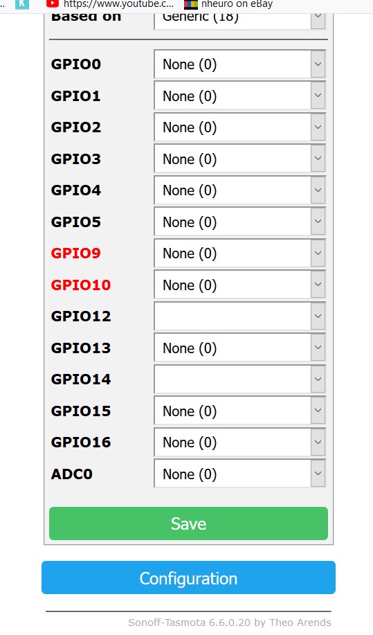
I updated to 6.6.0.20 and did {"NAME":"LSC RGBCW LED","GPIO":[0,0,0,0,0,0,0,0,181,0,180,0,0],"FLAG":0,"BASE":18}
But dont see it to controll my e14 light its not seeing 181 and 180 they are empty
 maffemuis
on 21 Oct 2019
maffemuis
on 21 Oct 2019
Usually, if the pin names do not appear in the dropdown then the binary does not include support for it.
 andrethomas
on 22 Oct 2019
andrethomas
on 22 Oct 2019
See releasenotes which binary supports your sm2135.
arendst
on 22 Oct 2019
Solved at Discord. He used Sonoff-Basic. After upgrading to sonoff.bin it works as expected....
Jason2866
on 22 Oct 2019
So I've done some measurements and comparisons with the original LSC firmware and the Tasmota build. I've measured temperature and light output for each channel in the same condition for each bulb.
Output (in lux):
LSC: WW 4350, CW 5050, R 72, G 154, B 225
TAS: WW 3050, CW 3480, R 64, G 125, B 205
Temp (in Celcius) after 10 minutes:
LSC: WW 51, CW 56, R 34, G 32, B 31
TAS: WW 42, CW 48, R 34, G 32, B 31
Temp (in Celcius) after 20 minutes:
LSC: WW 60, CW 62, R 34, G 33, B 33
TAS: WW 49, CW 52, R 34, G 33, B 33
Temp (in Celcius) after 30 minutes:
LSC: WW 63, CW 56, R 34, G 33, B 33
TAS: WW 51, CW 53, R 34, G 34, B 33
The Warm White and Cold White have less heat but also less light output so I'm guessing the mA can be upped a bit.
Regarding the RGB values they are the same on both firmwares, however looking at the temperature I guess the mA can be upped as well, making the bulb perform 'better' with Tasmota compared to the original firmware.
redahb
on 3 Nov 2019
@redahb thx.
To increase current you might want to change line 54 in file xlgt_04_sm2135.ino from
const uint8_t SM2135_CURRENT = (SM2135_20MA << 4) | SM2135_10MA;
in
const uint8_t SM2135_CURRENT = (SM2135_25MA << 4) | SM2135_15MA;
and redo your measurements.
Pls report back if the results compare better.
arendst
on 3 Nov 2019
New results:
I upped the CW/WW tot 15mA and this brought the WW to 4300lx and CW to 5000lx, which is pretty much spot on with the original firmware. So my guess is 15mA would be the optimal 'same-as-factory' setting. Personally I like the lesser temperature with 10mA (10 degrees is quite a lot) because in my house GU10 bulbs are rarely lighting a room by themselves (it's always a cluster of 2 or more) so I don't need the full brightness. I'll leave the decision up to you ;)
RGB is a different story. As stated before, the RGB values from Tasmota vs LSC firmware are a tad bit dimmer but not by much. If you didn't have a lux meter you wouldn't notice. Having said that, I've bumped up the mA in increments up to 40 mA but didn't know if I should push further. What I'm noticing is:
- With 30mA, R bumps from 64 to 98lx (overshooting the LSC 72lx), G from 125lx to 130 lx (LSC 154lx), B from 205lx to 218lx (LSC 225lx).
- With 40mA, R goes up to 122lx, G to 135lx, B to 224lx. Temperature is around 36 degrees Celcius after 30 minutes so temperature-wise there's no worries yet.
Conclusion: Basically with 40mA Red overshoots, Green isn't performing like the original firmware yet, and Blue is sort of on par. I would have expected a much bigger difference in brightness but to the naked eye I can barely see difference between 20mA and 40mA. With CW/WW, I _can_ see a difference by only a 5mA increase.
As it stands, both with LSC firmware and Tasmota firmware the RGB colors are pretty weak compared to other bulbs. That's disappointing, but as I'm not knowledgeable about the SM2135 chip at all, I have no idea if we should and can push the RGB channels further. Temperature probably isn't the only limit I guess? And do we want this bulb to behave 'better' on Tasmota or do we want to copy the factory specifications?
Again, decision up to you ;)
redahb
on 4 Nov 2019
Thx again!
I'll up the CW/WW to 15mA and leave the RGB as they are saving power while no real difference in lux.
arendst
on 4 Nov 2019
Hello,
i have here an E27 model with Tuya TYWE3L Wifi module. It is an RGBW lamp with 11W. (See Google: SKU-2752) According to Tuya there is the ESP8266 installed. As with the GU10 and E14 variant of LSP here is an SM2135E installed, but the GPIO assignment does not match. Has anyone found out the right assignment?
Greeting,
Alex
 alex200580
on 23 Nov 2019
alex200580
on 23 Nov 2019
I have 2 LSC GU10 spots and flashed them with Tasmota. I have a connection, can upgrade the firmware but can't turn turn the lights on or off.
This is my setting.
{"NAME":"LSC RGBCW LED","GPIO":[0,0,0,0,0,0,0,0,181,0,180,0,0],"FLAG":0,"BASE":18}
One light worked but stopped working after a power cycle. I can still reach them with wifi (Tasmota)
 Knol010
on 27 Dec 2019
Knol010
on 27 Dec 2019
Same here only the e14 rgb bulb
 wolfpins
on 29 Dec 2019
wolfpins
on 29 Dec 2019
Did you include support for the sm2135? I may not be compiled in and therefore wont work.
TimelessNL
on 29 Dec 2019
Thanks , i saw the sm2135 but have not figured out how to flash it to the bulb or where to put it
wolfpins
on 29 Dec 2019
What you mean? The .bin has support for the sm2135 chip or it doesn't. There is no separate file you have to flash.
TimelessNL
on 29 Dec 2019
@wolfpins
Please, address this to the Tasmota Support Chat. The chat is a better and more dynamic channel for helping you. Github issues are meant for Tasmota Software Bug Reporting.
Please check the Contributing Guideline and Policy and the Support Guide.
Thanks.
Support Information
See Wiki for more information.
See FAQ for common questions/answers and links if none of your question is in the list
See Chat for more user experience.
See Community for forum.
See Code of Conduct
ascillato
on 29 Dec 2019
Related issues
 grizewald
·
3Comments
grizewald
·
3Comments
 Vujagig
·
3Comments
Vujagig
·
3Comments
 Ndrinta
·
3Comments
Ndrinta
·
3Comments
 ximonline
·
3Comments
ximonline
·
3Comments
 belidzs
·
3Comments
belidzs
·
3Comments
Most helpful comment
Released support for SM2135 using the template below: