Tasmota: Support for Shelly 2 and Shelly 1 ?
Hi Theo,
can tasmota get support for Shelly 2?
https://shelly.cloud/shelly2/
Shelly 2 is very small wifi device with 2 relays, power meter and should also use ESP8266.
In most cases, it fits in a German flush mount box (60 mm Ø and 40 mm depth), including the previous switch and is therefore invisible.
I think there are many users who would like to use shelly 2 with tasmota.
 h-tro
h-tro
All 112 comments
Interesting device (not such low priced as Sonoff devices)
but might be not as simple as it looks because
Has an integrated precise power meter
 curzon01
on 21 May 2018
curzon01
on 21 May 2018
i think the power meter would not work anymore.
i have read about other devices which power meter and it did not work anymore after flashing tasmota.
 reloxx13
on 24 May 2018
reloxx13
on 24 May 2018
I have opened a shelly2 (https://shelly.cloud/shelly2)
It contains an ESP8266EX with 2 MB flash memory (WINBOND 25Q16BVFIG)
and a power monitoring IC MCP39F501 (https://www.microchip.com/wwwproducts/en/MCP39F501)
h-tro
on 20 Jun 2018
Hi,
There are 5 pins on the backside of the board. I've traced them out, there are all you need. From top to bottom (3 pin group is top)
RX
TX
VCC
(Groupe of 2)
Gpio 0
GND
 senfkorn
on 30 Jun 2018
senfkorn
on 30 Jun 2018
Next step,
The two current shunts for the both relais outputs are coupled together to the MCP39F501. So it is not easily possible to measure each output individually.
senfkorn
on 30 Jun 2018
Hi senfkorn,
yes, I can confirm the assignment of the pins on the backside of the board.
I have the same result.
h-tro
on 30 Jun 2018
Hi, anyone successfully installed tasmota on Shelley? Even without the power meter feature?
 tmarquespt
on 5 Aug 2018
tmarquespt
on 5 Aug 2018
Hi, I bought the Shelly 1.
Link
He has none power meter feature but he ist very cheap and fits also in a German flush mount box.
Is it possible to support this?
 NCC1701G
on 7 Aug 2018
NCC1701G
on 7 Aug 2018
Hi,
Shelly 1 is new. I will order one.
I think you can flash tasmota and use the module type "Generic" over the web interface and set up the GPIO config for shelly1
(GPIO's see https://shelly.cloud/shelly1-open-source/)
h-tro
on 8 Aug 2018
Where is the need of flashing the shelly (1)? Doesn't it work without cloud connection as the sonoff do? Thanks
 cko-skverlag
on 17 Aug 2018
cko-skverlag
on 17 Aug 2018
If you do not like having your home devices in a foreign cloud system, Tasmota is a one of the best alternative firmware.
And to get it work you need to flash.
curzon01
on 19 Aug 2018
But I thought the Shelly system comes without a cloud service?
cko-skverlag
on 19 Aug 2018
https://github.com/arendst/Sonoff-Tasmota/issues/2789#issuecomment-411327105
@h-tro Did you manage to flash the Shelly-1 with Tasmota firmware already?
 JPe2
on 20 Aug 2018
JPe2
on 20 Aug 2018
No – and i don’t understand why you would want to flash it? Isn’t there a free webserver onboard? From what i have read there is no need to connect the device to a cloud. But i’m not a technician.
Christoph
cko-skverlag
on 20 Aug 2018
Here is nice video, showing tasmota on shelly1 with ready to flash binary. https://www.youtube.com/watch?v=J20hxfUTP9I
 kuzba
on 22 Aug 2018
kuzba
on 22 Aug 2018
I have succefully flashed tasmota on the shelly1 with the .bin from link that kuzba posted.
The wifi manager mode didn't started (or at least I couldn't use it) so I had to manualy set it up with serial commands using Termite.
That .bin file already has options for the shelly1 and shelly2 so I believe the guy from TheHookUp had them both working. I'm going to flash shelly2 and let you know.
tmarquespt
on 23 Aug 2018
Are you able to run shelly again from mains (eg 230V)? I somehow destroyed the device (shelly1), it runs only from 3.3V pin header. But I probably swapped L and N wire, not sure if this can cause the trouble. So I am without toy now.
kuzba
on 23 Aug 2018
@tmarquespt let us know how to solder wires to flush shelly 2
 benzino77
on 23 Aug 2018
benzino77
on 23 Aug 2018
@benzino77 senfkorn already exaplined the pinout on the 5th post of this page. I'm still thinking on how to do it as I would avoid soldering such small pins. I'll probably make a connector with some needles and flash it without soldering.
@kuzba Mine is working. Changing L with N should make no difference as this is AC I have mine with a plug to the wall socket so I have no ideia which is the L or the N. Why do you say it's not working? It has no light. Try to connect with Termite (Mains OFF, gpio out) and send an AP command in order to see if it responds. Beaware that the connection scheme is different from the sonoff as the current does not go trough the relay by default and you have to inject it (as explained in the picture of the shelly manual included in the box)
tmarquespt
on 23 Aug 2018
@tmarquespt when running from mains, device gets really hot and does not connect to AP. When running from 3.3V thru pin header, connects to AP and responds to commands. I guess power supply is KO. PCB schematics will help.
kuzba
on 23 Aug 2018
@kuzba That is strange indeed. I can feel some temperature on mine but nothing out of the ordinary. It just might be an issue with the unit, you should try to return it and get a new one.
FYI: Theo just made Tasmota compatible with Shelly "Only INPUT available in v6.1.1.9 as Button1n option. See changelog."
tmarquespt
on 23 Aug 2018
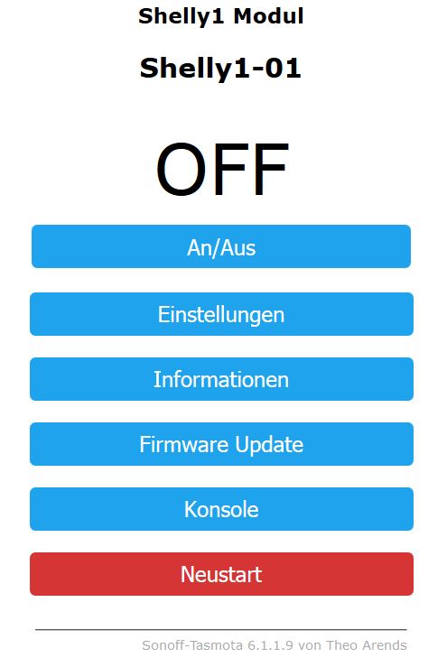
In the video GPIO05 is selected as Switch1.
I prefer to use Button1 as it will allow using the webpage for toggling the relay.
  { "Shelly1",         // Shelly 1 (ESP8266 - 2MB)
     GPIO_SWT1,        // GPIO00 Switch
     GPIO_USER,        // GPIO01 Serial RXD and Optional sensor
     0,
     GPIO_USER,        // GPIO03 Serial TXD and Optional sensor
     GPIO_REL1,        // GPIO04 Relay (0 = Off, 1 = On)
     GPIO_KEY1_NP,     // GPIO05 Button
     0, 0, 0, 0, 0, 0, // Flash connection
     0, 0, 0, 0, 0, 0
  }
Can anyone confirm that the above config works as expected?
 arendst
on 23 Aug 2018
arendst
on 23 Aug 2018
Compiling error 6.1.1.9
h-tro
on 23 Aug 2018
...senfkorn already exaplined the pinout on the 5th post of this page...
That's true, but one or two pictures will be just great.
benzino77
on 23 Aug 2018
Here is the Webpage where the video comes from:
http://www.thesmarthomehookup.com/the-shelly-1-smart-relay-is-it-better-than-the-sonoff-basic/
 papaloewe
on 23 Aug 2018
papaloewe
on 23 Aug 2018
In this video he says the pull-up resistors have to be disabled, can that be done as part of the module preset? https://youtu.be/J20hxfUTP9I?t=416
 ethan4
on 23 Aug 2018
ethan4
on 23 Aug 2018
@benzino77 Sure :)
@senfkorn / @h-tro Can you confirm that this is correct?

tmarquespt
on 23 Aug 2018
@ethan4 It should be working on the last version of Tasmota v6.1.1.9. If you want to make that change it has to be on the source before compile. You cannot change that after flashing. You might just flash the .bin file that is on the description of that video. Then you just select Shelly1 Module from configuration.
tmarquespt
on 23 Aug 2018
@tmarquespt I'll try that, but that means there will have to be a different .bin for this device always right? Can the ability to change that be added and then made customisable in the UI?
Not everyone using Tasmota is competent to compile it themselves.
ethan4
on 23 Aug 2018
@arendst
I have the following configuration for my shelly1 (own bin-file):
{ "Shelly1", // Shelly1 (ESP8266 - 2MB)
GPIO_KEY1, // GPIO00 Button
GPIO_USER, // GPIO01 Serial TXD and Optional sensor
0,
GPIO_USER, // GPIO03 Serial RXD and Optional sensor
GPIO_REL1, // GPIO04 Relay 1 (0 = Off, 1 = On)
GPIO_SWT1_NP, // GPIO05 External switch input 1
0, 0, 0, 0, 0, 0, // Flash connection
0, 0, 0, 0, 0, 0
},
After a first test it seems to work.
I will test it further and report in the next few days.
h-tro
on 24 Aug 2018
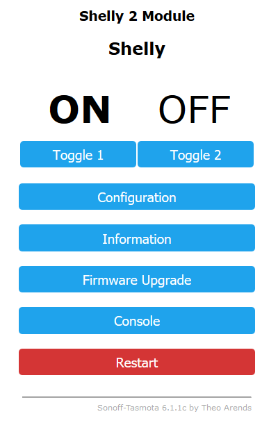
It seems to work on shelly2 (the .bin from the video)
I was able to flash and have the relays clicking.
tmarquespt
on 24 Aug 2018
@tmarquespt using your shelly2 can you confirm that when you perform toggle 1 that indeed output NO1 is switched?
I ask as I suspect the relays are connected reversed based on (ancient) information from Olimex (https://github.com/OLIMEX/olimex-iot-firmware-esp8266) and my interpretation.
So I would expect that when you perform Toggle 1 output NO2 would be switched when using the pre-compiled binary from thehookup.
arendst
on 24 Aug 2018
arendst
on 24 Aug 2018
tmarquespt
on 24 Aug 2018
h-tro
on 24 Aug 2018
 salopette
on 24 Aug 2018
kuzba
on 24 Aug 2018
ethan4
on 24 Aug 2018
h-tro
on 25 Aug 2018
salopette
on 26 Aug 2018
h-tro
on 26 Aug 2018
salopette
on 26 Aug 2018
salopette
on 24 Aug 2018
kuzba
on 24 Aug 2018
ethan4
on 24 Aug 2018
h-tro
on 25 Aug 2018
salopette
on 26 Aug 2018
h-tro
on 26 Aug 2018
salopette
on 26 Aug 2018
 eazuka
on 26 Aug 2018
h-tro
on 27 Aug 2018
eazuka
on 26 Aug 2018
h-tro
on 27 Aug 2018
 thehookup
on 28 Aug 2018
arendst
on 28 Aug 2018
h-tro
on 28 Aug 2018
arendst
on 28 Aug 2018
thehookup
on 28 Aug 2018
arendst
on 28 Aug 2018
h-tro
on 28 Aug 2018
arendst
on 28 Aug 2018
 kiwijunglist
on 29 Aug 2018
thehookup
on 30 Aug 2018
h-tro
on 30 Aug 2018
thehookup
on 30 Aug 2018
h-tro
on 30 Aug 2018
ethan4
on 2 Sep 2018
kiwijunglist
on 29 Aug 2018
thehookup
on 30 Aug 2018
h-tro
on 30 Aug 2018
thehookup
on 30 Aug 2018
h-tro
on 30 Aug 2018
ethan4
on 2 Sep 2018
 aetjansen
on 2 Sep 2018
arendst
on 2 Sep 2018
h-tro
on 2 Sep 2018
arendst
on 2 Sep 2018
thehookup
on 2 Sep 2018
eazuka
on 2 Sep 2018
h-tro
on 2 Sep 2018
aetjansen
on 2 Sep 2018
arendst
on 2 Sep 2018
h-tro
on 2 Sep 2018
arendst
on 2 Sep 2018
thehookup
on 2 Sep 2018
eazuka
on 2 Sep 2018
h-tro
on 2 Sep 2018
 digiblur
on 3 Sep 2018
arendst
on 3 Sep 2018
kiwijunglist
on 3 Sep 2018
digiblur
on 3 Sep 2018
arendst
on 3 Sep 2018
kiwijunglist
on 3 Sep 2018
 codedmind
on 3 Sep 2018
digiblur
on 3 Sep 2018
h-tro
on 3 Sep 2018
thehookup
on 3 Sep 2018
thehookup
on 3 Sep 2018
arendst
on 3 Sep 2018
digiblur
on 3 Sep 2018
h-tro
on 3 Sep 2018
digiblur
on 3 Sep 2018
codedmind
on 3 Sep 2018
digiblur
on 3 Sep 2018
h-tro
on 3 Sep 2018
thehookup
on 3 Sep 2018
thehookup
on 3 Sep 2018
arendst
on 3 Sep 2018
digiblur
on 3 Sep 2018
h-tro
on 3 Sep 2018
digiblur
on 3 Sep 2018
 kenci
on 3 Sep 2018
kenci
on 3 Sep 2018
 CrocKlok
on 4 Sep 2018
CrocKlok
on 4 Sep 2018
 akpuggy
on 4 Sep 2018
akpuggy
on 4 Sep 2018
 Argo8
on 4 Sep 2018
digiblur
on 4 Sep 2018
Argo8
on 4 Sep 2018
digiblur
on 4 Sep 2018
 thxthx0
on 5 Sep 2018
digiblur
on 5 Sep 2018
thxthx0
on 5 Sep 2018
digiblur
on 5 Sep 2018
 ascillato
on 5 Sep 2018
digiblur
on 5 Sep 2018
CrocKlok
on 8 Sep 2018
ascillato
on 5 Sep 2018
digiblur
on 5 Sep 2018
CrocKlok
on 8 Sep 2018
 dezral
on 9 Sep 2018
dezral
on 9 Sep 2018
 AlltercoRobotics
on 10 Sep 2018
kenci
on 10 Sep 2018
ascillato
on 10 Sep 2018
eazuka
on 10 Sep 2018
ascillato
on 10 Sep 2018
AlltercoRobotics
on 10 Sep 2018
kenci
on 10 Sep 2018
ascillato
on 10 Sep 2018
eazuka
on 10 Sep 2018
ascillato
on 10 Sep 2018
 valerie16901
on 10 Sep 2018
papaloewe
on 12 Sep 2018
valerie16901
on 10 Sep 2018
papaloewe
on 12 Sep 2018
 TD-er
on 14 Sep 2018
arendst
on 16 Sep 2018
eazuka
on 17 Sep 2018
arendst
on 17 Sep 2018
TD-er
on 14 Sep 2018
arendst
on 16 Sep 2018
eazuka
on 17 Sep 2018
arendst
on 17 Sep 2018
 thecode
on 17 Sep 2018
arendst
on 17 Sep 2018
thecode
on 17 Sep 2018
arendst
on 17 Sep 2018
 meingraham
on 17 Sep 2018
arendst
on 17 Sep 2018
meingraham
on 17 Sep 2018
digiblur
on 17 Sep 2018
arendst
on 21 Sep 2018
meingraham
on 17 Sep 2018
arendst
on 17 Sep 2018
meingraham
on 17 Sep 2018
digiblur
on 17 Sep 2018
arendst
on 21 Sep 2018
 ricreis394
on 24 Sep 2018
ascillato
on 24 Sep 2018
arendst
on 25 Sep 2018
ricreis394
on 25 Sep 2018
arendst
on 25 Sep 2018
h-tro
on 25 Sep 2018
kiwijunglist
on 27 Sep 2018
ricreis394
on 24 Sep 2018
ascillato
on 24 Sep 2018
arendst
on 25 Sep 2018
ricreis394
on 25 Sep 2018
arendst
on 25 Sep 2018
h-tro
on 25 Sep 2018
kiwijunglist
on 27 Sep 2018
 oremic
on 16 Nov 2018
oremic
on 16 Nov 2018
 ascillato2
on 16 Nov 2018
oremic
on 16 Nov 2018
ascillato2
on 16 Nov 2018
oremic
on 16 Nov 2018
Related issues
 he-so
·
3Comments
he-so
·
3Comments
 Joeyhza
·
3Comments
Joeyhza
·
3Comments
 jensuffhaus
·
3Comments
jensuffhaus
·
3Comments
 abzman
·
3Comments
abzman
·
3Comments
 kckepz
·
3Comments
kckepz
·
3Comments
Most helpful comment