Hi arendt,
Great Project and many thank for your work! I love it and it's work perfect.
I know that is not project related but maybe you can help me.
I search a W-iFi dimmer for 230V/~400W for pulps. Sonoff is veyr cool but there is no dimmer :-(
Maybe you have a tip for me?
Regards,
Marc
 macpit
All 636 comments
I have not been able to find a dimmer that uses esp-8266 yet.
k
 davidelang
on 22 May 2017
davidelang
on 22 May 2017
I'm currently working on a renovation and also required 240Vac dimmers. Im running trials using a push button dimmer "SAL Push Button Dimmer 350W Master Switch SDD350TCM" which has a remote switch option SDD350TCS. The remote/slave push button is just 2off, 10K resistors in series and a tactile switch. This I have replaced with a sonoff and 2 off 10K resistors. I can turn the light on off and dim. I'm currently look at way to set dim level using a sonoff POW to measure power consumption or Current but it's a bit flaky at the moment. Work is still on going.
Jaosn
 nosaj66au
on 23 May 2017
nosaj66au
on 23 May 2017
I'm also looking for the same thing. The ability to dim 230v GU10 LED bulbs. (They are dimmable type)
 Blue407
on 3 Jul 2017
Blue407
on 3 Jul 2017
+1 I'm hopeful sonoff releases one soon
 jbarneson
on 3 Jul 2017
jbarneson
on 3 Jul 2017
Wishing for something like this:
http://www.apogeekits.com/advanced-electronic-kits/dc-light-dimmer-k8064.htm
Together with pwm out of a tasmota software in a sonoff package with CE and terminals for a wall switch, or even better, built into a sonoff touch panel.
Could we all tip sonoff/itead about it? Maybe they will make it if the interest is there?
 Amli2011
on 9 Sep 2017
Amli2011
on 9 Sep 2017
Has anyone thought about replacing the regular relay by a solid state relay? I think one of these fostek SSR should be fine with running smaller resistive loads in pwm. Could the esp8266 run pwm on the output steering the relay?
 klaernie
on 29 Sep 2017
klaernie
on 29 Sep 2017
Only in German, but google can translate
https://ex-store.de/2-Kanal-RS232-Dimmer-Modul-V4-fuer-Unterputzmontage-230V-3A
they have also the relay version (currently sold out)
https://ex-store.de/ESP8266-WiFi-Relay-V31
 hesich
on 1 Oct 2017
hesich
on 1 Oct 2017
Is there still no dimmer possible with tasmota and mqtt?
 Martinvdm
on 14 Jan 2018
Martinvdm
on 14 Jan 2018
do you have a module that has dimmer capabilities (instead of the relays that
almost all of them have)?
davidelang
on 14 Jan 2018
Martinvdm
on 14 Jan 2018
I was hoping that there was a commercial one available :-(
trying to do that sort of very precise timing on a system that is doing a lot of
other things (network I/O, etc) is going to be quite a problem
On Sun, 14 Jan 2018, Martinvdm wrote:
davidelang
on 15 Jan 2018
I have just ordered this one:
It will arrive in 10-15 Days.
Perhaps it is possible to modify the tasmota firmware to get it work.
This one seem interesting too:
https://de.aliexpress.com/item/AC110V-220V-WiFi-0-10V-Touch-Panel-LED-Dimmer-output-0-10v-dimming-signal-by-ios/32799514095.html?spm=a2g0s.8937420.0.0.714a4c39LINMVF
But it only comes in black and I need it in white
 jonas59075
on 15 Jan 2018
jonas59075
on 15 Jan 2018
Hi @jonas59075 that link does not work (I think its a copy of your order so only works when your logged in).
Was it this you were linking to? https://www.aliexpress.com/item/Best-Sales-Wallpad-White-Glass-LED-110-250V-EU-Phone-Wifi-Wireless-Remote-Controlled-Power-Dimmer/32562891943.html
Ben
 bensuffolk
on 15 Jan 2018
bensuffolk
on 15 Jan 2018
Oh, sorry for that. Yes ... your Link is the right one ...
Have anyone experience with that device?
jonas59075
on 15 Jan 2018
Thats pretty expensive, you have to be keen on dimming existing lamps I think rather than buying some dimmable ones like the B1.
But it will be interesting to see if its got the same esp8266 chip in. Nice to know what options are out there for when I come to do some more bits on my home.
bensuffolk
on 15 Jan 2018
This looks promising:
http://www.instructables.com/id/ARMTRONIX-WIFI-SINGLE-Dimmer-Board-V02/
Martinvdm
on 15 Jan 2018
Hi Guys, I think your barking up the wrong tree. If we are serious about HA we should be moving to LED, as its low power and just makes good sense. If we say YES, LED is the way to go then, everyone knows 240/110 VAC LEDs (driver and LED) are a bitch to work with and have mixed results, usually poor due to flicker etc. If we go back to electronics 101 a LED is a DC device and the best way to dim it is PWM of a suitable DC supply voltage 12/24/36 volts and the current is very low < 1-2 amps.
I recently approached Itead to provide a quotation to manufacture a T1 wall switch replacing the relay/s with Mosfet/s and a different power supply to drive the LEDs. The price was 7K USD for the proto types 1-2-3 gang and just a but to rich for an individual, but for a group ????
For the power supply we have 2 choices, power it with 240-95VAC and configure the output voltage for driving LEDs or just supply the switch with the DC voltage your LED requires. I have hacked a 3 gang T1 already by removing 3 component and install a 24vdc to 5vdc supply. Which works perfectly.
I have done many dimming trials with a H801 as it Mosfets switch the negative rail, I can remove the LED manufactures driver and power the LEDs directly using PWM giving perfect dimming 1 to 100%.
In short by combining these 2 products T1 and H801 you could end up with a great solution
What do you guys think?
Jason
nosaj66au
on 19 Jan 2018
A dimmer would still be useful for some applications. I’d like to wire up my salt lamp which has a manual dimmer at the moment, and the bulbs for a salt lamp cannot be LED.
 madjam002
on 19 Jan 2018
madjam002
on 19 Jan 2018
A dimmer would still be useful for some applications. I’d like to wire up my salt lamp which has a manual dimmer at the moment, and the bulbs for a salt lamp cannot be LED.
The same goes for Edison light bulbs.
This looks promising:
http://www.instructables.com/id/ARMTRONIX-WIFI-SINGLE-Dimmer-Board-V02/
I happened to order this before stumbling upon this thread. I'll let you know about it once I received it.
 jonathanschneider
on 15 Feb 2018
jonathanschneider
on 15 Feb 2018
This can be the solution for real dimmer (not led solution), I will give a shot
https://www.banggood.com/3Pcs-RobotDyn-AC-Light-Dimmer-Module-For-PWM-Control-1-Channel-3_3V5V-Logic-AC-50hz-60hz-220V-110V-p-1255783.html?rmmds=myorder&cur_warehouse=CN
 checksummaster
on 6 Apr 2018
checksummaster
on 6 Apr 2018
Agree let me know how it goes.
nosaj66au
on 8 Apr 2018
Any updates? I just ordered this one, since the seller told me there's an ESP8266 inside.
 stanvv
on 13 Apr 2018
stanvv
on 13 Apr 2018
I ordered one like Stanvv and it arrived today. This is what it looks like inside if anyone is interested.


 reeso3000
on 24 Apr 2018
reeso3000
on 24 Apr 2018
Does it work without changing the firmware?
 qingz2004
on 26 Apr 2018
qingz2004
on 26 Apr 2018
Yes it works without changing the firmware - Uses Smart Life app that is compatible with Alexa. The results are a bit mixed - it dims ok but the lights seem to flicker, I purchased dimmable leds (Gu10) to use in my kitchen and this is the result. Going to try it in my living room with B22 bulb to see if its any bettter.
reeso3000
on 30 Apr 2018
I bought the same one from Aliexpress, but a US version.
https://www.aliexpress.com/item/WiFi-Light-Dimmer-Switch-Stepless-Dimming-Touch-Panel-Dimmer-Work-with-Alexa-Google-Assistant-IFTTT-White/32857809626.html
It did not response or dim to the +/- touch button on the plate, but it did (some how, but not smooth) with Smart Life app. The bulb flickers a lot once dimmed. I tried with both dimmable LED and incandescent bulb.
Even worse, after I tried a few times with phone app, the dimmer is completely dead. No response to anything. Only power cycle can fix it.
I believe the MCU STM8S103F3P6 does not work or is not properly programmed, since all the touch button signals and the cross zero interrupt signal go to the MCU, and the MCU generates the PWM.
I checked with a oscilloscope, the signals go into the MCU are perfect, but the PWM generated from the MCU is not.
ESP8266 here is to communicate with the phone, and transmit the command to the MCU through the serial port.
We might be able to bypass the MCU and use the ESP8266 to do everything.
qingz2004
on 30 Apr 2018
I have the same one as @reeso3000. Im looking into modifying :D let us know if solve the issue.
They are available on Amazon UK for a fair price.
 epicality85
on 7 May 2018
epicality85
on 7 May 2018
Mine works fine with the standard app, but I'm trying to flash Tasmota. No success so far:
Got this schema of the ESP8266 by Hysiry, which is placed in the dimmer: https://fccid.io/2AKBPESP8266/User-Manual/User-Manual-3192780
I assume the schema at page 6 (3. Pin description) is flipped, see also page 13 (7. Minimum System Requirements).
I think I got it in programming mode by connecting ground with IO0, cause the left dimmer button lights up, while it doesn't light up when only connecting the programmer.
I soldered 4 pins to the board as follows. When switching 3v3 and ground it didn't power up, so I assume that is connected correctly.

But I get the 'standard' error:
warning: espcomm_sync failed
error: espcomm_open failed
error: espcomm_upload_mem failed
error: espcomm_upload_mem failed
I also tried to switch TX and RX, but that didn't work.
Anyone who can help?
stanvv
on 11 May 2018
On my US version, there is no pin hole for Tx Rx, but anyway the serial port from ESP8266 is connected to the MCU STM8S103F3P6 which I think also drives the bus. You may have to cut the trace (at least the Rx) between ESP8266 and MCU before you can flash the ESP8266.
I haven't tried that.
You may want to backup the image from the original ESP8266 before you flash it in case you want to go back, since Tasmota does not support it yet.
qingz2004
on 11 May 2018
Anybody tried this one?
https://www.amazon.com/2018Upgraded-Wireless-Assistant-Anywhere-Installation/dp/B07CL1M664
Does it use ESP8266?
qingz2004
on 14 May 2018
Im looking to buy this dimmer , any success guys !?
 ahzazou
on 19 May 2018
ahzazou
on 19 May 2018
Unfortunately not.. I tried to contact the manufacturer asking where the pins (TX/RX/GND/3V3) are placed, but I don't think they understood what I meant. Anyone who can help?
stanvv
on 24 May 2018
You need to connect those as mentioned on the board , them wile booting your esp8266 you need to connect gpio0 to ground to enable flash mode
ahzazou
on 24 May 2018
Yeah I know how to flash Tasmota in general, but I don't know which holes belong to which pins. See my previous post.
stanvv
on 24 May 2018
You can use the esp8266 type you have and it has all the pins you need
ahzazou
on 25 May 2018

This is how mine looks like. It's a USA version of the dimmer.
It is basically a ESP-12F. The picture show its backside.
qingz2004
on 25 May 2018
This one can be hacked easily as tx Rx vcc GND AND gpio0 is appearant on board
ahzazou
on 26 May 2018
As I said in the previous post, the serial port is used to connect between esp-12F and the MCU. And the MCU also drives the port when you apply the power, so you have to cut the wire before you can program the esp8266.
qingz2004
on 26 May 2018
Received this one from AliExpress today.
http://www.ihome-s.com/product/278023134
Works perfect with eWeLink and the buttons. No flickery at all when dimmed. And no flickery even with my dimmable LED bulb.
I believe it has ESP8266 since it uses eWeLink, but I can not open it and see the inside. It's really hard to open it, and I don't want to break it.
qingz2004
on 29 May 2018
I picked up:
https://www.amazon.com/gp/product/B07CTNSZZ8/ref=oh_aui_detailpage_o00_s00?ie=UTF8&psc=1
Its got a TYWE3S module in it, but I haven't had any luck in getting the device to flash. I'm able to see output on the serial port. I'll post some picture later if people are interested.
 galak
on 3 Jun 2018
galak
on 3 Jun 2018
Is there any other MCU like STM8 other than the ESP8285?
qingz2004
on 3 Jun 2018
Is there any other MCU like STM8 other than the ESP8285?
There might be, there are some chips that I haven't identified yet. Why do you ask?
galak
on 3 Jun 2018
There might be, there are some chips that I haven't identified yet. Why do you ask?
@qingz2004 Looks like there is a Nuvoton 8-bit micro
galak
on 3 Jun 2018
If there is another MCU, flash ESP8285 will not get you anywhere. The other MCU is the main processor, and the ESP8285 is used for WiFi communication only.
qingz2004
on 3 Jun 2018
Here are some images for the WIFI Dimmer:


The MCU is a Nuvoton 8-bit micro (N76E003). There is also a Byd IT Capacitive Touch Key Controller (BF6911A22)
galak
on 4 Jun 2018
If there is another MCU, flash ESP8285 will not get you anywhere. The other MCU is the main processor, and the ESP8285 is used for WiFi communication only.
I tried disconnecting the MCU and that didn't help.
galak
on 4 Jun 2018

TYWE3S is basically a packed ESP8266. From the picture, I can see only TXD, RXD, RST, EN, GPIO15, GND, and VCC are connected.
Before you flash, you have to ground GPIO0 and make sure Tx and Rx are not connected to anywhere else.
Make sure you backup the original stock image, or you may lose the control to the Dimmer. I guess all the logic is inside the MCU, like Zero cross detection, PWM generation, touch button response. While EPS8266 is just get the commands from WiFi and transfer them to the MCU through the Serial port.
qingz2004
on 4 Jun 2018
TYWE3S is basically a packed ESP8266. From the picture, I can see only TXD, RXD, RST, EN, GPIO15, GND, and VCC are connected.
Before you flash, you have to ground GPIO0 and make sure Tx and Rx are not connected to anywhere else.
Make sure you backup the original stock image, or you may lose the control to the Dimmer. I guess all the logic is inside the MCU, like Zero cross detection, PWM generation, touch button response. While EPS8266 is just get the commands from WiFi and transfer them to the MCU through the Serial port.
I'm guessing the fact that some combo of Tx/Rx seem to be connected to the cap sensor might be my issue. I've disconnected the microcontroller board, but haven't tried w/o the cap sensor. I've verified that my GPIO0 to GND is working - I'm in boot/uart flash mode based on the UART output:
ets Jan 8 2013,rst cause:2, boot mode:(1,6)
vs normal boot output of:
 ets Jan  8 2013,rst cause:2, boot mode:(3,6)

load 0x40100000, len 1396, room 16
tail 4
chksum 0x89
load 0x3ffe8000, len 776, room 4
tail 4
chksum 0xe8
load 0x3ffe8308, len 540, room 4
tail 8
chksum 0xc0
csum 0xc0

2nd boot version : 1.4(b1)
  SPI Speed      : 40MHz
  SPI Mode       : QIO
  SPI Flash Size & Map: 8Mbit(512KB+512KB)
jump to run user1 @ 1000

OS SDK ver: 1.4.2(23fbe10) compiled @ Sep 22 2016 13:09:03
phy v
Guess I need to solder to the TYWE3S pins and disconnect it from the micro & cap sensor.
galak
on 4 Jun 2018
I can't see it is connected to a cap sensor if you disconnect both ribbon cables.
It's not hard to trace the wires with a multi-meter, or even better if you have a logic analyzer to check the activities on the serial port.
qingz2004
on 4 Jun 2018
After cutting the RXD trace, I was able to read and write the flash.
My board is this. ESP-12F with 4M flash.
https://www.aliexpress.com/item/WiFi-Light-Dimmer-Switch-Stepless-Dimming-Touch-Panel-Dimmer-Work-with-Alexa-Google-Assistant-IFTTT-White/32857809626.html
Now I'm waiting for Tasmota support, so I can bypass the onboard MCU, use only the ESP8266 for everything.
Can we borrow some code from here?
qingz2004
on 9 Jun 2018
Why would you want to try and run it all from the esp? Zero cross is timing intensive especially with a chip that running WiFi and doing other duties.
 mrphyslaw
on 11 Jun 2018
mrphyslaw
on 11 Jun 2018
Why would you want to try and run it all from the esp? Zero cross is timing intensive especially with a chip that running WiFi and doing other duties.
The MCU on my dimmer does not work well. Increase/Decrease buttons do not work, and the PWM does not sync with zero cross point. The bulb is flickering a lot when dimmed. The current dimmer uses smartlife app, and I need one to work with my MQTT server so I can integrate it into my home automation system.
I don't think zero cross is that timing intensive. 60Hz AC vs 80MHz system clock.
It should be doable like this, It uses one ESP8266 to control two dimmer switches.
qingz2004
on 11 Jun 2018
I have also just received one of these and was already able to backup the original firmware, here is how I connected to the device:


 chaosmaster
on 16 Jun 2018
chaosmaster
on 16 Jun 2018
I have also just received one of these and was already able to backup the original firmware, here is how I connected to the device:
That's how I backup mine. Possible to backup the MCU firmware? Since my dimer does not work well, I guess the firmware in MCU is no good. I try to update the MCU if not bypass it.
qingz2004
on 17 Jun 2018
I haven't tried backing up the MCU firmware yet. I am currently trying to get tasmota to talk to the MCU.
I could imagine it uses the same protocol mentioned here:
https://github.com/arendst/Sonoff-Tasmota/issues/595
https://github.com/enesbcs/ESPEasyPluginPlayground/blob/master/_P165_SerSwitch.ino
I assume backing up the MCU should be possible using an STLINK v2
(I have one lying around, but haven't tried yet)
chaosmaster
on 17 Jun 2018
I have made some progress, it is indeed the same protocol, although different data-format, since it is a dimmer.
The following code snippet switches the light on (to whatever brightness-level was previously set):
````
Serial.write(0x55); // header 55AA
Serial.write(0xAA);
Serial.write(0x00); // version 00

Serial.write(0x06); // command 06

Serial.write(0x00); // length
Serial.write(0x05); // length

Serial.write(0x01); // light number
Serial.write(0x01); // boolean
Serial.write(0x00); // length
Serial.write(0x01); // length
Serial.write(0x01); // status (0 or 1)

Serial.write(0x0E); // checksum:sum of all bytes in packet mod 256
Serial.flush();
````
baudrate is 9600
I also have the format for setting the brightness, but need to test first
chaosmaster
on 17 Jun 2018
Great news keep us updated i cant wait to see more updates i really appreciate your hard efforts
ahzazou
on 17 Jun 2018
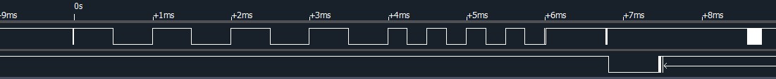
Here are the results I got with a logic analyzer. They include transmitting command and receiving feedback.
To turn on the light:
Tx:
Time [s],Value,Parity Error,Framing Error
0.0s,0x55,,
0.0010419375s,0xAA,,
0.0020838125s,0x00,,
0.00312575s,0x06,,
0.004167625s,0x00,,
0.0052095625s,0x05,,
0.0062514375s,0x01,,
0.007293375s,0x01,,
0.00833525s,0x00,,
0.0093771875s,0x01,,
0.0104190625s,0x01,,
0.011461s,0x0E,,
0.05625s,0x00,,Error
Rx:
Time [s],Value,Parity Error,Framing Error
0.0126726875s,0x55,,
0.01371s,0xAA,,
0.01474725s,0x00,,
0.0157845625s,0x07,,
0.016822s,0x00,,
0.0178594375s,0x05,,
0.01889675s,0x01,,
0.0199340625s,0x01,,
0.0209714375s,0x00,,
0.022009s,0x01,,
0.0230465s,0x01,,
0.0240840625s,0x0F,,
0.0251215625s,0x55,,
0.026159125s,0xAA,,
0.0271965s,0x00,,
0.028234s,0x07,,
0.0292715s,0x00,,
0.0303088125s,0x05,,
0.0313459375s,0x01,,
0.0323830625s,0x01,,
0.03342025s,0x00,,
0.034457375s,0x01,,
0.0354945s,0x01,,
0.0365316875s,0x0F,,
0.037569s,0x55,,
0.0386064375s,0xAA,,
0.0396438125s,0x00,,
0.0406811875s,0x07,,
0.041718625s,0x00,,
0.0427559375s,0x08,,
0.04379325s,0x02,,
0.0448305s,0x02,,
0.0458678125s,0x00,,
0.046905125s,0x04,,
0.047942375s,0x00,,
0.0489796875s,0x00,,
0.0500169375s,0x00,,
0.0510541875s,0xFF,,
0.0520914375s,0x15,,
0.05625s,0x00,,Error
To turn off light
Tx:
Time [s],Value,Parity Error,Framing Error
0.0s,0x55,,
0.0010419375s,0xAA,,
0.0020838125s,0x00,,
0.00312575s,0x06,,
0.004167625s,0x00,,
0.0052095625s,0x05,,
0.0062514375s,0x01,,
0.007293375s,0x01,,
0.00833525s,0x00,,
0.0093771875s,0x01,,
0.0104190625s,0x00,,
0.011461s,0x0D,,
0.05625s,0x00,,Error
Rx:
Time [s],Value,Parity Error,Framing Error
0.012690375s,0x55,,
0.013727375s,0xAA,,
0.0147645s,0x00,,
0.0158015625s,0x07,,
0.016838625s,0x00,,
0.017875625s,0x05,,
0.018912625s,0x01,,
0.019949625s,0x01,,
0.0209865625s,0x00,,
0.0220235625s,0x01,,
0.023060625s,0x00,,
0.0240976875s,0x0E,,
0.02513475s,0x55,,
0.0261716875s,0xAA,,
0.02720875s,0x00,,
0.0282459375s,0x07,,
0.0292829375s,0x00,,
0.030319875s,0x05,,
0.0313568125s,0x01,,
0.0323938125s,0x01,,
0.033430875s,0x00,,
0.034467875s,0x01,,
0.035504875s,0x00,,
0.036541875s,0x0E,,
0.03757875s,0x55,,
0.03861575s,0xAA,,
0.0396528125s,0x00,,
0.0406899375s,0x07,,
0.041727s,0x00,,
0.042764s,0x08,,
0.0438010625s,0x02,,
0.044838125s,0x02,,
0.0458750625s,0x00,,
0.0469119375s,0x04,,
0.047948875s,0x00,,
0.0489858125s,0x00,,
0.0500229375s,0x00,,
0.05106s,0xFF,,
0.052097125s,0x15,,
0.05625s,0x00,,Error
To increase the brightness
Tx:
Time [s],Value,Parity Error,Framing Error
0.0s,0x55,,
0.001041875s,0xAA,,
0.0020838125s,0x00,,
0.0031256875s,0x06,,
0.004167625s,0x00,,
0.0052095s,0x08,,
0.0062514375s,0x02,,
0.0072933125s,0x02,,
0.00833525s,0x00,,
0.009377125s,0x04,,
0.0104190625s,0x00,,
0.0114609375s,0x00,,
0.012502875s,0x00,,
0.01354475s,0xC0,,
0.0145866875s,0xD5,,
0.05625s,0x00,,Error
Rx:
Time [s],Value,Parity Error,Framing Error
0.0158369375s,0x55,,
0.016874125s,0xAA,,
0.0179113125s,0x00,,
0.0189484375s,0x07,,
0.019985625s,0x00,,
0.02102275s,0x08,,
0.022059875s,0x02,,
0.0230969375s,0x02,,
0.024134125s,0x00,,
0.0251713125s,0x04,,
0.0262084375s,0x00,,
0.027245625s,0x00,,
0.02828275s,0x00,,
0.0293199375s,0xC0,,
0.03035725s,0xD6,,
0.0313944375s,0x55,,
0.032431625s,0xAA,,
0.0334688125s,0x00,,
0.034506125s,0x07,,
0.0355433125s,0x00,,
0.0365804375s,0x05,,
0.0376175625s,0x01,,
0.038654625s,0x01,,
0.039691625s,0x00,,
0.040728625s,0x01,,
0.041765625s,0x01,,
0.0428025s,0x0F,,
0.0438394375s,0x55,,
0.044876375s,0xAA,,
0.0459135s,0x00,,
0.046950625s,0x07,,
0.0479878125s,0x00,,
0.0490249375s,0x08,,
0.050062125s,0x02,,
0.05109925s,0x02,,
0.052136375s,0x00,,
0.0531734375s,0x04,,
0.0542105625s,0x00,,
0.055247625s,0x00,,
0.05625s,0x00,,Error
To decrease the brightness
Tx:
Time [s],Value,Parity Error,Framing Error
0.0s,0x55,,
0.0010419375s,0xAA,,
0.0020838125s,0x00,,
0.00312575s,0x06,,
0.004167625s,0x00,,
0.0052095625s,0x08,,
0.0062514375s,0x02,,
0.007293375s,0x02,,
0.00833525s,0x00,,
0.0093771875s,0x04,,
0.0104190625s,0x00,,
0.011461s,0x00,,
0.012502875s,0x00,,
0.0135448125s,0x62,,
0.0145866875s,0x77,,
0.05625s,0x00,,Error
Rx:
Time [s],Value,Parity Error,Framing Error
0.0159045625s,0x55,,
0.0169414375s,0xAA,,
0.017978375s,0x00,,
0.0190153125s,0x07,,
0.0200523125s,0x00,,
0.02108925s,0x08,,
0.0221261875s,0x02,,
0.0231631875s,0x02,,
0.02420025s,0x00,,
0.0252371875s,0x04,,
0.02627425s,0x00,,
0.0273113125s,0x00,,
0.0283483125s,0x00,,
0.0293854375s,0x62,,
0.0304224375s,0x78,,
0.0314594375s,0x55,,
0.0324964375s,0xAA,,
0.0335334375s,0x00,,
0.0345705625s,0x07,,
0.0356076875s,0x00,,
0.0366446875s,0x05,,
0.0376816875s,0x01,,
0.0387188125s,0x01,,
0.0397558125s,0x00,,
0.04079275s,0x01,,
0.0418298125s,0x01,,
0.042866875s,0x0F,,
0.043903875s,0x55,,
0.044940875s,0xAA,,
0.045977875s,0x00,,
0.0470146875s,0x07,,
0.0480515625s,0x00,,
0.0490884375s,0x08,,
0.050125375s,0x02,,
0.0511625s,0x02,,
0.0521995s,0x00,,
0.053236625s,0x04,,
0.05427375s,0x00,,
0.0553108125s,0x00,,Error
Actually, the MCU keep sending the light status periodically. That's why we can not read or update the FW of the esp8266 without cutting the Rx trace from the PCB.
qingz2004
on 17 Jun 2018
That seems right.
I am currently able to power the light on and off.
But setting the brightness fails somehow.
From my understanding you can send the MCU an absolute brightness-level.
But that doesn't seem to work.
In your increase-command the value is 0xC0
In your decrease-command it is 0x62
Max is 0xFF and min is 0x00
Could you test if it always sends the same values when increasing or decreasing?
Edit:
Maybe it's possible to keep the MCU in a reset-state and thus flash without cutting RX?
(i.E by pulling the MCUs reset pin to some specific level)
chaosmaster
on 17 Jun 2018
check my previous post for a zero crossing + triac... it still need a esp32
but it more cheap than build the circuit yourself
On Mon, Jun 11, 2018, 9:21 AM qingz2004, notifications@github.com wrote:
Why would you want to try and run it all from the esp? Zero cross is
timing intensive especially with a chip that running WiFi and doing other
duties.The MCU on my dimmer does not work well. Increase/Decrease buttons do not
work, and the PWM does not sync with zero cross point. The bulb is
flickering a lot when dimmed. The current dimmer uses smartlife app, and I
need one to work with my MQTT server so I can integrate it into my home
automation system.I don't think zero cross is that timing intensive. 60Hz AC vs 80MHz system
clock.
It should be doable like this
http://www.instructables.com/id/Multichannel-Wireless-Light-Dimmer/—
You are receiving this because you commented.
Reply to this email directly, view it on GitHub
https://github.com/arendst/Sonoff-Tasmota/issues/469#issuecomment-396241009,
or mute the thread
https://github.com/notifications/unsubscribe-auth/AAdJwfpdvCl6uts0M9vS-y-VEzrC0J3Zks5t7m7xgaJpZM4Nhrog
.
checksummaster
on 17 Jun 2018
Could you test if it always sends the same values when increasing or decreasing?
Just tested. Every time it sends different values when increase or decrease. So you are right. It just sends the absolute brightness (PWM) value to the MCU.
Maybe it's possible to keep the MCU in a reset-state and thus flash without cutting RX?
It all depends on how strong the MCU pulls up or down the line.
It the MCU pulls down more strong than your programmer, you will not be able to pull it up.
qingz2004
on 17 Jun 2018
My MCU does not work well. Modifying the ESP8266 FW will not help.
The MCU does respond to ESP8266 commands sent from serial port, but it does not respond to the button touches (respond to on/off button, but not +/- buttons). And when the bulb dims, it flickers a lot. The PWM generated by MCU is not synced to zero crossing. I probed the PWM with an oscilloscope, half of the pulses are wrong.
I wish I can program the MCU with a good FW or totally bypass the MCU.
qingz2004
on 17 Jun 2018
It all depends on how strong the MCU pulls up or down the line.
It the MCU pulls down more strong than your programmer, you will not be able to pull it up.
I was thinking along the lines of just connecting the MCUs reset to gnd/vcc and keep it there while programming so it just doesn't boot up. Just like how it can be done with the esp as well.
I wish I can program the MCU with a good FW or totally bypass the MCU.
Using an STLINK v2 that should be possible, although i also saw some kind of update method in the serial protocol
That would also mean writing a firmware for it.
Do you think the hardware used for dimming is fine and its just an MCU issue or could it also be a hardware issue?
chaosmaster
on 17 Jun 2018
I was thinking along the lines of just connecting the MCUs reset to gnd/vcc and keep it there while programming so it just doesn't boot up. Just like how it can be done with the esp as well.
As long as it is not tri-stated during reset, it has some strength to pull up or down.
Do you think the hardware used for dimming is fine and its just an MCU issue or could it also be a hardware issue?
I believe it is mcu software issue. I probed the touch button signal and cross zero detection signals which go into mcu are all good. And I bought a few of those dimmers, all have the same problem.
Mines are US version.
qingz2004
on 18 Jun 2018
Since I just had to reflash the device, I tried without disconnecting RX and connecting MCUs reset pin to GND while flashing.
This worked well, the NRST pin of the MCU is even exposed on the header (I mislabeled it before):

I also got setting brightness working ( I did a mod 255 instead of a mod 266 for the checksum)
chaosmaster
on 18 Jun 2018
@stanvv @reeso3000 @qingz2004 @epicality85:
I have tasmota mostly working, I have attached the firmware, if you care to test.
After some code cleanup I will publish the modified sources as well.
The Firmware starts in WPS_CONFIG _AP_ mode initially, to enable AP-mode _reset WIFI:_
- Switch dimmer off using the center button
- Press down button for +/-20 seconds (until the green LED starts blinking)
What's working:
- Switching light on and off
- Setting brightness
- Sync on/off state when set through the dimmer
- Switch to AP-Mode for configuration using reset-procedure
- Control green LED
- _Sync brightness when set through dimmer_
What isn't working (yet):
Syncing brightness-level when set through the dimmer
For flashing without cutting any traces, check my previous post
chaosmaster
on 18 Jun 2018
Good job!
What isn't working (yet):
- Syncing brightness-level when set through the dimmer
For the feedback from the MCU, check my previous post.
I believe each frames starts with 0x55AA. So my feedback message contains 3 frames. Not sure which one is the real one.
Since the +/- buttons do not work with my dimmer, I can not capture the message when you set the brightness through the dimmer.
qingz2004
on 18 Jun 2018
I am getting the feedback from the MCU.
I just haven't figured out how to set it inside tasmota without causing it to again set the dimmer etc.
Since the +/- buttons do not work with my dimmer, I can not capture the message when you set the brightness through the dimmer.
I wonder why your buttons don't work.
They work fine for me. also dimming seems fine as well (I couldn't see any flicker)
What kind of lighting are you using?
I am currently testing with an IKEA 6.3W dimmable 230V LED
chaosmaster
on 18 Jun 2018
I think the MCU sends the brightness and on/off status to esp8266 periodically. You just need to decode it and set it on GUI. Do not need to send any command to MCU.
My dimmer is USA version (check my previous post with picture), the code in MCU is wrong. I'm using incandescent bulb for test. Tried a dimmable LED, same result.
qingz2004
on 18 Jun 2018
I think the MCU sends the brightness status to esp8266 periodically. You just need to decode it and set it on GUI. Do not need to send any command to MCU.
Decoding already works, set "weblog 4" in webconsole to see debug-output.
but setting the state inside tasmota without causing it to send it to the MCU because it thinks it received through mqtt or web etc, I'm not sure how yet. (I am not deeply familiar with tasmota-source, I just started digging into it)
My dimmer is USA version (check my previous post with picture), the code in MCU is wrong. I'm using incandescent bulb for test. Tried a dimmable LED, same result.
There is an update-procedure in the serial-protocol have you tried doing a firmware-update using the original esp-firmware?
Maybe that will push a corrected version to the MCU.
I assumed the code running on the MCU in the US and the EU-Version is the same, maybe it's not?!
I'll see if I get around to dumping the firmware of the MCU using STLINK v2.
I assume the unlabeled pin in my previous image is the SWIM of the MCU so the header should have all pins needed for connecting STLINK v2.
On your US-Board the unpopulated header on the bottom right is probably the same pinout.
chaosmaster
on 18 Jun 2018
What do you mean "an update-procedure in the serial-protocol"? I see there is FW update from the SmartLife app, I have not tried that yet. Will try it tonight after work.
I ordered STLINK a month ago, have not received it yet. I have all the hole labelled (V S G N) on my PCB.
Here is the other side of my board. The touch sensor wired to a unknown chip CR302, and then the debounced signals go to the MCU. Can you check which pins on your MCU receive the touch sensor signals? Try to see if they are the same on mine. If they are the same, I should be able to us the FW from EU version.
I also attached picture of the PWM generated from MCU. Ch1 is PWM, ch2 is cross zero. You will see they come in pairs. If one pulse from each pair is good, the other one is not good. That's why my bulb flickering.


qingz2004
on 18 Jun 2018
What do you mean "an update-procedure in the serial-protocol"?
The protocol used for the communication between MCU and ESP also includes commands for updating the MCU firmware. So if there is an update for the original firmware, it might also include an update for the MCU.
I ordered STLINK a month ago, have not received it yet.
That sucks, might as well order another one :P, they are available from Amazon prime for around 7 bucks.
The touch sensor wired to a unknown chip CR302, and then the debounced signals go to the MCU. Can you check which pins on your MCU receive the touch sensor signals?
The touch-buttons go to pins 2,3,5 of the CR302 (which is labeled differently on the EU-Version: CR302 B751T004CG4, maybe just a serial-number?).
I was able to find the following connections between the MCU and the CR302
MCU CR302
5    15
6    13
7    10
9    11
10   12
I see the header on yours is even labeled:
V(CC) S(WIM) G(ND) N(RST)
chaosmaster
on 18 Jun 2018
I ordered the STLink from AliEpress and shipped from China. It normally arrives in 60 days.
Thanks for the connections info between MCU and CR302. I will check mine when I get home after work.
Hope they are the same.
qingz2004
on 18 Jun 2018
Here is the connections on my PCB.
MCU CR302
5 15
6 14
7 10
9 11
10 13
Besides 7 and 9 on MCU are ground and power, only pin 5 are correct which I think it's for the middle button (on/off) which works for me. Pin 6 and 10 are one pin off on CR302.
Please make sure the connections you put are right! I'm going to cut and re-connect my PCB after you confirmed.
Even I correct the connections, make the +/- buttons work on my dimmer, I still get the bulb flickering when dimmed.
From the picture I captured with an oscilloscope, the first pulse in the pair is synced with cross zero, but I think every second pulse is calculated from first pulse, not from cross zero point. And the calculation is based on 50Hz AC, not 60Hz which is used in North American.
If that's the case, your MCU code won't work for my dimmer. Mine may already have the same MCU code.
Just checked with SmartLife app. I already have the latest firmware.

qingz2004
on 19 Jun 2018
I have made some progress with syncing brightness, although it's still not perfect.
The logic is still a bit messy since syncing the brightness is tricky.
Please test:
sonoff-tuya.zip
Please make sure the connections you put are right! I'm going to cut and re-connect my PCB after you confirmed.
I will check again to make sure.
It sure sounds like they planned different firmwares for the US-MCU and the EU-MCU, but somehow the EU-Version ended up on your device.
EDIT:
Actually your measurements are correct, I must have shifted by one.
EDIT2:
Mostly working now
chaosmaster
on 19 Jun 2018
Actually you're measurements are correct, I must have shifted by one.
So if I have the same MCU FW as yours, the buttons should work at least.
qingz2004
on 19 Jun 2018
Yes I don't see why they wouldn't if it's not a hardware-issue.
I'm not sure what MCU FW I have, but I assume it's the same.
You could try with my tasmota-port If you get anything from the MCU when pressing the buttons, but that's unlikely.
chaosmaster
on 19 Jun 2018
I don't think so, since my logic analyzer did not catch any activity from the serial port when I press a button.
qingz2004
on 19 Jun 2018
Maybe it's something about the CR302, mine clearly has a different marking:

The one mentioned here is the same as yours, so it's not a serial number.
chaosmaster
on 19 Jun 2018
As I said in previous post, I checked with a oscilloscope, the signals go into the MCU from CR302 are perfect when I touch the buttons. I didn't record the pin number at that time.
qingz2004
on 19 Jun 2018
I've got it mostly working now, still needs a bit of testing and cleanup though:
sonoff-tuya.zip
Code is available here:
https://github.com/chaosmaster/Sonoff-Tasmota/tree/tuya-dimmer
I also changed the default mode to AP since WPS is useless for me.
Please test and report
EDIT:
updated firmware
chaosmaster
on 19 Jun 2018
@qingz2004
I have dumped the MCU firmware using https://github.com/vdudouyt/stm8flash and STLINK v2
It seems stm8flash also supports flashing STM8 using an ESP with this Firmware:
https://github.com/rumpeltux/esp-stlink
I'm unsure If the firmware contains any device-specific information.
It is 5378 Bytes (after stripping the trailing 0-bytes)
The MD5SUM of the stripped file is 47f6b2cd4af222bcbad5d0662a760ddf
The MD5SUM of the unstripped file is ba03ae2d5cdb47014f96b17601706490
chaosmaster
on 20 Jun 2018
@chaosmaster
Great!
Looks like I can use my NoceMCU to flash the MCU before I get the STLink.
Where can I get your MCU dump?
Thanks!
qingz2004
on 20 Jun 2018
Looks like there isn't any device-specific information in there,
the only sensible strings in there are 1.0.0 and bSXSSFArVKtc4DyC,
which are the version and product_key.
All device specific information is stored inside the ESP.
Please make a backup of your MCU, I would really like to compare the two:
stm8flash -p stm8s103f3 -c espstlink -s flash -r mcu-backup.bin
Here is my stripped dump:
mcu-dump.zip
chaosmaster
on 20 Jun 2018
Thanks for the MCU dump.
I will dump mine and flash yours.
Before that, I need to install esp-open-sdk and build an esp FW. Not sure if there is any issue there.
qingz2004
on 20 Jun 2018
Compiled the new stm8flash which supports espstlink.
Built the esp firmware with esp-open-sdk.
Will flash my NodeMCU and try when I get home after work.
qingz2004
on 20 Jun 2018
Flashed NodeMCU with espstlink FW.
Stuck at "Determine FLASH area" when I tried to read MCU flash with NodeMCU.
Do I need to do anything to make the MCU in flash mode like esp8266?
qingz2004
on 21 Jun 2018
As mentioned in esp-stlink Readme, it doesn't support reset.
So you will probably have to reset the MCU manually (by connecting NRST to GND)
chaosmaster
on 21 Jun 2018
Reset, still the same.
Shall I keep it in reset?
I think I need to read how the MCU programming work, or just wait for my STLink v2. It's almost 60 days since I ordered it. Should arrive in a few days.
qingz2004
on 21 Jun 2018
- Did you use a 1K-Pullup between SWIM and VCC as mentioned in the Readme?
- Is your NodeMCU running at 80MHz?
here is some documentation on SWIM (pages 8 upwards)
I believe you just have to pull reset low while starting stm8flash, I don't think it should stay connected.
chaosmaster
on 21 Jun 2018
Yes, I have 1K pull up.
I guess the clock is defined in the ESP FW. I have no way to set or change it. I believe espstlink FW will set it at 80MHz.
qingz2004
on 21 Jun 2018
The Arduino-IDE lets me set the CPU-frequency in the board-settings, so I assume it is defined in the linker-script.
What do the LEDs look like while you're trying to run stm8flash?
AFAIR they should be off, while in SWIM-mode.
chaosmaster
on 21 Jun 2018
When I run stm8flash, nothing happened on the board. All 3 LEDs are on. So it's not in SWIM mode. How can I set it to that mode? Pulling the RSTN down make the LEDs off, release RSTN, LEDs back to on.
stm8flash still stuck at "Determine FLASH area".
qingz2004
on 21 Jun 2018
Could you upload your compiled esp-stlink?
I can try with a NodeMCU
chaosmaster
on 21 Jun 2018
"make flash" generates two files and flashes both files into NodeMCU at two locations.
If you read the Makefile, the command is as following.
$(ESPTOOL) --baud 460800 --port $(ESPPORT) write_flash $(FW_FILE_1_ADDR) $(FW_FILE_1) $(FW_FILE_2_ADDR) $(FW_FILE_2)
FW_FILE_1_ADDR is 0, and FW_FILE_2_ADDR is 0x10000.
The command from the terminal windows is like this:
"esptool.py --baud 460800 --port /dev/ttyUSB0 write_flash 0x00000 firmware/0x00000.bin 0x10000 firmware/0x10000.bin"
Here are the espstlink firmware and stm8flash with support of espstlink.
firmware.zip
stm8flash.zip
qingz2004
on 21 Jun 2018
OK, I tried with your firmware (I used my own stm8flash though)
It worked fine this way:
Connect everything up as in the readme besides NRST.
Pull NRST low and keep it there.
run
stm8flash -p stm8s103f3 -c espstlink -s flash -r mcu-backup.bin
now I get:
Determine FLASH area
Due to its file extension (or lack thereof), "mcu-backup.bin" is considered as RAW BINARY format!
Reading 8192 bytes at 0x8000... Command 0x01 failed with code: 0x01

Requested 8192 bytes but received only 0.
Failed to read MCU
Now when I disconnect NRST from GND the LEDs stay off (MCU is now in SWIM mode)
Now just run the same command again without NRST connected and I get:
Determine FLASH area
Due to its file extension (or lack thereof), "mcu-backup.bin" is considered as RAW BINARY format!
Reading 8192 bytes at 0x8000... OK
Bytes received: 8192
- Check your connections
- Try running as Admin/sudo
EDIT:
just checked, just to be sure, it also works with your stm8flash
chaosmaster
on 21 Jun 2018
I changed to a different NodeMCU with espstlink flashed, and keep the RSTN low. Sometimes I got the same error as yours, sometimes different error. But as soon as I release RSTN, all LEDs light up.
qingz2004
on 21 Jun 2018
What happens when you start stm8flash without the nodemcu connected?
Do you get different errors? (That would indicate that stm8flash is able to talk to the nodemcu at least)
I assume, there must be an issue with your SWIM connection or the 1K-pullup-resistor.
The pin on your board labeled S is connected to D2 on the nodemcu and via a 1K-pullup-resistor also to 3v3.
If the leds light up, after disconnecting NRST the MCU never receives the SWIM-sequence.
chaosmaster
on 21 Jun 2018
I flashed 2 NodeMCUs, they have different behaviors. One stuck at "Determine FLASH area", and one looks good. I got the same error as you if I keep RSTN to ground.
I did get different errors with and without MCU connected.
I metered 1K between V and S. And S is connected to D02 on my NodeMCU.
The only issue I found is the VCC was less than 3.0V. Sometimes even less than 2.8V. Not sure if this will cause problem.
qingz2004
on 21 Jun 2018
I will probe SWIM signal tomorrow. It's too late today.
qingz2004
on 21 Jun 2018
I have added support for reset to esp-stlink:
https://github.com/chaosmaster/esp-stlink
Connect NRST to D1
I have also started implementing a replacement firmware for the MCU, so far as a POC it just
toggles the LEDs when the corresponding button is pressed:
mcu-replacement.zip
I have a few more insights of the GPIO-Mapping:
LED1 PC4 (PIN 14)
LED2 PC5 (PIN 15)
LED3 PC3 (PIN 13)
BUTTON1 PA2 (PIN 6)
BUTTON2 PA3 (PIN 10)
BUTTON3 PA1 (PIN 5)
ESP_GPIO0 PD4 (PIN 1)
There is also 3 pins connected to the other PCB (I assume for the PWM and Zero-Crossing)
NC PC6 (PIN 16)
PWM PC7 (PIN 17)
ZERO_X PD2 (PIN 19)
Since you already checked with a logic analyzer, maybe you can tell which is which?
EDIT:
Updated information (thanks @qingz2004)
chaosmaster
on 21 Jun 2018
Are you sure they are pin 17, 18, 19? They are 16, 17, 19 on mine.
Pin 16 is not connected on the power PCB.
Pin 17 is PWM goes to the power PCB driving a triac through an optocoupler.
Pin 19 is zero crossing detector from the power PCB through another optocoupler.
BTW, the MCU PCB is isolated from the main (power PCB), so it's safe to probe the signals directly.
qingz2004
on 21 Jun 2018
I checked again, and again you are correct :see_no_evil:
Thanks for the info, I don't have a logic analyzer here.
chaosmaster
on 21 Jun 2018
@chaosmaster
Actually, I didn't get the same error message as yours. It's a little different, complaining something about timing.
Determine FLASH area
Warning: remote device took 1370 cycles (17 ms) (expected: 16 ms)
Reading 8192 bytes at 0x8000... Command 0x01 failed with code: 0x1cRequested 8192 bytes but received only 0.
Failed to read MCU
Did you try my stm8flash?
May I tried yours?
qingz2004
on 22 Jun 2018
That is weird, I haven't seen this error before. Maybe it is a undervoltage issue after all?
I have tried your stm8flash, it worked for me.
Anyways here is mine:
stm8flash.zip
Also here is my patched esp-stlink with reset support:
esp-stlink-with-reset.zip
chaosmaster
on 22 Jun 2018
Disconnected the VCC wire and connected the dimmer to AC power, and now the voltage is 3.3v.
I can now get into SWIM mode. Either use your esp-stlink or use the original with RSTN trick.
But I still get the error message in SWIM mode but without the warning this time.
Determine FLASH area
Reading 8192 bytes at 0x8000... Command 0x01 failed with code: 0x1cRequested 8192 bytes but received only 0.
Failed to read MCUPossible my flash in MCU is bad or protected?
qingz2004
on 22 Jun 2018
Do you also get the error when you run it multiple times after you are already in swim mode?
(Best to have NRST disconnected, once in SWIM-mode to make sure it doesn't reset.)
Possible my flash in MCU is bad or protected?
Try
stm8flash -c espstlink -p stm8s103f3 -s opt -r options.opt
should give you the options if it manages to read, the first byte is the ROP-Byte, it should be 0x00;
stm8flash -c espstlink -p stm8s103f3 -u
should unlock the mcu.
You can also try to flash a single byte-file with a zero-byte to the opt area to reset the ROP byte only
dd if=/dev/zero of=00.bin bs=1 count=1
stm8flash -c espstlink -p stm8s103f3 -s opt -w 00.bin
Allways try to run the commands multiple times in a row.
chaosmaster
on 22 Jun 2018
I am getting the same error when I run the read data command multiple times after it's already in SWIM mode.
I also get errors when I try to read opt address.
$ sudo ./stm8flash -c espstlink -p stm8s103f3 -s opt -r options.opt
Determine OPT area
Reading 64 bytes at 0x4800... Command 0x01 failed with code: 0x1cRequested 256 bytes but received only 0.
Failed to read MCU
$ sudo ./stm8flash -c espstlink -p stm8s103f3 -u
Determine OPT area
Command 0x01 failed with code: 0x1c
Command 0x00 failed with code: 0x01
Unlocked device. Option bytes reset to default state.
Bytes written: 11
qingz2004
on 22 Jun 2018
the last command looks good though?
Unlocked device. Option bytes reset to default state.
Bytes written: 11
Best use the version without RESET when you are able to get to SWIM mode using the reset-trick.
I'm not sure if mine works 100%
chaosmaster
on 22 Jun 2018
Yes, I tried with the original version. The same.
qingz2004
on 22 Jun 2018
Here is the SWIM and NRST I captured when I issue the read command.
Another strange thing is I tried with 5 NodeMCUs, only one of them works (partially), the other 4 have no activity on SWIM.
With those 4 NodeMCUs, I either stuck at "Determine FLASH area", or got "Couldn't open tty: No such file or directory". They were all flashed the sameespstlink FW successfully. And they were all good if I flash Tasmota.
qingz2004
on 22 Jun 2018
The NRST seems odd, it should stay low most of the time and only go up in the end.
Compare here page 9.
I think stm8flash is hardcoded to use /dev/ttyUSB0. It is likely udev is putting your other NodeMCUs to a different device. You should check if stm8flash is talking to the correct device
EDIT:
SWIM seems to also be much more reliable, when the ESP is quiet.
PULL the ESPs RESET to LOW while running stm8flash
chaosmaster
on 22 Jun 2018
I checked, they are all assigned as /dev/ttyUSB0. I connected them one by one. They are the only USB device.
Tried keeping the ESP reset all the time, still same error message.
Guess I have to wait for my STLink v2. Hopefully I'll get it soon.
qingz2004
on 23 Jun 2018
I hope it's not an issue with your MCU, since the buttons aren't working either,
and you tried with 5 NodeMCUs. For me it was working right away.
I'm out of ideas, hopefully you'll have better luck with the stlink.
chaosmaster
on 23 Jun 2018
@qingz2004
Since I'm playing around with writing a firmware-replacement for the MCU I got myself a Logic Analyzer.
Here you can see the difference between the original (bottom) and my (top) implementation, both at 25% duty cycle.
Although since I broke my dimmable LED I can't currently test.
You can also see, that the high phase is longer than the low phase, which results in timing differences between the on-states in my implementation. I'm not sure if this causes an issue.
The original implementation seems to have a constant offset between the on-states (which results in the shift to the zero-crossing)

Hopefully you can test at 60Hz, once you have your stlink.
chaosmaster
on 24 Jun 2018
The bottom one looks good, the gaps between the pulses are the same.
I think you are reference to both edges of the zero cross. It depends on how the threshold set, the trailing edge and the leading edge may not be the same distance. And that's causes your second pulses of each pair off from the cross point. Your bulb will flicker.
As I said the cross zero detecting logic has threshold, and it is not exactly zero, there should be some offset when you generate the PWM and you may need to adjust it to make it perfect.
To test the dimmer, the old fashion incandescent bulb is the best.
EDIT:
You can either generate only one pulse with same edge (50Hz PWM should be barely good), or generate second one based on calculation of the other edge with the AC frequency you target on (100Hz PWM is even better, but only works on 50Hz AC).
The stock MCU is generating 100Hz PWM, so it works only on 50Hz AC. It will not work for me.
qingz2004
on 24 Jun 2018
I actually found an incandescent bulb for testing.
I had to change my logic since the pulse must be turned off on the edges not on.
So it now looks more like the bottom one.
I am using 100Hz currently, but the idea is to detect the frequency by measuring the time between the edges and set the timer accordingly so it works for 50/100Hz and for 60/120Hz.
The frequency could then also be made available as a sensor in tasmota.
I couldn't notice any flicker with my 25W Incandescent bulb at 25%, even though I'm turning the pulse off right at the edge.
BTW, should your MCU really be defective, the STM8S103F3 are quite cheap.
chaosmaster
on 24 Jun 2018
That's even better if the dimmer can sense the frequency and self adjust.
Even you don't see any flicker, frequently cutting off the high current will cause a lot of issues especially the load is not pure resistance. You may use the dimmer on fans. That's why cross zero detection is so important.
qingz2004
on 24 Jun 2018
frequently cutting off the high current will cause a lot of issues especially the load is not pure resistance.
Isn't it best then to switch of right at the edges?
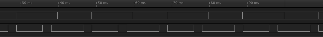
This is what it currently looks like
chaosmaster
on 24 Jun 2018
It is the best if you switch right at the cross zero point. The problem is the edge from the detector circuit is not exactly at the cross zero point. The reason is what I said "threshold". Any voltage below certain value, the circuit thinks it's zero. The "certain value" depends on the component the circuit uses.
qingz2004
on 24 Jun 2018
Now looking like this, with self-adjustment.
Working at 50Hz without flickering.
Probably still needs a bit of tweaking, but I'm hopeful it wil also work at 60Hz

chaosmaster
on 25 Jun 2018
To be able to tune the pulse, you need a oscilloscope to probe the AC sine wave. Logic analyzer will not help. Check the pictures here.
qingz2004
on 25 Jun 2018
Thanks for all the work guys, seems like you're on to something.
I've tried your altered Tasmota-firmware, which loads OK but directly after booting crashed with an Exception(0). It then goes ahead and dumps registers and the stack.
I've even uploaded a fresh firmware built from your branch through Ardiuno IDE - same.
Any pointers are very welcome.
 zeddski
on 26 Jun 2018
zeddski
on 26 Jun 2018
That is weird, are you using the same Hardware?
chaosmaster
on 26 Jun 2018
Hard to say, since there are no real labels or markings. All previously uploaded photo's are the same as mine. I'll try a different device (bought three), let's see if it's maybe hardware related.
(hard to get everything connected though)
zeddski
on 26 Jun 2018
I just tested again with this one (It is build straight from the git) and with a clean config on the device:
sonoff-tuya.zip
It is working fine for me.
Have you plugged in the dimmer or are you powering it through USB?
chaosmaster
on 26 Jun 2018
Through USB - will try mains
zeddski
on 26 Jun 2018
Good call - connectivity works. Will test with lights later and report back - thanks!!
zeddski
on 26 Jun 2018
Works like a charm. Getting the thing flashed is somewhat of a hassle with all the wiring but once flashed and connected to main power, it behaves like a regular Tasmota-enabled Sonoff device. Great work people!
zeddski
on 26 Jun 2018
Works like a charm.
Thanks for the feedback. If you encounter any issues, let me know.
Getting the thing flashed is somewhat of a hassle with all the wiring.
It would've been great, had they broken out the UART-connections.
They seem to have had the MCU planned as the core of the device (for which a debugging port is available)
chaosmaster
on 26 Jun 2018
A little update on the mcu-replacement.
I had some issues with flickering caused by UART-interrupts, but I think I have eliminated them now.
What's working:
- Detect mains-frequency and adjust PWM accordingly
- Control via Tasmota (using the same serial-protocol as the original MCU firmware)
- Control via buttons
What isn't:
- Settings aren't retained when power is lost
- Holding up/down buttons to change brightness multiple steps (currently need to be pressed once for each in/decrement)
- Trigger ESP_GPIO0 using reset procedure
Overall I still consider this alpha but most features available on the original FW are already working.
For anyone willing to test:
mcu-replacement.zip
chaosmaster
on 28 Jun 2018
@chaosmaster Great! I will test it as soon as I get the STLink v2.
qingz2004
on 28 Jun 2018
@qingz2004 that would be great.
BTW: I have noticed I suddenly had issues using esp-stlink with NodeMCU but not with stlinkv2.
After I changed the jumper wires it worked well again.
It seems stlinkv2 is much more resilient to poor connections.
Just another idea you could try.
chaosmaster
on 28 Jun 2018
@chaosmaster
What tools you used to flash esp-stlink to NodeMCU?
Did you use the Makefile to compile and flash or use other tools to just flash the FW?
qingz2004
on 29 Jun 2018
I just used make flash.
But when I tried your binary it also worked using esptool.py
chaosmaster
on 29 Jun 2018
Just a little update:
mcu-replacement.zip
- Cleanup/Refactor code (Removed dependencies from SPL to save space. (The MCU only has 8K))
- Improved button handling (Now works as expected, including reset-procedure)
- Store state to EEPROM (currently only happens, when power is toggled)
Still needs more testing and improvements.
Since most of the basic functionality works, I will soon publish the code after some more cleanup.
chaosmaster
on 30 Jun 2018
@chaosmaster
Hi. Could you share with us the mcu (stm8) source code ? The one redesigned by you.
Thank you.
 alex-sever-h
on 2 Jul 2018
alex-sever-h
on 2 Jul 2018
@alex-sever-h as mentioned in my previous post, I will after some more work.
Have you tested it? I would appreciate some feedback!
chaosmaster
on 3 Jul 2018
@chaosmaster
I just received a couple of dimmers, and they seem to be the same model as those listed on this thread. (ESP + STM8). The stlink v2 device is still on the road, but I will try flashing through ESP initially.
Hope I have some time in the evening to give it a go, and give you feedback.
I was curious about the source code of the STM8, to be able to fix some issues if they arise. And / or implement new features.
alex-sever-h
on 3 Jul 2018
@chaosmaster
Hi. I managed to test the firmware you built. Works great :+1:
However, I had a few issues around flashing actually. It seems that the board is extremely sensitive to power supply.
Using just my FTDI 3.3V rail it kept swithing on/off completely, even with stock firmware. Then I switched to an arduino 3.3V power, and I was able to flash the ESP, but kept looping on Exception 0 - Illegal instruction . Also, with improper supply, the STM8 kept toggling ON / OFF the light, with your firmware.
When I switched to a proper power supply, all works nice.
When you are ready to share, I would gladly help on the STM8 development.
alex-sever-h
on 4 Jul 2018
And a small bug.
If dimmer is >= 97 when I toggle OFF then ON (web interface or button), the light remains off (even though the mqtt says clearly that it is ON)
alex-sever-h
on 4 Jul 2018
Using just my FTDI 3.3V rail it kept swithing on/off completely, even with stock firmware.
I haven't had any issues using my FTDI for power, as long as the MCU is kept in reset.
When you are ready to share, I would gladly help on the STM8 development
Even though it's still a bit messy, i have uploaded the code here:
https://github.com/chaosmaster/tuya_mcu/tree/master/stm8_tuya
If dimmer is >= 97 when I toggle OFF then ON (web interface or button), the light remains off (even though the mqtt says clearly that it is ON)
That should be fixed now.
I have also included preliminary support for acting as a mains-frequency sensor.
I have updated my Tasmota-fork to display the frequency in debug log (Weblog 4).
It seems to always be a little below the frequency as published here for example:
https://www.netzfrequenz.info/verlauf-3-minuten
chaosmaster
on 4 Jul 2018
Hello guys im reciving my dimmer tomorrow and would love to test your configuration on my dimmer too , i hVe ftdi cable and ST Link v2 any help would ve apreciated
ahzazou
on 13 Jul 2018
@ahzazou all the information should be here in this thread. If you have any specific questions we may be able to help you better.
chaosmaster
on 14 Jul 2018
As i understand to program the dimmer there is two parts , ESP8266 and MCU part , esp will use your custom frimware based on tasmota frimware ? Is it a must to program the MCU as well , if so where i can locate the swim gnd vcc and NRST on board in order to program the MCU ?
As i understand to program esp we need to connect NRST to gnd Right ?
Sorry im bit confused and sorry if im asking many questions .
Thanks in advance
ahzazou
on 18 Jul 2018
As i understand to program the dimmer there is two parts , ESP8266 and MCU part , esp will use your custom frimware based on tasmota frimware ?
Correct
Is it a must to program the MCU as well , if so where i can locate the swim gnd vcc and NRST on board in order to program the MCU ?
Flashing the MCU is optional if you are running it at 50Hz.
Check the following Image:
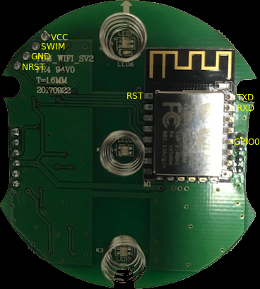
As i understand to program esp we need to connect NRST to gnd Right ?
Correct
chaosmaster
on 18 Jul 2018
Hello ,
I want to thank you for your great effort , dimmer works perfectly through mqtt and really stable and no issues at all , for me very stable , i just flashed esp8266 and works perfectly .
I have one question as i made my own dimmer before using arduino nano , esp8266 and dimmer module from robotdyn , my dimmer was working fine and works fine with really low levels of dimming . Can we configure the mcu stm8 to accept more lower level of dimming as the lowest dimming value here with this module is not really dimmed .
I really thank you again for your effort
ahzazou
on 23 Jul 2018
@ahzazou
I'm not quite sure, when I set the dimmer to 1% the MCU actually sets it to 2/255.
With my lights they start flickering at such low levels.
If that doesn't work for you, you can still try the replacement-firmware for the MCU.
chaosmaster
on 24 Jul 2018
I notices with modified mcu light flickers some times in 70% not in very low , can i fix the frequency like 50Hz or 60 hz manually if so can you guide me which file to modify !?
ahzazou
on 24 Jul 2018
And please if you have the original mcu hex can you share it with me , i forgot to back up the original mcu hex file
[email protected]
ahzazou
on 24 Jul 2018
I'm about to pick up the US version from aliexpress here: https://www.aliexpress.com/item/WiFi-Light-Dimmer-Switch-Stepless-Dimming-Touch-Panel-Dimmer-Work-with-Alexa-Google-Assistant-IFTTT-White/32857809626.html
The rear housing and PCB on the EU version is circular but the US version is rectangular... @qingz2004, I saw you disassembled the US version. Where are the NRST and SWIM pins? Did you end up flashing the MSU as well or just the ESP?
 hawkeye217
on 24 Jul 2018
hawkeye217
on 24 Jul 2018
I have tested the modified MCU and faced these issues . Frequency here is 60hz by the way it was working fine with original mcu firmware but my problem was it was not dimmed enough for me with this new mcu frimware its dimmed to low levels which is perfect but some issues as below . Its great effort to reach this point just small bugs and i believe it will be perfect .
Light flickers from time to time no matter low or hight brightness .
Mcu does not turn on the light if you use the dimmer slider to turn on the light . If you use the on off command it will work .
So lets say i turn light off , then i se slider to turn the light on light will never be on , but if use on or off button it will work then we can use slider in tasmota
ahzazou
on 25 Jul 2018
@hawkeye217 on the US-Version the pins are labeled:
https://github.com/arendst/Sonoff-Tasmota/issues/469#issuecomment-398124496
VSGN = V(CC) S(WIM) G(ND) N(RST)
@ahzazou interesting you say it works for you at 60Hz with the original firmware, do you have the EU-Version or the US-Version?
To bad you didn't dump the MCU-firmware.
You can find a dump here:
https://github.com/arendst/Sonoff-Tasmota/issues/469#issuecomment-398632456
about the unresponsiveness I believe that is caused by the delay for blinking the LED when dimming, I'll have to think of a better way to do that.
About the random flickering I am unsure how to best debug this.
Any help with the MCU/STM8-part is welcome.
chaosmaster
on 25 Jul 2018
@hawkeye217
The pins are clearly labelled on the PCB.
I haven't flash anything yet, only dumped the ESP8266 firmware.
Still waiting for the STLink v2 programmer.
qingz2004
on 25 Jul 2018
@chaosmaster @qingz2004 Great, didn't realize it was labeled directly on the PCB. Thanks!
I'll give your custom Tasmota a try when the order comes. Just to confirm: I'll connect NRST to GND, then connect my FTDI pins to the ESP and flash as usual? I'll use the stock MCU for now. Anything I'm missing to get this Tasmota-ized?
EDIT: went back and read the whole thread. Sorry for asking the questions you guys already answered earlier :)
hawkeye217
on 25 Jul 2018
@ahzazou
Mcu does not turn on the light if you use the dimmer slider to turn on the light . If you use the on off command it will work .
Could you check SetOption20 ?
https://github.com/arendst/Sonoff-Tasmota/wiki/Commands#setoption-overview
chaosmaster
on 25 Jul 2018
@chaosmaster
Mcu works fine with 60 hz on eu version , for setoption 20 with it disabled or enabled it is the same issue , i returned to original mcu its more stable for now , for the dimming flickering i have used this library before very stable from this source
https://github.com/circuitar/Dimmer
I used esp8266 + arduino nano + dimmer module from robot dyn . My dimmer is working amazingly but its not like this module in wall and has no buttons.
Here is a test for my dimmer
https://youtu.be/JNpwHhW9fMA
ahzazou
on 26 Jul 2018
Finally received my STLink v2 programmer after more than 3 months waiting (ordered on Apr 24). Dumped my US version of MCU image, it is exactly the same as the EU version.
I understand why the light flickers when dimmed since the AC is 60Hz instead of 50Hz, but I don't understand why the increase/decrease buttons do not work. Only on/off button works.
qingz2004
on 1 Aug 2018
@qingz2004
I have eu version but my frequency is 60 hz , with original mcu it works fine even with button , but when i upload the tuya_mcu itvstart flickering even in 70 % , and after 12 hours ot more , it will get unresponsive at certain time and you have to reset mcu to make it work again.
ahzazou
on 1 Aug 2018
@ahzazou
Have you dumped the mcu? Is it the same as chaosmaster's stock mcu image? Mine is the same.
qingz2004
on 1 Aug 2018
@qinqz2004
To be honest when i flashed my mcu , i did not take backup , i flashed it with modified firmware from chaosmaster’s tuya_Mcu , then i used his stock mcu on my stm8 chip it works as it was before when i tried it first time with stock mcu .
Yours is not working through buttons , does it work on wifi !? Are facing any flickering issues !? My electricity here 60hz , with stock mcu no flickering .
ahzazou
on 1 Aug 2018
@ahzazou I have a few ideas how to improve the firmware, but I haven't had time to do that yet.
The library you have linked to is for Arduino, since the MCU is an STM8 I won't be able to use it.
@qingz2004 Could you test my firmware yet? Do the buttons not work there either?
@alex-sever-h Have you had a chance to look at the firmware further?
chaosmaster
on 1 Aug 2018
@chaosmaster I haven't tried you firmware yet. You firmware is hex file, not the raw bin file.
Can I use the following command to flash the firmware? Or do I have to convert it to bin file first?
stm8flash -p stm8s103f3 -c stlinkv2 -s flash -w STM8S103.hex
qingz2004
on 1 Aug 2018
@qingz2004 yes, stm8flash should autodetect the correct format.
chaosmaster
on 1 Aug 2018
Will try it tonight after I get home.
Thanks!
qingz2004
on 1 Aug 2018
@chaosmaster Flashed mcu with your image file successfully, but did not work.
LED changes between blue and orange when I press the on/off button, but light did not turn on. No response to +/- buttons.
Flash back to stock, as before. Light turn on or off when I press on/off button.
Do I have to flash ESP8266 firmware to get the button work with the new mcu image?
qingz2004
on 2 Aug 2018
@qingz2004
LED changes between blue and orange when I press the on/off button, but light did not turn on.
That indicates it is switched on and off but is probably dimmed to 0.
No response to +/- buttons.
There must be some hardware issue then I suppose.
Do I have to flash ESP8266 firmware to get the button work with the new mcu image?
I really haven't tested without using tasmota, where you could also try to set the brightness.
chaosmaster
on 2 Aug 2018
Flashed Tasmota Tuya Dimmer to ESP8266. Everything looks good except the bulb did not light.
The LEDs responded to GUI and buttons.
Tried on two Dimmers, same problem.
Got one instance, the bulb lit up, and everything is good. No flicker when dimmed. After power cycle, the bulb did not light again.
Measured the PWM pin, zero.
qingz2004
on 2 Aug 2018
Everything looks good except the bulb did not light.
Hmm, if you set dimmer to 100 and power on, it doesn't light up?
The LEDs responded to GUI and buttons.
So the +/- Buttons do work now?
chaosmaster
on 2 Aug 2018
@chaosmaster
Right, even I set it to 100, it still doesn't light up.
The button does work, but the slide on GUI does not response to buttons
qingz2004
on 2 Aug 2018
@qingz2004
could you test using the webconsole in tasmota?
Weblog 4
Dimmer 100
Power on
Using loglevel 4 you should be able to see, if the dimmer is correctly set in the MCU
chaosmaster
on 2 Aug 2018
@chaosmaster Tried. Still the same.
Here is the message from the console. The bulb does not light.
18:07:57 MQT: tele/dim1/STATE = {"Time":"2018-08-02T18:07:57","Uptime":"0T00:02:41","Vcc":3.230,"POWER":"ON","Dimmer":100,"Fade":"OFF","Speed":1,"LedTable":"OFF"...
18:07:57 Received Frequency: 268135, 59671
Flash back to stock mcu image but keep the Tasmota in esp8266. The bulb can be turned on and off with button, and can be turned on/off as well as dimmed with GUI. +/- buttons do not work, and the bulb flickers when dimmed. Everything is back to the same as before.
With the stock mcu, after a few times on/off and dim, the bulb stops response to any command (neither GUI, nor buttons). Only LEDs responses. Have to power cycle the dimmer switch. This is also the same as before.
Probably with your mcu firmware, it goes directly to this state after power on.
qingz2004
on 3 Aug 2018
@qingz2004
The log messages I was expecting should look something like this (right after issuing the commands Dimmer 100 and Power on):
01:49:45 Setting MCU-Dimmer to 100
01:49:45 MQT: stat/sonoff/RESULT = {"POWER":"ON","Dimmer":100}
01:49:46 Received Dimmer Status: 100, Settings.light_dimmer 100, serial_in_byte 255
01:49:46 Received Power Status: 1, power:  1
01:49:46 Received Dimmer Status: 100, Settings.light_dimmer 100, serial_in_byte 255
I have an idea what could be going on. It might be related to the thresholds I defined for autodetecting the frequency. Since I never tested at 60Hz the lower threshold might have been to high and thus the PWM is never started.
I have attached a version with a decreased threshold for you to test
tuya_mcu_test.zip
@ahzazou are you sure, you are running at 60Hz?
Could you run the following command in tasmota webconsole:
Weblog 4
And look for a line like this (this only works with my MCU-firmware):
18:07:57 Received Frequency: 268135, 59671
The second number is the detected frequency multiplied with 1000.
In this example it would be 59.671 Hz
chaosmaster
on 3 Aug 2018
@chaosmaster You are right. This test image works perfect. Both GUI and buttons control the bulb smoothly. It can dim to fully off to 100% brightness. And no flicker at all when dimmed.
The only thing which can be improved is the feedback from +/- buttons to GUI. The slide from GUI does not reflect the brightness.
Thanks for the great job! My dimmer switches are finally working now.
qingz2004
on 3 Aug 2018
@qingz2004 That is great to hear!
I still wonder, why the buttons don't work for you in the stock-firmware.
But at least it doesn't seem to be a hardware-issue after all.
It is still not completely stable as I have noticed random flickering once in a while, as @ahzazou has also mentioned. (although I also have that with the stock firmware, mostly stable but now and then short flickering).
I am unsure how to best debug this, but since you also have a logic analyzer and oscilloscope, maybe you have ideas how to debug this. (I have some ideas for improving the code, but I'm not sure if that really is causing these "hickups")
About the slider, I believe this is just how tasmota works, once you refresh the page, the slider should be updated.
Also currently when moving the slider fast (i.e with the cursor-keys) to fade the light on and off, it will not work very smoothly. This is caused by the firmware switching the respective led red and blue with a delay in between.
What do you think is better, having a visual feedback using the leds or having smooth fading.
(It should probably be possible to have both, but I'm currently unsure how to best implement this)
chaosmaster
on 3 Aug 2018
@chaosmaster Can't think of any reason causes the buttons don't work with stock firmware. Tried on two dimmers, same.
I don't see any flicker even with a dimable LED bulb. Maybe I haven't tested it long enough. In this case, an oscilloscope won't help.
I see the slide does reflect the brightness if I refresh the page. Tasmota does not combine monitor and control into the same bar (EDIT: actually, it does, just not in real time. Need to refresh the page).
I don't think the visual feedback using the leds is important, since when we move the slide bar, we are normally away from the dimmer or do not look at the dimmer. You do not even need to implement the feed back from GUI control to the dimmer. I wish there are a display bar to show the percentage on the dimmer like this one, in that case, the feedback is useful.
qingz2004
on 3 Aug 2018
@chaosmaster now i installed the new hex file on mcu you added to test , no flickering its stable and weblog4 gives this output
Received Frequency: 266472, 60043
I think light is working fine even in low dim levels no flickering at all .
I think what you have done in the last hex files works great , i will test for longer period and report if anything happens.
ahzazou
on 3 Aug 2018
I don't think the visual feedback using the leds is important
I have attached a version with the delay between setting the LEDs removed (I haven't tested it yet).
It should allow smoother fading using the slider.
chaosmaster
on 3 Aug 2018
@chaosmaster I will test it this evening after work.
Visual feedback using the leds for GUI control is not that important, but feedback with LEDs for button touches is useful. I assume you didn't remove that feature.
qingz2004
on 3 Aug 2018
@qingz2004 No, feedback when using the buttons should still work.
Actually i didn't even remove the feedback completely when setting through tasmota.
I just removed the delay between setting red and back to blue, so it might just not be as visible.
chaosmaster
on 3 Aug 2018
@chaosmaster Just tried the new firmware. I love it. Much smoother. Yes, the feedback on LEDs is not visible, but who watch the LEDs on the switch when controlling with the GUI?
qingz2004
on 4 Aug 2018
@chaosmaster dimmer is working much better it flickers way less than before but after working for couple of days it flickers for like once or twice an hour , plus i lose controll from esp8266 after 2 days , if i use mqtt or tasmota web i can change brightness and turn on or off , but it will not controll mcu , if i use buttons , it will work and reflect change on esp8266 , is there any debug or tool i can use to help identify this problem ?
ahzazou
on 6 Aug 2018
After 12 hours, it does not flickers, but got similar problem as somewhat losing control from esp8266. The GUI response, but the bulb does not response to on/off button or slide bar. After several times of toggling from GUI, the bulb started to response, then stopped response again, and then started response.
There are a few possibilities I can guess.
- The code sent from ESP8266 is wrong, not completed or distorted, the mcu can not decode.
- mcu is sleeping or in certain state which does not get the command sent from ESP.
@chaosmaster I just noticed that if the light is off, touching the + or - button would not turn it on. If there is no that feature, can you add it in?
qingz2004
on 10 Aug 2018
@ahzazou @qingz2004
I'm not sure what causes the communication to break between esp and mcu.
Could you check if the webconsole in tasmota still works when this happens?
I suspect it has something to do with congestion on the serial interface.
About switching the light on using the +/- buttons, that is currently not implemented.
If I am going to implement it, i would rather make it optional and be able to set it through tasmota.
I'll have to look into that.
chaosmaster
on 10 Aug 2018
Yes, the webconsole still works fine. Are you sure the webconsole is using the serial interface?
It will be more convenience if the light can be turned on by touching any button when it's in off mode. More like the light can be turned on and set to a brightness level by moving the slide bar in GUI when the light is in off mode.
qingz2004
on 10 Aug 2018
Yes, the webconsole still works fine. Are you sure the webconsole is using the serial interface?
It isn't using the serial-interface, but I remember having a similar situation in the beginning, and then the webconsole also stopped working for some reason.
I'll see about turning on the light using the +/--buttons. I might make that the default and add the option to turn it off later.
chaosmaster
on 10 Aug 2018
I got intermittent of {"Command":"Unknown"} from web console. Here are the messages from the webconsole (removed state messages which contain my WiFi info). It's may not related to this issue. Nobody touched this dimmer during this period.
11:47:23 CMD:
11:47:23 MQT: stat/dim1/RESULT = {"Command":"Unknown"}
11:47:38 CMD:
11:47:38 MQT: stat/dim1/RESULT = {"Command":"Unknown"}
11:48:23 CMD:
11:48:23 MQT: stat/dim1/RESULT = {"Command":"Unknown"}
11:48:24 CMD:
11:48:24 MQT: stat/dim1/RESULT = {"Command":"Unknown"}
11:55:46 CMD:
11:55:46 MQT: stat/dim1/RESULT = {"Command":"Unknown"}
12:02:00 MQT: tele/dim1/UPTIME = {"Time":"2018-08-10T12:02:00","Uptime":"0T13:57:40"}
12:04:57 CMD:
12:04:57 MQT: stat/dim1/RESULT = {"Command":"Unknown"}
qingz2004
on 10 Aug 2018
@qingz2004 please always use Weblog 4 for debugging purpose.
That way we can see the messages exchanged between MCU and ESP.
I am not sure about the unknown commands, since tasmota should simply ignore any unknown command sent by the MCU. Is it possible these commands were received over MQTT or do you have MQTT disabled?
I might have have to reimplement the serial-protocol on the tasmota-side to properly check any commands sent by the MCU (although it does seem to work fine with the original MCU firmware).
Currently it only reads one byte at a time and uses a "state-machine" to interpret commands.
I did it that way because it doesn't need a buffer and therefore saves memory, and I thought this might make it easier to merge support into upstream tasmota.
However this isn't a proper implementation of the protocol and might be causing issues when receiving unexpected data (although it should simply ignore and keep going).
The code also might be confusing to follow, and doesn't easily allow adding new commands.
I would like to hear what @arendst thinks how to progress on this in order to have it merged into tasmota.
It might make sense to properly implement the serial-protocol separately from the dimmer-support, as there are other devices using the same protocol, as mentioned in #595 for example.
chaosmaster
on 11 Aug 2018
qingz2004
on 11 Aug 2018
ahzazou
on 11 Aug 2018
qingz2004
on 13 Aug 2018
ahzazou
on 13 Aug 2018
chaosmaster
on 13 Aug 2018
qingz2004
on 13 Aug 2018
chaosmaster
on 13 Aug 2018
qingz2004
on 13 Aug 2018
chaosmaster
on 13 Aug 2018
ahzazou
on 13 Aug 2018
qingz2004
on 13 Aug 2018
chaosmaster
on 13 Aug 2018
qingz2004
on 14 Aug 2018
chaosmaster
on 14 Aug 2018
qingz2004
on 14 Aug 2018
qingz2004
on 14 Aug 2018
qingz2004
on 14 Aug 2018
ahzazou
on 14 Aug 2018
ahzazou
on 14 Aug 2018
qingz2004
on 14 Aug 2018
ahzazou
on 14 Aug 2018
qingz2004
on 15 Aug 2018
chaosmaster
on 15 Aug 2018
qingz2004
on 15 Aug 2018
qingz2004
on 16 Aug 2018
hawkeye217
on 17 Aug 2018
qingz2004
on 17 Aug 2018
hawkeye217
on 17 Aug 2018
qingz2004
on 17 Aug 2018
hawkeye217
on 17 Aug 2018
qingz2004
on 17 Aug 2018
qingz2004
on 20 Aug 2018
ahzazou
on 20 Aug 2018
qingz2004
on 20 Aug 2018
hawkeye217
on 21 Aug 2018
qingz2004
on 21 Aug 2018
 Alokeen
on 22 Aug 2018
Alokeen
on 22 Aug 2018
 KonBirdy
on 28 Aug 2018
Alokeen
on 28 Aug 2018
qingz2004
on 29 Aug 2018
KonBirdy
on 29 Aug 2018
Alokeen
on 29 Aug 2018
qingz2004
on 12 Sep 2018
KonBirdy
on 28 Aug 2018
Alokeen
on 28 Aug 2018
qingz2004
on 29 Aug 2018
KonBirdy
on 29 Aug 2018
Alokeen
on 29 Aug 2018
qingz2004
on 12 Sep 2018
 ascillato
on 12 Sep 2018
ascillato
on 12 Sep 2018
 Donderda
on 12 Sep 2018
qingz2004
on 12 Sep 2018
chaosmaster
on 12 Sep 2018
ascillato
on 20 Sep 2018
Donderda
on 12 Sep 2018
qingz2004
on 12 Sep 2018
chaosmaster
on 12 Sep 2018
ascillato
on 20 Sep 2018
 enesbcs
on 20 Sep 2018
hawkeye217
on 21 Sep 2018
qingz2004
on 21 Sep 2018
qingz2004
on 21 Sep 2018
enesbcs
on 20 Sep 2018
hawkeye217
on 21 Sep 2018
qingz2004
on 21 Sep 2018
qingz2004
on 21 Sep 2018
 photinus
on 28 Sep 2018
qingz2004
on 28 Sep 2018
photinus
on 28 Sep 2018
qingz2004
on 28 Sep 2018
 coldfire84
on 4 Oct 2018
coldfire84
on 5 Oct 2018
coldfire84
on 5 Oct 2018
hawkeye217
on 5 Oct 2018
Alokeen
on 6 Oct 2018
coldfire84
on 8 Oct 2018
coldfire84
on 4 Oct 2018
coldfire84
on 5 Oct 2018
coldfire84
on 5 Oct 2018
hawkeye217
on 5 Oct 2018
Alokeen
on 6 Oct 2018
coldfire84
on 8 Oct 2018
 digiblur
on 8 Oct 2018
coldfire84
on 8 Oct 2018
digiblur
on 8 Oct 2018
coldfire84
on 8 Oct 2018
digiblur
on 9 Oct 2018
chaosmaster
on 9 Oct 2018
coldfire84
on 9 Oct 2018
chaosmaster
on 9 Oct 2018
coldfire84
on 9 Oct 2018
chaosmaster
on 9 Oct 2018
coldfire84
on 9 Oct 2018
chaosmaster
on 10 Oct 2018
coldfire84
on 10 Oct 2018
qingz2004
on 10 Oct 2018
chaosmaster
on 10 Oct 2018
qingz2004
on 10 Oct 2018
chaosmaster
on 10 Oct 2018
coldfire84
on 10 Oct 2018
hawkeye217
on 11 Oct 2018
coldfire84
on 11 Oct 2018
chaosmaster
on 12 Oct 2018
coldfire84
on 12 Oct 2018
chaosmaster
on 12 Oct 2018
hawkeye217
on 12 Oct 2018
digiblur
on 12 Oct 2018
coldfire84
on 12 Oct 2018
chaosmaster
on 12 Oct 2018
hawkeye217
on 13 Oct 2018
coldfire84
on 13 Oct 2018
chaosmaster
on 13 Oct 2018
coldfire84
on 13 Oct 2018
coldfire84
on 13 Oct 2018
hawkeye217
on 13 Oct 2018
digiblur
on 8 Oct 2018
coldfire84
on 8 Oct 2018
digiblur
on 8 Oct 2018
coldfire84
on 8 Oct 2018
digiblur
on 9 Oct 2018
chaosmaster
on 9 Oct 2018
coldfire84
on 9 Oct 2018
chaosmaster
on 9 Oct 2018
coldfire84
on 9 Oct 2018
chaosmaster
on 9 Oct 2018
coldfire84
on 9 Oct 2018
chaosmaster
on 10 Oct 2018
coldfire84
on 10 Oct 2018
qingz2004
on 10 Oct 2018
chaosmaster
on 10 Oct 2018
qingz2004
on 10 Oct 2018
chaosmaster
on 10 Oct 2018
coldfire84
on 10 Oct 2018
hawkeye217
on 11 Oct 2018
coldfire84
on 11 Oct 2018
chaosmaster
on 12 Oct 2018
coldfire84
on 12 Oct 2018
chaosmaster
on 12 Oct 2018
hawkeye217
on 12 Oct 2018
digiblur
on 12 Oct 2018
coldfire84
on 12 Oct 2018
chaosmaster
on 12 Oct 2018
hawkeye217
on 13 Oct 2018
coldfire84
on 13 Oct 2018
chaosmaster
on 13 Oct 2018
coldfire84
on 13 Oct 2018
coldfire84
on 13 Oct 2018
hawkeye217
on 13 Oct 2018
 ascillato2
on 16 Oct 2018
chaosmaster
on 16 Oct 2018
digiblur
on 16 Oct 2018
chaosmaster
on 16 Oct 2018
digiblur
on 16 Oct 2018
qingz2004
on 16 Oct 2018
coldfire84
on 16 Oct 2018
digiblur
on 16 Oct 2018
qingz2004
on 16 Oct 2018
chaosmaster
on 16 Oct 2018
chaosmaster
on 16 Oct 2018
qingz2004
on 16 Oct 2018
chaosmaster
on 16 Oct 2018
digiblur
on 16 Oct 2018
qingz2004
on 16 Oct 2018
chaosmaster
on 16 Oct 2018
qingz2004
on 16 Oct 2018
chaosmaster
on 16 Oct 2018
qingz2004
on 16 Oct 2018
chaosmaster
on 16 Oct 2018
chaosmaster
on 16 Oct 2018
qingz2004
on 16 Oct 2018
digiblur
on 16 Oct 2018
chaosmaster
on 16 Oct 2018
digiblur
on 16 Oct 2018
chaosmaster
on 16 Oct 2018
digiblur
on 17 Oct 2018
chaosmaster
on 17 Oct 2018
digiblur
on 17 Oct 2018
chaosmaster
on 17 Oct 2018
digiblur
on 17 Oct 2018
digiblur
on 17 Oct 2018
qingz2004
on 17 Oct 2018
qingz2004
on 17 Oct 2018
chaosmaster
on 17 Oct 2018
chaosmaster
on 18 Oct 2018
chaosmaster
on 18 Oct 2018
digiblur
on 18 Oct 2018
chaosmaster
on 18 Oct 2018
digiblur
on 18 Oct 2018
chaosmaster
on 18 Oct 2018
digiblur
on 18 Oct 2018
chaosmaster
on 18 Oct 2018
qingz2004
on 26 Oct 2018
ascillato2
on 16 Oct 2018
chaosmaster
on 16 Oct 2018
digiblur
on 16 Oct 2018
chaosmaster
on 16 Oct 2018
digiblur
on 16 Oct 2018
qingz2004
on 16 Oct 2018
coldfire84
on 16 Oct 2018
digiblur
on 16 Oct 2018
qingz2004
on 16 Oct 2018
chaosmaster
on 16 Oct 2018
chaosmaster
on 16 Oct 2018
qingz2004
on 16 Oct 2018
chaosmaster
on 16 Oct 2018
digiblur
on 16 Oct 2018
qingz2004
on 16 Oct 2018
chaosmaster
on 16 Oct 2018
qingz2004
on 16 Oct 2018
chaosmaster
on 16 Oct 2018
qingz2004
on 16 Oct 2018
chaosmaster
on 16 Oct 2018
chaosmaster
on 16 Oct 2018
qingz2004
on 16 Oct 2018
digiblur
on 16 Oct 2018
chaosmaster
on 16 Oct 2018
digiblur
on 16 Oct 2018
chaosmaster
on 16 Oct 2018
digiblur
on 17 Oct 2018
chaosmaster
on 17 Oct 2018
digiblur
on 17 Oct 2018
chaosmaster
on 17 Oct 2018
digiblur
on 17 Oct 2018
digiblur
on 17 Oct 2018
qingz2004
on 17 Oct 2018
qingz2004
on 17 Oct 2018
chaosmaster
on 17 Oct 2018
chaosmaster
on 18 Oct 2018
chaosmaster
on 18 Oct 2018
digiblur
on 18 Oct 2018
chaosmaster
on 18 Oct 2018
digiblur
on 18 Oct 2018
chaosmaster
on 18 Oct 2018
digiblur
on 18 Oct 2018
chaosmaster
on 18 Oct 2018
qingz2004
on 26 Oct 2018
 arendst
on 26 Oct 2018
chaosmaster
on 26 Oct 2018
qingz2004
on 26 Oct 2018
qingz2004
on 26 Oct 2018
chaosmaster
on 26 Oct 2018
qingz2004
on 26 Oct 2018
chaosmaster
on 26 Oct 2018
qingz2004
on 27 Oct 2018
chaosmaster
on 27 Oct 2018
qingz2004
on 27 Oct 2018
chaosmaster
on 27 Oct 2018
qingz2004
on 27 Oct 2018
chaosmaster
on 27 Oct 2018
qingz2004
on 27 Oct 2018
chaosmaster
on 27 Oct 2018
qingz2004
on 27 Oct 2018
chaosmaster
on 27 Oct 2018
qingz2004
on 27 Oct 2018
chaosmaster
on 27 Oct 2018
qingz2004
on 27 Oct 2018
qingz2004
on 27 Oct 2018
qingz2004
on 27 Oct 2018
chaosmaster
on 27 Oct 2018
qingz2004
on 27 Oct 2018
chaosmaster
on 27 Oct 2018
qingz2004
on 27 Oct 2018
chaosmaster
on 27 Oct 2018
qingz2004
on 27 Oct 2018
chaosmaster
on 27 Oct 2018
digiblur
on 27 Oct 2018
chaosmaster
on 27 Oct 2018
digiblur
on 27 Oct 2018
qingz2004
on 28 Oct 2018
chaosmaster
on 28 Oct 2018
chaosmaster
on 28 Oct 2018
qingz2004
on 28 Oct 2018
qingz2004
on 28 Oct 2018
chaosmaster
on 28 Oct 2018
qingz2004
on 28 Oct 2018
chaosmaster
on 29 Oct 2018
qingz2004
on 29 Oct 2018
chaosmaster
on 29 Oct 2018
qingz2004
on 29 Oct 2018
chaosmaster
on 29 Oct 2018
chaosmaster
on 29 Oct 2018
qingz2004
on 29 Oct 2018
chaosmaster
on 29 Oct 2018
qingz2004
on 29 Oct 2018
chaosmaster
on 29 Oct 2018
qingz2004
on 29 Oct 2018
chaosmaster
on 29 Oct 2018
qingz2004
on 29 Oct 2018
chaosmaster
on 29 Oct 2018
qingz2004
on 30 Oct 2018
chaosmaster
on 30 Oct 2018
qingz2004
on 30 Oct 2018
chaosmaster
on 30 Oct 2018
qingz2004
on 30 Oct 2018
qingz2004
on 31 Oct 2018
chaosmaster
on 31 Oct 2018
qingz2004
on 31 Oct 2018
qingz2004
on 31 Oct 2018
digiblur
on 31 Oct 2018
chaosmaster
on 31 Oct 2018
digiblur
on 31 Oct 2018
chaosmaster
on 1 Nov 2018
chaosmaster
on 1 Nov 2018
qingz2004
on 1 Nov 2018
chaosmaster
on 1 Nov 2018
qingz2004
on 2 Nov 2018
chaosmaster
on 2 Nov 2018
digiblur
on 2 Nov 2018
chaosmaster
on 2 Nov 2018
qingz2004
on 3 Nov 2018
chaosmaster
on 3 Nov 2018
qingz2004
on 3 Nov 2018
chaosmaster
on 3 Nov 2018
qingz2004
on 3 Nov 2018
chaosmaster
on 3 Nov 2018
qingz2004
on 3 Nov 2018
arendst
on 26 Oct 2018
chaosmaster
on 26 Oct 2018
qingz2004
on 26 Oct 2018
qingz2004
on 26 Oct 2018
chaosmaster
on 26 Oct 2018
qingz2004
on 26 Oct 2018
chaosmaster
on 26 Oct 2018
qingz2004
on 27 Oct 2018
chaosmaster
on 27 Oct 2018
qingz2004
on 27 Oct 2018
chaosmaster
on 27 Oct 2018
qingz2004
on 27 Oct 2018
chaosmaster
on 27 Oct 2018
qingz2004
on 27 Oct 2018
chaosmaster
on 27 Oct 2018
qingz2004
on 27 Oct 2018
chaosmaster
on 27 Oct 2018
qingz2004
on 27 Oct 2018
chaosmaster
on 27 Oct 2018
qingz2004
on 27 Oct 2018
qingz2004
on 27 Oct 2018
qingz2004
on 27 Oct 2018
chaosmaster
on 27 Oct 2018
qingz2004
on 27 Oct 2018
chaosmaster
on 27 Oct 2018
qingz2004
on 27 Oct 2018
chaosmaster
on 27 Oct 2018
qingz2004
on 27 Oct 2018
chaosmaster
on 27 Oct 2018
digiblur
on 27 Oct 2018
chaosmaster
on 27 Oct 2018
digiblur
on 27 Oct 2018
qingz2004
on 28 Oct 2018
chaosmaster
on 28 Oct 2018
chaosmaster
on 28 Oct 2018
qingz2004
on 28 Oct 2018
qingz2004
on 28 Oct 2018
chaosmaster
on 28 Oct 2018
qingz2004
on 28 Oct 2018
chaosmaster
on 29 Oct 2018
qingz2004
on 29 Oct 2018
chaosmaster
on 29 Oct 2018
qingz2004
on 29 Oct 2018
chaosmaster
on 29 Oct 2018
chaosmaster
on 29 Oct 2018
qingz2004
on 29 Oct 2018
chaosmaster
on 29 Oct 2018
qingz2004
on 29 Oct 2018
chaosmaster
on 29 Oct 2018
qingz2004
on 29 Oct 2018
chaosmaster
on 29 Oct 2018
qingz2004
on 29 Oct 2018
chaosmaster
on 29 Oct 2018
qingz2004
on 30 Oct 2018
chaosmaster
on 30 Oct 2018
qingz2004
on 30 Oct 2018
chaosmaster
on 30 Oct 2018
qingz2004
on 30 Oct 2018
qingz2004
on 31 Oct 2018
chaosmaster
on 31 Oct 2018
qingz2004
on 31 Oct 2018
qingz2004
on 31 Oct 2018
digiblur
on 31 Oct 2018
chaosmaster
on 31 Oct 2018
digiblur
on 31 Oct 2018
chaosmaster
on 1 Nov 2018
chaosmaster
on 1 Nov 2018
qingz2004
on 1 Nov 2018
chaosmaster
on 1 Nov 2018
qingz2004
on 2 Nov 2018
chaosmaster
on 2 Nov 2018
digiblur
on 2 Nov 2018
chaosmaster
on 2 Nov 2018
qingz2004
on 3 Nov 2018
chaosmaster
on 3 Nov 2018
qingz2004
on 3 Nov 2018
chaosmaster
on 3 Nov 2018
qingz2004
on 3 Nov 2018
chaosmaster
on 3 Nov 2018
qingz2004
on 3 Nov 2018
 badabing2005
on 4 Nov 2018
chaosmaster
on 4 Nov 2018
qingz2004
on 4 Nov 2018
chaosmaster
on 4 Nov 2018
qingz2004
on 4 Nov 2018
chaosmaster
on 4 Nov 2018
qingz2004
on 4 Nov 2018
chaosmaster
on 4 Nov 2018
qingz2004
on 4 Nov 2018
chaosmaster
on 4 Nov 2018
qingz2004
on 4 Nov 2018
chaosmaster
on 4 Nov 2018
qingz2004
on 4 Nov 2018
badabing2005
on 4 Nov 2018
qingz2004
on 4 Nov 2018
chaosmaster
on 4 Nov 2018
badabing2005
on 4 Nov 2018
qingz2004
on 4 Nov 2018
chaosmaster
on 4 Nov 2018
qingz2004
on 4 Nov 2018
qingz2004
on 4 Nov 2018
chaosmaster
on 4 Nov 2018
qingz2004
on 4 Nov 2018
qingz2004
on 4 Nov 2018
badabing2005
on 4 Nov 2018
badabing2005
on 4 Nov 2018
chaosmaster
on 5 Nov 2018
chaosmaster
on 5 Nov 2018
badabing2005
on 4 Nov 2018
chaosmaster
on 4 Nov 2018
qingz2004
on 4 Nov 2018
chaosmaster
on 4 Nov 2018
qingz2004
on 4 Nov 2018
chaosmaster
on 4 Nov 2018
qingz2004
on 4 Nov 2018
chaosmaster
on 4 Nov 2018
qingz2004
on 4 Nov 2018
chaosmaster
on 4 Nov 2018
qingz2004
on 4 Nov 2018
chaosmaster
on 4 Nov 2018
qingz2004
on 4 Nov 2018
badabing2005
on 4 Nov 2018
qingz2004
on 4 Nov 2018
chaosmaster
on 4 Nov 2018
badabing2005
on 4 Nov 2018
qingz2004
on 4 Nov 2018
chaosmaster
on 4 Nov 2018
qingz2004
on 4 Nov 2018
qingz2004
on 4 Nov 2018
chaosmaster
on 4 Nov 2018
qingz2004
on 4 Nov 2018
qingz2004
on 4 Nov 2018
badabing2005
on 4 Nov 2018
badabing2005
on 4 Nov 2018
chaosmaster
on 5 Nov 2018
chaosmaster
on 5 Nov 2018
 MangaValk
on 5 Nov 2018
digiblur
on 5 Nov 2018
chaosmaster
on 5 Nov 2018
chaosmaster
on 5 Nov 2018
digiblur
on 5 Nov 2018
chaosmaster
on 5 Nov 2018
qingz2004
on 6 Nov 2018
chaosmaster
on 6 Nov 2018
qingz2004
on 6 Nov 2018
chaosmaster
on 6 Nov 2018
badabing2005
on 6 Nov 2018
chaosmaster
on 6 Nov 2018
digiblur
on 6 Nov 2018
chaosmaster
on 6 Nov 2018
digiblur
on 6 Nov 2018
chaosmaster
on 6 Nov 2018
digiblur
on 6 Nov 2018
chaosmaster
on 6 Nov 2018
digiblur
on 6 Nov 2018
chaosmaster
on 6 Nov 2018
badabing2005
on 6 Nov 2018
digiblur
on 6 Nov 2018
chaosmaster
on 6 Nov 2018
digiblur
on 6 Nov 2018
digiblur
on 6 Nov 2018
chaosmaster
on 6 Nov 2018
digiblur
on 6 Nov 2018
chaosmaster
on 6 Nov 2018
digiblur
on 6 Nov 2018
chaosmaster
on 6 Nov 2018
digiblur
on 6 Nov 2018
chaosmaster
on 6 Nov 2018
digiblur
on 6 Nov 2018
digiblur
on 6 Nov 2018
chaosmaster
on 6 Nov 2018
digiblur
on 6 Nov 2018
chaosmaster
on 6 Nov 2018
digiblur
on 6 Nov 2018
chaosmaster
on 6 Nov 2018
digiblur
on 6 Nov 2018
chaosmaster
on 6 Nov 2018
digiblur
on 6 Nov 2018
chaosmaster
on 6 Nov 2018
digiblur
on 6 Nov 2018
chaosmaster
on 6 Nov 2018
badabing2005
on 7 Nov 2018
chaosmaster
on 7 Nov 2018
badabing2005
on 7 Nov 2018
chaosmaster
on 7 Nov 2018
badabing2005
on 7 Nov 2018
chaosmaster
on 7 Nov 2018
digiblur
on 7 Nov 2018
qingz2004
on 7 Nov 2018
chaosmaster
on 7 Nov 2018
qingz2004
on 7 Nov 2018
chaosmaster
on 7 Nov 2018
badabing2005
on 7 Nov 2018
chaosmaster
on 7 Nov 2018
qingz2004
on 8 Nov 2018
chaosmaster
on 8 Nov 2018
qingz2004
on 8 Nov 2018
badabing2005
on 9 Nov 2018
qingz2004
on 9 Nov 2018
MangaValk
on 5 Nov 2018
digiblur
on 5 Nov 2018
chaosmaster
on 5 Nov 2018
chaosmaster
on 5 Nov 2018
digiblur
on 5 Nov 2018
chaosmaster
on 5 Nov 2018
qingz2004
on 6 Nov 2018
chaosmaster
on 6 Nov 2018
qingz2004
on 6 Nov 2018
chaosmaster
on 6 Nov 2018
badabing2005
on 6 Nov 2018
chaosmaster
on 6 Nov 2018
digiblur
on 6 Nov 2018
chaosmaster
on 6 Nov 2018
digiblur
on 6 Nov 2018
chaosmaster
on 6 Nov 2018
digiblur
on 6 Nov 2018
chaosmaster
on 6 Nov 2018
digiblur
on 6 Nov 2018
chaosmaster
on 6 Nov 2018
badabing2005
on 6 Nov 2018
digiblur
on 6 Nov 2018
chaosmaster
on 6 Nov 2018
digiblur
on 6 Nov 2018
digiblur
on 6 Nov 2018
chaosmaster
on 6 Nov 2018
digiblur
on 6 Nov 2018
chaosmaster
on 6 Nov 2018
digiblur
on 6 Nov 2018
chaosmaster
on 6 Nov 2018
digiblur
on 6 Nov 2018
chaosmaster
on 6 Nov 2018
digiblur
on 6 Nov 2018
digiblur
on 6 Nov 2018
chaosmaster
on 6 Nov 2018
digiblur
on 6 Nov 2018
chaosmaster
on 6 Nov 2018
digiblur
on 6 Nov 2018
chaosmaster
on 6 Nov 2018
digiblur
on 6 Nov 2018
chaosmaster
on 6 Nov 2018
digiblur
on 6 Nov 2018
chaosmaster
on 6 Nov 2018
digiblur
on 6 Nov 2018
chaosmaster
on 6 Nov 2018
badabing2005
on 7 Nov 2018
chaosmaster
on 7 Nov 2018
badabing2005
on 7 Nov 2018
chaosmaster
on 7 Nov 2018
badabing2005
on 7 Nov 2018
chaosmaster
on 7 Nov 2018
digiblur
on 7 Nov 2018
qingz2004
on 7 Nov 2018
chaosmaster
on 7 Nov 2018
qingz2004
on 7 Nov 2018
chaosmaster
on 7 Nov 2018
badabing2005
on 7 Nov 2018
chaosmaster
on 7 Nov 2018
qingz2004
on 8 Nov 2018
chaosmaster
on 8 Nov 2018
qingz2004
on 8 Nov 2018
badabing2005
on 9 Nov 2018
qingz2004
on 9 Nov 2018
 wvdv2002
on 10 Nov 2018
badabing2005
on 11 Nov 2018
qingz2004
on 21 Nov 2018
digiblur
on 21 Nov 2018
qingz2004
on 21 Nov 2018
qingz2004
on 21 Nov 2018
digiblur
on 21 Nov 2018
chaosmaster
on 21 Nov 2018
qingz2004
on 21 Nov 2018
chaosmaster
on 21 Nov 2018
qingz2004
on 21 Nov 2018
qingz2004
on 21 Nov 2018
chaosmaster
on 21 Nov 2018
qingz2004
on 21 Nov 2018
qingz2004
on 21 Nov 2018
chaosmaster
on 21 Nov 2018
qingz2004
on 21 Nov 2018
qingz2004
on 21 Nov 2018
qingz2004
on 21 Nov 2018
chaosmaster
on 21 Nov 2018
qingz2004
on 21 Nov 2018
digiblur
on 22 Nov 2018
qingz2004
on 22 Nov 2018
chaosmaster
on 22 Nov 2018
qingz2004
on 22 Nov 2018
digiblur
on 22 Nov 2018
qingz2004
on 22 Nov 2018
digiblur
on 22 Nov 2018
wvdv2002
on 10 Nov 2018
badabing2005
on 11 Nov 2018
qingz2004
on 21 Nov 2018
digiblur
on 21 Nov 2018
qingz2004
on 21 Nov 2018
qingz2004
on 21 Nov 2018
digiblur
on 21 Nov 2018
chaosmaster
on 21 Nov 2018
qingz2004
on 21 Nov 2018
chaosmaster
on 21 Nov 2018
qingz2004
on 21 Nov 2018
qingz2004
on 21 Nov 2018
chaosmaster
on 21 Nov 2018
qingz2004
on 21 Nov 2018
qingz2004
on 21 Nov 2018
chaosmaster
on 21 Nov 2018
qingz2004
on 21 Nov 2018
qingz2004
on 21 Nov 2018
qingz2004
on 21 Nov 2018
chaosmaster
on 21 Nov 2018
qingz2004
on 21 Nov 2018
digiblur
on 22 Nov 2018
qingz2004
on 22 Nov 2018
chaosmaster
on 22 Nov 2018
qingz2004
on 22 Nov 2018
digiblur
on 22 Nov 2018
qingz2004
on 22 Nov 2018
digiblur
on 22 Nov 2018
 mohamnag
on 23 Nov 2018
digiblur
on 24 Nov 2018
chaosmaster
on 24 Nov 2018
arendst
on 24 Nov 2018
digiblur
on 24 Nov 2018
chaosmaster
on 25 Nov 2018
qingz2004
on 25 Nov 2018
qingz2004
on 25 Nov 2018
chaosmaster
on 25 Nov 2018
qingz2004
on 25 Nov 2018
chaosmaster
on 25 Nov 2018
qingz2004
on 25 Nov 2018
chaosmaster
on 25 Nov 2018
qingz2004
on 25 Nov 2018
chaosmaster
on 25 Nov 2018
qingz2004
on 25 Nov 2018
chaosmaster
on 25 Nov 2018
qingz2004
on 25 Nov 2018
chaosmaster
on 25 Nov 2018
qingz2004
on 25 Nov 2018
qingz2004
on 25 Nov 2018
chaosmaster
on 25 Nov 2018
qingz2004
on 25 Nov 2018
qingz2004
on 25 Nov 2018
chaosmaster
on 25 Nov 2018
qingz2004
on 25 Nov 2018
chaosmaster
on 25 Nov 2018
chaosmaster
on 25 Nov 2018
qingz2004
on 25 Nov 2018
qingz2004
on 25 Nov 2018
chaosmaster
on 25 Nov 2018
qingz2004
on 25 Nov 2018
chaosmaster
on 25 Nov 2018
chaosmaster
on 25 Nov 2018
qingz2004
on 26 Nov 2018
chaosmaster
on 26 Nov 2018
qingz2004
on 26 Nov 2018
chaosmaster
on 26 Nov 2018
qingz2004
on 26 Nov 2018
chaosmaster
on 26 Nov 2018
qingz2004
on 26 Nov 2018
chaosmaster
on 26 Nov 2018
mohamnag
on 23 Nov 2018
digiblur
on 24 Nov 2018
chaosmaster
on 24 Nov 2018
arendst
on 24 Nov 2018
digiblur
on 24 Nov 2018
chaosmaster
on 25 Nov 2018
qingz2004
on 25 Nov 2018
qingz2004
on 25 Nov 2018
chaosmaster
on 25 Nov 2018
qingz2004
on 25 Nov 2018
chaosmaster
on 25 Nov 2018
qingz2004
on 25 Nov 2018
chaosmaster
on 25 Nov 2018
qingz2004
on 25 Nov 2018
chaosmaster
on 25 Nov 2018
qingz2004
on 25 Nov 2018
chaosmaster
on 25 Nov 2018
qingz2004
on 25 Nov 2018
chaosmaster
on 25 Nov 2018
qingz2004
on 25 Nov 2018
qingz2004
on 25 Nov 2018
chaosmaster
on 25 Nov 2018
qingz2004
on 25 Nov 2018
qingz2004
on 25 Nov 2018
chaosmaster
on 25 Nov 2018
qingz2004
on 25 Nov 2018
chaosmaster
on 25 Nov 2018
chaosmaster
on 25 Nov 2018
qingz2004
on 25 Nov 2018
qingz2004
on 25 Nov 2018
chaosmaster
on 25 Nov 2018
qingz2004
on 25 Nov 2018
chaosmaster
on 25 Nov 2018
chaosmaster
on 25 Nov 2018
qingz2004
on 26 Nov 2018
chaosmaster
on 26 Nov 2018
qingz2004
on 26 Nov 2018
chaosmaster
on 26 Nov 2018
qingz2004
on 26 Nov 2018
chaosmaster
on 26 Nov 2018
qingz2004
on 26 Nov 2018
chaosmaster
on 26 Nov 2018
 herfel48
on 26 Nov 2018
qingz2004
on 26 Nov 2018
chaosmaster
on 26 Nov 2018
qingz2004
on 26 Nov 2018
chaosmaster
on 26 Nov 2018
qingz2004
on 26 Nov 2018
chaosmaster
on 26 Nov 2018
qingz2004
on 26 Nov 2018
chaosmaster
on 26 Nov 2018
qingz2004
on 26 Nov 2018
chaosmaster
on 26 Nov 2018
qingz2004
on 26 Nov 2018
chaosmaster
on 26 Nov 2018
qingz2004
on 26 Nov 2018
chaosmaster
on 26 Nov 2018
qingz2004
on 26 Nov 2018
chaosmaster
on 26 Nov 2018
qingz2004
on 26 Nov 2018
chaosmaster
on 26 Nov 2018
qingz2004
on 26 Nov 2018
qingz2004
on 26 Nov 2018
qingz2004
on 26 Nov 2018
chaosmaster
on 26 Nov 2018
qingz2004
on 26 Nov 2018
qingz2004
on 27 Nov 2018
chaosmaster
on 27 Nov 2018
chaosmaster
on 27 Nov 2018
qingz2004
on 27 Nov 2018
chaosmaster
on 27 Nov 2018
qingz2004
on 27 Nov 2018
chaosmaster
on 27 Nov 2018
qingz2004
on 27 Nov 2018
chaosmaster
on 27 Nov 2018
qingz2004
on 27 Nov 2018
chaosmaster
on 27 Nov 2018
qingz2004
on 27 Nov 2018
chaosmaster
on 27 Nov 2018
qingz2004
on 27 Nov 2018
chaosmaster
on 27 Nov 2018
qingz2004
on 27 Nov 2018
chaosmaster
on 27 Nov 2018
qingz2004
on 27 Nov 2018
qingz2004
on 27 Nov 2018
chaosmaster
on 28 Nov 2018
qingz2004
on 28 Nov 2018
chaosmaster
on 28 Nov 2018
chaosmaster
on 29 Nov 2018
qingz2004
on 29 Nov 2018
chaosmaster
on 6 Dec 2018
qingz2004
on 6 Dec 2018
chaosmaster
on 6 Dec 2018
qingz2004
on 6 Dec 2018
chaosmaster
on 6 Dec 2018
herfel48
on 26 Nov 2018
qingz2004
on 26 Nov 2018
chaosmaster
on 26 Nov 2018
qingz2004
on 26 Nov 2018
chaosmaster
on 26 Nov 2018
qingz2004
on 26 Nov 2018
chaosmaster
on 26 Nov 2018
qingz2004
on 26 Nov 2018
chaosmaster
on 26 Nov 2018
qingz2004
on 26 Nov 2018
chaosmaster
on 26 Nov 2018
qingz2004
on 26 Nov 2018
chaosmaster
on 26 Nov 2018
qingz2004
on 26 Nov 2018
chaosmaster
on 26 Nov 2018
qingz2004
on 26 Nov 2018
chaosmaster
on 26 Nov 2018
qingz2004
on 26 Nov 2018
chaosmaster
on 26 Nov 2018
qingz2004
on 26 Nov 2018
qingz2004
on 26 Nov 2018
qingz2004
on 26 Nov 2018
chaosmaster
on 26 Nov 2018
qingz2004
on 26 Nov 2018
qingz2004
on 27 Nov 2018
chaosmaster
on 27 Nov 2018
chaosmaster
on 27 Nov 2018
qingz2004
on 27 Nov 2018
chaosmaster
on 27 Nov 2018
qingz2004
on 27 Nov 2018
chaosmaster
on 27 Nov 2018
qingz2004
on 27 Nov 2018
chaosmaster
on 27 Nov 2018
qingz2004
on 27 Nov 2018
chaosmaster
on 27 Nov 2018
qingz2004
on 27 Nov 2018
chaosmaster
on 27 Nov 2018
qingz2004
on 27 Nov 2018
chaosmaster
on 27 Nov 2018
qingz2004
on 27 Nov 2018
chaosmaster
on 27 Nov 2018
qingz2004
on 27 Nov 2018
qingz2004
on 27 Nov 2018
chaosmaster
on 28 Nov 2018
qingz2004
on 28 Nov 2018
chaosmaster
on 28 Nov 2018
chaosmaster
on 29 Nov 2018
qingz2004
on 29 Nov 2018
chaosmaster
on 6 Dec 2018
qingz2004
on 6 Dec 2018
chaosmaster
on 6 Dec 2018
qingz2004
on 6 Dec 2018
chaosmaster
on 6 Dec 2018
 bigcookie
on 28 Mar 2019
qingz2004
on 28 Mar 2019
bigcookie
on 28 Mar 2019
bigcookie
on 28 Mar 2019
qingz2004
on 28 Mar 2019
bigcookie
on 29 Mar 2019
bigcookie
on 29 Mar 2019
digiblur
on 7 Apr 2019
bigcookie
on 28 Mar 2019
qingz2004
on 28 Mar 2019
bigcookie
on 28 Mar 2019
bigcookie
on 28 Mar 2019
qingz2004
on 28 Mar 2019
bigcookie
on 29 Mar 2019
bigcookie
on 29 Mar 2019
digiblur
on 7 Apr 2019
 blapplications
on 17 Apr 2019
blapplications
on 17 Apr 2019
 phatina
on 11 Sep 2019
phatina
on 11 Sep 2019
 adhossain
on 20 Sep 2019
adhossain
on 20 Sep 2019
 froido
on 17 Nov 2019
phatina
on 17 Nov 2019
froido
on 17 Nov 2019
phatina
on 17 Nov 2019
 kovaga
on 26 Nov 2019
kovaga
on 26 Nov 2019
 SwedishChef
on 2 Dec 2019
SwedishChef
on 2 Dec 2019
 sillician
on 14 Jan 2020
qingz2004
on 23 Oct 2020
sillician
on 14 Jan 2020
qingz2004
on 23 Oct 2020
Related issues
 ximonline
·
3Comments
ximonline
·
3Comments
 j4k3
·
3Comments
j4k3
·
3Comments
 Vujagig
·
3Comments
Vujagig
·
3Comments
 smadds
·
3Comments
smadds
·
3Comments
 Joeyhza
·
3Comments
Joeyhza
·
3Comments
Most helpful comment