Tasmota: New ESP8285 based 1Channel Inching/Locking 5V/12V Sonoff
Hi All,
I just took possession of the above new device that appears to be the new version of the old device - the pics on the Itead website has not even been updated.
This board is based on the PSF-B01 itead ESP8285 module.
I have not found any custom firmware yet that appears to work - not Tasmota, ESPEasy or Espurna seems to work.
Using Tasmota it uploads fine with success flag - but this basically puts the module in an endless switch loop with no connection to wifi as setup in config file.
Anyone have any info?
Regards,
Ed
 ed1402
All 149 comments
Hi,
I have in the same trouble.i just brought the sonoff touch few days ago,and i tried to flash the custom firmware and can't boot to the os anymore.and the serial port didn't have any output message.the wifi cannot connect and the led of the board don't blink anymore.
 xinghusp
on 16 May 2017
xinghusp
on 16 May 2017
This Device: https://www.itead.cc/smart-home/inching-self-locking-wifi-wireless-switch.html
And probably this: https://www.itead.cc/sonoff-4ch-pro.html
 sebastianlorenzen
on 16 May 2017
sebastianlorenzen
on 16 May 2017
Yes albeit not the same as in the 1 channel device photo. That indicates an ESP8266 unit. Mone is ESP8285 based.
ed1402
on 16 May 2017
The sonoff touch of mine is based on the PSF-A01 itead ESP8285 module.
xinghusp
on 16 May 2017
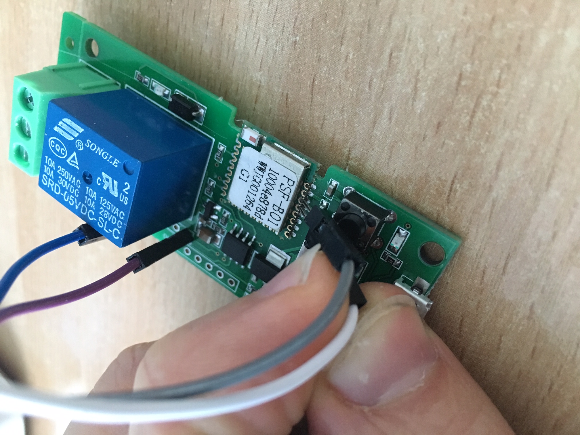
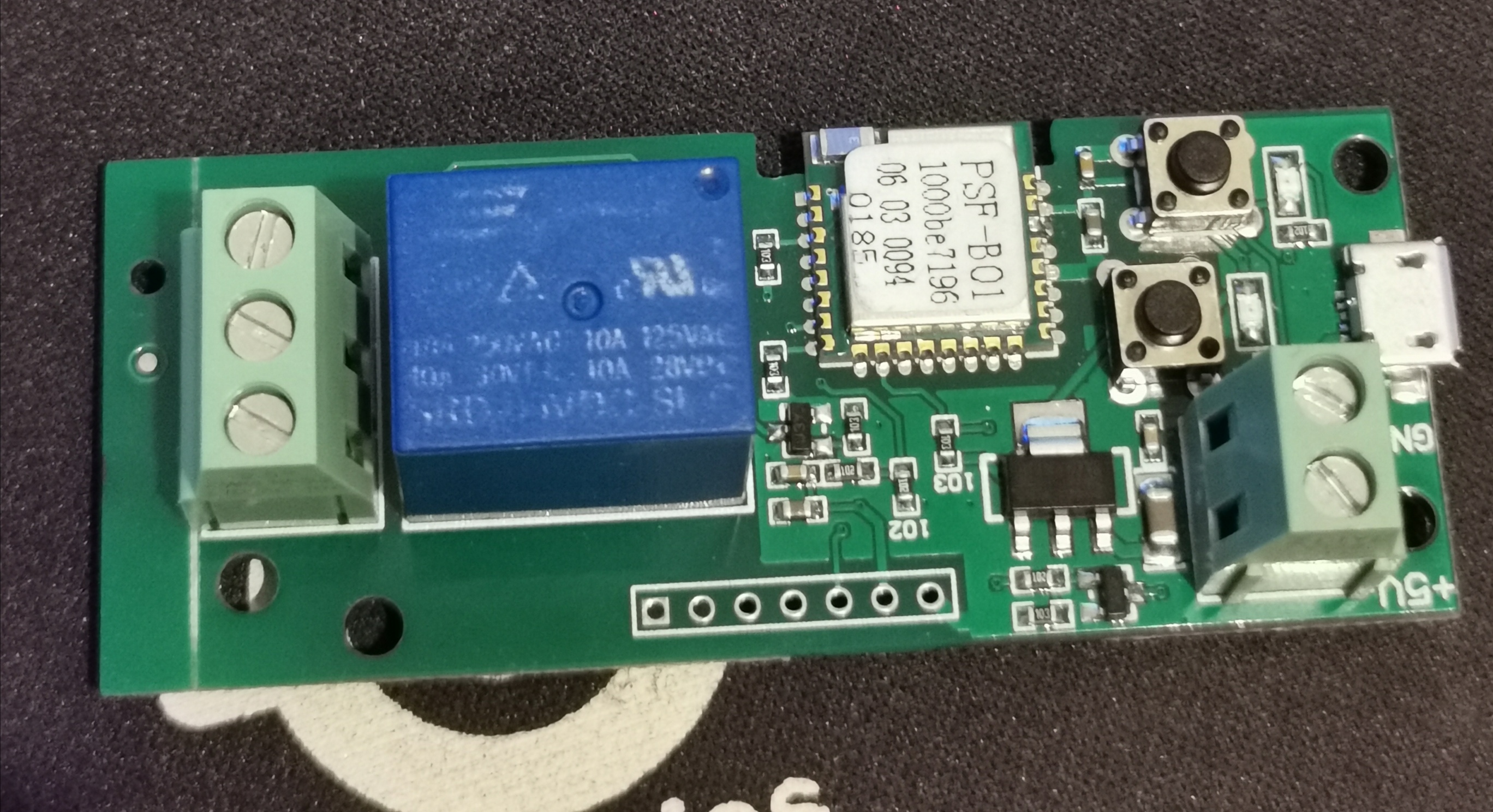
Some pics:


ed1402
on 16 May 2017
OK - so I have managed to flash the unit with Arduino IDE on latest Tasmota.
I can access the web interface after restart, but the device now shows odd behaviour.
As far as I can establish the actual locking/inching function is controlled externally to the ESP8285.
When in locking mode the device acts normally as a switch, but when in inching mode and the device is either trigger by button press or web toggle it goes into a 10 second flip flop (switching on and off repeatedly) and then hangs. After a restart the device is frozen still and I have to re-flash firmware to get it active again.
I have tried multiple device selections in the device setup (Basic, Slampher, 1 Channel and both 4 channel options.)
My assumption is that the "on" command trigger a gpio either high or low and that the external inching function sends a signal back to the ESP8285 to switch off the trigger gpio. With the new firmware this does not happen and as such the device "loops" and eventually somehow corrupts the ESP8285.
Open to any ideas?
ed1402
on 17 May 2017
tasmota has never supported the inching functionality of this board.
k
 davidelang
on 17 May 2017
davidelang
on 17 May 2017
Hello everybody!
I have received the exact same product but I can't figure out how to put it into flash mode.
Any advice?
Thanks
 paco-ita
on 20 May 2017
paco-ita
on 20 May 2017
Hi,
I am also using the same device and struggling on putting the device into flash mode (not sure about the wirings nor the procedure for setting it up into flash mode). Any advice/help would be appreciated ! Thanks
 apouzin
on 11 Jun 2017
apouzin
on 11 Jun 2017
Using Arduino (Ground to RST): on the PSFB01 you need to pull GPIO2 to Ground before Powerup and afterwards connect RX TX // TX RX using your Arduino. In my case there was no pinout on the PCB whatsoever, so I had to solder it directly on the PSFB01
 jktz90
on 19 Jun 2017
jktz90
on 19 Jun 2017
I can only assume this device is probably the latest effort from Itead to try and stop us from using custom firmware. the relay is seem to be driven by the stc15w204s.
 zizebra
on 9 Jul 2017
zizebra
on 9 Jul 2017
I was able to get this sort of working... (See attached picture) I had to remove 1 IC to stop the bouncing of the relay and bridge 2 of the empty pads. Also, need to add a pull-up resistor as indicated in the pic to make the button work after removing the IC.
I tried all tasmota configurations, and it would not work.
I was able to get it working using this firmware
https://github.com/KmanOz/Sonoff-HomeAssistant
So, at least it works now, but maybe someone smarter than I can modify the tasmota firmware (which I like better) to make it work.

 levonbragg
on 11 Jul 2017
levonbragg
on 11 Jul 2017
Brilliant stuff. Didn't think about that. Will try that and see if it helps.
zizebra
on 11 Jul 2017
The devices discussed in this issue are based on the esp8285 chip while the original device used the esp8266 chip. The main difference is the way flash is addressed and loading the default sonoff firmware on these devices will probably NOT work unless you take the following steps:
- Initially load tasmota firmware file
sonoff-touch-4ch-bnsz.binor compile your own using the DOUT flash mode. - Open the configuration webpage (or use serial commands) to select module
12 1 Channel - If things are as I expect it should now work like a standard 1 channel inching device
 arendst
on 11 Jul 2017
arendst
on 11 Jul 2017
Mine is definitely esp8285. That is the one I compiled and loaded on mine. I believe I tried the 1 channel and the behavior was not perfect. In my case, I noted that when using the inching method, it would work perfectly as expected but with one issue. I could turn on or off generally about 5 times in row. Thereafter, the next 2 or 3 attempts would not have effect.
I will test again just to verify that your suggested options works on this device.
zizebra
on 11 Jul 2017
levonbragg, do you still have the IC number for the chip you removed.
zizebra
on 11 Jul 2017
zizebra, I do not. All of mine are blank. Looks like they were rubbed off.
After digging around, it looks like a STC15F101W series 8051 micro...
levonbragg
on 11 Jul 2017
Hope itead is not trying to revive the useless ESP8266 Black board T5
zizebra
on 11 Jul 2017
arendst,
I can confirm that after adding the pullup resistor, and loading the module with the sonoff-touch-4ch firmware, and setting it to "12 1 Channel" that the board seems to be working great.
Thanks for the help!
levonbragg
on 11 Jul 2017
arendst, on my end there is no joy. I still see the behavior where some commands will have no effect. it usually takes up to 4 commands to get a response. thereafter the next 4-5 commands works before it stops responding again. below is a trace from webconsole. the highlighted power on commands did not work

zizebra
on 11 Jul 2017
@zizebra you have a MQTT server problem. This causes delays in command processing. If you fail to connect the MQTT server execute command mqttretry 60 to make more room for command processing.
arendst
on 11 Jul 2017
thank you., I didn't think that to be the problem. My sd card for my PI packed up before I received this device. I will re-install the mqtt server and test
zizebra
on 11 Jul 2017
I manage to reinstall my PI yesterday. However could not test, because my sonoff kept trying to connect to the mqtt server provided in the code instead of my custom one. It will usually connect to the correct one after a couple of hours. I hope to have a good test later on.
zizebra
on 13 Jul 2017
Finally managed to test. It is definitely working perfectly with mqtt. One minor issue which I picked up is that after loading firmware, the relay default is activated. When I choose 1ch on configuration. The relay is changed to default off. Occasionally when the sonoff restarts, the relay is activated momentarily before being Switch off. Does any one have a quick workaround for this. I would like the relay start default off throughout the reboots.
zizebra
on 13 Jul 2017
You can simply use this wiring (if you have someone to help you, you dont neet so solder).
If you use an arduino to flash: connect GROUND with RESTART on your Arduino, select ESP 8285(!) in Arduino IDE and you are good to go.

jktz90
on 7 Aug 2017
hello jktz90, please if I connect my usb to uart like this it does overheat very fast, so instead I am powering the sonoff from his own usb and connecting tx rx and Ground of module to my usb to uart but I get eeprom error, I also not sure that ESP goes into Flash mode (i assume rx pin is #5 from bottom on the image and I assume the connect to ground is the second pin from left on the bottom row of connectors. Your help greatly appreciated
 moonfarms
on 8 Aug 2017
moonfarms
on 8 Aug 2017
You probably plugged Ground/3V the wrong way around. You can definitely use your adapter to power the Sonoff.
Try switching RX with TX, the 5th pin from the button (where the red line points to) has to be connected to TX on your adapter.
Before you power up the Sonoff, you have to pull the pin out in the bottom to Ground (I don't have the official datasheet anymore) in order to force flash mode (I can't remember how exactly but the LED blinked differently to indicate the flash mode).
jktz90
on 8 Aug 2017
3v is the square pin one (blue wire on your pic) isn it? please what pin on your pic has to go to ground to enable flash
moonfarms
on 8 Aug 2017
No blue is Ground and green 3V. The pin you have to connect to Ground upon power up is in the bottom row of the ESP (where the line points to).
Make sure to select ESP 8285 in Arduino IDE
jktz90
on 8 Aug 2017
thanks again I can get it into flash mode i think (the relais keeps opening and closing) (it is also possible to do it by pressing the 2 buttons simultaneously on power up. Still no luck in flushing, but i am using platformio so maybe this is the problem. Thanks alot again jktz90 for your help, really appreciated
moonfarms
on 8 Aug 2017
Just checked it... u're in flash mode if the red led next to the relais is on permanently.
(without official firmware on it.. no idea if its different then)
jktz90
on 8 Aug 2017
can only get that red led to blink....
moonfarms
on 8 Aug 2017
jktz90 I managed to flash !!!!! THANK YOU IN CAPITAL LETTERS. Everything you wrote above is correct, led has to be solid red before flash. I dont know what i was doing wrong.....
Have a nice day
moonfarms
on 9 Aug 2017
HI Guys!
I am totally new in this Scene so please be gracious to me, i am not even a Technician.
I ordered that Item from Banggood and hoped, i will receive a ESP8266 Model, what is easy to flash by soldering some pins on the Board.
Yesterday i received the Board and was surprised by its Pinout.
So i done a Google research and luckily I found this Thread here, and that its not an ESP 8266 but an ESP 8285.
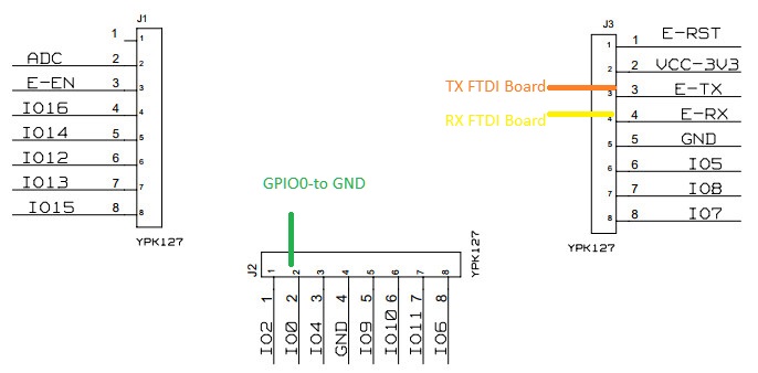
The wireing @jktz90 showed to us here confused me some, so i try to figure it out myself at looking at Datasheets.
Here is the Result:

and

What i am surprised of is, that only 3,3 Volts and GND should be at the 4 Pin Connector.
Is it really like that, that RX and TX are not supported at one of the 4 or 6 Pins Connector?
What you used to get contact to the Pins of J3 and J2 ?
Soldering cables at this Pins is nearly impossible (like i said, i am not so familiar with those Stuff)
And GPIO0 must be connected to GND to put the Board into Flashmode? It is not possible with the 2 Switches on the Board?
GND to put into flashmode can be the GND next to 3,3 Volts?
I would be happy if somebody could explain all this, hopefully jktz90 a little more detailed.
Thank you in advance
 LurchiStromberg
on 9 Aug 2017
LurchiStromberg
on 9 Aug 2017
I flashed 15 sonoff devices with zero solder, so you can do as well. Look
for "male dupont cable" that you can use between the ftdi cable and the
holes you show on your pic.
Esp 8285 does not really makes difference with 8266 as far as I know,
regarding the flash method.
Le mer. 9 août 2017 14:58, LurchiStromberg notifications@github.com a
écrit :
HI Guys!
I am totally new in this Scene so please be gracious to me, i am not even
a Technician.I ordered that Item from Banggood and hoped, i will receive a ESP8266
Model, what is easy to flash by soldering some pins on the Board.
Yesterday i received the Board and was surprised by its Pinout.
So i done a Google research and luckily I found this Thread here, and that
its not an ESP 8266 but an ESP 8285.
The wireing @jktz90 https://github.com/jktz90 showed to us here
confused me some, so i try to figure it out myself at looking at Datasheets.Here is the Result:
[image: esp 8285 anschluss ftdi pinbelegung]
https://user-images.githubusercontent.com/30866642/29122265-fc2e6cbe-7d11-11e7-89d5-3e6db378b2fc.jpgand
[image: sonoff 5v besser]
https://user-images.githubusercontent.com/30866642/29122285-0db19f24-7d12-11e7-9d21-76cd7ab91b20.jpgWhat i am surprised of is, that only 3,3 Volts and GND should be at the 4
Pin Connector.
Is it really like that, that RX and TX are not supported at one of the 4
or 6 Pins Connector?What you used to get contact to the Pins of J3 and J2 ?
Soldering cables at this Pins is nearly impossible (like i said, i am not
so familiar with those Stuff)And GPIO0 must be connected to GND to put the Board into Flashmode? It is
not possible with the 2 Switches on the Board?GND to put into flashmode can be the GND next to 3,3 Volts?
I would be happy if somebody could explain all this, hopefully jktz90 a
little more detailed.
Thank you in advance—
You are receiving this because you are subscribed to this thread.
Reply to this email directly, view it on GitHub
https://github.com/arendst/Sonoff-Tasmota/issues/453#issuecomment-321247436,
or mute the thread
https://github.com/notifications/unsubscribe-auth/AcMo5ahrmWsxIKGO7j6BMXhspLejAY2cks5sWazlgaJpZM4NbfEK
.
 PeggyFree
on 9 Aug 2017
PeggyFree
on 9 Aug 2017
I used needles to hold on rx tx pins and somebody to help to hold the board / flash firmware
moonfarms
on 9 Aug 2017
I use pogo pins, you can insert them into a female header (with effort) to keep
them aligned.
davidelang
on 9 Aug 2017
Like I said in my post, you dont need to solder. You can simply hold the male pins to the respective pin.
It made me go crazy tho, so I decided to simply solder it (took me 5 minutes). I had to flash a lot of times and holding 3 male pins is almost impossible. Find someone to help you and it should be easy.
Don't bother with the pin out on the PCB (no idea why they didnt connect it - maybe to make it harder for us to flash custom firmware), just use my connection (it will save you a lot of time).
jktz90
on 9 Aug 2017
@jktz90 The connections I posted is right ?
You also have the 1 Channel Jog inching Board?
What exact Firmware you flashed on that Board?
The Board goes in Flash Mode if I put GPIO0 to GND and connect it to the FTDI?
Sorry if i ask twice here but i like to get sure
Oh and where do i get the needed Files for ESP8285 ? I know this one http://arduino.esp8266.com/stable/package_esp8266com_index.json and i put the Link in the arduino Settings.
Is there also an URL for the 8285 or how do i get the Files Arduion needs?
LurchiStromberg
on 9 Aug 2017
Why does my connection confuse you? Its exactly what you have found in the datasheet. GPIO0 to Ground (which triggers flash mode - its enough to connect it once upon power up) and RX/TX to your FTDI adapter to send data.
After you set up your connection, go into your Arduino IDE and select ESP 8285 as your device. If you havent done it yet, go into board manager and download the ESP files.
I for myself write my own sketches. So I control the relay by UDP packets (send by my smartphone or FHEM).
But you're free to flash firmwares like ESPeasy aswell (just go to the wiki).
jktz90
on 9 Aug 2017
Sorry if i maybe annoy you, but like i said i am a bloody beginner...
And after reading hours and hours Eyes get blurry and mind freaks out ;)
So if i follow those steps like @arendst wrote before:
Initially load tasmota firmware file sonoff-touch-4ch-bnsz.bin or compile your own using the DOUT flash mode.
Open the configuration webpage (or use serial commands) to select module 12 1 Channel
If things are as I expect it should now work like a standard 1 channel inching device
so this Download:
https://github.com/arendst/Sonoff-Tasmota/releases/download/v5.2.4/sonoff-touch-4ch-bnsz.bin
Just tried it and it dont work :( Arduino give an Error Message, that it can only open its own Sketches...
It will work on my 1 CH Board?
Lasst Question (hopefully) How the Settings need to be for the ESP8285 in Arduino?
LurchiStromberg
on 9 Aug 2017
@LurchiStromberg Sorry to break in but that information has been superseded a while ago. That's what you get with old issues.
Forget about sonoff-touch..bin file. It is no longer available in the latest release.
Only use the latest release sonoff.bin file which has been compiled with flash mode dout. In case you want to compile yourself, ALWAYS use dout.
arendst
on 9 Aug 2017
@arendst But if i use Arduino 1.8.3, File, Open and open your sonoff.bin i also get the same Error Message from Arduino:

LurchiStromberg
on 9 Aug 2017
Yes that's because you cannot open bin files with arduino ide...
If this is your first experience with arduino ide I suggest to read the wiki from the start how to setup your environment using the files in this repository.
arendst
on 9 Aug 2017
@arendst Ok, after several hours i am now comming to a complete different Software or better Programm called esptool.py
i have that running in a Terminal now so it will do the job to flash your sonoff.bin to the ESP8285 ?
Now i also see some clearer what you Guys talking about with flashmode dout...
I was searching for that at Arduino desperatly lol
Can somebody give me a hint how the exact Command Line has to look like?
I am still scared to do the wrong Settings and to RIP the Board
I found this, will it do the job ?
esptool.py --port COMxy --baud 115200 write_flash -fm dout -fs 8m 0x00000 sonoff.bin
Is it needed to erase flash before with:
esptool.py --port COMxy erase_flash
Oh i just forgot, do i have the right esptool.py version?
i installed it thru python via "pip install esptool"
its on Version 2.0.1
LurchiStromberg
on 10 Aug 2017
On Thu, 10 Aug 2017, LurchiStromberg wrote:
I am still scared to do the wrong Settings and to RIP the Board
The way the esp family of chips are designed, you cannot brick them with
software. As long as you don't apply more than 3.3v to them, you can always put
them in programming mode and at that point it doesn't matter what was flashed to
them in the past.
davidelang
on 10 Aug 2017
See wiki troubleshooting section for correct syntax. No need to erase.
arendst
on 10 Aug 2017
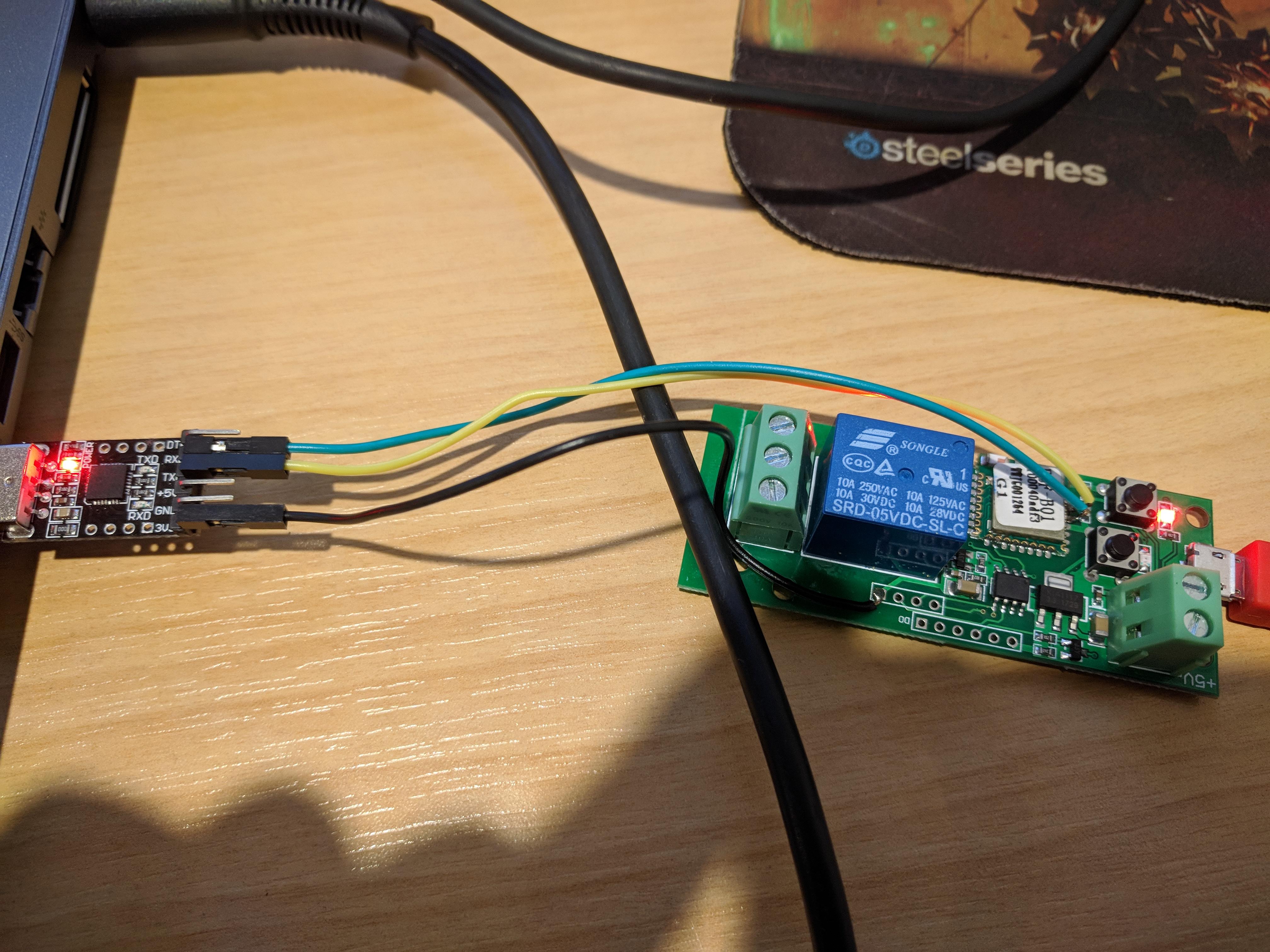
Here a pic of my setup. You can put the board in flash mode by pressing the TWO buttons simultaneously on power up, then press the outer button again and you will have the TWO led solid red. Now hold your needles on tx and rx pins of PSF-B01 and flash. I am only using ground wire of the ftdi, no power wire.

moonfarms
on 10 Aug 2017
@moonfarms
Hi Paul, thank you for your Picture. As i see you didnt solder the red Wire, 3,3 Volts ????
LurchiStromberg
on 10 Aug 2017
No, I am powering the unit trough the usb, black wire is for ground for tx rx
moonfarms
on 10 Aug 2017
@moonfarms
Oh... I read that 3,3 Volts is Urgent not to damage the EPS Chip at flashing...
Its pretty confusing if some Guys here tell to read Wikis, but at the End all do different stuff lol
But of course i am thankful to see, that there is also a more easy Way.
One last question about the Flash Mode. If I hold the 2 Buttons and Power the Board with the mini USB nothing happens that Moment. After I release the 2 Buttons the Relais start to pulse.
At the Moment i push the outer Button, both LEDs are solid.
Is that the Way it works?
LurchiStromberg
on 10 Aug 2017
The board will step down the usb 5v to 3.3 to power the esp chip
If the TWO leds are SOLID red you can flash. I am flashing with platformio
moonfarms
on 10 Aug 2017
@moonfarms
Thank you Paul for the hints, make Things more easy for me 👍
So if i dont need the 3,3 Volts from the FTDI i could also use an old USB-COM Stick?
Because i am still waiting for my Serial Converter from BG...
LurchiStromberg
on 10 Aug 2017
if your usb-com does usb to uart.....
AND TX RX IS 3.3v
moonfarms
on 10 Aug 2017
I use the one Attached.
I really dont know if it has UART. I used it to be able to connect a Dreambox to access Bootloader via Terminal.


LurchiStromberg
on 10 Aug 2017
Its pretty confusing if some Guys here tell to read Wikis, but at the End all do different stuff lol
Because - in the end - it is a ESP8285 chip you are working with. It doesn't matter if its on a Sonoff board or Nodemcu... it is always the same.
I flashed it months ago and I had no clue about possible button combination to force flash mode (it may also differ between 5V and 5V/12V model). So it is easier to just connect GPIO0 to Ground to force flash mode on every ESP8285 chip.
Maybe it is easier if you describe what u want to archieve with your Sonoff. In my case I use the Sonoff to open my garage and house door. It's important to note that your Relay will always trigger on powerup (ESPEASY Sonoff touch) which forced me to use my own sketch - so my door doesn't accidently open on power reset.
jktz90
on 10 Aug 2017
IMHO I think your usb to serial does not have a 3v output and you may fry the board
moonfarms
on 10 Aug 2017
@arendst
One Question to you also. Today my other sOnOffs arrived, the 90-250 V Version.
This ones are using the "normal" ESP 8266.
Your sonoff.bin is also for that Devices?
LurchiStromberg
on 10 Aug 2017
@moonfarms
Well i would connect the 5V Version to USB Charger as you do on your Pic and just use the RX,TX,GND from the USB-Com Adapter. So no Power comes thru it.
LurchiStromberg
on 10 Aug 2017
The latest sonoff.bin file is functional on ALL devices as it is compiled with Flash Mode Dout.
arendst
on 10 Aug 2017
@ lurchi IMHO the voltage of tx rx is relevant so if your usb com tx rx outputs 5v you are gambling
Let us know
moonfarms
on 10 Aug 2017
@moonfarms
No, I am powering the unit trough the usb, black wire is for ground for tx rx
Uhm....it was you who told me that you flash the Board with 5V Power from USB and GND, TX, RX from FTDI.
I also asked you and what i Quote was your Answer ;)
I think its a missunderstanding, for flashing you also use the 3,3 V from FTDI, even its not connected at your Picure, right?
LurchiStromberg
on 10 Aug 2017
FTDI comes in 2 versions, 5 and 3.3 v and that apply also to the voltage of tx rx, so if your ftdi is 5 v it also transmits receive in 5 v and as I mentioned the usb voltage supply to the esp is scaled down to 3.3v. If your ftdi supply 5v on tx side you may fry the board. So I am talking about the voltage of the tx rx lines
moonfarms
on 10 Aug 2017
@moonfarms
Like i said we have a missunderstanding mate!
The red wire on your Picture from FTDI Device goes to the Mini USB Port you plugged into the Board, right?
I thought you Power it with an other Charger, so no need to take the 3,3 Volts from the FTDI...
I am only surprised you only solder Ground on the Board and not also the 3,3 Volts...
LurchiStromberg
on 10 Aug 2017
my red wire is NOT connected ANYWHERE!!! I am telling you about the voltage of the TX RX wire, it comes in 2 VERSIONS also, 5V and 3.3V so if your FTDI is 5V power supply TX & RX is also 5V and if FTDI is 3.3V power supply and TX RX is 3.3 V
so my method uses the usb to power the sonoff but I am using 3.3 for tx rx
The ground wire is necessary for tx rx to work, if no ground wire to ftdi tx rx does NOT work
My USB is powered from a normal phone charger!
moonfarms
on 10 Aug 2017
Hi All, I've just flashed mine using @moonfarms method - it worked very well and took off all the headache I had before being afraid of too much soldering.
Now have a question: how to configure this module in sonoff? can I use Toggle button at all or just MQTT (preferred)? In the configuration I selected '1 channel' as type of device (name sounds relevant) but when I use e.g. Toggle, it switches the relay many times, not what I really want (as you may expect :)). Also what I observe is that after flashing, the micro usb power doesn't work (additional 5V socket to connect cables works fine) and I would be disappointed if I can't use my regular cable. My sonoff version is 5.5.2. All feedback will be highly appreciated.
//edit - I managed to do toggle with setting PulseTime - I'm happy with how it works.
still don't know why microusb power doesn't work. hints?
 witek1308
on 11 Aug 2017
witek1308
on 11 Aug 2017
you can set the fixed or inching by pressing the outer button.
I flashed 2 boards and did not have any issue with usb, power by usb still Working
moonfarms
on 11 Aug 2017
thanks for your response. which sonoff have you flashed with by the way? I use 5.5.2.
I observe the following behaviour (wrong for me, I need this to control garage door):
= with PulseTime 0
-- when 2nd button not pressed (inching mode) when I send power on command the relay switches ON 2x (which would mean it opens and closes the door) and the goes restart
-- when 2nd button pressed (fixed mode) it switches on the relay for ever which isn't good
= with PulseTime > 0 (let's say 0.5s)
-- when 2nd button not pressed - behaviour as above - 2x ON and then restart and instability
-- when 2nd button pressed - behaviour as expected - it emulates push button for 0.5s and all is fine BUT when there is loss of power and board boots up it switches automatically 2nd switch on boot -> sends a signal to my door to change state. This would lead to unexpected opening after power loss/back
my PowerOnState=0
I have no idea how to make it behave like normal inching mode, without sending a fake 'ON' when booting. Original software does what expected but I don't trust this chinese cloud (security and availability). I have 2nd board which I planned to flash tonight but given the above I'm not sure if I want to do this...
How do you configure it and how you use it? do you set in device type 1 Channel or maybe something else? which commands you use for inching? thanks!
witek1308
on 11 Aug 2017
I am using 5.5.0
I want to remote a Lego Duplo train.....
as for garage door see what @jktz90 has to say:
"In my case I use the Sonoff to open my garage and house door. It's important to note that your Relay will always trigger on powerup (ESPEASY Sonoff touch) which forced me to use my own sketch - so my door doesn't accidently open on power reset."
moonfarms
on 11 Aug 2017
Thanks @moonfarms i overlooked that comment. It is absolutely relevant to me. @jktz90 can you shed more light on how you resolved it? This will be very much appreciated!
witek1308
on 11 Aug 2017
@arendst
Moin Theo!
I just successfully flashed my ESP8285 with you latest sonoff.bin
Problem is like already talked about here, that inching not works with the 1 Channel 5V Board.
Is there hope that you can fix it or is it a Problem with Tasmota?
Oh....and do you know if there is somewhere the original *.bin to flash back the Stock Firmware?
EDIT:
Oh, just found that...
Does this
fix the Problem permanently ?
Its running now like it should
LurchiStromberg
on 12 Aug 2017
I have the 1 Channel Inching /Self-Locking, with the version PSF-B01, i flash with the lastest version of tasmota without problem (arduinoide and atom) but the problem appear when the firmware are loaded, run the new firmware connect to wifi, stay connected 10 seconds aprox, and the device reboot logging wdt reset .... (1,6) and freeze.
When disconect the device and connect again, the terminal dont show nothing ... and don't connect to my wifi.
pd: using the @moonfarms method i get: ets Jan 8 2013,rst cause:4, boot mode:(1,7)
and the same result
Any one have the same problem?
 osmassoglia
on 24 Aug 2017
osmassoglia
on 24 Aug 2017
Since this issue is still open, thought I'd post some detail to help along.
I have the same exact device (PSF-B01 inching relay), and was able to flash using the SonOTA method successfully.
I have also listed some of the configuration changes I did (referenced from this thread, so thank you to the one who posted the PulseTime URL).
In case it helps someone, here it is:
https://github.com/mirko/SonOTA/issues/41
Basically:
-> no soldering/desoldering.
-> Updated over the air (No need for serial communication)
-> Configured to get it working the way it should.
 ashwinbangalore
on 23 Oct 2017
ashwinbangalore
on 23 Oct 2017
hey Lurch can you advise what you do with this ---http://IPSONOFF/cm?cmnd=PulseTime2011
?
thanks in advance
 sabs01
on 5 Nov 2017
sabs01
on 5 Nov 2017
That's to set the duration for which the relay turns and stays on.
Essentially if you want to briefly turn on, and then off, the switch this
is what you use.
On Nov 4, 2017 10:48 PM, "sabs01" notifications@github.com wrote:
hey Lurch can you advise what you do with this ---http://IPSONOFF/cm?cmnd=
PulseTime2011
?
thanks in advance—
You are receiving this because you are subscribed to this thread.
Reply to this email directly, view it on GitHub
https://github.com/arendst/Sonoff-Tasmota/issues/453#issuecomment-341950792,
or mute the thread
https://github.com/notifications/unsubscribe-auth/AfDOuEOLZ5mJ2_-Sd7I4xTwRjSmzSBwUks5szUw3gaJpZM4NbfEK
.
ashwinbangalore
on 5 Nov 2017
Thanks
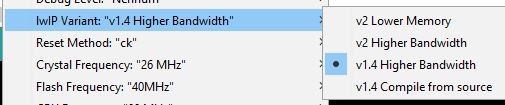
For those who need to set up inching on a sonoff 12v after flashing with tasmota I found this to work perfectly :
- Flash with 8266 arduino ide setup
- Login to the IP address and configure the sonoff as a WeMo mini (see settings image below)
- Go into console and use the following command PulseTime 10.10 (or whatever delay you want)
This sets up the delay for the on off switch to 1 sec (10ms)
Hope this helps ..
sabs01
on 10 Nov 2017
Hi to everyone!
I’m a beginner and I bought the board, based on the PSF-B01 itead ESP8285 module but I’m not able to use it by wifi. Noone of my device can find the module by wifi signal. May I do something before? Regards
 stepac
on 26 Nov 2017
stepac
on 26 Nov 2017
Hello!
I have Problems with the sOnOff 5V ESP8285 and Tasmota.
Everytime i reboot my Router (Fritzbox 7490) or make do a Device Search with the Echo Dot, all sOnOff 5V Moduls get a switch impulse.
So if my Router restarts, all Devices get a short pulse, thats annoying.
I use the sOnOff 5V for switching my Shutters (only 1 Wire connect)
So at every Pulse they open or close
That happens, when I restart the Router or make a Device search with Alexa
What went wrong in that?
LurchiStromberg
on 7 Mar 2018

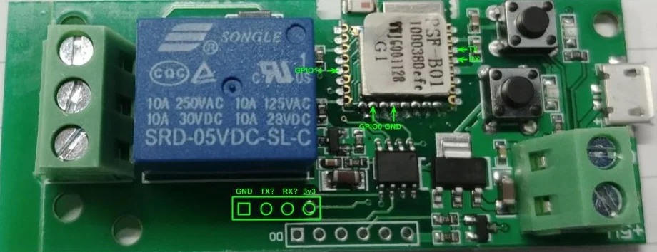
For what it's worth, here is the pinout representing how it works with original firmware. Basically the two buttons and mode LED is also available on the pins. The remaining 3 pins are not connected to anything.
 branob
on 7 Mar 2018
branob
on 7 Mar 2018
You can always consider to run your own sketch. The following sketch will
react upon receive an UDP packet with "n", so you can control your shutters
via smartphone or FHEM
include
include
include
include
include
include
include
include
include
include
include
//UDP Config
WiFiUDP Udp;
unsigned int localUdpPort = 4210;// local port to listen on
unsigned int remoteUdpPort = 4210;// local port to listen on
char incomingPacket[255];// buffer for incoming packets
char replyPacekt[] = "Hi there! Got the message :-)";// a reply string to
send back
const char* password = "xx";
const char* ssid = "xx";
IPAddress ipa(192, 168, 178, 1);
int count = 0;
void setup() {
digitalWrite (12, LOW);
delay(100);
pinMode (12, OUTPUT);
Serial.begin(9600);
Serial.print("Starte...");
WiFi.begin(ssid, password);
while (WiFi.status() != WL_CONNECTED)
{
delay(500);
}
Udp.begin(localUdpPort);
}
void loop() {
if (WiFi.status() != WL_CONNECTED)
{
Wifistart();
}
int packetSize = Udp.parsePacket();
if (packetSize)
{
// receive incoming UDP packets
int len = Udp.read(incomingPacket, 255);
if (len > 0)
{
  incomingPacket[len] = 0;
if (incomingPacket[0] == 'n') {
// DO WHATEVER YOU WANT IF YOUR UDP PACKET CONTAINS n AT POSITION 0
// EG digitalWrite (12, LOW);
}
}
}
delay(0);
count ++;
if(count == 333){
wakeup();
}
delay(150);
}
void Wifistart(){
WiFi.begin(ssid,password);
delay(5000);
}
void wakeup(){
count = 0;
unsigned int udpR=2391;
byte message[1];
message[0] = 1;
Udp.beginPacket(ipa,udpR);
Udp.write("1");
Udp.endPacket();
yield();
}
Am Mi., 7. März 2018 um 13:34 Uhr schrieb LurchiStromberg <
[email protected]>:
Hello!
I have Problems with the sOnOff 5V ESP8285 and Tasmota.
Everytime i reboot my Router (Fritzbox 7490) or make do a Device Search
with the Echo Dot, all sOnOff 5V Moduls get a switch impulse.
So if my Router restarts, all Devices get a short pulse, thats annoying.I use the sOnOff 5V for switching my Shutters (only 1 Wire connect)
So at every Pulse they open or closeThat happens, when I restart the Router or make a Device search with Alexa
What went wrong in that?
—
You are receiving this because you were mentioned.
Reply to this email directly, view it on GitHub
https://github.com/arendst/Sonoff-Tasmota/issues/453#issuecomment-371124610,
or mute the thread
https://github.com/notifications/unsubscribe-auth/AcLgQO3PexF2bmRC2gUPHQIWe4zP_tnjks5tb9PLgaJpZM4NbfEK
.
jktz90
on 8 Mar 2018
Can somebody show the pin out for flashing of the new board of 1 Channel Switch 5V / 12V,
the board as shown in the pic ed1402 published on May 16 2017
 ronwar
on 23 Mar 2018
ronwar
on 23 Mar 2018
Hey guys, I got another flavour of PSF-B01 (ESP8285) board from Aliexpress: https://www.aliexpress.com/item/AC-220V-WIFI-Relay-Switch-Module-Low-Power-Jog-Mode-Phone-Remote-Timer-Control-For-Wireless/32828422609.html?spm=a2g0s.9042311.0.0.alwtoU


Tried to flash by connecting directly to the chip using this pinout, but no success:
Always getting:
warning: espcomm_sync failed
error: espcomm_open failed
error: espcomm_upload_mem failed
error: espcomm_upload_mem failed
Any ideas where to start?
 TSparkas
on 31 Mar 2018
TSparkas
on 31 Mar 2018
U tried basics things like switching RX / TX?
2018-03-31 18:33 GMT+02:00 TSparkas notifications@github.com:
Hey guys, I got another flavour of PSF-B01 (ESP8285) board from
Aliexpress: https://www.aliexpress.com/item/AC-220V-WIFI-Relay-
Switch-Module-Low-Power-Jog-Mode-Phone-Remote-Timer-Control-For-Wireless/
32828422609.html?spm=a2g0s.9042311.0.0.alwtoU[image: img_20180331_192348]
https://user-images.githubusercontent.com/32818805/38165312-23f60b42-351a-11e8-947b-07cda154dd2c.jpg
[image: img_20180331_192404]
https://user-images.githubusercontent.com/32818805/38165317-2b1ebb4e-351a-11e8-9bd3-8ba30451517e.jpgTried to flash by connecting directly to the chip using this pinout, but
no success:
[image: 29122265-fc2e6cbe-7d11-11e7-89d5-3e6db378b2fc]
https://user-images.githubusercontent.com/32818805/38165324-3d3a3c5e-351a-11e8-893a-5dbd1bd316d2.jpgAlways getting:
warning: espcomm_sync failed
error: espcomm_open failed
error: espcomm_upload_mem failed
error: espcomm_upload_mem failedAny ideas where to start?
—
You are receiving this because you were mentioned.
Reply to this email directly, view it on GitHub
https://github.com/arendst/Sonoff-Tasmota/issues/453#issuecomment-377705468,
or mute the thread
https://github.com/notifications/unsubscribe-auth/AcLgQOFqiMIKaLx7DvW5AEI6-FEZJA_jks5tj6_QgaJpZM4NbfEK
.
jktz90
on 31 Mar 2018
Yes, tried these options:
1) Switching RX/TX
2) Powering 3.3V/ground just from FTDI (to VCC-3V3 and GND pins near RX/TX)
3) Connecting just RX/TX from FTDI and powering via the board (then relay is constantly clicking, so I assume the chip is entering flash mode?)
GPIO0 was always connected to ground
The board has one button, also tried to power the board while pressing the button.
So far ran out of options what is wrong.
TSparkas
on 31 Mar 2018
Be sure you connect ground to GPIO0 before powering up the board. Also are
you sure you found the correct pin outs for GPIO0, TX / RX? The layout you
posted is correct, try to get the right orientation of the pinouts with the
following picture:
https://user-images.githubusercontent.com/29548608/29034982-580482a4-7b9a-11e7-901b-a8cf83351804.JPG
Are you sure you want to use that board vor 230V? It looks clumped up.
There are better 230V AC switches from Sonoff.
2018-03-31 19:00 GMT+02:00 TSparkas notifications@github.com:
Yes, tried these options:
- Switching RX/TX
- Powering 3.3V/ground just from FTDI
- Connecting just RX/TX from FTDI and powering via the board (then
relay is constantly clicking, so I assume the chip is entering flash mode?)GPIO0 was always connected to ground
The board has one button, also tried to power the board while pressing the
button.So far ran out of options what is wrong.
—
You are receiving this because you were mentioned.
Reply to this email directly, view it on GitHub
https://github.com/arendst/Sonoff-Tasmota/issues/453#issuecomment-377707513,
or mute the thread
https://github.com/notifications/unsubscribe-auth/AcLgQNc-ZXzzhgN6noOkKsPqySvFto6yks5tj7YkgaJpZM4NbfEK
.
jktz90
on 31 Mar 2018
Yes, the orientation looks right.
Shall I connect ground to GPIO0 only while powering the board or it can stay connected later on?
The reason I haven't used Sonoff, because this is very compact board and fits into European light switch box, while Sonoff doesn't fit. If you have better alternatives, I am interested :)
TSparkas
on 31 Mar 2018
Try connecting it only during power up. Also try uploading a sketch with
the Arduino IDE and select the ESP8285 board.
Keep in mind ure using 230V here.. so in case your relais does not work
accordingly (for example switching on / off rapidly) it could start burning
(especially if the solder lines are not seperated correctly). Especially if
you use it within the wall it could heat up. Its a pretty solution but also
high risk . Alternative would be RF controllable switches (maybe eben
WiFi?) which you buy in germany with CE approval.
2018-03-31 19:49 GMT+02:00 TSparkas notifications@github.com:
Yes, the orientation looks right.
Shall I connect ground to GPIO0 only while powering the board or it can
stay connected later on?The reason I haven't used Sonoff, because this is very compact board and
fits into European switch socket box, while Sonoff doesn't fit. If you have
better alternatives, I am interested :)—
You are receiving this because you were mentioned.
Reply to this email directly, view it on GitHub
https://github.com/arendst/Sonoff-Tasmota/issues/453#issuecomment-377710865,
or mute the thread
https://github.com/notifications/unsubscribe-auth/AcLgQLJE2A2XR1PS4_o-Eeo87R7p2uKAks5tj8GdgaJpZM4NbfEK
.
jktz90
on 1 Apr 2018
@TSparkas - I'm Having a heck of a time flashing the PSF-B01, any luck?
 rmarkle
on 30 Apr 2018
rmarkle
on 30 Apr 2018
No luck so far :( Will try again during the upcoming weekend.
TSparkas
on 30 Apr 2018
@TSparkas I FINALLY figured it out. Make sure you attach your ground from your FTDI to the ground on your board.
I had some issues using a mac because of the default FTDI drivers (on second thought, maybe it's because i didn't use the ground.. idk)
This was using Arduino IDE on a windows 7 Machine.
Make sure both FTDI Board and Relay Board are disconnected from everything.
Anyway, Here's the steps i took (no solder):
- Prepared the FTDI - I placed the jumper wires on the RX, TX and Ground pins on the FTDI board and plugged in the FTDI board to your computer.
- Attached FTDI ground to the board's ground
- Put the relay board in flash mode by holding the two buttons, plugging in the micro usb, released the two buttons (you should hear the relay click on and off repeatedly) and hitting the "bottom" button (the button closest to the edge of the board). You should see two LEDS remain lit.
- Started upload process in ArduinoIDE.
- Quickly held the TX to pin 4 and the RX to pin 3 on the chip.
You should see an uploading progress in the ArduinoIDE so stay very still with those tx/rx pins.
That should be it! The board will automatically restart and attempt to connect to the wifi you setup in the tasmota code.
Let me know if you need any other help.
rmarkle
on 2 May 2018
I've got one of these 5V devices and I managed to install Tasmota fw by following @rmarkle 's guide (thanks!) and this video. Power can be provided via the micro USB interface, while only the TX and RX pins must be connected manually to esp pins #3 and respectively #4.
Unfortunately the device does not work in inching mode; _the relay is triggered approx. 4-6 times in a row and immediately the module restarts_; the wifi is available few seconds later. Sometimes it remains frozen and it needs a cold reboot (plug-out / plug-in the USB cable).
However, I believe one can easily simulate the inching function by simply triggering a sequence of power on / power off commands via mqtt.
This turns the device into a simple Sonoff basic, from the functionality perspective.
There is also the (somehow useless) alternate option to configure the device as ElectroDragon, in which case two switches are available:
- sw1 - controls the LED near the on/off switch
- sw2 - controls the onboard relay.
Either way, the device works only in normal power on/off mode. If one presses sw2 and then tries to use the web/mqtt interface to fire up commands, the module will go haywire as depicted above (see _italic_ text).
 tlc76
on 23 May 2018
tlc76
on 23 May 2018
In case someone wants to revert to the original Itead firmware, I've dumped the esp binary before overwriting it with Tasmota.
tlc76
on 23 May 2018
You ca use this switch as same of Sonoff 5v: Geekcreit® USB 5V DIY 1 Channel Jog Inching Self-locking WIFI Wireless Smart Home Switch Socket APP Remote Control
I flashed it soldering some wires in ESP module as photos show here.
 PauloPC
on 30 May 2018
PauloPC
on 30 May 2018
Am having the same errors as others above:
warning: espcomm_sync failed
error: espcomm_open failed
error: espcomm_upload_mem failed
error: espcomm_upload_mem failed
Have tried a number of methods, interestingly, I seem to have issues with the GND connection, if I leave it off, I see activity led's on the uart lighting up a wee bit, but if I plug the GND in, I get no activity on the led's, attached a picture of the board while in flashing mode, can anyone see any problems?
 syphe
on 8 Jun 2018
syphe
on 8 Jun 2018
I flash by connecting directly to the chip using this pinout

https://user-images.githubusercontent.com/32818805/38165324-3d3a3c5e-351a-11e8-893a-5dbd1bd316d2.jpg
PauloPC
on 8 Jun 2018
Even I send a command CMD: PowerOnState
MQT: stat/sonoff5V/RESULT = {"PowerOnState":0} As result
Ever time I Power on it it comes as Power ON.
Some one has a solution for this?
PauloPC
on 8 Jun 2018
@syphe How exactly did u put your Sonoff into flash mode? Ground has to be connected to GPIO0 upon power up.
Select ESP 8285 generic in Ardunio IDE and try flashing. If it fails, try swapping RX/TX if ure not sure if connected correctly (RX TX / TX RX).
If I remember correctly I had some problems with the inching mode. Try disabling it (LED turns off @ USB port) and try putting it into flash mode again. The LED at the relais should be on permanetly.
jktz90
on 8 Jun 2018
Managed to get it working finally, first tried a raspberry pi I had to see if my serial adapter was the cause, then after that still didn't work ended up just soldering all the required points to the board as below.
I think what finally worked was supplying 3.3v to the board, as giving it 5v from usb didn't work, but as soon as I have it 3.3v the flashing process went through perfectly.

Note: 3.3v is disconnected in the picture, was connected to the top right header pin in the image, I was disconnecting everything at the time, but figured I should take a picture just to show what worked for me.
syphe
on 10 Jun 2018
I still don't have this new device (yet), but I am sure it is a derivative work of a board that used to control the relay through a chain, in which the ESP82xx sent a serial command to the chip STCSTC15F104, that activated the relay. The STC15F104 had a proprietary firmware to control the relay, but had the following serial commands to enable the relay control (using 9600,N,8,1)
0xA0 0x01 0x01 0xA2 => relay on
0xA0 0x01 0x00 0xA1 => relay off
This means that for boards that still have the chip STC15F104 (I have one that has is controlled by an ESP01 on board) Tasmota could give the correct command on the serial port to enable/disable the relay.
 antimix
on 24 Jun 2018
antimix
on 24 Jun 2018
Thanks for the great help, so I managed to flash my "1Channel Inching/Locking 5V/12V Sonoff "with Tasmota which is working fine but I want to install a sensor to detect if my garage door is open, so to do this I need a GPIO14 but I cant find on this board!
So is there a GPIO14 or not?
Thanks,

 senadaruc
on 30 Jun 2018
senadaruc
on 30 Jun 2018
@senadaruc see branob commented on 7 Mar
https://user-images.githubusercontent.com/5835733/37117875-6ce0241c-2220-11e8-8a70-6b4a9b67a025.jpg
PauloPC
on 1 Jul 2018
Thanks, PauloPC so this device doesn't have GPIO14, I need to go with SV version.
senadaruc
on 1 Jul 2018
@senadaruc Actually I believe GPIO14 is the 5th pin from the top on the left side of the chip.
(I didn't create this image & haven't tested for GPIO14, but it's not the only picture I've seen that shows GPIO14 in that same location.)
 KBrownConsulting
on 4 Aug 2018
KBrownConsulting
on 4 Aug 2018
Hi,
Closing issue as there is no activity in this thread. Please, if you need more help, ask to reopen it.
 ascillato2
on 4 Sep 2018
ascillato2
on 4 Sep 2018
Can this issue be reopened, please?
I have trouble flashing a Sonoff 1CH. My board is based on the PSF-B01 (PSF-B85). On the board I found this number: 150318AP130-181031.
I believe I followed all the instructions and recommendations mentioned in this github issue, without success. May be I am doing something wrong or may be my board needs a slidely different approach?
I did solder wires to the PSF-B01:
- TxD (left side, 3rd pin from below)
- RxD ( left side, 4th pin from below)
- GPIO0 (upper side, 2nd from the right)
And I did solder a 4 pin connector in the middle of the board (difficult to see on the photo, sorry):
- GND upper pin
- n/a
- n/a
- 3v3 lower pin

After soldering the board is still working (it is responding to the buttons, the leds are working and the relay is clicking).


I do have experience in soldering wires on to chip pins and I was able to flash the Tasmota firmware onto other Sonoff boards using VSCODE + PlatformIO plugin (running on Linux) and a CH340G USB.

To flash to board I took to following steps:
- connect TxD board to CH340G RxD
- connect RxD board to CH340G TxD
- connect GND board to CH340G GND
- connect GPIO0 board to GND board (to trigger flash mode when the board is powered on)
- insert CH340G USB into laptop
- connect 3v3 board to CH340G 3v3
- wait a few seconds
- disconnect the GPIO0 board from GND (the board should now be in flash mode)
- noticed a flashing led on the CH340, like is normal when I flash other boards
- start flashing
- instead of two leds on the CH340G should flash, only one led flashes.
- after some seconds the flash process stops with an error:
Flash log:
Compiling .pioenvs/sonoff-basic/src/sonoff.ino.cpp.o
Linking .pioenvs/sonoff-basic/firmware.elf
Retrieving maximum program size .pioenvs/sonoff-basic/firmware.elf
Building .pioenvs/sonoff-basic/firmware.bin
Checking size .pioenvs/sonoff-basic/firmware.elf
Memory Usage -> http://bit.ly/pio-memory-usage
DATA:    [======    ]  55.4% (used 45380 bytes from 81920 bytes)
PROGRAM: [====      ]  43.9% (used 449140 bytes from 1023984 bytes)
Configuring upload protocol...
Looking for upload port...
Use manually specified: /dev/ttyUSB0
Uploading .pioenvs/sonoff-basic/firmware.bin
warning: espcomm_sync failed
error: espcomm_open failed
error: espcomm_upload_mem failed
*** [upload] Error 2
Any feedback is welcome!
 tedsluis
on 5 Jan 2019
tedsluis
on 5 Jan 2019
Same Issue to me, is there any help outside?
 owieder
on 8 Jan 2019
owieder
on 8 Jan 2019
@tedsluis @owieder
For support on flashing, please address this to the Tasmota Support Chat. Thanks
 ascillato
on 8 Jan 2019
ascillato
on 8 Jan 2019
For support on flashing, please address this to the Tasmota Support Chat. Thanks
@ascillato: Thnx for your advise!
tedsluis
on 8 Jan 2019
Hello,
i am new to this forum and programming in general but following this tutorial i managed to flash my 1 ch sonoff and it is working. I know how it is hard sometimes to find information about all stepsHere is instruction how i did it.
- i downloaded ESPEasy_mega-20190110, extracted to folder /ESPEasy_mega-20190110
- i downloaded sonoff.bin from tasmota, place into folder /ESPEasy_mega-20190110
- Hardware setup. First picture FTDI232 setup and wires, second picture 1CH bord pin setup. FTDI 232 power mode must be 3.3V.
- hold both buttons on 1CH board while insert FTDI232 usb to computer. Release buttons right after insert usb into pc. Now 1CH board must be in flashing mode.
- Run FlashESP8266.exe, select correct port and choose sonoff.bin in menu.
- Put pins on board and hold them. You must hold pins very steady on board 5 pin - RX, 6 pin - TX. Hit flash and process should be started. It might not work from first time, just try few times.
I hope this will be helpful.
Update: after flashing to tasmota, 1CH relay started to swich on/off randomly. This happens all the time then relay looses wifi connection and restores it. I could not find any reliable solution for this problem.
Only solution i found and it is working 100% time is switch to ESPURNA 1ch relay firmware. Now i'm testing ESPURNA for few days and absolutely happy with results.

 johnsnow0
on 18 Jan 2019
johnsnow0
on 18 Jan 2019
I can flash custom firmware now.
Use unofficial PL2302: failed (the voltage of TX and RX may be incorrect 3.3V)
After use FTDI, it is ok and there is a key point. That is removing the power 3.3 of sonoff while retrying.
 tsunglung
on 21 Jan 2019
tsunglung
on 21 Jan 2019
hold down the B1 button and connect the USB voltage.
The LED diode next to the button must be on.
Permanent relay switching is deactivated
ESPEasy:
Rules:
// Relay GPIO 12
// KEY GPIO 0
on Button#State=1 do
if [Relay#State]=1
gpio 12,0
else
gpio,12,1
endif
endon
 leonardofibonacci
on 8 Apr 2019
leonardofibonacci
on 8 Apr 2019
ESPURNA 1ch relay firmware
could you please refer to ESPURNA binary which have you used?
I tried this one espurna-1.13.5-itead-1ch-inching.bin and it randomly switches as well
 scasic
on 11 Apr 2019
scasic
on 11 Apr 2019
i used espurna-1.13.3-itead-1ch-inching.bin for 1ch switch, for my Sonoff 4Ch pro i used espurna-1.13.5-itead-sonoff-4ch-pro.bin and i can confim that it is working properly. No random switching.
BTW, in espurna settings you have to check that device always start in OFF mode. Maybe this was reason for you.
johnsnow0
on 11 Apr 2019
you have to check that device always start in OFF mode
thank you for feedback. I've just tried to flash tasmota - it's much less stable than espurna, on toggle command it triggers relay multiple times and disconnects from wifi.
As for espurna I tried with OFF mode but it also triggers relay multiple times in a row. But at least it doesn't lose wifi connectivity
scasic
on 11 Apr 2019
This is my espurna Settings, i have no idea How to help if this will not work.
Sent from my iPhone
On 11 Apr 2019, at 22:18, scasic notifications@github.com wrote:
you have to check that device always start in OFF mode
thank you for feedback. I've just tried to flash tasmota - it's much less stable than espurna, on toggle command it triggers relay multiple times and disconnects from wifi.
As for espurna I tried with OFF mode but it also triggers relay multiple times in a row. But at least it doesn't lose wifi connectivity
—
You are receiving this because you commented.
Reply to this email directly, view it on GitHub, or mute the thread.
johnsnow0
on 11 Apr 2019
finally i got it work with tamosta:
- using "model change" button switch relay to simple switch mode (led is always on)
- type in GUI console "PulseTime 30"
I know it's just software emulation of inching mode, but at least it now works as expected. Without sporadic triggering and restarts, on startup relay keeps calm.
However there is an issue with manual board restart, when i call restart from GUI it triggers relay before getting reset. By the way same behavior on espurna
scasic
on 12 Apr 2019
Hi Guys!
One Question to the 5V 1CH Modul.
What is the Command to change the Delay of the Relay?
I like to change it to 2 Seconds, so the Relay keeps "on" for that time...
LurchiStromberg
on 27 Jun 2019
LurchiStromberg, If your using android app eWeLink to control your switch, you can set it by going to settings of that switch.. The three little dot in the circle on the right. Click Settings. Scroll down to Inching and turn it on. There you can change the Inching duration to what you need. Hope that helps. >>DW
 dwetchells
on 28 Jun 2019
dwetchells
on 28 Jun 2019
well thank you mate, but we are here at Tasmota... So of course i installed Tasmota on the 1CH Modul...
I am sure there is a Command i can type in the Console...
Problem only is........which one change the Delay of the Relay...
LurchiStromberg
on 28 Jun 2019
 joba-1
on 28 Jun 2019
joba-1
on 28 Jun 2019
https://github.com/arendst/Sonoff-Tasmota/wiki/Commands#pulsetime
Thanks Mate!
I tried that already but dont get clever out of it
If i put PulseTime 2 i get the following output:
stat/Markise/RESULT = {"PulseTime1":"2 (Active 0)"}
What does "Active 0" mean?
Puls Time is set but not active?
LurchiStromberg
on 28 Jun 2019
Turn on your relay. After 2 seconds it will turn off.
The 'active 0' part means the remaining time for turning off. For example, if you give 60 seconds, you can ask Tasmota with just the command pulsetime1 (no spaces) to know how much time is remaining.
If you need further assistant, please address this to the Tasmota support chat. Github issues are for Tasmota Software Bug reporting with the template completed. Thanks
ascillato
on 28 Jun 2019
I have an issue with this relay when no wifi signal. I hope it is wrong configuration only but I don't know what combination of settings would resolve it. The problem is that when wifi signal is lost, the relay restarts but restarts and powers on. Since it is connected to a gate, it opens the gate. Single opening wouldn't be a problem but in case of longer wifi unavailability (sometimes router hangs) it periodically restarts and opens the gate on and on.
I'm on 6.6.0 (but on any SW before there was same behavior), my settings are: power off on startup, there is no PowerRetain from what I see, switchtype used to be 0 but I changed it to reversed pushbutton with PulseTime of 5. Any ideas what I can change?
witek1308
on 12 Aug 2019
Check the wiki FAQ entry on ghosting.
Please address your questions to the Tasmota Support Discord Chat. The chat is a better and more dynamic channel for helping you. Github issues are best used for Tasmota _software feature requests and bug reporting_. Troubleshooting and setup assistance is more effective using an interactive forum.
Please check the Contributing Guideline and Policy and the Support Guide.
Thanks.
Support Information
See Wiki for more information.
See Chat for more user experience.
See Community for forum.
See Code of Conduct
 meingraham
on 12 Aug 2019
meingraham
on 12 Aug 2019
I wanted to reopen this (it can be immediately reclosed) JUST because I know of no other place to post this valuable information, and in my pursuit of the information I found no other place online where it is properly discussed!!
Here is how to flash your PSF-B01.
NO HARDWARE MODIFICATIONS ARE NECESSARY.
(Note I have the AC/DC 7-32V module and I will be using it as a thermostat override to power on my HVAC fan using sonoff. This should work fine for the other version on this thread too)
Use this pinout;

Use this flash boot method (press both buttons while powering it. Both LEDs need to come on.
You can flash Tasmota now.
Once booted, set it to module "1 channel (12)" in the included module list (no external template is needed).
VERY IMPORTANT
SetOption13 1
This will disable the "triple press" functionality that usually reboots ESP8266 into SmartConfig Mode.
After that, you can select via the hardware button if you want inching or locking latch, and you are good to go!
I hope this message saves someone A LOT of time. I took me quite a while to figure out why the module was going haywire.
 ryaske
on 3 Nov 2019
ryaske
on 3 Nov 2019
Seems like i have another new layout ...
Tried several things to enter Flash Mode, without luck:
- Pushed both buttons and connect USB --> No LED will tun on
- Connected GPIOO with GND of PI --> Devies is starting as usual ( 1 LED is blinking )
- Tried some Pins on the bottom (the right and left one) ---> right: No LED, left: booting up as usual
Does someone have an idea?
 Pingbo
on 31 Jan 2020
Pingbo
on 31 Jan 2020
Seems like i have another new layout ...
Tried several things to enter Flash Mode, without luck:
- Pushed both buttons and connect USB --> No LED will tun on
- Connected GPIOO with GND of PI --> Devies is starting as usual ( 1 LED is blinking )
- Tried some Pins on the bottom (the right and left one) ---> right: No LED, left: booting up as usual
Does someone have an idea?
I have same board aslo.. did you find a way to flash it?
 negmos
on 21 Feb 2020
negmos
on 21 Feb 2020
Hi. From what seen on google you make soldering connections on the PSF-BO1 chip. Connecting tx & rx Pins 3 & 4 on the top right side near the buttons. Just google Flash PSF-B01. Lots of articles on this
Sent from my iPad
On Feb 21, 2020, at 11:23 AM, Mohamed Negm notifications@github.com wrote:
Seems like i have another new layout ...
[IMG_20200131_171510]https://eur02.safelinks.protection.outlook.com/?url=https%3A%2F%2Fuser-images.githubusercontent.com%2F7976657%2F73555428-e8600980-444d-11ea-8d63-254fa4ed1dde.jpg&data=02%7C01%7C%7C01f8b8f5fd9041b527e408d7b6fb28d6%7C84df9e7fe9f640afb435aaaaaaaaaaaa%7C1%7C0%7C637179062140012195&sdata=XnWgiCSvCKIHX2AIE%2Bf1YE9XJGAxkKcjqxA68yCKQYQ%3D&reserved=0
Tried several things to enter Flash Mode, without luck:
- Pushed both buttons and connect USB --> No LED will tun on
- Connected GPIOO with GND of PI --> Devies is starting as usual ( 1 LED is blinking )
- Tried some Pins on the bottom (the right and left one) ---> right: No LED, left: booting up as usual
Does someone have an idea?
I have same board aslo.. did you find a way to flash it?
—
You are receiving this because you commented.
Reply to this email directly, view it on GitHubhttps://eur02.safelinks.protection.outlook.com/?url=https%3A%2F%2Fgithub.com%2Farendst%2FTasmota%2Fissues%2F453%3Femail_source%3Dnotifications%26email_token%3DAJTJEZH3BHFZRJOFMYYWFJDREAL2JA5CNFSM4DLN6EFKYY3PNVWWK3TUL52HS4DFVREXG43VMVBW63LNMVXHJKTDN5WW2ZLOORPWSZGOEMTTYSA%23issuecomment-589773896&data=02%7C01%7C%7C01f8b8f5fd9041b527e408d7b6fb28d6%7C84df9e7fe9f640afb435aaaaaaaaaaaa%7C1%7C0%7C637179062140022205&sdata=uJlMXDygzh7xaw9lV0H%2F5aIj6rgzWRpuRSrz3xfabg4%3D&reserved=0, or unsubscribehttps://eur02.safelinks.protection.outlook.com/?url=https%3A%2F%2Fgithub.com%2Fnotifications%2Funsubscribe-auth%2FAJTJEZBZF3UGHRY4TQPCZELREAL2JANCNFSM4DLN6EFA&data=02%7C01%7C%7C01f8b8f5fd9041b527e408d7b6fb28d6%7C84df9e7fe9f640afb435aaaaaaaaaaaa%7C1%7C0%7C637179062140032210&sdata=%2BmB%2FO%2FSKfdPURvXG3kTx4jvZBMUEGUx%2BOd%2Fq%2FGJKv0g%3D&reserved=0.
dwetchells
on 22 Feb 2020
Once booted, set it to module "1 channel (12)" in the included module list (no external template is needed).
VERY IMPORTANT
SetOption13 1This will disable the "triple press" functionality that usually reboots ESP8266 into SmartConfig Mode.
thank you SOOOOO much for "SetOption13 1" fixed my all problems
 armdan
on 21 Apr 2020
armdan
on 21 Apr 2020
Hello I plan to add an external antenna for the attached board. Does anyone know where to solder the external antenna lead?

 Emile7
on 16 Jul 2020
Emile7
on 16 Jul 2020
A picture of the bottom may help.
El jue., 16 jul. 2020 a las 10:59, Emile7 (notifications@github.com)
escribió:
Hello I plan to add an external antenna for the attached board. Does
anyone know where to solder the external antenna lead?
[image: 7c09ea96-3a7b-11e7-8498-f53947794f2f]
https://user-images.githubusercontent.com/68385687/87679715-2d21f780-c785-11ea-8fc6-cecaa6870bf5.jpg—
You are receiving this because you are subscribed to this thread.
Reply to this email directly, view it on GitHub
https://github.com/arendst/Tasmota/issues/453#issuecomment-659430654,
or unsubscribe
https://github.com/notifications/unsubscribe-auth/ACXBW4PGZE4XKGB54G2KF7LR34BS7ANCNFSM4DLN6EFA
.
 lalo-uy
on 16 Jul 2020
lalo-uy
on 16 Jul 2020
A picture of the bottom may help. El jue., 16 jul. 2020 a las 10:59, Emile7 (notifications@github.com) escribió:
…
Hello I plan to add an external antenna for the attached board. Does anyone know where to solder the external antenna lead? [image: 7c09ea96-3a7b-11e7-8498-f53947794f2f] https://user-images.githubusercontent.com/68385687/87679715-2d21f780-c785-11ea-8fc6-cecaa6870bf5.jpg — You are receiving this because you are subscribed to this thread. Reply to this email directly, view it on GitHub <#453 (comment)>, or unsubscribe https://github.com/notifications/unsubscribe-auth/ACXBW4PGZE4XKGB54G2KF7LR34BS7ANCNFSM4DLN6EFA .

Emile7
on 17 Jul 2020
That module has a ceramic antena, the white component in the corner.
You may need to remove it in order to attach a different one.
Youcan connect also connect on module pin 1.
El El vie, 17 de jul. de 2020 a la(s) 01:17, Emile7 <
[email protected]> escribió:
A picture of the bottom may help. El jue., 16 jul. 2020 a las 10:59,
Emile7 ([email protected]) escribió:
… <#m_7834619719896913155_m_8465963238316833967_>
Hello I plan to add an external antenna for the attached board. Does
anyone know where to solder the external antenna lead? [image:
7c09ea96-3a7b-11e7-8498-f53947794f2f]
https://user-images.githubusercontent.com/68385687/87679715-2d21f780-c785-11ea-8fc6-cecaa6870bf5.jpg
— You are receiving this because you are subscribed to this thread. Reply
to this email directly, view it on GitHub <#453 (comment)
https://github.com/arendst/Tasmota/issues/453#issuecomment-659430654>,
or unsubscribe
https://github.com/notifications/unsubscribe-auth/ACXBW4PGZE4XKGB54G2KF7LR34BS7ANCNFSM4DLN6EFA
.[image: back]
https://user-images.githubusercontent.com/68385687/87748007-76ae2900-c7fd-11ea-9cce-c9b5c07f2444.jpeg—
You are receiving this because you commented.
Reply to this email directly, view it on GitHub
https://github.com/arendst/Tasmota/issues/453#issuecomment-659836281,
or unsubscribe
https://github.com/notifications/unsubscribe-auth/ACXBW4IY2SWXXL4FNDVTE7DR37GD5ANCNFSM4DLN6EFA
.
lalo-uy
on 17 Jul 2020
That module has a ceramic antena, the white component in the corner. You may need to remove it in order to attach a different one. Youcan connect also connect on module pin 1. El El vie, 17 de jul. de 2020 a la(s) 01:17, Emile7 < [email protected]> escribió:
…
A picture of the bottom may help. El jue., 16 jul. 2020 a las 10:59, Emile7 @.*) escribió: … <#m_7834619719896913155_m_8465963238316833967_> Hello I plan to add an external antenna for the attached board. Does anyone know where to solder the external antenna lead? [image: 7c09ea96-3a7b-11e7-8498-f53947794f2f] https://user-images.githubusercontent.com/68385687/87679715-2d21f780-c785-11ea-8fc6-cecaa6870bf5.jpg — You are receiving this because you are subscribed to this thread. Reply to this email directly, view it on GitHub <#453 (comment) <#453 (comment)>>, or unsubscribe https://github.com/notifications/unsubscribe-auth/ACXBW4PGZE4XKGB54G2KF7LR34BS7ANCNFSM4DLN6EFA . [image: back] https://user-images.githubusercontent.com/68385687/87748007-76ae2900-c7fd-11ea-9cce-c9b5c07f2444.jpeg — You are receiving this because you commented. Reply to this email directly, view it on GitHub <#453 (comment)>, or unsubscribe https://github.com/notifications/unsubscribe-auth/ACXBW4IY2SWXXL4FNDVTE7DR37GD5ANCNFSM4DLN6EFA .
You mean connect to pin1 without removing the ceramic antenna?
Emile7
on 17 Jul 2020
No, that will produce an impedance mismatching. Antenas are tricky to adapt.
Yor external one may be different impedance than the ceramic one. You will
need to adjust with a LC netwok.
El El vie, 17 de jul. de 2020 a la(s) 13:31, Emile7 <
[email protected]> escribió:
That module has a ceramic antena, the white component in the corner. You
may need to remove it in order to attach a different one. Youcan connect
also connect on module pin 1. El El vie, 17 de jul. de 2020 a la(s) 01:17,
Emile7 < [email protected]> escribió:
… <#m_7700677667163616990_>
A picture of the bottom may help. El jue., 16 jul. 2020 a las 10:59,
Emile7 @.*) escribió: …
<#m_7834619719896913155_m_8465963238316833967_> Hello I plan to add an
external antenna for the attached board. Does anyone know where to solder
the external antenna lead? [image: 7c09ea96-3a7b-11e7-8498-f53947794f2f]
https://user-images.githubusercontent.com/68385687/87679715-2d21f780-c785-11ea-8fc6-cecaa6870bf5.jpg
— You are receiving this because you are subscribed to this thread. Reply
to this email directly, view it on GitHub <#453
https://github.com/arendst/Tasmota/issues/453 (comment) <#453 (comment)
https://github.com/arendst/Tasmota/issues/453#issuecomment-659430654>>,
or unsubscribe
https://github.com/notifications/unsubscribe-auth/ACXBW4PGZE4XKGB54G2KF7LR34BS7ANCNFSM4DLN6EFA
. [image: back]
https://user-images.githubusercontent.com/68385687/87748007-76ae2900-c7fd-11ea-9cce-c9b5c07f2444.jpeg
— You are receiving this because you commented. Reply to this email
directly, view it on GitHub <#453 (comment)
https://github.com/arendst/Tasmota/issues/453#issuecomment-659836281>,
or unsubscribe
https://github.com/notifications/unsubscribe-auth/ACXBW4IY2SWXXL4FNDVTE7DR37GD5ANCNFSM4DLN6EFA
.You mean connect to pin1 without removing the ceramic antenna?
—
You are receiving this because you commented.
Reply to this email directly, view it on GitHub
https://github.com/arendst/Tasmota/issues/453#issuecomment-660207459,
or unsubscribe
https://github.com/notifications/unsubscribe-auth/ACXBW4NNSUAHEGCTRIB3SILR4B4G5ANCNFSM4DLN6EFA
.
lalo-uy
on 18 Jul 2020
I hope this message saves someone A LOT of time. I took me quite a while to figure out why the module was going haywire.
Thanks ryaske for the information on that version of the board.
I'm about to flash mine but it needs a very fine pointed soldering iron and a steady hand to solder onto the pads by the chip. Don't the Rx and Tx appear anywhere else on the board?
PS. I've had a look at the datasheet for the ESP8285 and it shows both pins 14 and 26 as Tx during flash programming and pin 25 as Rx during flash programming which is different to what you show.
 lb4207
on 19 Jul 2020
lb4207
on 19 Jul 2020
Seems like i have another new layout ...
Tried several things to enter Flash Mode, without luck:
- Pushed both buttons and connect USB --> No LED will tun on
- Connected GPIOO with GND of PI --> Devies is starting as usual ( 1 LED is blinking )
- Tried some Pins on the bottom (the right and left one) ---> right: No LED, left: booting up as usual
Does someone have an idea?
I have same board aslo.. did you find a way to flash it?
Same, can't find much on this version.
 pbouna321
on 14 Aug 2020
pbouna321
on 14 Aug 2020
Seems like i have another new layout ...
Tried several things to enter Flash Mode, without luck:
- Pushed both buttons and connect USB --> No LED will tun on
- Connected GPIOO with GND of PI --> Devies is starting as usual ( 1 LED is blinking )
- Tried some Pins on the bottom (the right and left one) ---> right: No LED, left: booting up as usual
Does someone have an idea?
I have same board aslo.. did you find a way to flash it?
Same, can't find much on this version.
I'll admit, these boards are a pain to flash because you have to connect directly to the chip, but there's a bunch of info on this board, pictures and all in this very thread...? I just flashed 4 of them this week using info mostly from here...
As far as getting it into flashing mode, that's actually quite easy once you know what to do:
Simply hold down BOTH buttons as you power up the device. If you hold the buttons down long enough (about 3-5 sec), when you release them the board will automatically be in flashing mode. You can tell the board is ready to be flashed if the red LED next to the blue relay & the LED next to the button closer to the edge of the board are on steady/solid red. If you don’t hold the buttons down long enough or immediately release them after powering the board up, the relay will toggle on & off repeatedly and the LED will slowly flash matching the state of the relay. In this case simply press the button closer to the edge of the circuit board once & it will put the board into flash mode.
Here’s a quick YouTube video (not mine) showing how to easily get the board into flashing mode.
Now actually getting a successful flash once it's in flashing mode can still be a royal pain in my experience if you're just hand holding pins to the chip. I literally had to make around 30 attempts on one of the boards I flashed. The Tasmotizer software simply wasn't detecting the board so wouldn't start flashing. Not sure what the problem was as 2 of the others I flashed worked first try.
After you've got the board flashed you can get it working properly in Tasmota by simply going to Configure Module & selecting Module: 1 Channel (12)
There's no need to configure a template as best I can tell so I haven't tested it, but if you do want to configure a template (instead of using the Module method) then here's the template you should probably check out: 1 Channel Inching/Self-Locking Relay (Even though the pictures are different this should be the same device. You'll notice at the bottom they link to the same video I did above.)
The last important thing about this device that I've discovered but have not seen well documented is that even after you've got Tasmota loaded, the mode button (closer to the edge of the device) still toggles the device between a hardware based inching vs self-locking mode.
Importantly, if you want to use the Tasmota "PulseTime" command (basically a software controlled inching mode) it appears the device MUST be in self-locking mode. (The LED by the mode button should be ON.)
Hope that helps.
KBrownConsulting
on 14 Aug 2020
I'll admit, these boards are a pain to flash because you have to connect directly to the chip, but there's a bunch of info on this board, pictures and all in this very thread...? I just flashed 4 of them this week using info mostly from here...
Hey KBrown, If you follow the thread you will see there appears to be two different versions of this board. The one quoted here from OP does not contain the 4 pins as shown in the image below.
This is the board he was talking about, and the board I have. There is no 3v pin.
pbouna321
on 14 Aug 2020
I'll admit, these boards are a pain to flash because you have to connect directly to the chip, but there's a bunch of info on this board, pictures and all in this very thread...? I just flashed 4 of them this week using info mostly from here...
Hey KBrown, If you follow the thread you will see there appears to be two different versions of this board. The one quoted here from OP does not contain the 4 pins as shown in the image below.
This is the board he was talking about, and the board I have. There is no 3v pin.
You're right, I did overlook that detail, sorry! But even so... As long as the main chip hasn't changed (which it doesn't look like it has) I wouldn't expect the flashing procedure to change any... You shouldn't need any of those holes. I didn't use any of them for flashing.
KBrownConsulting
on 15 Aug 2020
Seems like i have another new layout ...
Tried several things to enter Flash Mode, without luck:
- Pushed both buttons and connect USB --> No LED will tun on
- Connected GPIOO with GND of PI --> Devies is starting as usual ( 1 LED is blinking )
- Tried some Pins on the bottom (the right and left one) ---> right: No LED, left: booting up as usual
Does someone have an idea?
I have same board aslo.. did you find a way to flash it?
Same, can't find much on this version.
hi! i am in same situation, i have de same board.
Any news about this?
 silmaril464
on 22 Aug 2020
silmaril464
on 22 Aug 2020
Seems like i have another new layout ...
Tried several things to enter Flash Mode, without luck:
- Pushed both buttons and connect USB --> No LED will tun on
- Connected GPIOO with GND of PI --> Devies is starting as usual ( 1 LED is blinking )
- Tried some Pins on the bottom (the right and left one) ---> right: No LED, left: booting up as usual
Does someone have an idea?
I have same board aslo.. did you find a way to flash it?
Same, can't find much on this version.
hi! i am in same situation, i have de same board.
Any news about this?
Not that I am aware of. I ended up returning mine to Amazon and getting a D1 Mini with Relay Shield, I actually got 2 for the same price as this board. Plugged in via USB and flashed with Tasmota, so much easier than trying to mess with this board.
pbouna321
on 22 Aug 2020
Ppl. Its possible flash this esp, i cant find tje layout scheme... thnkx

 h3ld3rkid
on 26 Aug 2020
h3ld3rkid
on 26 Aug 2020
yes, it is. Look above posts
armdan
on 26 Aug 2020
yes, it is. Look above posts
Mine doenst.t have the little holes to gbd and 3.3v if you see
h3ld3rkid
on 26 Aug 2020

Anyone tried to connect ds18b20 (or any other) temperature sensor to this board?
Looks like no GPIOx is connected to the pins so only way is to connect straight into ESP? Which pin, any suggestions?
 cadavre
on 16 Sep 2020
cadavre
on 16 Sep 2020
The WiFi module is actually an ESP8285 SMT Module

 CirrusSR22Joe
on 18 Oct 2020
CirrusSR22Joe
on 18 Oct 2020
I think it is an ESP-M1

CirrusSR22Joe
on 18 Oct 2020
yes, it is. Look above posts
Mine doenst.t have the little holes to gbd and 3.3v if you see
My board looks like yours too. I managed to flash it by soldering 4 wires to the contacts on the little board PSF-B01 board.
The pinouts from here helped:
https://www.hagensieker.com/wordpress/2019/02/08/flashing-single-channel-inching-relay-sonoff-with-tasmota/
And when I connected it to my computer to flash it with Tasmotizer, I used this method to get it into flashing mode:
https://www.youtube.com/watch?v=E0WBoFCcnYY
Soldering the 4 small contacts in a row was a bit tricky, but it worked nicely.
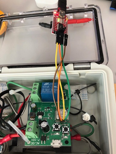
 ukd4ve
on 20 Dec 2020
ukd4ve
on 20 Dec 2020
Related issues
 kckepz
·
3Comments
kckepz
·
3Comments
 renne
·
3Comments
renne
·
3Comments
 grizewald
·
3Comments
grizewald
·
3Comments
 JoergZ2
·
3Comments
JoergZ2
·
3Comments
 abzman
·
3Comments
abzman
·
3Comments
Most helpful comment
Hello,
i am new to this forum and programming in general but following this tutorial i managed to flash my 1 ch sonoff and it is working. I know how it is hard sometimes to find information about all stepsHere is instruction how i did it.
I hope this will be helpful.
Update: after flashing to tasmota, 1CH relay started to swich on/off randomly. This happens all the time then relay looses wifi connection and restores it. I could not find any reliable solution for this problem.
Only solution i found and it is working 100% time is switch to ESPURNA 1ch relay firmware. Now i'm testing ESPURNA for few days and absolutely happy with results.