Prusaslicer: Superfluous gap fill when trying to achieve integer number of perimeters
Version
1.41.1+win64
Operating system type + version
Windows 10 Pro 64bit
Behavior
Trying to achieve an integer number of perimeters in walls is not feasible without tinkering with extrusion width.
What is setup:
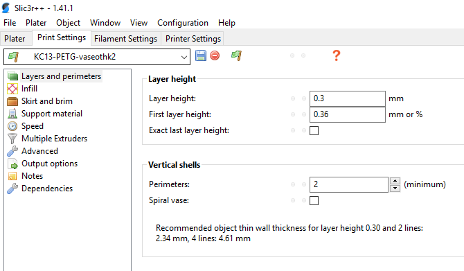
- Extrusion width (all) : 0.5mm
- Optional: Detect thin walls disabled
- Optional: Infill/perimeter overlap: 0
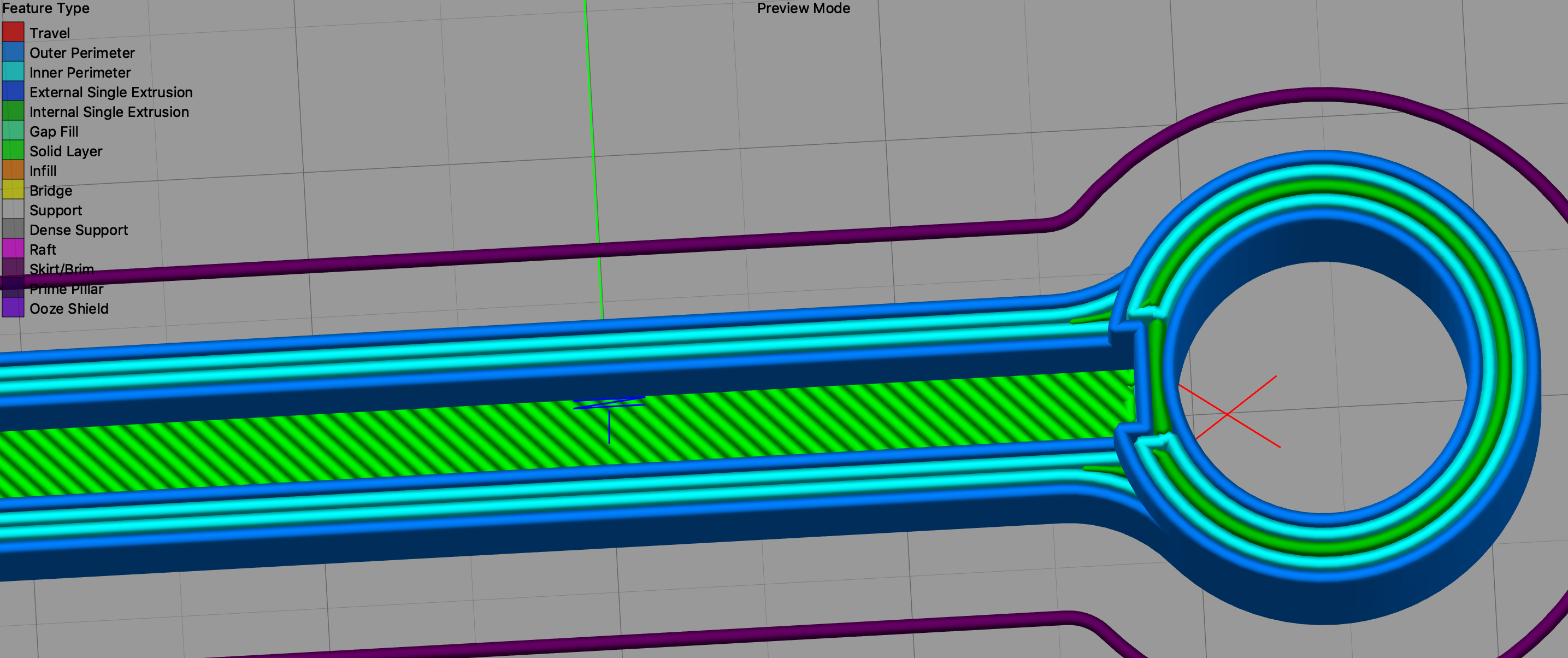
Geometry has exactly 2mm wall thickness. One would expect the slicer to produce exactly 4 perimeters and reach the required wall thickness. However, a gap fill is added.

__Note__: enabling or disabling "Detect thin walls" doesn't change anything. Changing or disabling the infill/perimeter overlap doesn't change anything.
STL/Config (.ZIP) where problem occurs
 beeb
beeb
All 23 comments
Your expectation is wrong because you don't account for overlaps of the perimeter lines. The extrusion cross section is assumed to be oval (as it always is), so the neighboring line is laid a bit closer than the extrusion width, which results in the gap in the middle. Setting perimeter width to 0.52 produces no gap fill.
What exactly is the problem with this behaviour? Did the gap fill negatively influence the result in some way?
 lukasmatena
on 14 Nov 2018
lukasmatena
on 14 Nov 2018
Yes the gap fill is negative in the sense that it adds printing time, which I want to optimize as much as possible. How did you come to the additional 0.02mm to add to the extrusion width? Is there a formula that we can use to figure out what the extrusion width should be relative to the wall thickness to produce the desired result? How is the overlap between adjascent perimeters controlled?
beeb
on 14 Nov 2018
I think in the end it comes down to how extrusion width is defined. In my mind, extrusion width is equal to the distance between two adjascent perimeters (assuming they have the same extrusion width). If Slic3r has a different definition of it, then how can we control the spacing between two adjascent perimeters to produce the desired result (integer number of perimeters inside a wall)?
beeb
on 14 Nov 2018
I came to it by what I would call an educated guess. But yes, there is a formula and it is actually quite easy to derive. I suggest you look at https://manual.slic3r.org/advanced/flow-math from the upstream Slic3r manual. You'll find both the formula and the reasoning behind it.
lukasmatena
on 14 Nov 2018
Thanks for the resource! I found what I was looking for :
spacing = extrusion_width - layer_height * (1 - PI/4)
So for 0.5mm extrusion width and 0.2mm layer height, the spacing is 0.457079633.
Inversely, the required extrusion width for a 0.5mm spacing is 0.542920367mm...
Isn't it a bit complicated to figure out on a daily basis? I would much rather control the spacing than the actual extrusion width before overlap. Especially since the overlap changes depending on the layer height.
beeb
on 14 Nov 2018
At the moment every slicer is using the extrusion width and not the spacing, so this is the value we (the users) are used to. And as the extrusion width is somewhat dependent on the nozzle diameter used, it makes sense to enter this value and not a width between lines. This value was never of interest in any of my designs at least.
 Sebastianv650
on 14 Nov 2018
Sebastianv650
on 14 Nov 2018
At the moment every slicer is using the extrusion width and not the spacing
@Sebastianv650 The other slicer I use on a daily basis (S3D) uses spacing as you can see below (same part, same settings - extrusion width 0.5mm, layer height 0.2mm). There is no gap fill in the thin walls with 4 perimeters. It's much more convenient to use when designing parts with thin walls and when optimizing printing time is important.
This value was never of interest in any of my designs at least
A lot of designers use a round number of millimeters for dimensions, so it often makes sense to use a 0.5mm spacing in order to speed up the print and be left with minimal gap fill and/or infill.
beeb
on 14 Nov 2018
I really like the "helper text" that has been included in some versions of Slic3r and Slic3rPE. I see it in supermerill's recent beta releases of Slic3rPE:
The issue still remains though.. If I want a very specific thickness thin-wall part, I have to change all my extrusion widths... I wish there was a way to switch between methods so we could "make perimeters fit" into our 2mm-thick objects without having to do any math or guessing.
 hunterfrerich
on 14 Nov 2018
hunterfrerich
on 14 Nov 2018
That's very nicely put @hunterfrerich ! Basically what I thought was a bug is rather now a feature request.
It would be nice to have a checkbox to switch between:
- calculating the spacing from the given extrusion width + layer height (current mechanism)
- calculating extrusion width from given spacing + layer height (desired new option)
I am not sure of all the implications, but a starting point is simply to turn around the equation from above to give:
extrusion_width = spacing + layer_height * (1 - PI/4)
beeb
on 14 Nov 2018
@FidelCapo would you please confirm this?
On Wed, Nov 14, 2018 at 4:01 PM Valentin Bersier notifications@github.com
wrote:
Version
1.41.1+win64
Operating system type + versionWindows 10 Pro 64bit
BehaviorTrying to achieve an integer number of perimeters in walls is not feasible
without tinkering with extrusion width.What is setup:
- Extrusion width (all) : 0.5mm
- Optional: Detect thin walls disabled
- Optional: Infill/perimeter overlap: 0
Geometry has exactly 2mm wall thickness. One would expect the slicer to
produce exactly 4 perimeters and reach the required wall thickness.
However, a gap fill is added.[image: capture]
https://user-images.githubusercontent.com/703631/48490644-26abe180-e826-11e8-9858-e7e8d442df7a.PNG
STL/Config (.ZIP) where problem occursEnclosure.zip
https://github.com/prusa3d/Slic3r/files/2581222/Enclosure.zip—
You are receiving this because you are subscribed to this thread.
Reply to this email directly, view it on GitHub
https://github.com/prusa3d/Slic3r/issues/1405, or mute the thread
https://github.com/notifications/unsubscribe-auth/AFj5Izd18w8PxWBz3mlAyTwyKevjQQQnks5uvDAygaJpZM4Yd64s
.
 bubnikv
on 15 Nov 2018
bubnikv
on 15 Nov 2018
calculating the spacing from the given extrusion width + layer height (current mechanism)
calculating extrusion width from given spacing + layer height (desired new option)
So how would you let Slic3r switch between the two approaches? Automatically? That would be quite confusing I suppose.
bubnikv
on 15 Nov 2018
You can already use the "helper text" to adjust your extrusion width to fit your expected object wall thickness.
bubnikv
on 15 Nov 2018
@bubnikv I was proposing a checkbox style UI element but this is probably not my decision to make. Regarding the helper text, it would make more sense to have it in the extrusion width (advanced) tab in that case. Otherwise when you adjust your extrusion width, you need to switch tabs to read the helper text, then go back to advanced to tune again the value etc.
beeb
on 15 Nov 2018
I really like the "helper text" that has been included in some versions of Slic3r and Slic3rPE. I see it in supermerill's recent beta releases of Slic3rPE:
I didn't do anything for that, it's all to the credit of the prusa team.
For the issue, it's a bit complicated. The width of external & internal perimeter are different, so are their spacing and the spacing between them.
@bubnikv: I assumed that when the perimeters overlap a bit (perimeterGenerator:l104), the flow is reduced to take that into account, but with further investigation, it seems it's not doing anything special and so may overextrude. Do you confirm that?
 supermerill
on 21 Nov 2018
supermerill
on 21 Nov 2018
Yes, if the perimeters overlap, there is over extrusion.
On Wed, Nov 21, 2018 at 12:08 PM Merill notifications@github.com wrote:
I really like the "helper text" that has been included in some versions of
Slic3r and Slic3rPE. I see it in supermerill's
https://github.com/supermerill/Slic3r/releases recent beta releases of
Slic3rPE:I didn't do anything for that, it's all to the credit of the prusa team.
For the issue, it's a bit complicated. The width of external & internal
perimeter are different, so are their spacing and the spacing between them.@bubnikv https://github.com/bubnikv: I assumed that when the perimeters
overlap a bit (perimeterGenerator:l104), the flow is reduced to take that
into account, but with further investigation, it seems it's not doing
anything special and so may overextrude. Do you confirm that?—
You are receiving this because you were mentioned.
Reply to this email directly, view it on GitHub
https://github.com/prusa3d/Slic3r/issues/1405#issuecomment-440625666,
or mute the thread
https://github.com/notifications/unsubscribe-auth/AFj5Iy3CgmLXqICOKg99Qs6oNomjZPV0ks5uxTQvgaJpZM4Yd64s
.
bubnikv
on 21 Nov 2018
if the perimeters overlap, there is over extrusion
I don't think there is, since the perimeters don't have a rectangular cross-section. See the link that @lukasmatena posted above. The perimeters overlap to compensate for the empty space shown in yellow below.

beeb
on 21 Nov 2018
Well, we may add the same helper test to the extrusion width box, that makes sense, if you plan to tinker with the extrusion width. But frankly, I would refrain from touching the extrusion width to achieve the integer number of extrusions, I would rather change the model.
Anyway, I see a usefulness of the hint at the extrusion width box.
bubnikv
on 13 Dec 2018
Okay that's already something, I could work with that. Regarding your comment on changing the model, that's not always possible or convenient without the source CAD file, which was the main motivator for me (and a lot of people) to change the extrusion width.
beeb
on 13 Dec 2018
That's why I set my external parameters to w + 0.5 * h * (1-pi /4) and internal ones to w + h * (1-pi /4). Where w is the desired width, I usually set that to my nozzle, and h is the layer height.
But it's not perfect, the formula breaks down for a single line, where the perimeter width would need to be just w.
Furhtermore, its awkward, because it depends on the layer height. I'm defining my own "vendor" configuration with inheritance, which makes it easier to deal with, but it's still not very user friendly.
Finally, I don't think it handles the variable layer height feature at all. And if you add modifiers to change the layer height for parts of the model, you need to change the widths as well.
@bubnikv, I repeat what was said above, changing the model is often not an option. Even if you have the cad file, depending on how parameteric it is, it could take considerable effort.
Furthermore, even when designing the model, you have to use different widths, depending on how many wall lines you want to have for that feature. So you either have to enter one of the magic numbers that Slic3r gives you, or define a rather complex formula for calculating it so you can enter the number of lines you want as a parameter instead. However as far as I know, conditional formulas are not supported in Fusion 360 for example, so you would have to use a script for it.
I don't see your concerns about changing the extrusion width from an user point of view. The range of acceptable extrusion withs for a given nozzle is quite large. You can see various mantras repeated all over places, like always use 1.25 (or 1.2x, and even 1.5x) times the nozzle, Slic3rPE uses 1.125x, the manual says the thinnest acceptable one is 1.05x, the maximum mentioned in the manual is 1.7x . Cura for some strange reason even use a width smaller than the nozzle size. I have tried to find some scientific sources for these, but none seem to exist. So I believe as long as you stay within the acceptable range, whatever that is, you should be ok.
I understand your concerns, from a coing point of view, since it's probably not as simple as calculating the new value right after loading the configuration, especially if you take adaptive layer heights into account and also special cases like bridging.
In the future I would even like to see a movement towards variable extrusion widths. I believe now with various implementations of linear advance, this should be feasible. In addition to making walls the perfect width, it could also eliminate gap fill in many other places too. It would also be possible to make really nice looking concentric infills. Also if we allow the width to go smaller than the nozzle width if really needed, it could allow for more pointy and detailed features where needed. The implementation side would definitely not be easy, but I see huge potentials there.
 fredizzimo
on 2 Jan 2019
fredizzimo
on 2 Jan 2019
In the future I would even like to see a movement towards variable extrusion widths.
That is certainly in the back of my head since I started with FDM. One should start with a support of trapezoidal segments in the firmware first though.
bubnikv
on 2 Jan 2019
I don't think trapezodial segements would be strictly needed, although the result would probably be better that way.
The slicer could generate sufficiently short segments of varying widths. Since it's physically impossible to change the flow rate in an instant, there would be automatically be a smooth transition between the segments. However, it would probably fail to generate the same kind of transition for adjacent lines, especially if ther widths are different. So you would get either a small underextrusion or overextrusion at those points. I'm not sure how bad that would be, so it's possible that you are right.
It would be quite easy to test it out with a firmware supporting linear advance, and constructing the gcode manually, or making a small script to test it out. I might do that at some point with Klipper.
fredizzimo
on 2 Jan 2019
Too many very short segments easily overload the 8bit arduino based
firmwares, so your printer will start to stutter.
On Wed, Jan 2, 2019 at 2:20 PM fredizzimo notifications@github.com wrote:
I don't think trapezodial segements would be strictly needed, although the
result would probably be better that way.The slicer could generate sufficiently short segments of varying widths.
Since it's physically impossible to change the flow rate in an instant,
there would be automatically be a smooth transition between the segments.
However, it would probably fail to generate the same kind of transition for
adjacent lines, especially if ther widths are different. So you would get
either a small underextrusion or overextrusion at those points. I'm not
sure how bad that would be, so it's possible that you are right.It would be quite easy to test it out with a firmware supporting linear
advance, and constructing the gcode manually, or making a small script to
test it out. I might do that at some point with Klipper.—
You are receiving this because you were mentioned.
Reply to this email directly, view it on GitHub
https://github.com/prusa3d/Slic3r/issues/1405#issuecomment-450861511,
or mute the thread
https://github.com/notifications/unsubscribe-auth/AFj5I5HxKzWc19QMK9doYW8_Fjl49Z1Bks5u_LIygaJpZM4Yd64s
.
bubnikv
on 2 Jan 2019
This is what I use based upon https://manual.slic3r.org/advanced/flow-math:
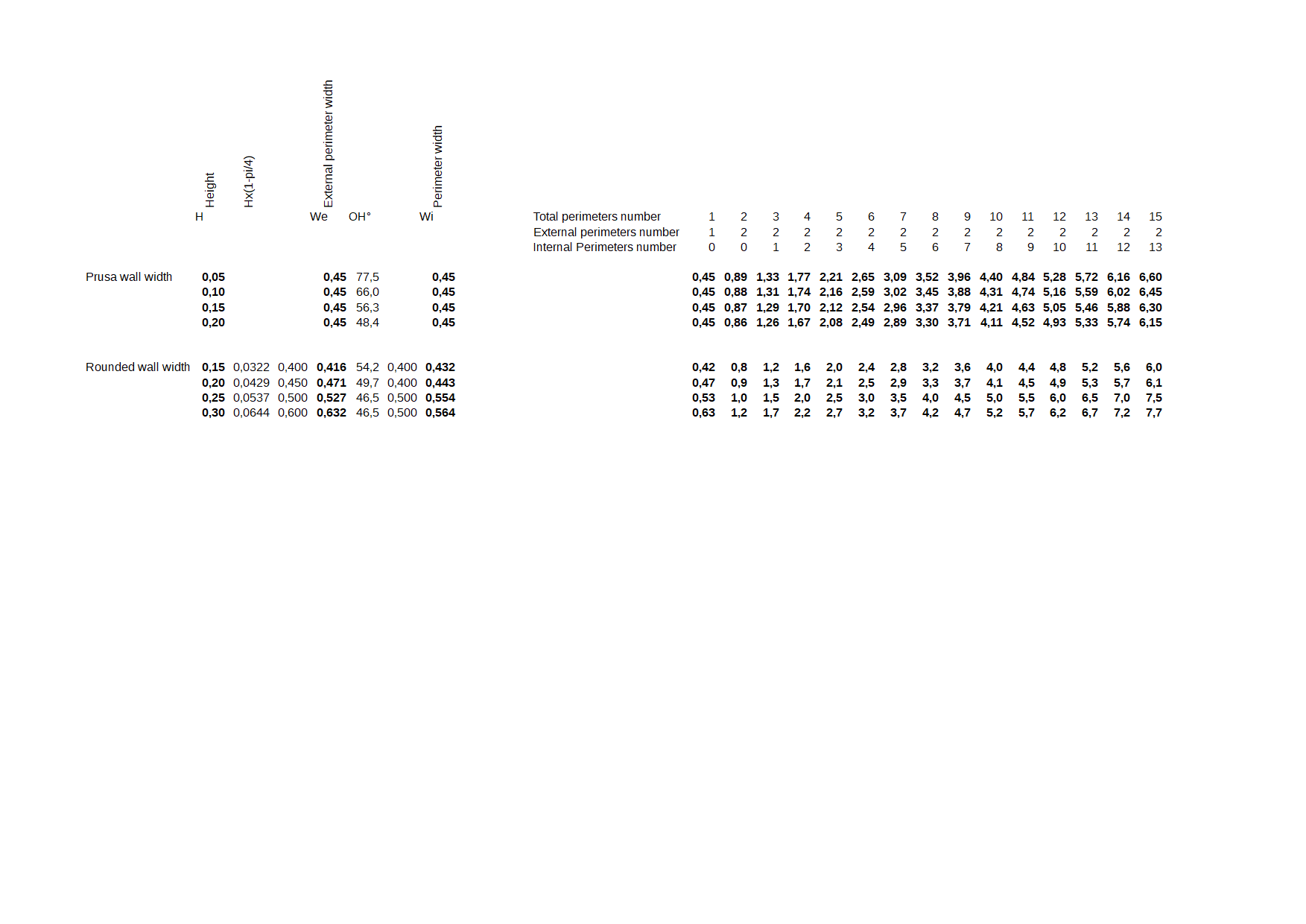
If I want quite rounded wall width, I design my parts with those values in mind (second part of the table). Can be not exact due to some internal calculation.
 rongith
on 11 Jan 2019
rongith
on 11 Jan 2019
Related issues
 domesticatedviking
·
43Comments
domesticatedviking
·
43Comments
 nicksears
·
38Comments
nicksears
·
38Comments
 ruedli
·
31Comments
ruedli
·
31Comments
 RosieTheRabbit
·
60Comments
RosieTheRabbit
·
60Comments
 carlvonkessler
·
42Comments
carlvonkessler
·
42Comments
Most helpful comment
Thanks for the resource! I found what I was looking for :
spacing = extrusion_width - layer_height * (1 - PI/4)So for 0.5mm extrusion width and 0.2mm layer height, the spacing is 0.457079633.
Inversely, the required extrusion width for a 0.5mm spacing is 0.542920367mm...
Isn't it a bit complicated to figure out on a daily basis? I would much rather control the spacing than the actual extrusion width before overlap. Especially since the overlap changes depending on the layer height.