I'm back in the conceptual phase. This is how I understand the Amiga screen geometry at the moment:

The numbers in square brackets (intervals) refer to the DMA cycle number (horizontally) and the vpos value, respectively.
Before I can continue to implement, I need to clarify the following:
- Is it true that the HSYNC does not start at DMA cycle 0? If my image is correct, then graphics data that is produced during the first few DMA cycles (e.g., by the sprite sequencer) still belongs to the previous line.
The graphics also contains a design proposal for the displaying events. If a line belongs to the display window (as specified by register DIWSTRT and DIWSTOP), I plan to schedule the following events:
- HBLANK: Fills the rest of the previous line with the background color
- DIWSTRT: Fills the beginning of the line with the background color
- DRAW: Draws a chunk of 16 pixels in hires mode or 32 pixels in lores mode (will be scheduled every fourth DMA cycle in hires mode and every eights DMA cycle in lores mode).
- DIWSTOP: basically the same as DRAW
- HSYNC: Triggers the CIA counter, checks for VSYNC etc.
Please let my know if this makes sense to you or if it doesn't? 🤔
 dirkwhoffmann
All 13 comments
Hi Dirk,
picture looks good for me, but I can't really answer your HSYNC DMA cycle question. And I am afraid this issue here on GitHub does not get the amount of attention which it really deserves 😀.
When I have a look the EnglishAmigaBoard (EAB) forum then I find tons of questions like yours. But not exactly the HSYNC DMA cycle 0 question.
Toni Wilen the guy who did the WinUAE looks regularly into the EAB forums and gives hints to others. (I bet he has the deepest and widest knowledge about technical Amiga stuff)
for example like this here
http://eab.abime.net/showthread.php?t=72575
Maybe it would be wise to place your question there too? I think it is the biggest active audience with knowledge about technical AmigaStuff on the net. @h5n1xp also has his thread relating to his omega development there and he did post some questions there too, which had been also answered by Toni. (you already know the link http://eab.abime.net/showthread.php?t=90316&page=9)
Did you already thought about opening a new thread for difficult questions like this and questions which will definitely be coming on English Amiga Board > Coders > Coders. Asm / Hardware?
I did really enjoy the journey of your development so far. I would be very happy when you get the information which you need to be able to continue.😃
EDIT:
English Amiga Board > Coders > Coders. Asm / Hardware > Undocumented Amiga hardware stuff
this thread is also appropriate for the question I think.
 mithrendal
on 23 Mar 2019
mithrendal
on 23 Mar 2019
"And I am afraid this issue here on GitHub does not get the amount of attention which it really deserves"
You made a point here 😂. This GitHub repo is really not the the most crowded place on earth yet.
"Toni Wilen the guy who did the WinUAE ..."
Oh yes, Toni's name is really everywhere. I've already used a couple of his hints which I found via Google.
dirkwhoffmann
on 23 Mar 2019
This is the really interesting part!
I think for the purposes of the display, it starts at 0, as that is the first even DMA cycle.
Now you are crossing into something I had a lot of problems with when getting my first display from Omega.
This page in the HRM (second paragraph) is what really confused me:
http://amigadev.elowar.com/read/ADCD_2.1/Hardware_Manual_guide/node0072.html
The Amiga can “smooth scroll” horizontally 1pixel at a time, but it can only fetch (i.e. draw) 16pixels at a time. From the page above I understood that to mean, the DMA fetches the data, but is only put on the screen where the display window starts. So as long as you have fetched 16pixels worth of data you can display them via the display window anywhere up to 16pixels to the right. Now I might have this totally wrong (and not for the first time 😂)... but the display generation seems complex.
When I get time, I will write a set of programs to run on my Amiga to test my hypothesis.
 h5n1xp
on 23 Mar 2019
h5n1xp
on 23 Mar 2019
The page in the HRM is really cryptic and I agree that writing small test programs is the way to go.
I think the main experiment is the following: If we narrow the viewable area by adjusting DIWSTRT and DIWSTOP and keep the DMA setting as it is, do we get the picture in the middle or do we get the picture to the right:
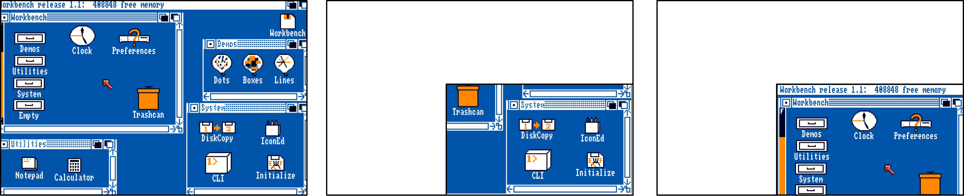
If I was to hardware designer, my chip would produce the picture in the middle.
dirkwhoffmann
on 24 Mar 2019
I’ll try and get an hour tonight and write some test code to see what sort of output we are expecting (hopefully we’ll se something like your guide images). That should inform how to move forward.
This should help vAmiga, as I’m still debating if I want to make Omega’s display more accurate... it’s not part of my original specification (my focus is still on OS legal applications)... and hopefully soon push on with the RaspberryPi side of the emulation.
h5n1xp
on 24 Mar 2019
The real world size of a 3.5 floppy disk has a width of 9cm and a height of 9,4 cm. I don't know whether the amiga engineers did think of proper proportions when coding the disk and hand image, but on vAmigas hand and disk boot image the disk has a width of 9cm but "only" a height of 7cm. The scaling factor for the width may be too big?
EDIT: just corrected the numbers, it is 9cm width by 9.4cm height.
mithrendal
on 24 Mar 2019
I was searching for workbench disk hand images on the original commodore 1081 monitor
I found so far two (on ebay ) with the disk size in pixel
width= 134, height=100 => ratio 1.34
width=154, height =112 => ratio 1.37
original disk size in cm is
width=9, height=9.4 => ratio 0.957
vAmigas disk ratio in pixel is
width=246, height=182 => ratio 1.35
vAmigas disk ratio in cm (taken from the screen) is
width=9, height=7 => ratio 1.28
That means to me that commodore did some mistake in coding the correct size of the disk image.
vAmigas proportions seems to be correct.
mithrendal
on 24 Mar 2019
The page in the HRM is really cryptic and I agree that writing small test programs is the way to go.
I think the main experiment is the following: If we narrow the viewable area by adjusting DIWSTRT and DIWSTOP and keep the DMA setting as it is, do we get the picture in the middle or do we get the picture to the right:
If I was to hardware designer, my chip would produce the picture in the middle.
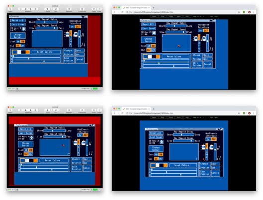
Ok, so after some experiments with a real A500. Here is how diwstrt behaves:
The vpos, is the line where the fetch will start, so the vpos behaves like picture 3.
The hpos behaves like picture 2.
Both have 1 pixel (lores) resolution.
Increasing the ddfstrt just corrupts the display, as the fetch wraps too soon. Altering ddfstrt and ddfstop equally causes the screen to jump 16 pixels in the direction of the adjustment.
This is weird, because when I open the debugger in UAE, I see that the vpos in diwstrt is often set to (seemingly) random values, rather than the 0x2C which one would expect... I can only guess the vpos Fetch start is controlled by the copper list starting the bitplane DMA at the correct time.
h5n1xp
on 25 Mar 2019
Wow, thanks a lot! That helps and makes perfectly sense to me.
I should have known about the vpos behaviour. I remember to have read somewhere that the VSYNC area can be enlarged by modifying DIWSTRT.
I expected hpos to behave like picture 2, because DMA must start a few cycles before the display window opens. This means that DMA and DIW must be decoupled hardware wise. To achieve picture 3, the chip would have to store already fetched DMA data somewhere which is expensive.
The display corruption also makes sense. The number of performed DMA cycles must match the bitplane size divided by 16. If you increased ddfstrt and used a bitplane modulo value of -1 (if negative values are possible), the corruption should go away. Alternatively, decreasing ddfstrt und increasing the modulo should also remove the corruption.
"This is weird, because when I open the debugger in UAE, I see that the vpos in diwstrt is often set to (seemingly) random values"
I bet that the (random) value is less or equal 25. Such values cannot make any harm because the VBLANK area spans from 0 .. 25. Hence, the first visible line is MAX(25, DIWSTRT::V)
Again, thanks a lot for this great work!
BTW, how did you write the test program? Aztec C and Emacs on the Amiga like in the old days? 🤤
dirkwhoffmann
on 25 Mar 2019
Wow, thanks a lot! That helps and makes perfectly sense to me.
I should have known about the vpos behaviour. I remember to have read somewhere that the VSYNC area can be enlarged by modifying DIWSTRT.
Yes, if you look at Omega's DMA sequencer, it doesn't start fetching until the vpos has reached the diwstrt vpos. This is the one thing I was fairly certain on... until I started getting values less than 44... and my display was all messed up. So I just put a hard stop of no fetches until line 44 reached, then it looks at the diwstrt. This allows the screen dragging in the OS.
I expected hpos to behave like picture 2, because DMA must start a few cycles before the display window opens. This means that DMA and DIW must be decoupled hardware wise. To achieve picture 3, the chip would have to store already fetched DMA data somewhere which is expensive.
Indeed, but I'm struggling to see the value of the diwstrt hpos. surely ddfstrt fills the hpos-start role just fine? Omega currently uses the ddfstrt as the hpos start, and ignores diwstrt hpos.
The display corruption also makes sense. The number of performed DMA cycles must match the bitplane size divided by 16. If you increased ddfstrt _and_ used a bitplane modulo value of -1 (if negative values are possible), the corruption should go away. Alternatively, decreasing ddfstrt und increasing the modulo should also remove the corruption.
The ddfstop values are a bit of a minefield too. Again in Omega, I currently ignore them and calculate the ddfstop based on the ddfstrt + bitmapWidth. Actually using the the ddfstop values causes the display corruption in workbench. Remember, workbench is my ultimate goal, so I have prioritised that over games. Though I am desperately trying to figure out what I've done wrong with the blitter to cause the corruption in Defender of the Crown.
"This is weird, because when I open the debugger in UAE, I see that the vpos in diwstrt is often set to (seemingly) random values"
I bet that the (random) value is less or equal 25. Such values cannot make any harm because the VBLANK area spans from 0 .. 25. Hence, the first visible line is MAX(25, DIWSTRT::V)
Sometimes 0, sometimes 5, sometimes 44... the debugger in WinUAE is a real pain to use... hence why I still have my A500 with an ARIII cart set up... but ARIII is also a bit crap.
Again, thanks a lot for this great work!
BTW, how did you write the test program? Aztec C and Emacs on the Amiga like in the old days?
My A1200 (with SAS/C 6) is packed away, since we were supposed to be moving house (but this is not going well), so the only real Amiga I have is my A500 under the TV in the living room.
I couldn't find my Devpac disks, but I did find BlitzBasic 2.1! So It was easy just to poke the registers to see what happens. I'll also be using it to write some blitter test programs... Now this would be easier if I could find my old WinUAE configs :smile:
h5n1xp
on 25 Mar 2019
Photon on EAB explains:
The easiest way to understand it is to go from the standard values and modify them. DDFSTRT=$38 -> DIWSTRT $81. For each 16px you add/subtract from DIWSTRT, add/subtract 8 from DDFSTRT. That ensures that your copperlist will work 100% in all modes on all machines.
DIW is just the clipping rectangle for the actually by DMA fetched bitplane-data from memory. It can be larger or smaller than the DDF DMA start/stop.
h5n1xp
on 25 Mar 2019
Thanks for the EAB link, it helps a lot! Basically, the Amiga seems to use a similar approach than the C64. There are two border flipflop (or latches). One of them controls the vertical border and the other one the horizontal border. There are comparator circuits that match DIWSTRT/DIWSTOP with the current beam position and switch the flipflops on and off. DMA is completely independent with the exception that DMA can only happen in those rasterlines with the vertical frame flipflop switched on.
dirkwhoffmann
on 26 Mar 2019
I think I'm on the right track now. The new code seems to handle the DIW values correctly, as well as the horizontal scrolling values. Left: vAmiga (red colors = debug colours, think of it as being blue). Right: SAE 0.9.
dirkwhoffmann
on 30 May 2019
Related issues
dirkwhoffmann
·
3Comments
dirkwhoffmann
·
3Comments
dirkwhoffmann
·
3Comments
dirkwhoffmann
·
4Comments
 Alessandro1970
·
4Comments
Alessandro1970
·
4Comments
Most helpful comment
Ok, so after some experiments with a real A500. Here is how diwstrt behaves:
The vpos, is the line where the fetch will start, so the vpos behaves like picture 3.
The hpos behaves like picture 2.
Both have 1 pixel (lores) resolution.
Increasing the ddfstrt just corrupts the display, as the fetch wraps too soon. Altering ddfstrt and ddfstop equally causes the screen to jump 16 pixels in the direction of the adjustment.
This is weird, because when I open the debugger in UAE, I see that the vpos in diwstrt is often set to (seemingly) random values, rather than the 0x2C which one would expect... I can only guess the vpos Fetch start is controlled by the copper list starting the bitplane DMA at the correct time.