Tasmota: MagicHome LED (ESP-IR-B-v2.3 / ESP8285MOD ESP-M2) not working with tasmota f/w
Hi I bought 2 of these devices cheap as chips off ebay. V2.3 with no RX/TX pads and no IR connected.
I flashed one of them with the latest tasmota build using esptool (via raspi with serialUSB), making backup, erasing flash and uploading the sonoff.bin with no problems. After completing the flash, powered off and disconnected (GND last as per wiki) and powered up again but initially saw no AP listening for initial setup. Tried a few more times and eventually noticed an AP called ESP-
What is the expected behaviour? These things have no button, so should the start in AP mode everytime until configured? Do I have to do something to trigger the AP mode? Do I have to do something special to connect to it?
The second device I tried flashing with a slightly older tasmota f/w that I had used on my sonoff basic with success, but on the magichome, the same flaky behaviour as the first. Suspecting dodgy hardware, I flashed the second device back to it's stock firmware, downloaded the magichome app and used that to set it up. The device worked as expected again, magichome app found it as an AP, and connected it to my home wifi without issues, (other than I don't want to use magichome f/w!!)
So is this new unsupported hardware? did I do something wrong in setup?
Is there a way to debug this? I tried pointing putty at the serial port connected to the device using 9600 and 115200, but both only showed garbage.

 oxcxsxixbxaxn
All 80 comments
Hi,
i have the same modul (it looks exactly as yours)
My first flash was not successful. I didnt connect to my Wlan.
After resolder the connections (i was sure it works...) the second attempt works as it should.
I have all my settings in user_config.h. No need to do anything on the module after power up.
https://github.com/arendst/Sonoff-Tasmota/wiki/Beginner-Guide---Create-your-own-Firmware-Build#building-the-firmware
Just a look in the router, what ip it has, launch browser and config the modul -> Ready and working
Hint: setOption15 1
 Jason2866
on 11 Feb 2018
Jason2866
on 11 Feb 2018
Hi,
When you say you first flash was not successful, you mean the flash operation itself? or the behaviour after a seemingly successful flash?
Thinking about it, one thing I did different is I forgot to disconnect the gpio-0 from GND through out the backup, erase and flash, only disconnecting it after "successful" flash completed and I disconnected everything... would this make a difference?
This is how the flash output looked, seems fine??
# esptool.py -p /dev/ttyUSB0 -b 115200 write_flash -fs 1MB -fm dout 0x0 sonoff.bin
esptool.py v2.3-dev
Connecting....
Detecting chip type... ESP8266
Chip is ESP8285
Uploading stub...
Running stub...
Stub running...
Configuring flash size...
Compressed 495808 bytes to 341889...
Wrote 495808 bytes (341889 compressed) at 0x00000000 in 31.8 seconds (effective 124.8 kbit/s)...
Hash of data verified.
Leaving...
Hard resetting...
Flash not successfull in my case ment everything looks good like your flash.
But after power it up it doesnt work. Second attempt was working.
The only difference between 1st and 2nd flash. At try 2 i did a erase with esptool.
After erase disconnect and reconnect. This is neccersary!
Jason2866
on 11 Feb 2018
I erased each time, only difference was leaving the gpio-0 connected to GND
so...
connected GND, tx, rx, gpio-0 to GND and powered up,
Backed up with esptool and disconnected power, waited a few seconds
Reconnected power and Erased flash then disconnected power
Reconnected power and flashed f/w, when complete removed power, removed tx/rx/gpio-0 then GND
I'll try again with custom firmware with my wifi setting already set and see if that gets me further
Thanks
oxcxsxixbxaxn
on 11 Feb 2018
same model, arrived a few days ago from aliexpress.
it mounts the ESP-M2, a module with ESP8285
here the link for reference: https://it.aliexpress.com/item/Magic-Home-Mini-RGB-RGBW-Wifi-Controller-For-Led-Strip-Panel-light-Timing-Function-16million-colors/32686853650.html?spm=a2g0s.9042311.0.0.O5enRa
by the way, the label on the case was put upside down so the +VCC pin on led connector is reported in the opposite side
before starting to solder & wire it, I tested with myhome app and I have seen all the colors...
it is the model without IR receiver but with also W pin, even if I don't have an RGBW strip.
the cost was quite the same..
I glued a connector to be able to make experiments without wiring problems
be careful with wire soldering, it is a tough small space


I didn't have any problem in flashing and tasmoting it
I made these configurations:
19:50:38 MQT: letto4/magicHome/INFO1 = {"Module":"MagicHome","Version":"5.10.0g","FallbackTopic":"DVES_96A3DE","GroupTopic":"sonoffs"}
19:50:38 MQT: letto4/magicHome/INFO2 = {"WebServerMode":"Admin","Hostname":"magicHome-0990","IPAddress":"192.168.10.205"}
19:50:38 MQT: letto4/magicHome/INFO3 = {"RestartReason":"Software/System restart"}
19:50:39 MQT: letto4/magicHome/RESULT = {"POWER":"OFF"}
19:50:39 MQT: letto4/magicHome/POWER = OFF
19:52:29 CMD: setoption15
19:52:29 MQT: letto4/magicHome/RESULT = {"SetOption15":"ON"}
19:52:32 CMD: color 1
19:52:32 MQT: letto4/magicHome/RESULT = {"POWER":"ON","Dimmer":100,"Color":"FF0000"}
19:52:35 CMD: color 2
19:52:35 MQT: letto4/magicHome/RESULT = {"POWER":"ON","Dimmer":100,"Color":"00FF00"}
19:52:37 CMD: color 3
19:52:37 MQT: letto4/magicHome/RESULT = {"POWER":"ON","Dimmer":100,"Color":"0000FF"}
but after boot and configuration, there is only the RED light switched on
it seems the other two colors are dead
I tried also to map where mosfets are mapped on GPIO on my board, to check on ESP pinout if it is a hardware/driver problem or a pin configuration problem, even if I don't have now an oscilloscope in my hands
Jason2866 and oxcxsxixbxaxn, are you able to drive all the 3 colors?
any suggestion?
maybe I forgot to configure any parameter?
can anybody suggest me the pinout from ESP for RGBW in magichome standard configuration?
 app41
on 11 Feb 2018
app41
on 11 Feb 2018
Hi app41,
i see no error. It should work. I will connect mine. At the moment it is not in use.
Just put it together for fun and testing...
Jason2866
on 11 Feb 2018
I have still to flash tasmota, but when I plugged my rgbw strip into device running magichome firmware, all 3 colours and WW lit correctly. Funnily enough I only checked the V+ was in the correct side and didn't look at the order printed on the strip... that actually shows +GRBW...

oxcxsxixbxaxn
on 11 Feb 2018
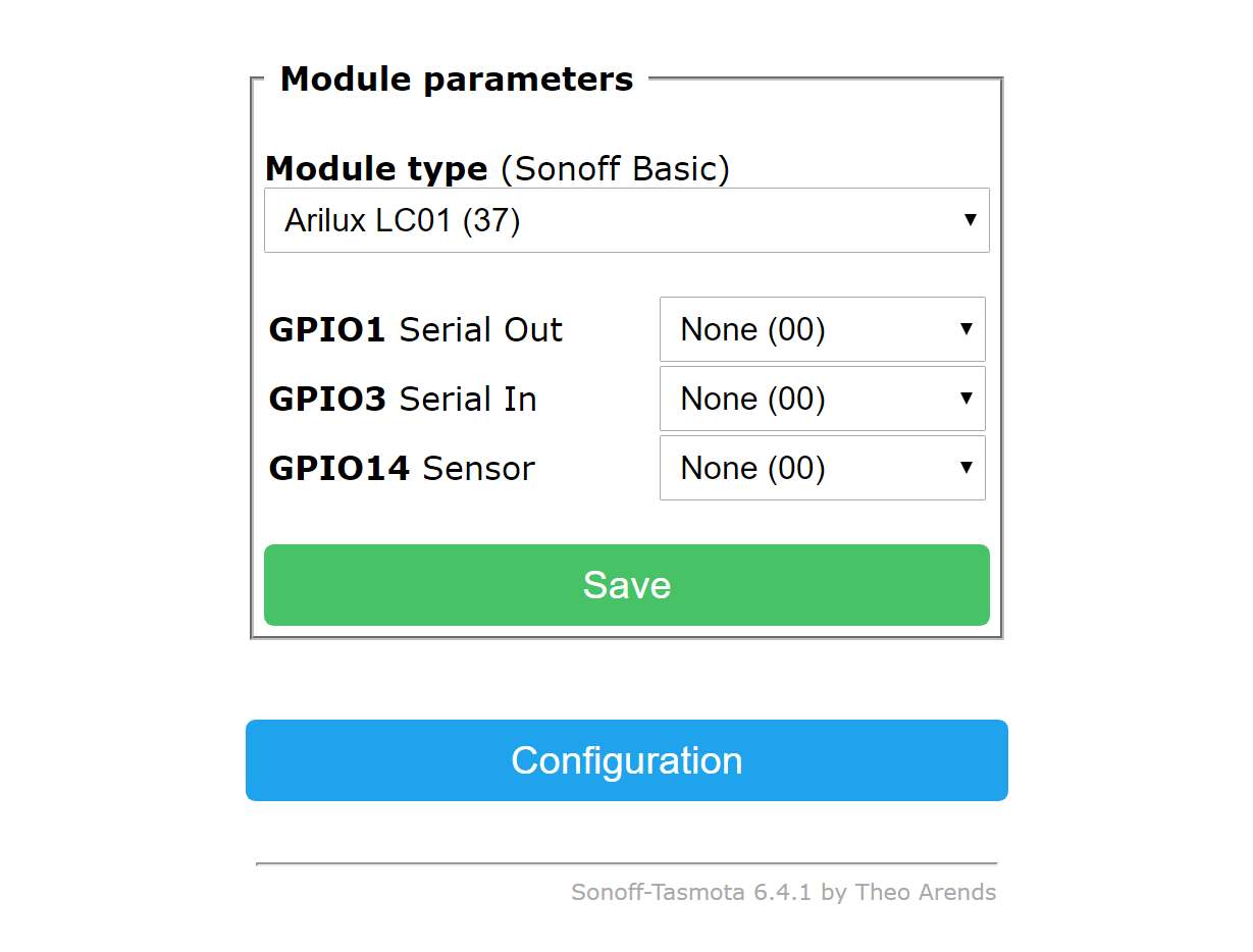
This is my setup with correct colors (Modul 37, SetOption15 1 and nothing else)
00:00:00 Project sonoff LED (Topic sonoff-959C17, Fallback sonoff-959C17, GroupTopic sonoffs) Version 5.11.1a
00:00:00 WIF: Connecting to AP1 Jason_Home_WLAN in mode 11N as sonoff-959C17-7191...
00:00:04 WIF: Connected
00:00:04 DNS: Initialized
00:00:04 HTP: Web server active on sonoff-959C17-7191.local with IP address 192.168.2.135
00:00:04 UPP: Multicast (re)joined
00:00:05 UPP: Multicast (re)joined
20:43:59 MQT: Attempting connection...
20:43:59 MQT: Connected
20:43:59 MQT: tele/sonoff-959C17/LWT = Online (retained)
20:43:59 MQT: cmnd/sonoff-959C17/POWER =
20:43:59 MQT: tele/sonoff-959C17/INFO1 = {"Module":"Arilux LC01","Version":"5.11.1a","FallbackTopic":"sonoff-959C17","GroupTopic":"sonoffs"}
20:43:59 MQT: tele/sonoff-959C17/INFO2 = {"WebServerMode":"Admin","Hostname":"sonoff-959C17-7191","IPAddress":"192.168.2.135"}
20:43:59 MQT: tele/sonoff-959C17/INFO3 = {"RestartReason":"External System"}
20:43:59 UPP: Multicast (re)joined
20:44:00 MQT: stat/sonoff-959C17/RESULT = {"POWER":"OFF"}
20:44:00 MQT: stat/sonoff-959C17/POWER = OFF
20:44:07 MQT: tele/sonoff-959C17/STATE = {"Time":"2018-02-11T20:44:07","Uptime":0,"Vcc":3.268,"POWER":"OFF","Wifi":{"AP":1,"SSId":"Jason_Home_WLAN","RSSI":80,"APMac":"00:A0:57:2A:BD:19"}}
20:47:09 CMD: State
20:47:09 MQT: stat/sonoff-959C17/RESULT = {"Command":"Unknown"}
20:47:19 CMD: Status
20:47:19 MQT: stat/sonoff-959C17/STATUS = {"Status":{"Module":37,"FriendlyName":"LED","Topic":"sonoff-959C17","ButtonTopic":"0","Power":0,"PowerOnState":3,"LedState":1,"SaveData":1,"SaveState":1,"ButtonRetain":0,"PowerRetain":0}}
20:47:40 CMD: Gpio
20:47:41 MQT: stat/sonoff-959C17/RESULT = {"GPIO14":"0 (None)"}
20:48:11 CMD: Modules
20:48:11 MQT: stat/sonoff-959C17/RESULT = {"Modules1":["1 (Sonoff Basic)","2 (Sonoff RF)","3 (Sonoff SV)","4 (Sonoff TH)","5 (Sonoff Dual)","6 (Sonoff Pow)","7 (Sonoff 4CH)","8 (S20 Socket)","9 (Slampher)","10 (Sonoff Touch)","11 (Sonoff LED)","12 (1 Channel)","13 (4 Channel)","14 (Motor C/AC)","15 (ElectroDragon)","16 (EXS Relay)","17 (WiOn)"]}
20:48:11 MQT: stat/sonoff-959C17/RESULT = {"Modules2":["18 (WeMos D1 mini)","19 (Sonoff Dev)","20 (H801)","21 (Sonoff SC)","22 (Sonoff BN-SZ)","23 (Sonoff 4CH Pro)","24 (Huafan SS)","25 (Sonoff Bridge)","26 (Sonoff B1)","27 (AiLight)","28 (Sonoff T1 1CH)","29 (Sonoff T1 2CH)","30 (Sonoff T1 3CH)","31 (Supla Espablo)","32 (Witty Cloud)","33 (Yunshan Relay)"]}
20:48:11 MQT: stat/sonoff-959C17/RESULT = {"Modules3":["34 (MagicHome)","35 (Luani HVIO)","36 (KMC 70011)","37 (Arilux LC01)","38 (Arilux LC11)","39 (Sonoff Dual R2)","40 (Arilux LC06)"]}
20:48:27 CMD: Setoption
20:48:27 MQT: stat/sonoff-959C17/RESULT = {"SetOption1":"OFF"}
20:48:57 CMD: Setoption15
20:48:57 MQT: stat/sonoff-959C17/RESULT = {"SetOption15":"ON"}
20:49:11 MQT: tele/sonoff-959C17/STATE = {"Time":"2018-02-11T20:49:11","Uptime":0,"Vcc":3.265,"POWER":"OFF","Wifi":{"AP":1,"SSId":"Jason_Home_WLAN","RSSI":78,"APMac":"00:A0:57:2A:BD:19"}}
20:49:22 CMD: Color 1
20:49:22 MQT: stat/sonoff-959C17/RESULT = {"POWER":"ON","Dimmer":100,"Color":"FF0000"}
20:49:30 CMD: Color 2
20:49:30 MQT: stat/sonoff-959C17/RESULT = {"POWER":"ON","Dimmer":100,"Color":"00FF00"}
20:49:37 CMD: Color 3
20:49:37 MQT: stat/sonoff-959C17/RESULT = {"POWER":"ON","Dimmer":100,"Color":"0000FF"}
Jason2866
on 11 Feb 2018
I found the difference :-) i use Modul 37 and you use Modul 34
Change this and yours will work too
Jason2866
on 11 Feb 2018
aha, good hintm Jason2866
I tried to change to module 37 and I HAVE NOW 2 COLORS, still green missing
maybe a problem with pin mapping?
in my hardware, Color 1 is red, color 3 is blue, and so color 2 should be green
this hardware is made by some small companies in China, copying and recopying in a bad way the original idea. who can imagine how they mapped the 4 pins to drive the LEDs....?
although my picture seems to be very similar, my hardware seems to be the same from oxcxsxixbxaxn
lets make some experiment
app41
on 11 Feb 2018
It is a GPIO mapping issue
Take a look in sonoff_template.h there is the definition for the GPIOs for the modules
Good starting point is the Arilux 01... Change your setup to module generic (or WeMos)
and copy the Arilux Setup. Try to modify from this starting point. I am sure you will find a working setup
Jason2866
on 11 Feb 2018
flashed a custom image and straight up and running with tasmota, except the colors are all wrong now :)
will look at this template too. Arilux 01 only seems to use RRGGBB and no Warm White control at all.
oxcxsxixbxaxn
on 11 Feb 2018
I have no RGB Strip with White Led so this line is not used in my setup....
Jason2866
on 11 Feb 2018
by test on some compiling variation on my hardware I found
// GPIO05 - GPIO_PWM1 -- RGB LED COLOR 1 - RED
// GPIO13 - GPIO_PWM2 -- RGB LED COLOR 2 - BLUE
// GPIO15 - WHITE --- RGB LED WHITE
despite any effort I was not able to move the missing color, maybe something damaged on my hardware
I have now only this sample, maybe on Amazon...
jason and oxcxsxixbxaxn, can you please update me which GPIO you have mapped the PWM3?
I don't know how to manage the WHITE pin, I didn't found any in the standard command file
I think we have to pull a request to introduce in the standard configuration this new hardware MagicHome LED v2.3 (ESP-IR-B-v2.3 / ESP8285MOD ESP-M2) it is different from the MagicHome first generation
app41
on 11 Feb 2018
Well I worked mine out. Color order was just a case of switching the PWM1 and PWM2 because my LED strip is +GRBW. Then set some of the unused GPIO's to GPIO_USER and then tried them as PWM4 on the module configuration screen.
Actually the first one I tried was correct, I found the White PWM on GPIO15.
So here's what worked for my MagicHome LED v2.3 (ESP-IR-B-v2.3 / ESP8285MOD ESP-M2)
 { "Arilux LC01",     // Arilux AL-LC01 (ESP8285) - MagicHome LED v2.3 (ESP-IR-B-v2.3 / ESP8285MOD ESP-M2)
                       //  (PwmFrequency 1111Hz)
     GPIO_KEY1,        // GPIO00 Optional Button
     0,
     GPIO_LED2_INV,    // GPIO02 RF receiver control
     0,
     GPIO_IRRECV,    // GPIO04 IR or RF receiver (optional)
     GPIO_PWM2,        // GPIO05 RGB LED Red
     0, 0, 0, 0, 0, 0, // Flash connection
     GPIO_PWM1,        // GPIO12 RGB LED Green
     GPIO_PWM3,        // GPIO13 RGB LED Blue
     GPIO_USER,       // GPIO14 ??
     GPIO_PWM4,       // GPIO15 RGBW LED White (optional - set to PWM4 for Cold White or Warm White)
     0, 0
  },
@app41
oxcxsxixbxaxn
on 12 Feb 2018
Hi @app41
Du hast die Rote Markierung in deinem Bild nicht auf V+ gesetzt sondern auf den White Pin

 PC-Eggsberde
on 16 Feb 2018
PC-Eggsberde
on 16 Feb 2018
@oxcxsxixbxaxn
I can confirm your config... In the beginning I thought my MagicHome has a hardware problem as the PWM was not running... But after applying the GPIO correction it looks good...
Awesome, thank you! :)
 Gohico
on 17 Feb 2018
Gohico
on 17 Feb 2018
Maybe is somewhat related to the issue i solved over here? https://github.com/arendst/Sonoff-Tasmota/issues/1810
i have the RGB version tho
 lance36
on 17 Feb 2018
lance36
on 17 Feb 2018
@PC-Eggsberde
yes I took the picture before discovering that the common pin was wrong on the label. so red label is wrong. can you believe? the chinese manufacturer put the label on the wrong side of the plastic case, so it was impossible having led running
app41
on 18 Feb 2018
After troubleshooting the following problems I believe Tasmota has some basically design issues with handling LED-stripes. Hopefully someone more into Tasmota could learn from my failures:
- @oxcxsxixbxaxn's configuration is for an "12V G B R W"- ledstripe, but I have a "12V B R G" - ledstripe. It fits into the controller, but the color mapping does not match.
- I have the same hardware-controller (MagicHome v2.3) as @oxcxsxixbxaxn, but using @oxcxsxixbxaxn's configuration for RGBW makes it necessary to push 4x values (RRGGBBWW) to the node. It does not response to RRGGBB values. (keep in mind: using an RGB-ledstripe on a RGBW-controller is totally legit)
- with the original firmware I was able to change the colors with the remote. But with Tasmota I only get strange looking IR Recv bytes over MQTT.
Nevertheless, for the basic functionality the following configuration works like a charm:
{ "MagicHome", // Arilux AL-LC01 (ESP8285) - MagicHome LED v2.3 (ESP-IR-B-v2.3 / ESP8285MOD ESP-M2)
// (PwmFrequency 1111Hz)
GPIO_KEY1, // GPIO00 Optional Button
0,
GPIO_LED2_INV, // GPIO02 RF receiver control
0,
GPIO_IRRECV, // GPIO04 IR or RF receiver (optional)
GPIO_PWM1, // GPIO12 RGB LED Green
0, 0, 0, 0, 0, 0, // Flash connection
GPIO_PWM3, // GPIO13 RGB LED Blue
GPIO_PWM2, // GPIO05 RGB LED Red
GPIO_USER, // GPIO14 ??
GPIO_USER, // GPIO15 RGBW LED White (optional - set to PWM4 for Cold White or Warm White)
0, 0
},
 TKroenert
on 18 Feb 2018
TKroenert
on 18 Feb 2018
@TKroenert IRRECV doesn't do anything more than send the IR button code to MQTT. This is good and bad news.
The bad news is supplied remote doesn't do anything to the colours locally without additional handling set up on node-red or hass script or similar MQTT.
The good news is that the device will now respond to ANY IR remote... got an unused button on your tv remote? Use that to trigger any action in MQTT.
Actually my strip is +GRBW which should be opposite to your +BRG, I would have expected you to have PWM3 on GPIO5, PWM1 on GPIO12 and PWM2 on GPIO13 for the 2.3 version to light your colours correctly. Your config would be light RBG on my setup. I would suspect that it is the strips (yours or mine) which are incorrectly labelled...
If you include PWM4, the device expects RRGGBBWW, if PWM5 is included it expects RRGGBBCCWW.
So if you want RGB only, only use PWM1(red), PWM2(green) and PWM3(blue) on the GPIOs according to your strip.
oxcxsxixbxaxn
on 19 Feb 2018
I flashed (TASMOTE'd) my MagicHome module ( without Rx/Tx pads) and from web view seems that the flashing was successful I can connect to module over web BUT -
there are not possibility even on/off or something like that
I tried change the module to 34 MagicHome or 38 Arilux LC11, but nothing
from console info :
00:00:00 Project sonoff ledtest (Topic ledtest, Fallback DVES_C1FBBD, GroupTopic sonoffs) Version 5.12.0g-2_4_0
00:00:00 WIF: Connecting to AP1 HAWiFi in mode 11N as ledtest-7101...
00:00:03 WIF: Connected
00:00:03 DNS: Initialized
00:00:03 HTP: Web server active on ledtest-7101.local with IP address 192.168.200.220
00:00:05 MQT: Attempting connection...
00:00:05 MQT: Connected
00:00:05 MQT: tele/ledtest/LWT = Online (retained)
00:00:05 MQT: cmnd/ledtest/POWER =
00:00:05 MQT: tele/ledtest/INFO1 = {"Module":"MagicHome","Version":"5.12.0g","FallbackTopic":"DVES_C1FBBD","GroupTopic":"sonoffs"}
00:00:05 MQT: tele/ledtest/INFO2 = {"WebServerMode":"Admin","Hostname":"ledtest-7101","IPAddress":"192.168.200.220"}
00:00:05 MQT: tele/ledtest/INFO3 = {"RestartReason":"Software/System restart"}
15:01:01 MQT: tele/ledtest/STATE = {"Time":"2018-03-28T15:01:01","Uptime":"0T00:00:13","Vcc":3.477,"Wifi":{"AP":1,"SSId":"HAWiFi","RSSI":94,"APMac":"46:D9:E7:03:C4:BB"}}
seems the module is restarting but the module stays in the same Module config like I but
any ideas ?
And when look MQTT when I try send the command from Home Assistant:
cmnd/ledtest/Dimmer 65
stat/ledtest/RESULT {"Command":"Unknown"}
cmnd/ledtest/POWER ON
stat/ledtest/RESULT {"Command":"Unknown"}
 margusveer
on 28 Mar 2018
margusveer
on 28 Mar 2018
You have to SetOption15 to 1 first
Jason2866
on 28 Mar 2018
Thanks - that SetOption 15 to 1 helps me little bit, but Module Type MagicHome My Home Assistant conf almost don't work in Arilux LC11 the config massed up as well
in color pallet only red works,
color temp could is but blue led to light and warm but the Green to work ;)
and brightness massed up all again
someone point me to right way ?
in HA the config for light is ( find in some example)
- platform: mqtt
name: "Led test"
state_topic: "stat/ledtest/POWER"
command_topic: "cmnd/ledtest/POWER"
brightness_state_topic: "stat/ledtest/Dimmer"
brightness_command_topic: "cmnd/ledtest/Dimmer"
rgb_state_topic: "stat/ledtest/Color"
rgb_command_topic: "cmnd/ledtest/Color"
brightness_value_template: "{{ value_json.Dimmer }}"
rgb_command_template: "{{ '#%02x%02x%02x%02x%02x' | format(red, green, blue, 00, 00)}}"
rgb_command_mode: hex
brightness_scale: 100
color_temp_command_topic: "cmnd/ledtest/CT"
qos: 0
payload_on: "ON"
payload_off: "OFF"
optimistic: false
ok I understand that conf for RGBW, where I can find conf for RGB ?
margusveer
on 28 Mar 2018
One step behind the other...
Go to the web console from the module. Test color 1,2,3. Are the correct?
If not you have to change the config of the module. How? Read this article from the beginning ;-)
Jason2866
on 28 Mar 2018
In the web module Arilux LC11 only have Cold,/ Warm slider and Dark / Bright slider and Toggle - I don't have option for three colors
margusveer
on 28 Mar 2018
You have enter manualy in the web console the command
Color 1 should be light red
Color 2 should be light green
Color 3 should be light blue
Read the Wiki -> Commands
Jason2866
on 28 Mar 2018
yes I read the discussion and I changed Module to 37 and now the color commands works and with color + command coming more interesting colors and end with white - seems the LED strip and module works fine through the WEB now I must find the right configuration for home assistant to describe the module for the system ;)
margusveer
on 28 Mar 2018
anyone willing to make a few boards for me ?
I am in Berlin, Germany. Happy to pay someone for their trouble of course.
I would need 2 initially.
I am a software guy and useless at hardware :) I am also a building architect and really like the options Sonoff with custom firmware gives me.
 ghost
on 25 Apr 2018
ghost
on 25 Apr 2018
also they have another wifi controller that is RGBW.
I think its newer, due to the low vote count.
The other one everyone seems to be using is this one:
https://www.aliexpress.com/item/Magic-Home-Mini-RGB-RGBW-Wifi-Controller-For-Led-Strip-Panel-light-Timing-Function-16million-colors/32686853650.html
ghost
on 25 Apr 2018
@gedw99
I am from germany too near Ingolstadt, Bavaria. If you need only two pieces i could do it,
if you are not in a hurry. It may took 2 weeks (job, family, friends, house...).
I wouldnt take money only the cost for shipping and it would be nice if you would spend a few euros
for a social organisation like "Die Tafel"
If you are interested, leave a message, with a contact
P.S. if you buy, buy only second one. The first is maybe different and cant be used...
Greets Jason2866
Jason2866
on 25 Apr 2018
@Jason2866
thank you and "The Tafel" sounds awesome. We have one here in Potsdam that we support too :)
You can grab me on:
gedw99 AT gmail DOT com
Ok will get second one - thanks for the tip.
When i get your address i will order what you think i need and get it delivered to you.
ghost
on 26 Apr 2018
@gedw99
I sent you a mail with my contacts
Just for info: I ordered mine from this seller:
https://www.aliexpress.com/item/16Million-colors-Wifi-RGB-RGBW-led-controller-smartphone-control-music-and-timer-mode-magic-home-wifi/32755262961.html?spm=a2g0s.9042311.0.0.7KKmMa
Jason2866
on 26 Apr 2018
@Jason2866 I am from Germany, too. Although I have some experience in flashing Sonoff devices, as soon as these controllers arrived, I thought it might be a bit more complicated... would you be willing to flash two controllers for me, too? Would very much like to make a donation as well. You can reach me here: core [ATTTT] qrioniclabs.com
Would be much appreciated! Thanks!
 qrioniclabs
on 4 Jun 2018
qrioniclabs
on 4 Jun 2018
Hi all, Do you have any experience using Tasmota FW with these new controllers supporting WS2812 or SK6812 LED pixels? Not sure if flashing Tasmota to these devices with in-built ESP would then support operating the pixel LEDs.
Devices available here:
MagicHome for WS2812:
https://www.ebay.com/itm/Nexlux-WiFi-led-controller-Music-for-WS2811-2812-2801-2813-sk6812-IC-LED-Strip/323296343789?hash=item4b45f6b6edⓂ️m70salehAWTb2YznZ_5qfbg
H803WF:
https://www.aliexpress.com/item/led-wifi-controller-support-2048-pixels-full-DIY-WS2812-WS2811-UCS1903-DMX512-artnet-remote-control-Madrix/32861800586.html?spm=2114.search0204.3.48.31935a21CgFSwd&ws_ab_test=searchweb0_0,searchweb201602_3_10152_10151_10065_10344_10068_5722815_10342_10343_10340_5722915_10341_10698_5722615_10697_10696_10084_10083_10618_10307_10301_10303_5722715_5711215_10059_308_100031_10103_441_10624_10623_10622_5711315_5722515_10621_10620,searchweb201603_32,ppcSwitch_5_ppcChannel&algo_expid=2d02e428-4f58-4297-8cdc-4783cb9b222e-7&algo_pvid=2d02e428-4f58-4297-8cdc-4783cb9b222e&transAbTest=ae803_2&priceBeautifyAB=0
Thanks!
 mjmagro
on 15 Jun 2018
mjmagro
on 15 Jun 2018
Hello
I just bought a version not mentioned above:


Before soldering it the wrong way, I just have to ask if the wiring is the same, and also, where is GPIO4?
Thanks
 titomontes
on 25 Jul 2018
titomontes
on 25 Jul 2018
chinese market is running fast, they are cloning one each other....
be pragmatic, don't worry about the local circuitry, but search for the ESP-M2 module pinout and you will find all the pins you need
app41
on 25 Jul 2018
So you mean this one?:

One doubt I had was about the VCC on the FTDI adapter: Do I use or not? Will aplying 12v to the magichome fry my FTDI adapter?
titomontes
on 26 Jul 2018
Hello. How do you enter in AP mode with magic home controller? flashed succesfully, but there is no new SSID showing up, as it is with Sonoff devices.
 kpcz
on 16 Aug 2018
kpcz
on 16 Aug 2018
@oxcxsxixbxaxn
I own a v23 board as well. Will any OTA upgrade break your changes for Arilux LC01?
 Stefan300381
on 17 Aug 2018
Stefan300381
on 17 Aug 2018
@kpcz
Just guess into the blue (as I never use AP mode and hardcode my Wifi credentials in the firmware). I was able to reset my device using original firmware by plugging in and plugging out the 12v power supply three times in a row. like plugin, wait 1s, plugout, wait 1s, plugin....
Stefan
Stefan300381
on 17 Aug 2018
Titomontes, same board here. Searching the write way to flash it so I can use it whit Hassio.
 SniFManS
on 23 Aug 2018
SniFManS
on 23 Aug 2018
I seem to be struggling getting this flashed too - trying to use the arduino software anyone know the settings to use?

 stewface
on 21 Sep 2018
stewface
on 21 Sep 2018
Hi,
Please read the wiki. All the information related to flashing is there.
Thanks
 ascillato
on 21 Sep 2018
ascillato
on 21 Sep 2018
TitoMontes, I purchased what appears to be the exact same board as you are showing in your post above. No "brand" but brief instructions direct you to download and install the Magic Home app. I immediately flashed my controller board with Tasmota 6.2.1.14 using the ESP-M2 diagram you show above. Only issue I had was that I could not get my ground wire to stick on the ESP-M2 GND pin so I just soldered my GND wire to the Power In ground wire (I checked with VOM and both Power In ground and ESP-M2 GND are connected). I used a USB FT232 programmer and PlatformIO to build and flash my device. NO NEED TO HOOK UP THE VCC PIN on your FT232 programmer since we are powering the device with 12V power supply. Just make sure you short GPIO0 to GND to enable flashing (I left mine shorted together during the entire flash process).
- Solder needed wires to LED Controller (ESP-M2) (GND, GPIO0, RX, TX)
- Connect to USB programmer. GND to GND, GPIO0 to GND, RX to TX and TX to RX.
- With 12v power supply to LED Controller UNPLUGGED, plug in USB Controller to PC.
- Now apply 12v power to LED Controller.
- Flash Device.
- Unplug 12v power.
- Disconnect in this order remaining wires: Jumper from GPIO0 to GND, RX, TX and finally your GND.
Now going to post my own questions in next post.
 GasTurbineMan
on 11 Oct 2018
GasTurbineMan
on 11 Oct 2018
Now that I have my LED Controller flashed with Tasmota. I am trying to determine how best to set up my Module Configuration. I have read many older posts but my assumption is that those recommendations were made for older versions of Tasmota, maybe before Theo added specific support for say MagicHome and AriLux LCxx. I have played around with my board configured as 34-MagicHome, 37-Arilux and 18-Generic. So far I can only get every other LED in my string to light up, but can get the LEDs to change colors and brightness. My LED string is RGBW. My LED Controller has 5 pins out as follows:
Red Triangle (assume this is Vcc Power out), R, G, B, W
Based upon current version of Tasmota, what would be the "correct" configuration for my controller?
GasTurbineMan
on 11 Oct 2018
I also have a clone labelled “ZJ-ESP-IR-F V1.1” which appears to be the same as pictured above. Here’s the config I am using:
Module type: 18 Generic
GPIO4: 51 IRrecv
GPIO12: 37 PWM1
GPIO5: 38 PWM2
GPIO13: 39 PWM3
GPIO15: 40 PWM4
SetOption15 on
SetOption20 on
Speed 2
LedTable on
 jasoncodes
on 11 Oct 2018
jasoncodes
on 11 Oct 2018
Jason, many thanks for sharing your configuration settings. They appear to be spot on. Now I am playing with the Tasmota commands for the LED string – manually entering them using the Console.
My ultimate goal is maybe to use these for Xmas Lights on the house. My next step will be to figure out how I can “automate” this device for some sort of color theme changes. I saw in one post how to use a Tasmota Rule, so that is an option; but I also have my RPi3 and Node-Red. May set something up there to run a sequence that will add a variety of themes.
Neat thing to tinker with. Thanks again for the help.
From: Jason Weathered notifications@github.com
Sent: Thursday, October 11, 2018 3:42 PM
To: arendst/Sonoff-Tasmota Sonoff-Tasmota@noreply.github.com
Cc: GasTurbineMan rglokey@gmail.com; Comment comment@noreply.github.com
Subject: Re: [arendst/Sonoff-Tasmota] MagicHome LED (ESP-IR-B-v2.3 / ESP8285MOD ESP-M2) not working with tasmota f/w (#1867)
I also have a clone labelled “ZJ-ESP-IR-F V1.1” which appears to be the same as pictured above. Here’s the config I am using:
Module type: 18 Generic
GPIO4: 51 IRrecv
GPIO12: 37 PWM1
GPIO5: 38 PWM2
GPIO13: 39 PWM3
GPIO15: 40 PWM4
SetOption15 on
SetOption20 on
Speed 2
LedTable on
—
You are receiving this because you commented.
Reply to this email directly, view it on GitHub https://github.com/arendst/Sonoff-Tasmota/issues/1867#issuecomment-429110835 , or mute the thread https://github.com/notifications/unsubscribe-auth/AlsMjC_1c8ThaZXE-c_iI9y0wt1x2eM4ks5uj60FgaJpZM4SBZ9R . https://github.com/notifications/beacon/AlsMjDkuui3ngYdzrLe_zrCTeBuQJaoFks5uj60FgaJpZM4SBZ9R.gif
GasTurbineMan
on 12 Oct 2018

hi
i orderd the led controller and got this.
so far i have txd and rxd connected and gnd, and try to connect with i00 and v33 but that doesnt work.
can you guys help me out?
 hiddit
on 29 Oct 2018
hiddit
on 29 Oct 2018
Did you solder TX RX Gnd? Connect Gnd to IO0
Connect extern 12 V power supply. Connect USB Adapter to PC
Start flasher! If it doesnt work swap TX RX connections
Jason2866
on 29 Oct 2018
@jasoncodes @GasTurbineMan
You have the same version as I -> ZJ-ESP-IR-F V1.1
I have used the settings provided and dimming, RGB colors work fine. But the W, additional channel never turns on.
I tried setting the colour 12 (white) and it makes the white only with RGB leds, doesn't use the extra channel.
Any ideas?
 Kepete
on 16 Nov 2018
Kepete
on 16 Nov 2018
the W, additional channel never turns on.
Tasmota does not control the white channel when given an RGB colour. As fas as I can tell, you either need to provide it RGBW values to Color or set Channel4 separately.
jasoncodes
on 17 Nov 2018
@hiddit
I'm trying also to flash the Led Controller:

1. GND ----> GND
2. RX ------> TX
3. TX ------> RX
4. GND ----> IO0
5. 12V power supply
6. Connect USB adapter to PC
7. Start flashing sonoff.bin
After compiling, an error message immediately appears that the firmware has not been transferred. Even if I change TX / RX comes the same error.
Would not I have to connect the 3.3V from the USB adapter with the device?
 zibous
on 21 Nov 2018
zibous
on 21 Nov 2018
No you don’t have to connect the 3.3V. Actually you are not allowed to do it!
First connect the USB to computer and after it 12v power supply.
Kepete
on 21 Nov 2018
@Kepete
Thanks for the information. Works now for me. :)
Only the RGB LED - IR remote to not work any more.
At the moment I can only select the colors via the "color 1 - 12" command.
CMD: Color 1
--> Switch OFF ???
--> MQT: stat/wzlicht1/RESULT = {"POWER":"ON","Dimmer":100,"Color":"FF0000","HSBColor":"0,100,100","Channel":[100,0,0]}
CMD: Color 2
--> 11:41:22 CMD: Color 2
--> 11:41:22 MQT: stat/wzlicht1/RESULT = {"POWER":"ON","Dimmer":100,"Color":"00FF00","HSBColor":"120,100,100","Channel":[0,100,0]}
CMD: Color 3
CMD: Color 4
.....
Used Version; Sonoff-Tasmota 6.3.0.11
zibous
on 22 Nov 2018
Same for me:
Arilux LC01 Module: Colors o.k, IR remote Control do not work
MagicHome Module : Colors wrong, IR remote Control do not work
Program Version 6.3.0
Build Date & Time 2018-10-30T17:33:53
Core/SDK Version 2_3_0/1.5.3(aec24ac9)
Uptime 0T00:50:16
Flash write Count 400 at FB000
Binary from: http://thehackbox.org/tasmota/release/
Board: Magic Mini RGB wifi Controller,HaoDeng Bulb
 hadahop
on 29 Nov 2018
hadahop
on 29 Nov 2018
Hi Guys
I have managed to successfully flash my LC01 successfully (according to NODEMCU Flash tool in windows), however it does not seem to connect to my wireless. I am wondering if I may have fried it? If it was fried, would i still be able to flash it, as whatever state its in, i am able to flash it...
 joshdinsdale
on 8 Dec 2018
joshdinsdale
on 8 Dec 2018
So weird, I've flashed a blank.bin to erase it and re-flashed the sonoff firmware, both of which go without a hitch, however it doesnt connect to my wifi and i cant get any serial output from it, is it dead??
joshdinsdale
on 8 Dec 2018
i can succesfully compile tasmota 6.3 in arduino ide 1.61.11 for the esp8266,
i got a binary without errors.
if i change to esp8285 board-definition,
i got errors in sonoff.ini at 1414" ShowSource(source);"
dont know whats going wrong
i wanted to compile for
https://github.com/arendst/Sonoff-Tasmota/wiki/MagicHome-with-ESP8285
any hints to solve this riddle?
thanx
----addition:
i solved it after posting: i changed crystal-freq to 40 MHZ and i got a succesfull binary.
i found a hint for this differenz from esp8266 to 8285 on a german site:
"Der ESP8285 hat einen internen Flash Speicher mit 1 MByte Größe. Dieser muss im DOUT Modus mit 40 Mhz angesprochen werden, " http://stefanfrings.de/esp8266/
 ozett
on 16 Dec 2018
ozett
on 16 Dec 2018
Have you tried flashing the device without changing the board definition? I believe I have the same device and flash the same bin build that I use on my other Sonoff devices.
From: ozett notifications@github.com
Sent: Sunday, December 16, 2018 8:36 AM
To: arendst/Sonoff-Tasmota Sonoff-Tasmota@noreply.github.com
Cc: GasTurbineMan rglokey@gmail.com; Mention mention@noreply.github.com
Subject: Re: [arendst/Sonoff-Tasmota] MagicHome LED (ESP-IR-B-v2.3 / ESP8285MOD ESP-M2) not working with tasmota f/w (#1867)
i can succesfully compile tasmota 6.3 in arduino ide 1.61.11 for the esp8266,
i got a binary without errors.
if i change to esp8285 board-definition,
i got errors in sonoff.ini at 1414" ShowSource(source);"
dont know whats going wrong
i wanted to compile for
https://github.com/arendst/Sonoff-Tasmota/wiki/MagicHome-with-ESP8285
any hints to solve this riddle?
thanx
—
You are receiving this because you were mentioned.
Reply to this email directly, view it on GitHub https://github.com/arendst/Sonoff-Tasmota/issues/1867#issuecomment-447648007 , or mute the thread https://github.com/notifications/unsubscribe-auth/AlsMjMPON4WTsjqk8gp0uYmle4qGrJIUks5u5lpAgaJpZM4SBZ9R . https://github.com/notifications/beacon/AlsMjDveyvzOnnPnSjVJyUq-sbl1D7n7ks5u5lpAgaJpZM4SBZ9R.gif
GasTurbineMan
on 16 Dec 2018
@jasoncodes
you posted the GPIOS on your module. https://github.com/arendst/Sonoff-Tasmota/issues/1867#issuecomment-429110835 i have the same, my colors are wrong,
i will try your settings. as i am new to tasmota, i need help with the "setoption"
how do i set this? can i do this in the firmware-source, sonof_template.h ?
or in the rules on startup? or via mqtt?
thankx for any help on this..
at the moment i have sdk ver2.3 and the module running easy on wifi. looks promising so ar..
👍
https://github.com/arendst/Sonoff-Tasmota/issues/1867#issuecomment-429110835
I also have a clone labelled “ZJ-ESP-IR-F V1.1”
SetOption15 on
SetOption20 on
Speed 2
LedTable on
ozett
on 16 Dec 2018
i need help with the "setoption"
how do i set this? can i do this in the firmware-source, sonof_template.h ?
or in the rules on startup? or via mqtt?
You can run change those settings via MQTT or the web console.
jasoncodes
on 16 Dec 2018
thanx,
i am still a bit clueless and would be very gladful for one hint more ... 😸
i still have the ZJ-WFMN-A V1.1, and i flashed it now 10 times with tasmota 6.4 on my arduino ide 1.6.11
everything work fine, as i use board sdk v2.3 also now wifi works like charm.
BUT
i dont get blue color.
i tried to change the pwm`s on the GPIO 5/12/13/14/15 differently - with no usable result.
i dont recognize any system behind that, because:
if i only separately assign PWM1 to GPIO5 (only!) and set everthing else to 0 (zero),
and choose the "color 1"-cmd, i get no lights, if i chose color 2 and color 3 i get red and green.
this happens also, if i assign PWM2 to GPIO5 (only!) and leave all else untouched to 0 (zero).
if i change board-definiton to ARILUX_LC11, the behavior stays similar.
any hint appreciate to check colors and the right GPIOS separately.
do PWM to GPIO have a special system?
or do i have to define the whole Color-Order elsewhere?
my stripe is GRB (no white)
maybe also my hardware is damaged?
thanx a lot,
toz
ozett
on 17 Dec 2018
my apologies to all ... :relieved:
my problem is solved after finding the missing information about
changing the module-type on the module itself 😯
i read the wiki about flashing with arduino-ide, build myself a new module-model 👏 ,
but i did not see anything about setting this _manually_ ❕ ...
after flashing all to the esp with the IDE and changing
in the module-type to my new device in the web-gui
on the running ESP.
i thought, i could do this all programmtically before in the source and on the IDE 😕 ...
but now it works with all colors, took me 2 days... 😭
ozett
on 17 Dec 2018
I've an ZJ-WFMN-A V1.1 with IR Receiver and hacked and flashed like tut's from above in less then 10mins.
RGBW colors, on/off .. works fine for me but the IRRCV sends only rubbish. I know its no internat control function, but I even get no stable codes received to use it with MQTT.
Is there something like a timing problem, maybe because it's a 8285?
With every press i got different codes, on a lot different remotes, very often on top with different recv lenght.
Anyone an idea what to search for?
 DDNRN
on 15 Jan 2019
DDNRN
on 15 Jan 2019
may you flash the module with another firmware like "espeasy"
and try the other IR-Module? to see if the "rubbish" is the same, or different?
if you want, may you get into this here: https://www.letscontrolit.com/forum/viewtopic.php?f=2&t=2761&p=14045&hilit=IRTX#p14045
ozett
on 16 Jan 2019
may you flash the module with another firmware like "espeasy"
and try the other IR-Module? to see if the "rubbish" is the same, or different?
if you want, may you get into this here: https://www.letscontrolit.com/forum/viewtopic.php?f=2&t=2761&p=14045&hilit=IRTX#p14045
@ozett
Yes, I can test that but needs a few days, maybe not before the weekend. On top my software skills about tasmota is not the best ;-) . Can you give me direct link to the right source or hints about espeasy in this 8285?
Do you know spec of the receiver of this modell? Maybe I have some others to change and cross check hardware.
DDNRN
on 16 Jan 2019
downloads are here
https://github.com/letscontrolit/ESPEasy/releases
in the package is an uploader-tool.
i would consider the 8285 similiar to the 8266, so do it for an 8266 on the 8285 (maybe)
there is a special version with the IR-plugin. you recognize it on the filename.
more to configuration on the espeasy wiki+forum...
hope you can clear your concerns with this..
ozett
on 16 Jan 2019
I too had the ZXH-2 board:
https://github.com/arendst/Sonoff-Tasmota/issues/1867#issuecomment-433966582
Couldn't get Arduino to flash (which would flash a regular sonoff unit) but espeasy worked .
Did find that after you powered up the board in programming mode then quickly run the command:
esptool.exe -vv -bm dout -cd nodemcu -cb 115200 -cp COM8 -ca 0x00000 -cf "C:\espeasy\bin\sonoff.bin" it would work....well 50% of the times.
I'd happily spend an extra $10 per unit and not have to stuff around soldering, praying, googling out of control to get these devices programmed.
 robertgall
on 6 Feb 2019
robertgall
on 6 Feb 2019
Just spent endless hours of discovery to finally find that ZXH-2 set to "arilux LC01 (37)" RGB works beautifully with Tasmota 6.4.1 and intergrates with HA, hassle free!
Hopefully I'll save someone the same pain...
robertgall
on 7 Feb 2019
Can confirm that the Arilux LC01 (37) setting works for me as well for all colors, using the 144W >GRB device version. I am still unable to get IR to work, though.
 sunsided
on 7 Feb 2019
sunsided
on 7 Feb 2019
Didnt' set this up but from what I can see the Arilux, doesn't have a IR sensor. Which GPIO did you assign to IR and can you see any data coming via the console? (I'm assuming that you would get a notification of a signal received)
Rob.
robertgall
on 7 Feb 2019
I was just doing all of this in the web interface; when selecting the LC01, I only get options for GPIO1, GPIO3 and GPIO14 though. From what I've seen, GPIO4 appears to be the IR input? Is there a way to select it anyways (without recompiling and all)?
Edit: Option51 seemed promising, but the wiki states explicitly not to try this on ESP8266 devices, which this one is.
sunsided
on 7 Feb 2019
I was able to flash my ZXH-2 with the Sonoff basic firmware, and used the Arilux LC01 template, but the device only acts as an On/Off for the Red channel.
Do I need to configure the GPIOs for something?
 spiku
on 24 Mar 2019
spiku
on 24 Mar 2019
Hi,
Via the devices web page, yeah it's limited in what you do see. I'm guessign you can see a slider button for the brightness?
To be able to see the different colours and modes, I use Homeassistant which presents a full colour palette and also supports different effect modes:
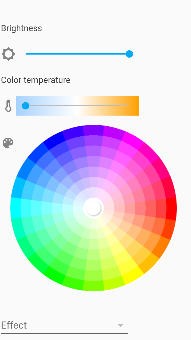
robertgall
on 24 Mar 2019
Ah good. I was hoping that I had everything set correctly so I could start working on the Home Assistant/MQTT integration.
spiku
on 24 Mar 2019
To save yourself hours of wasted time read below, but in summary, use 6.5.0 Tasmotat firmware and via the device console ensure you set SetOption19 1
https://community.home-assistant.io/t/sonoff-tasmota-started-regularly-showing-unavailable-on-home-assistant/90157/90
robertgall
on 24 Mar 2019
Hi everybody, I succesfully flashed a MagicHome LED v2.3, modified the template and SetOption68 to 1. Now I can drive correctly Red color on Channel1, Green color on Channel2, and Blue color on Channel3, but I'm facing the problem that I can Power on/off Channels 2 and 3 only if Channel1 is on, it's like the Channel1 acts as a main power.
Somebody faced the same? Maybe I'm missing some configuration? I tried to read all topics and wiki, but couldn't find anything
Led Driver has 3 channels.
 Cris-T
on 21 Nov 2019
Cris-T
on 21 Nov 2019
This is fixed in PR #6894. Please use the latest version.
 s-hadinger
on 21 Nov 2019
s-hadinger
on 21 Nov 2019
This is fixed in PR #6894. Please use the latest version.
It works now! You are awasome! Thank you
Cris-T
on 21 Nov 2019
Related issues
 ximonline
·
3Comments
ximonline
·
3Comments
 TylerDurden23
·
3Comments
TylerDurden23
·
3Comments
 abzman
·
3Comments
abzman
·
3Comments
 renne
·
3Comments
renne
·
3Comments
 JoergZ2
·
3Comments
JoergZ2
·
3Comments
Most helpful comment
Well I worked mine out. Color order was just a case of switching the PWM1 and PWM2 because my LED strip is +GRBW. Then set some of the unused GPIO's to GPIO_USER and then tried them as PWM4 on the module configuration screen.
Actually the first one I tried was correct, I found the White PWM on GPIO15.
So here's what worked for my MagicHome LED v2.3 (ESP-IR-B-v2.3 / ESP8285MOD ESP-M2)
 { "Arilux LC01",     // Arilux AL-LC01 (ESP8285) - MagicHome LED v2.3 (ESP-IR-B-v2.3 / ESP8285MOD ESP-M2)
                       //  (PwmFrequency 1111Hz)
     GPIO_KEY1,        // GPIO00 Optional Button
     0,
     GPIO_LED2_INV,    // GPIO02 RF receiver control
     0,
     GPIO_IRRECV,    // GPIO04 IR or RF receiver (optional)
     GPIO_PWM2,        // GPIO05 RGB LED Red
     0, 0, 0, 0, 0, 0, // Flash connection
     GPIO_PWM1,        // GPIO12 RGB LED Green
     GPIO_PWM3,        // GPIO13 RGB LED Blue
     GPIO_USER,       // GPIO14 ??
     GPIO_PWM4,       // GPIO15 RGBW LED White (optional - set to PWM4 for Cold White or Warm White)
     0, 0
  },
@app41