Tasmota: Moving average for Power Measurement
Have you look for this feature in other issues and in the wiki?
=> YES
Is your feature request related to a problem? Please describe.
=> I have a few power measurement devices (Blitzwolf/Sonoff/Gosund) and noticed that some of them show really big fluctuations, e.g. I measured a 15W bulb and get measurements values of 13-19 Watts. This happens in particular with Gosund 111 / Blitzwolf SHP6 . On the contrary, Sonoff Pow, Gosund1, Gosund SHP2 seem to be pretty stable (fluctuations of +/- 1 Watt only)
Describe the solution you'd like
_A clear and concise description of what you want to happen._
=> I would like to have a moving average filter. The current sample rate or update rate of the values shown in the webinterface seems to be around 1-2 Hz. I would suggest a moving average filter which calculates the average of e.g. 10 measurements before displaying or publishing it. Obviously the refresh rate of the data shown in the webinterface will be lower, but getting an update e.g. every 10 or 20 seconds would be acceptable for me. This filter could be adjustable through the console, e.g. "movingaverage 0" or "movingaverage 50" . Maybe an IIR filter also will do the job.
Describe alternatives you've considered
=> I tried to implement a moving average filter in home automation software FHEM.
This works, however I had to set the teleperiod to a very low value (10s) which imposes
a lot of traffic on my mqtt/fhem server
Additional context
=> I posted this on fhem forum, too :
https://forum.fhem.de/index.php/topic,90220.msg875650.html#msg875650
In the subsequent posts and elsewhere on the same forum I found at least 3 users more which had the same problem I had.
(Please, remember to close the issue when the problem has been addressed)
 rasti70
All 125 comments
Hi,
Your idea of doing some type of data processing for the power measurement is nice, but there are some points to be taken into account:
If the 15W bulb you are measuring is a cheap one, it will have a lot of noise that it is being injected in your mains AC. Also if you have other devices of that type, you will be having much more noise. There are some of these cheap ones that have a noise switching power supply and I saw others that have a capacitive power supply that produces a huge amount of noise that it is just an additive noise, not a random noise.
So, the moving average filter won't work in an additive noise environment. If the noise is just white noise type or pink noise type, a moving average filter will do the job. In an environment where you have an asymmetrical noise, a moving average filter will give you all the time a higher value than the real one.
An IIR or FIR filter will do the job but only if it is tuned to be a low pass filter to filter those noise spikes. Anyway, the sampling rate for power measurement needs to be adjusted to be a multiple of the switching frequency (this needs to be adjusted experimentally).
So, as you have explained that this power fluctuations only happens in those devices but not in for example a Sonoff Pow, and that this needs a little more complex processing rather than just a moving average in order to have a little more accurate measurement, I think it is not going to be added soon. I would like to know other opinions also.
Anyway, your idea and your request is nice.
A workaround for now so as to have more precise power measurements is to use devices like sonoff pow R2 or the PZEM sensor supported by Tasmota.
Thanks for sharing your ideas :+1:
 ascillato
on 24 Dec 2018
ascillato
on 24 Dec 2018
Hi,
thanks for your swift reply.
The bulb I have is an old fashioned conventional 15W light bulb with filament, thus almost a 100% ohmic resistor which doesn't add noise at all. I think it's the wifi socket switch itself which causes trouble. Of course I can use another device but I'd really like to have a solution for this Gosund 111 / Blitzwolf SHP6 , because these are really tiny and so nice to look at. Maybe its small form factor is the reason for the fluctuations because it favours inductive or capacative coupling. I immediatly flashed them with tasmota so I didn't try the original firmware and app at all but I suppose the original manufacturer firmware or app also uses some kind of data value smoothing algorithm because they should have the same raw measurement values.
rasti70
on 24 Dec 2018
I notice the same behaviour as you do. Most energy sensors are kind of stable but my shp6 acts the same as yours.
 arendst
on 24 Dec 2018
arendst
on 24 Dec 2018
I notice the same behaviour as you do. Most energy sensors are kind of stable but my shp6 acts the same as yours.
OK so what would you suggest ? Do you think implementing some kind of prefiltering in tasmota is an option or do I simply need to live with the poor measurement result of the SHP6 ?
rasti70
on 24 Dec 2018
As a low power measurement takes some seconds you would need to calculate the average over 12 seconds. In that time the load could have been switched off or changed so that makes it very dificult to calculate.
I'm afraid we have to live with it unless some clver dicky finds a quick filter option.
arendst
on 25 Dec 2018
Yes of course that's the price for it. Nobody will find a quicker filter. I already wrote it before : "Obviously the refresh rate of the data shown in the webinterface will be lower, but getting an update e.g. every 10 or 20 seconds would be acceptable for me"
So I currently see 3 options
- wait for better hardware versions (delivering better raw data) of SHP6 like devices or
- accept the poor data without any filtering or
- implement a slow software filter
rasti70
on 25 Dec 2018
I do this with my own code on my server. There's no need for a delay to collect measurements; just use a rolling average.
set lastMeasurement to saved value, or zero if none.
measurement = (( 2 * lastMeasurement ) + newMeasurement) / 3
lastMeasurement = measurement
This will cause a ramp-up for the measurement over the measurement period, and a ramp-down when usage returns to zero. Fluctuations are smoothed over the samples. I use this with temperature and humidity readings as well, since they can similarly fluctuate.
An example in bash:
$ lastMeasurement=0
$ newMeasurement=100 ; # <=== 100W device turned on
$ for i in $(seq 1 14); do measurement="$(echo "scale=2;measurement=(((2*$lastMeasurement)+$newMeasurement)/3);measurement"|/bin/bc -q)" ; lastMeasurement=$measurement ; echo $(printf "%0.f" $measurement) ; done

33
56
70
80
87
91
94
96
97
98
99
99
99
100

$ newMeasurement=0 ; # <=== Device turned off
$ for i in $(seq 1 14); do measurement="$(echo "scale=2;measurement=(((2*$lastMeasurement)+$newMeasurement)/3);measurement"|/bin/bc -q)" ; lastMeasurement=$measurement ; echo $(printf "%0.f" $measurement) ; done

66
44
30
20
13
9
6
4
3
2
1
1
0
0
Edit: decreased the number of samples to speed up the convergence, and added an example of the ramp-up/down.
 MaceMoneta
on 25 Dec 2018
MaceMoneta
on 25 Dec 2018
Your method is really good for smoothing data with white noise.
If you have unbalanced noise, that method will show a value greater than the reality.
For example if you have a 15w bulb, so 15 should be the real value, but if that bulb is noisy with spikes only greater than 15w like
15, 18, 15, 15, 16, 14, 19, 16, 15, 15
Your smooth value will be higher than the real 15 because of this spikes in the measurement.
If you have a IIR tuned as low pass filter, you should have a more accurate value for that case.
Anyway, your algorithm will show a more stable value than the actual raw measurement.
ascillato
on 25 Dec 2018
15, 18, 15, 15, 16, 14, 19, 16, 15, 15
to eliminate spikes in a test series do not use average calculation, use the median:
14, 15, 15, 15, 15, 15, 16, 16, 18, 19 (=15)
and everything is fine. Works also with raising/falling value.
Disadvantage of all statistical methods is the time delay of between real value and displayed one.
 curzon01
on 25 Dec 2018
curzon01
on 25 Dec 2018
Disadvantage of all statistical methods is the time delay of between real value and displayed one.
Correct. And (at the moment) in order to apply any statistical method (smoothing), all the data needs to be transfered from the front end (socket with tasmota) to the server which performs the filtering.
Instead of transfering raw data through e.g. MQTT to do the filtering on a separate server, this should be done right at the frontend.
rasti70
on 25 Dec 2018
A resistive load such as a 15W light bulb may also not remain 15W due to fluctuations in temperature and of course the source voltage. Also, calibration with a 15W load on a device that can measure 2.2KW may not give an accurate enough value for calibration purposes.
15W of 2200W = ~0.6% so it would be nearly impossible to get an accurate calibration figure from this.
 andrethomas
on 25 Dec 2018
andrethomas
on 25 Dec 2018
@andrethomas : Calibration at a single load and the resulting precision within different load ranges is a completely different issue.
Again: I opened this issue because of high fluctuations of the raw data and I asked for a software filter at the frontend (i.e. integrated in tasmota). I implemented such a filter at the backend (home automation system FHEM) and it works as it should. I want the same filter or something similar in tasmota in order to avoid the massive transfer raw data to the mqtt/fhem server. First raw data processing is one of the most inherent tasks of an intelligent front end - and should not be done by the home automation system.
rasti70
on 25 Dec 2018
As @andrethomas said, this is a hardware limitation, so any data processing added to this will make a marginal improvement to the measurement and also to be used only for lower power measurement values. At higher power values, this noise should not be present.
Anyway, the median approach from @curzon01, I think that will result in a more stable and real measurement and also faster than IIR or moving average methods.
I don't know if that processing will be better to be added in Tasmota or in the home automation software itself.
ascillato
on 25 Dec 2018
@rasti70
Calibration at a single load and the resulting precision within different load ranges is a completely different issue
Technically incorrect - they are related.
I do not think implementing filtering on Tasmota side is viable as filtering strategies will change depending on use case - i.e. resistive load vs. inductive loads, just to give a simple differential example... lets not forget about switch mode loads :)
So my recommendation is not to implement filtering on Tasmota side at all.
andrethomas
on 25 Dec 2018
@rasti70
From the technical side and calibration measurement theory, a one point calibration should be done close to the maximum rating in order to have the minimal error all over the range. So, if you calibrate any device with a low value, the error is much bigger than calibrating from a bigger value.
Anyway, the spikes in the raw values is indeed as you explained a hardware limitation.
 ascillato2
on 25 Dec 2018
ascillato2
on 25 Dec 2018
I don't know if that processing will be better to be added in Tasmota or in the home automation software itself.
In very inert systems (temperature for example) it is not a problem to do first transmit the data to the home automation system and then do the filtering. Power measurement is different. Of course loads can change quickly, however, I think that a time resultion of 10-20 seconds is an acceptable tradeoff to get rid of these nasty fluctuations.
rasti70
on 25 Dec 2018
I think that a time resultion of 10-20 seconds is an acceptable tradeoff
Your opinion. I reject this from a technical perspective though :)
andrethomas
on 25 Dec 2018
From the technical side and calibration measurement theory, a one point calibration should be done close to the maximum rating in order to have the minimal error all over the range. So, if you calibrate any device with a low value, the error is much bigger than calibrating from a bigger value.
Ideally, for precision , we should calibrate at a few points e.g. 0.1W , 1W, 10W, 100W,1000W.
But better advance one by one - this field is so ample, we could open another topic for that.
rasti70
on 25 Dec 2018
I think that a time resultion of 10-20 seconds is an acceptable tradeoff
Your opinion. I reject this from a technical perspective though :)
I don't want a Wifi oscilloscope..
I need a nice looking wifi socket switch with energy monitoring function.
rasti70
on 25 Dec 2018
I need a nice looking wifi socket switch with energy monitoring function.
Let me know when you find one that does not require hiding its inefficiencies by averaging output data :)
andrethomas
on 25 Dec 2018
Let me know when you find one that does not require hiding its inefficiencies by averaging output data :)
I fear we won't see such a device at a reasonable price in the near future.
For that reason I made this request .....
rasti70
on 25 Dec 2018
I think there's an important part which you are not completely grasping though.
Below is my mains input as measured by an industrial grade voltage sensor.

Over a 24 hour period an hysteria of up to 5% is observed on the AC supply voltage to the house.
Lets assume a 50W light bulb for calculation purposes, which is rated at 50W 220V so theoretically should draw around 227mA @ 220V meaning an effective reactive resistance of 968 ohms.
If we apply ohms law and bump the input voltage by 5% up to 232V and assume the internal resistance of the bulb remains 968 ohms this would translate to ~240mA - or recalculated to a wattage would mean ~55W - Aside from the additional unwanted 5W of power what is more interesting to note is the physics behind the math and what the math tells us about the physics - we bumped our voltage up by 5% but our power demand increased by 10%! Weird, huh?
In reality things are a little different though.
If you ever find yourself in posession of a variable transformer you should take the oppertunity to play with it a little and see what kind of hysteria is injected in your theoretical model of how things should work in an ideal environment.
If you were not a programmer you would get terribly confused by the following if statements (which actually mean the same thing)
if (known == unknown) { }
if (unknown == known) { }
So I'll leave you with that and, of course, that adding a software filter to fix a hardware problem has no place in the firmware itself... you may of course post process the data in your HA software by all means necessary for any particular use case.
andrethomas
on 25 Dec 2018
I think there's an important part which you are not completely grasping though.
I don't think so.
Below is my mains input as measured by an industrial grade voltage sensor.
Over a 24 hour period an hysteria of up to 5% is observed on the AC supply voltage to the house.
we bumped our voltage up by 5% but our power demand increased by 10%! Weird, huh?
This is only weired for people living in a linear world.
P=(UxU)/R and 1,05*1,05 =1,10
So not weired at all.
In reality things are a little different though.....
Sorry I don't understand what you want to tell us with all the rest so I won't comment on it.
So I'll leave you with that and, of course, that adding a software filter to fix a hardware problem has no place in the firmware itself...
Intelligent sensors do exactly perform that task : Data prepreprocessing which in many cases means data smoothing. But, useless to discuss this further more, we obviously have different opinions about that.
you may of course post process the data in your HA software by all means necessary for any particular use case.
I explained above, why this is not a good solution: Massive raw data transfer to the home automation server.
I don't understand why you're fighting so enthusiastically against my suggestion: Filtering should be an option, not default. If it's implemented in the software, you are not obliged to use it.
rasti70
on 25 Dec 2018
Massive raw data transfer to the home automation server.
Unless you're sending tens of thousands of MQTT messages per second you won't even make a measurable impact on a Raspberry Pi A+ running mosquito and node-red.
I don't understand why you're fighting so enthusiastically against my suggestion: Filtering should be an option, not default. If it's implemented in the software, you are not obliged to use it.
I'm not fighting it, just questioning the need for it. Make a PR if you feel that way inclined :)
andrethomas
on 25 Dec 2018
This post is interesting. Let's summary ideas so far:
- Why to add this processing for spikes in power measurement?
The devices
Gosund 111
Blitzwolf SHP6
have a really bad repeteability of power measurements for lower power loads < 100w.
The rest of power measurement capable devices and sensors supported by Tasmota have a better resolution.
- Where to add or not the processing for spikes in power measurement in HA software or in Tasmota?
In HA software: Can be added any type of processing and representation customized for each use-case. IIR, FIR, moving average filters, statistical median or others. (ACTUAL WORKAROUND)
In Tasmota: Can be added a simple processing that uses few flash and few RAM and don't block Tasmota for other tasks.
- What to add?
In the case of adding to Tasmota seems that a statistical median would smooth the readings, limiting spikes and having a close-to-real values.
Could be taking 9 samples (Round(Teleperiod/9) sampling rate?) ordering from lowest to highest and displaying in the teleperiod message the sample number 5.
- When to add?
Theo is the owner and the one deciding to add it or not. So, I think he was clear saying that it is needed that someone can prove a fast and light method to improve those devices.
So, this request is on hold up to someone would like to program, test and prove a enhancement for those devices.
As a workaround for now is to use another power measurement device or a PZEM sensor for more stable power measurements lower than 100w, or process the data in your home automation software.
Thanks everyone for sharing theirs ideas. Very interesting and very appreciated.
ascillato
on 25 Dec 2018
Thank you Adrian for your summary.
So if Theo as the owner decides to add, we still need a volunteer to implement such a routine.
I think that the small simple median-like subroutine as Adrian mentioned above is already sufficient. Or any other filter, algorithms are standard and C-coded examples can be found on the www, e.g. https://atwillys.de/content/cc/digital-filters-in-c/
However, I won't be the volunteer to program that. I can't.
If I could program, I would have done it already myself. I have written small pieces of c-code many many years ago when I was a student. The subroutine itself probably will not the problem, this should be a rather small piece of code, however when I look at the current tasmota code this is so overwhelming that I don't even know where I should start, which arguments to hand over from which function etc.
But in any case I would volunteer for testing.
rasti70
on 25 Dec 2018
@ascillato I'll write a compact filter class for Tasmota so it can be re-used by other sensors where necessary. For now, I'll just add a class for median filtering but we can add other strategies as and when needed.
andrethomas
on 26 Dec 2018
@ascillato I'll write a compact filter class for Tasmota so it can be re-used by other sensors where necessary. For now, I'll just add a class for median filtering but we can add other strategies as and when needed.
Thank you Andre. Sounds good. !! Please let me know where and how this is available for testing.
rasti70
on 27 Dec 2018
I've made a PR for the SensorFilter library here https://github.com/arendst/Sonoff-Tasmota/pull/4741
Included is a change I made for the LM75AD temperature sensor which uses 5 elements whilst picking element number 3 (the midpoint) as the new value which will be used.
If and how Theo will implement this in the Gosund 111 / Blitzwolf SHP6 driver is not up to me.
andrethomas
on 27 Dec 2018
See #4741 for intermediate comments.
Continuing on the SHP6, from what I see as current values I guess the sensor is mounted before the SHP6 logic and therefor if a load of 25W with powerfactor 1 (incandescent bulb) the current jumps up and down from 0,137A to 0,190A measuring both bulb and SHP6. Why power jumps up and down from 23.1W to 27.1W beats me as I'm quite sure the SHP6 doesn't draw 4W...
arendst
on 27 Dec 2018
I do not have an SHP6 but I'll order one as soon as BG has them in stock.
@arendst Have you measured the current consumed by the SHP6 on the input side when it is turned on but has no load connected to it? It should be around 0.4W without being turned on and perhaps a little more if the device is allowing power through without a load connected to it.
andrethomas
on 27 Dec 2018
0.4 W would be wonderful.
It's rather 0.8 (off) - 1.1 (on) watts
rasti70
on 27 Dec 2018
@rasti70 Is that measured between live AC and the device using a DMM?
andrethomas
on 27 Dec 2018
It has been measured with a simple cheap energy monitor. Ebay # 132836883619
maybe not too precise, however, the wattage reflects the experience of other fhem users.
rasti70
on 27 Dec 2018
The ESP cannot consume more than 0.4W at maximum and will be closer to 0.1W on firmware version 6.3.0.10 and higher. The 0.3W variance between on and off (60mA @ 5V for the relay) seems in line with what I get with ebay relay boards given they also have a led (~20mA) on them - They measure in at 80mA.
So there's a phantom 0.1W-0.7W floating around somewhere in the rest of the electronics.
andrethomas
on 27 Dec 2018
Greeting all, here is for an inspiring 2019, this is a fascinating discussion.
At the risk of going off topic and excuse me if I am posting in the wrong place.
I'm developing a couple of energy switch designs at the moment and I am wanting to contribute to the tasmota code where possible.
The first is a 30amp 1 1/2 HP motor start Songle SLA-5VDC-SL-A , HLW8012 / 7W 0.001 shunt theoretically can run to 83 amps. Current Sensing is done in the Neutral and the esp is at ground. The current enclosure is in IP68, with DS18B20 included, It's designed for pool pumps, electric storage heaters ect.
If you are interested for a sample PM me, we are due to finish the first production pilot mid January.
The second is a 3 phase unit with sensing in each phase and neutral (to be decided) for bore pumps and 3 phase heating/motor applications.
Anyway my point from this conversation, where do I begin to start understanding the tasmota frame work, it is overwhelming. Who is best to communicate with around HLW8012 code enhancements?
I would say I'm a beginner at programming but I want to learn and I want to study tasmota, my background is Industrial Electrical construction/engineering.
I echo this.
"If I could program, I would have done it already myself. I have written small pieces of c-code many many years ago when I was a student. The subroutine itself probably will not the problem, this should be a rather small piece of code, however when I look at the current tasmota code this is so overwhelming that I don't even know where I should start, which arguments to hand over from which function etc."
 flashtel
on 30 Dec 2018
flashtel
on 30 Dec 2018

flashtel
on 30 Dec 2018

flashtel
on 30 Dec 2018
I have 10 development boards available now, it's now using the ESP-WROOM-02 module to work with the pick and place machine and this module has FCC certification. I am applying for SAA certification in Australia and will be pursing US / EU certification after that. The production run is using a better case as well. I can send you a dev board/enclosure now if you are interested to assist in integrating with tasmota. The New Year is starting, it's an exciting time. Enjoy Paul
flashtel
on 30 Dec 2018
Anyone noticed that DMM shows around 10V AC on SHP6 while is off ?? I was expecting 0 like on POWr2.
 KPK75
on 30 Dec 2018
KPK75
on 30 Dec 2018
Anyone noticed that DMM shows around 10V AC on SHP6 while is off ?? I was expecting 0 like on POWr2.
try to take the shp6 out, turn it 180° and plug in again. Do you still measure a voltage when switched off ?
rasti70
on 30 Dec 2018
Normally it can't be done ( "french" connector ). But I have tested on the socket wihout ground and it shows 1.5 V AC when put upside down. Dangerous.
KPK75
on 30 Dec 2018
OK. Just measured the same. Approx. 1.7V AC when the relay switches L1 and different voltages from 20-40V AC (I connected&diconnected a few times to make several measurements) if the relay switches N .
I just compared that to a "quality product" of a renowned German brand.
https://www.elv.de/fs20-funk-schalt-spar-set-3-mit-1x-fs20-s8-3-3x-fs20-st-4.html
Same result.
I currenly have no idea if this residual voltage when switching L1 is dangerous or not.
Switching only N instead of L1 is definitly dangerous, however, almost all
switchable sockets on the market are constructed that way (to switch only 1 of the 2 conductors)
rasti70
on 30 Dec 2018
I accidently touched wires while calibrating the device ( relay off ) and it wasn't nice.
And Sonoff POWr2 shows 0 while off.
KPK75
on 30 Dec 2018
I accidently touched wires while calibrating the device ( relay off ) and it wasn't nice.
So better don't do that again....
But : If you can insert the switch in the outlet only in one position and if then
you switch N instead of L1 with the SHP6 then your electrical installation
at home is faulty.
rasti70
on 30 Dec 2018
I accidently touched wires while calibrating the device ( relay off ) and it wasn't nice.
And Sonoff POWr2 shows 0 while off.
The POW's can display voltage while the relay is off using SetOption21
But yes, touching anything metal on devices that are plugged in (be it off or not) is a job best left for rubberman :)
andrethomas
on 31 Dec 2018
I received 2 gosund SP111 = Blitzwolf SHP-6
A 40 W bulb (old Edison type) Measured voltage and current

and after calibrating (with Voltage an Power=Watt) i get this output:

 Jason2866
on 31 Dec 2018
Jason2866
on 31 Dec 2018
So Apparent and Reactive Power is completly wrong!
Power Factor has to be 1

Jason2866
on 31 Dec 2018
If your 40W value is stable over time, you are lucky. My shp6 is fluctuating.
Apparent and Reactive Power is also wrong with other plugs, e.g. SHP2 / SP1
rasti70
on 31 Dec 2018
Second SP111 has same false Power Factor

Jason2866
on 31 Dec 2018
@rasti70
I think the fluctuating is a result of the wrong Power Factor. 99mA from nowhere...
Jason2866
on 31 Dec 2018
@rasti70
I think the fluctuating is a result of the wrong Power Factor. 99mA from nowhere...
Who knows....
BUT: Power Factor is also wrong with other devices (I have 2xSHP2 and 2xWuudi)
but these don't show fluctuating real/active Power values.
rasti70
on 31 Dec 2018
Did you calibrate current too?
If not the power factor will be wrong resulting in wrong apparent and reactive power too. They are all calculated from the only measurable values voltage, current and power.
arendst
on 31 Dec 2018
I measured voltage and power with a light bulb.
Calculated current from that.
Then I calibrated all three values: power, current, voltage.
rasti70
on 31 Dec 2018
What kind of light bulb?
andrethomas
on 31 Dec 2018
If your measured power is 40W (P) and your Voltage is 229V (U) then your calculated current is P / U is 0.182A.
Using command currentset 0.182 should change the current from 0.345 to 0.182 and the power factor to around 1. This will also have effect on the reactive- and apparent-power.
arendst
on 1 Jan 2019
Thx @arendst
missed to set CurrentSet to my measured Value. Did the wrong suggestion that Voltage and Power is enough.
Now Power Fakcor is solid 1.00. Just measured current is now fluctuating from 33W to 40W
I think this is a hardware issue from the device... The measurement resistor is small.
Jason2866
on 1 Jan 2019
Power factor should always be 1 on a resistive load. Its only led bulbs and other pwm/switch mode based power supplied devices and inductive loads like motors that will have a PF of < 1.0 - We should actually add this in the wiki - calibration should always be done on a resistive load which will confirm plausible calibration by giving a PF of 1.00
andrethomas
on 1 Jan 2019
Yes, but weired thing is that on my second SP111 Power Factor jumps...
Calibrated with 230 V 172,9 mA and Power 39,76 Watt
First device gets Power Factor 1.0 (most of the time)
Second device Power Factor is fluctuating frm 0,9 to 1.00 If power factor is 1.0 measured Power is always correct
Jason2866
on 1 Jan 2019
Hello,
I can confirm the behaviour reported by Jason2866.
1) I checked my lowcost energy monitor with a DMM and found that its precision is really bad.
So I got this one https://www.elv.de/elv-energy-master-basic-energiekosten-messgeraet-1.html
and this shows almost the same values as my DMM .
2) I recalibrated the shp6 with the nedw setup. Also important to mention that this time I
placed the powermeter/DMM after the shp6.
3) I measured again and logged some values for 5 minutes.
PowerDelta has been set to 10 for logging. See file attached.
Columns BD contain the relevant data.
I copy&pasted the first of these values into a new table (columns E to J)
Maybe someone experienced in excel can do this automatically...
rasti70
on 1 Jan 2019
SUCCESS
Got it working Device needs exact calibrating AND you have to set Sleep 0
now fluctuations of +/- 1 Watt only.
This seems correct to me too because Voltage was changing a little too
Jason2866
on 2 Jan 2019
SUCCESS
Got it working Device needs exact calibrating AND you have to set Sleep 0
Sleep0 is set by default and I only changed it for the switches (such as sonoff basic or S20)
now fluctuations of +/- 1 Watt only.
This seems correct to me too because Voltage was changing a little too
Which is the mean when you mesure +/- 1 Watt ?
5 W , 100W or 1000W +/- 1 Watt ?
I can't reproduce such a low fluctuation....see log above.
rasti70
on 2 Jan 2019
@rasti70 sleep is 50 by default. Try command sleep 0 please
ascillato2
on 2 Jan 2019
According to https://github.com/arendst/Sonoff-Tasmota/wiki/Commands default value for sleep is 0.
When I enter sleep in the console window, this is confirmed =>
16:06:06 CMD: sleep
16:06:07 MQT: tele/Mess_Steckdose_6/RESULT = {"Sleep":"0 (0)"}
I have Tasmota 6.3.0.5 on all devices.
rasti70
on 2 Jan 2019
With a bulb with 40 Watt i have 1 Watt fluctuation.
Yes before proper calibration i had the same fluctuations
Upgrade you firmware to latest. Version 6.3.xxx is pretty old and outdated
Jason2866
on 2 Jan 2019
Thanks for reporting about the wiki. It was outdated for latest Tasmota. I have just updated it. Thanks.
Please, update to latest Tasmota version and try again.
ascillato
on 2 Jan 2019
Hello,
now I tried to update to latest tasmota but I got an error message while compiling, see attachment error.txt
I can't use the precompiled binaries (for several reasons, e.g. I need MQTT 3.1 and not 3.1.1.....)
I therefore uncommented #define USE_IR_REMOTE and then the file was compiled.
I use the ATOM editor latest version, latest everything, all is updated
Then I tried to make an update using the tasmota webinterface.
I got the following error message:
BlitzWolf SHP2 Modul
Mess_Steckdose_5
Upload fehlgeschlagen
Upload-buffer-Vergleich weicht ab
Can you help ?
rasti70
on 2 Jan 2019
Firmware size in kbyte?
Your SetUp is faulty.
It does compile without any error or warning with #define USE_IR_REMOTE
I wouldnt trust your compiled firmware.
Jason2866
on 2 Jan 2019
Please, try the precompiled bins from development branch at http://thehackbox.org/tasmota/ just for testing the variance of power measurement. If that works fine, as the test from Jason, then we can search for the problem in your building setup.
ascillato
on 2 Jan 2019
Please, try the precompiled bins from development branch at http://thehackbox.org/tasmota/ just for testing the variance of power measurement. If that works fine, as the test from Jason, then we can search for the problem in your building setup.
I was able to update with the precompiled bins. MQTT and logging not used, just looking at the webinterface. Same result as before. No stable values for current and active power and many unreasonable values (unequal 1) for power factor.
rasti70
on 2 Jan 2019
Firmware size in kbyte?
523376 byte (Before it was 506848 byte)
Your SetUp is faulty.
How can I find out what exactly is faulty ?
It does compile without any error or warning with #define USE_IR_REMOTE
It compiles without any errors/warnings if IR remote is not used =>
// #define USE_IR_REMOTE
rasti70
on 2 Jan 2019
How can I find out what exactly is faulty ?
You read, explore, try to understand... when tired you to go sleep... when you wake up you start at the beginning again.
You can repeat this process until you find what is faulty.
andrethomas
on 3 Jan 2019
@rasti70
Have you follow the same steps than Jason?
- erase all flash with esptool.py
- flash with esptool.py the latest tasmota from development
- configure your wifi
- set SLEEP 0
using a 60W bulb:
- calibrate CurrentSet
- calibrate VoltageSet
- calibrate FrequencySet
- calibrate PowerSet
And then Test
ascillato2
on 3 Jan 2019
Have you follow the same steps than Jason?
I flashed OTA with the latest tasmota from development, configured my wifi, set SLEEP 0, using a 15W bulb calibrated CurrentSet, VoltageSet, did not calibrate FrequencySet, calibrated PowerSet
And then Tested
And had the same bad results as before (power factor = 1 in most of the cases, but unequal 1 many times, active power fluctuating from 13-19 Watts)
rasti70
on 3 Jan 2019
15w is too low for a calibration. The recommended is 60w. Do you have 3 or 4 bulbs to put all together for calibration?
ascillato2
on 3 Jan 2019
I tried now a 60W bulb with new tasmota.
Active Power is fluctuating between 57-63 Watts.
When I connect the 15W bulb then (without new calibration), variation is between 13-19W.
The voltage shown in the Webinterface is less or more stable (varies a little bit over time) and matches exactly the voltage of my energy monitor
The current and power are fluctuating a lot. Much more than my energy monitor, this does not fluctuate at all -- it's rather very stable.
I performed CurrentSet, VoltageSet and PowerSet. The power value shown in the webinterface seems to be exactly the voltage multiplied with current (if PF=1) . Now I wonder what the effect is if I change the calibration order (1. voltage , 2. current and 3. power calibration). Why the hell do I need to calibrate power if this is the product of calibrated voltage and calibrated current ??
When I calibrate with a 15W bulb and then connect the 60W bulb, I get completely wrong power values (30-40W) for the 60W bulb. If I calibrate with the 60W bulb, the 15W bulb shows reasonable (but fluctuating) values. I connected a 800W toaster then. My energy monitor shows 770W, the tasmota webinterface 660W (and fluctuating).
So next idea, why not calibrate with the toaster. I did that. All values were reasonable, i.e. the 15W bulb showed between 13-19W, the 60W between 60-65W and the toaster wattage was precise in the web interface. However with that toaster calibration, the bulbs showed very unreasable power factors (15W Bulb PF=0.5 and 60W bulb around 0.8...0.9)
These results are not very satisfactory and seem to show a need for data smoothing and segmentwise calibration.
rasti70
on 3 Jan 2019
Why the hell do I need to calibrate power if this is the product of calibrated voltage and calibrated current ??
because of PF
ascillato
on 3 Jan 2019
Why the hell do I need to calibrate power if this is the product of calibrated voltage and calibrated current ??
Because there is a major difference between inductive/capacitive loads and resistive loads. Google for it and learn why you see three type of power in the GUI.
Try a different device than SHP6. All other devices are a lot more stable which indicates the hardware design of the SHP6 is insufficient.
arendst
on 3 Jan 2019
When I calibrate with a resistive load, there is no phase shift between current and voltage and PF=1
I know what a power factor is and a resistive, inductive and capacitive load.
But still don't understand the calibration process.
rasti70
on 3 Jan 2019
Why the hell do I need to calibrate power if this is the product of calibrated voltage and calibrated current ??
Because there is a major difference between inductive/capacitive loads and resistive loads. Google for it and learn why you see three type of power in the GUI.
Try a different device than SHP6. All other devices are a lot more stable which indicates the hardware design of the SHP6 is insufficient.
I have SHP2 and they are much better. But they are not so nice. WAF is very low.
Maybe data smoothing can help to get out better measurment values out of
the insufficient SHP6 hardware. So we arrived at my initial request again.
rasti70
on 3 Jan 2019
To get this device correct calibrated is hell. For this device it would be easier to change direct
the values of VoltageSetCal, PowerSetCal and CurrentSetCal.
Because if you want to fine tune fluctuating shoots your already close config...
IF the device is well calibrated (needs a load about 60W or better more) it is nearly as good as a SHP2!
Jason2866
on 3 Jan 2019
With a resistive load the formula P = U * I can be used to verify to receive a PowerFactor of 1.
So the hardware needs to be calibrated for known power (say a 60W bulb which btw only uses 60W when the voltage is 230V which is normally not the case but that's a minor problem), known voltage and known current. Using the right equipment you just need to enter the correct information using commands powerset, voltageset and currentset``.
So if your 60W bulb is connected to 230V the current should be 60W / 230V = 0.260A. With these parameters set it should also report correct values when a hairdryer or other inductive load is connected.
The SHP6 won't as said before. Most other devices will.
If you can spot the hardware differences you would be the man of the day.
arendst
on 3 Jan 2019
If the voltage isnt set very correct (just on this device!) you can forget all other steps...
An difference from 0.5V makes already all other steps worse/useless
Finally i connected a 2000 W heater. Did make it a little easier.
Jason2866
on 3 Jan 2019
Added the label Feature Request (Hold Over) for future reference.
Summary and workaround in https://github.com/arendst/Sonoff-Tasmota/issues/4727#issuecomment-449873042
Thanks everyone for sharing their ideas.
ascillato2
on 3 Jan 2019
I subscribe to this "bug", here are my logs:
After attaching a 75W classic edison bulb:
20:32:54 CMD: PowerSet 75.0
20:32:54 MQT: stat/blitzwolfshp6/RESULT = {"PowerSetCal":10547}

Voltage    247 V
Current    0.523 A
Power    74 W
Apparent Power    129 VA
Reactive Power    106 VAr
Power Factor    0.57
Next step.
DMM measured voltage 234.5
20:35:57 CMD: VoltageSet 234.5
20:35:57 MQT: stat/blitzwolfshp6/RESULT = {"VoltageSetCal":1851}

Voltage    234 V
Current    0.562 A
Power    80 W
Apparent Power    131 VA
Reactive Power    104 VAr
Power Factor    0.61
Still fluctating a lot between 67-83W on a classic 75W bulb.
20:40:20 CMD: CurrentSet 319.829
20:40:20 MQT: stat/blitzwolfshp6/RESULT = {"CurrentSetCal":1933}
Still fluctating between 69-79W
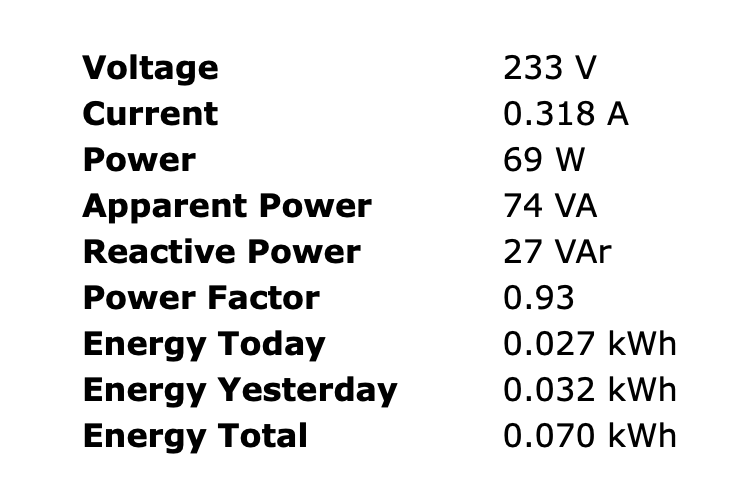
I installed the nightly from http://thehackbox.org/tasmota/sonoff.bin, because there was changes for SHP6.
Voltage    234 V
Current    0.329 A
Power    69 W
Apparent Power    77 VA
Reactive Power    34 VAr
Power Factor    0.89
Still fluctating a lot.
 adrianmihalko
on 5 Jan 2019
adrianmihalko
on 5 Jan 2019
Try the latest dev from late this afternoon. Major changes in current and power handling for shp6.
Oops just read you already did.
arendst
on 5 Jan 2019
I tried this:
sonoff.bin | http://thehackbox.org/tasmota/sonoff.bin | 523k | 20190105 23:01 GMT+2 | sonoff.map.gz | de996cb
This is not that one?
adrianmihalko
on 5 Jan 2019
Yes that's the one.
You may need to recalibrate as calculations have changed a bit. Fine tune using PowerCal, VoltageCal and CurrentCal.
arendst
on 5 Jan 2019
@adrianmihalko :
Do you see that powerfactor of unequal 1 all the time ?
I was able to bring this to 1 with a calibration (of power current and voltage, see posting above).
But it was still fluctuating very much (old firmware)
I fear this is an inherent property of the shp6 hardware:
Very small measurement shunt results in a very small voltage
which can easily be disturbed due to the EMC-unfriendly tiny formfactor
@arendst :
May I ask what has been changed regarding power handling for shp 6?
PowerCal, VoltageCal and CurrentCal are new commands?
I used Powerset voltageset currentset
rasti70
on 5 Jan 2019
PowerCal VoltageCal and CurrentCal have been reint3oduced as the allow more fine tuning. The had disappeared a few versions ago.
See github commit what has changed. Major parts are better current/voltage calculation by using local variable bypassing global variable which was updated during calculation when high frequency signals are active. Using power calculation mean instead of jusr a single value every 200mSec.
arendst
on 5 Jan 2019
OK, sounds good. I'll try. So I need to use PowerCal VoltageCal and CurrentCal and not Powerset voltageset currentset for the SHP6 ?
rasti70
on 5 Jan 2019
23:28:48 CMD: PowerSet 75.0
23:28:48 MQT: stat/blitzwolfshp6/RESULT = {"PowerSetCal":11806}
23:29:04 CMD: PowerSet 75.0
23:29:04 MQT: stat/blitzwolfshp6/RESULT = {"PowerSetCal":11331}

23:31:32 CMD: VoltageSet 232.1
23:31:32 MQT: stat/blitzwolfshp6/RESULT = {"VoltageSetCal":1880}

23:34:40 CMD: CurrentSet 323.136
23:34:40 MQT: stat/blitzwolfshp6/RESULT = {"CurrentSetCal":2181}
It is better now:
Power Factor 0.90-1.00
Power: 65-82W
but the fluctuation is much (s)lower.
adrianmihalko
on 5 Jan 2019
I assume you only measured voltage , took the 75W reading of the bulb and calculated the current.
Do you have 2 DMM to measure voltage and current the same time ? This would be better.
Also, from Powerset to currentset it took you 5 minutes.
Keep in mind that voltage may fluctuate/change as well during this long time.
At least in my home....
rasti70
on 5 Jan 2019
I have only one, but somewhere I have a power meter, but I must find it. I report back ASAP.
adrianmihalko
on 5 Jan 2019
Try latest changes with build:
https://github.com/arendst/Sonoff-Tasmota/commit/cb8963a7bff8463f061e6435bd07a2d1409f8cd0
Jason2866
on 6 Jan 2019
I just tried that. Not perfect but much much better.
Result / what I did so far =>
1) calibrated with 60W bulb
- powerfactor shown mostly equal 1, maybe 1/6 values unequal 1
- wattage shown is stable, 60W +- 2W
2)connected a 15W bulb using the above (60Wbulb-)calibration
- power factor shown is around 0.5 - but stable
- wattage shown is unstable 15W +/- 3W
3) I performed a calibration with that 15W bulb
- power factor shown is 1 - and less or more stable
- wattage shown is still unstable 15W +/- 3W (no change compared to #2 )
4) without new calibration (thus still using 15W bulb calibration) I plugged in the 60W bulb
- wattage shown is 30 watts only - but stable
rasti70
on 6 Jan 2019
I see the same.
I'm working on finding out the factor needed to make the non-lineair measurments lineair; If calibrated on one bulb (25W) the measurement is wrong on a 75W bulb.
I've plugged the SHP6 in a good working SHP2 and see indeed the SHP6 is non-lineair. The SHP2 measures flawlessly.
To be continued...
arendst
on 6 Jan 2019
Calibrate with biggest (powerfactor 1) load you have. Will give best results
Jason2866
on 6 Jan 2019
Hi,
I continue to follow this thread with considerable interest.
I had a good look at the shp6 specifications, it looks very promising.
My concern is software programming fault current interruption with this device, without sufficient testing, this is when things are going to ionise/vaporise and has the most potential for injury of 3rd parties.
Please if you could review these resources, I have no commercial or social affiliation with the authors.
https://www.ecmweb.com/content/short-circuit-current
Love your work.
Thanks
Paul
PS for your own interest when working on devices that have the ESP tied to active. (Which is ridiculous)
flashtel
on 6 Jan 2019
@Jason2866 YOU'RE RIGHT!!!
just did calibration with 75W + 75W + 25W. Then if one or two is turned off it tries to show the correct value. It's not that close as the SHP2 but it's near enough.
I stop further analyzing regarding non-linear/lineair and call it a day concerning SHP6.
arendst
on 6 Jan 2019
Calibrate with biggest (powerfactor 1) load you have. Will give best results
Yes I already mentioned that much earlier.
But : the smaller the (ohmic) load then, the worse the power factor shown.
So if you calibrate e.g. with a 2000W water heater, the real power wattage shown for a 60 W bulb still will be OK, however, the apparent power shown and thus Powerfactor shown will go down. If you go further down, you will notice non-linearities in the real power shown as well, I noticed that my 15W bulb shows a mean of around 18 rather than 15W. And fluctuating....
What do you think about using a 10mOhm Shunt instead of a 1mOhm ?
rasti70
on 6 Jan 2019
SUCCESS ! with a modified SHP6
I changed the 1mOhm SMD shunt against one with 10mOhm / 2 Watt (WW25NR010FTL)
Calibrated with 60W bulb and tested with new Tasmota Version (6.4. as of January 6th)
I tried 15W and 60W bulbs and a 800W toaster with that calibration.
Result =>
Excellent stability and correct power factor (almost always exactly 1) with lower and higher ohmic loads, The result is so good that I had to set wattres 1 to see any fluctuation.
The only small inconvenient is the still slightly remarkable non-linearity.
Big question, is that still safe ? =>
1) The SMD shunt power loss itself not a problem,
even with max. 2300W load it dissipates P=10mOhm x 10A x 10A=1 Watt,
while the SMD is rated for 2W
2) Maybe the internal heat production at high loads will increase
internal temperatures to unwanted high levels, however, looking at
the mecanical design, I believe that heat dissipation through the thick solder
at the shunt (and metall plugs) should be really good.
3) The max. power loss with the original shunt was P=10A x 10A x 1mOhm = 100mW
To produce a power loss of 100mW with a 10mOhm shunt, a max current of
I=squareroot (100mW/10mOhm)=3.16A is possible which corresponds to 3.16A x 230V=727W
So even the most cautious user can use such a modified SHP6 up to 727W which is sufficient
for most applications (obviously not for devices such as dryer or washing machine).
Maybe some experienced user can measure internal temperatures (DS18b20 ??) with the old shunt
and the new shunt and determine a reasonable maximum rated power for the modified SHP6
rasti70
on 9 Jan 2019
Nice hack.
Perhaps one could try using a 2mOhm shunt for less dissipation and perhaps more stability too...
arendst
on 9 Jan 2019
I wonder if the one that ships with the product have a 1% tolerance...
andrethomas
on 9 Jan 2019
I wonder if the one that ships with the product have a 1% tolerance...
the shunt tolerance does not contribute to fluctuations at all
rasti70
on 9 Jan 2019
I now tried to measure without the new averaging/mean function, i.e. I flashed an old version of Tasmota (6.3.0.5). The old tasmota also returns stable results.
rasti70
on 9 Jan 2019
Great. So you ruled it out that is 100% the hardware
Jason2866
on 9 Jan 2019
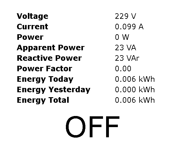
I just flashed a SHP6 with 6.4.1.12. With no load connected it reports:
Voltage 239 V
Current 0.153 A
Power 1 W
Apparent Power 37 VA
Reactive Power 37 VAr
Power Factor 0.02
 SirJMD
on 28 Jan 2019
SirJMD
on 28 Jan 2019
Did you calibrate the device ?
If yes, how ?
rasti70
on 28 Jan 2019
@SirJMD
Device needs exact calibrating!! Connect a great load. Thermal heater...
Jason2866
on 28 Jan 2019
I'm about to calibrate it. Just wanted to post some out-of-the-box numbers. Rather crazy numbers with no load.
SirJMD
on 28 Jan 2019
Hello,
I've been reading this thread, and although I'm not nearly qualified for this type of "language", I've a very vague question that I'd like to see it clarified: to achieve correct measurements from this device it's necessary any hardware change (besides the operation of flashing the tasmota firmware) or it's only a software operation?
 flrsilva
on 4 Feb 2019
flrsilva
on 4 Feb 2019
@flrsilva Reported above means changing the surface mount shunt to a higher resistance value yielded more stable results with this particular device.
andrethomas
on 4 Feb 2019
@flrsilva : The current tasmota version includes a data smoothing algorithm and if you use a Blitzwolf SHP2 or Gosund SP1, the precision of power measurements with Tasmota and no further hardware changes is good enough ( for Joe Doe users). If you intend to use a Blitzwolf SHP6 or Gosund SP111 it's highly recommended to change the 1mOhm measurement shunt with a bigger one. This SMD needs to be changed

(I used 10mOhm and get very good results)
rasti70
on 4 Feb 2019
With no hardware mod I can't get the SHP6 to produce stable measurements. I can get it calibrated to be stable and true at high or low load, but not both.
Calibrated to 1950W ohmic load was straight forward, but at no load it would report 100-150mA purely reactive. Calibrated with 40W ohmic load would result in high loads being way off and having 10-20% reactive power component.
SirJMD
on 4 Feb 2019
With no hardware mod I can't get the SHP6 to produce stable measurements. I can get it calibrated to be stable and true at high or low load, but not both.
Calibrated to 1950W ohmic load was straight forward, but at no load it would report 100-150mA purely reactive. Calibrated with 40W ohmic load would result in high loads being way off and having 10-20% reactive power component.
I can confirm that. This is already described above. But if you use a 10mOhm Shunt you can calibrate at e.g. 60W and you get fine results for both low and high loads (e.g. 5W and 1kW )
rasti70
on 4 Feb 2019
With no hardware mod I can't get the SHP6 to produce stable measurements. I can get it calibrated to be stable and true at high or low load, but not both.
Calibrated to 1950W ohmic load was straight forward, but at no load it would report 100-150mA purely reactive. Calibrated with 40W ohmic load would result in high loads being way off and having 10-20% reactive power component.I can confirm that. This is already described above. But if you use a 10mOhm Shunt you can calibrate at e.g. 60W and you get fine results for both low and high loads (e.g. 5W and 1kW )
The problem with 10 mOhm is that at 10A you dissipate 10 times more than with 1 mOhm, That's quite a alot extra, especially when they already try to mitigate heat from the ESP8266 with a thermal pad.
I have several values of shunt resistors on the way in the mail, and three additional SHP6, so I'm gonna test a few different values and see what works best.
SirJMD
on 4 Feb 2019
I've been following this thread for a while now. And I'm seeing some really interesting progress here, really nice to see how much effort people put into this issue!
But I was wondering:
I've flashed a couple of SHP2's and SHP6's with the latest Sonoff firmware (pretty awsome!) and integrated them into Home Assistant (HA).
I've added some gauges together with the corrosponding switches of the SHP's in HA, to be able to monitor them a bit.
I'm not sure if the given values are updated correctly. But I'm mentioning here that the current values of the SHP6's are verry off, compared to the current values of the SHP2's.
I've read that Power and Voltages are discussed a lot of times, and that people had tried to callibrate these values, but could there be a problem with the current callibration (this bigger shunt makes sense though) since P=U*I?
I'm aware that best results are given to test the diffrent SHP's with the same load ofcoarse.
But my setup gives the following values (at diffrent loads/devices):
- SHP2_01: 82W / 0.366A (230*0.366= 84W)
- SHP2_02: 779W / 3.453A (230*3.453= 794W)
- SHP6_01: 70W / 0.766A (230*0.766= 176W)
- SHP6_03: 4W / 0.143A (230*0.143= 32W)
(there can be a slight difference in Voltage, but just took 230 for the ease of use. so the power calculations can be a bit off)
 Rockel83
on 10 Feb 2019
Rockel83
on 10 Feb 2019
With no hardware mod I can't get the SHP6 to produce stable measurements. I can get it calibrated to be stable and true at high or low load, but not both.
Calibrated to 1950W ohmic load was straight forward, but at no load it would report 100-150mA purely reactive. Calibrated with 40W ohmic load would result in high loads being way off and having 10-20% reactive power component.I can confirm that. This is already described above. But if you use a 10mOhm Shunt you can calibrate at e.g. 60W and you get fine results for both low and high loads (e.g. 5W and 1kW )
So, I was bothered by the bad measurements aswell and took the route of modding the shunt. Put in a 10mOhm resistor and I get very good results when calibrating with a 60W (which measures 55W with a clamp current-meter). I hooked the modded plug to my portafilter coffee machine which pulls a solid 1.8kW/8A when heating. No issues with the temperature of the device so far. BUT, when calibrated to 55W I only get a measurement of around 900W. Other way around, if I calibrate to 1800W, the 55W bulb will show around 100W.
Can you please try this yourself and confirm I am not doing something wrong?
The commands I use for calibration are Voltageset, Currentset and Powerset
 naKruul
on 21 Jul 2019
naKruul
on 21 Jul 2019
So, I was bothered by the bad measurements aswell and took the route of modding the shunt.
Hello,
Is there any tutorial or guidance on how to remove the shunt? I have the SHP6, as well as 5 mohm shunts, but I was totally unable to unsolder the SMD (I actually destroyed it but it's still there).
 Konnichy
on 22 Jul 2019
Konnichy
on 22 Jul 2019
Here are the values reported by my SHP6 plug during a 3d printing session.
As you can see, the reported power consumption jumps from 60W to 120W, with peaks that go up to 250-300W.
This is not normal. Once heated up, the power consumption should stay quite constant.
I haven't made any HW mod to the SHP6 plug. I only flashed Tasmota v6.5.0.
Can you please advise if replacing the 1 mOhm SMD resistor with a 10 mOhm one, would resolve the power fluctuation issues?
Thanks,
Cristian


 tlc76
on 20 Aug 2019
tlc76
on 20 Aug 2019
This is not normal. Once heated up, the power consumption should stay quite constant.
Once heated up the hot end and the bed (if you use a heated bed) will need to remain on whatever temperature setting and these are usually controlled by either intermittent on/off signals or more commonly by PWM - The latter in conjunction with the likeliness that you are using a switch-mode power supply and the fact that the power draw from the stepper motors would not remain constant throughput a print I would say that the results you got are justified.
Can you please advise if replacing the 1 mOhm SMD resistor with a 10 mOhm one, would resolve the power fluctuation issues?
Reducing the shunt resistor will improve accuracy especially on lower current values as it allows for better calibration and measurement results but this will not exempt the device from the laws of physics it is being subjected to as outlined above.
andrethomas
on 21 Aug 2019
@andrethomas - thanks for replying. I'll do a test with the heated bed turned off. I'll also do another test with a Xiaomi smart plug.
Has anyone tested the SHP6 plug with the original factory firmware, to see if the power variations appear as well?
tlc76
on 21 Aug 2019
I think AndreThomas could be perfectly right, I get similar plots for some devices.
What you see is possibly really what you have, so the measuring device is rather an oscilloscope than a simple power meter.
I used the functions powerdelta and powerlow in order to see only "relevant changes"
0:03:23 MQT: tele/Mess_Steckdose_5/RESULT = {"Rule1":"ON","Once":"ON","StopOnError":"OFF","Free":383,"Rules":"on Energy#Power>3 do backlog powerdelta 10; teleperiod 300 endon on Energy#Power<3 do backlog powerdelta 0; teleperiod 300 endon"}
This is explained here : https://github.com/arendst/Sonoff-Tasmota/issues/4905
Ralf
rasti70
on 21 Aug 2019
Meanwhile I did another test: I have turned off the bed heating during the printing process and here's how the power consumption looks like:

The spikes are caused by the heating bed circuit and there's nothing wrong with the power reported by the SHP6 smart plug. Everything is clear now, thanks again for helping out.
tlc76
on 11 Sep 2019
Related issues
 grizewald
·
3Comments
grizewald
·
3Comments
 TylerDurden23
·
3Comments
TylerDurden23
·
3Comments
 renne
·
3Comments
renne
·
3Comments
 Vujagig
·
3Comments
Vujagig
·
3Comments
 JoergZ2
·
3Comments
JoergZ2
·
3Comments
Most helpful comment
The problem with 10 mOhm is that at 10A you dissipate 10 times more than with 1 mOhm, That's quite a alot extra, especially when they already try to mitigate heat from the ESP8266 with a thermal pad.
I have several values of shunt resistors on the way in the mail, and three additional SHP6, so I'm gonna test a few different values and see what works best.