Marlin: Bltouch gets triggered but z Motor doesnt stop
Hello Guys, i am Using marlin 1.1.8. BL Touch lights up red when triggered but z Motor doesnt stop when homing. All other endstops are working. Printer: anycubic prusa i3. Trigorilla Board arduino 2560 ramps.
EDIT: Fixed polarity for z endstop on bltouch was wrong
 mpm1396
All 729 comments
Has it ever worked before on your printer or is this the initial situation?
 ghost
on 18 Jan 2019
ghost
on 18 Jan 2019
Consider reading through the neighboring issue, it contains some tips that might help #12947
ghost
on 18 Jan 2019
well guys I fixed it kinda. The Problem was the polarity of the sensor wires was reversed. Next Problem is when I start the print it starts somewhere on the left side of the bed not in the middle. Auto bed leveling and homing works. When I start pronterface and press the red x y Center button it runs into the x and y endstop. Here is my config
conf.zip
mpm1396
on 19 Jan 2019
Here is my start gcode maybe it is important
gcodestart.zip
mpm1396
on 19 Jan 2019
you are missing this define
//#define BED_CENTER_AT_0_0
remove //
what version of marlin?
 boelle
on 19 Jan 2019
boelle
on 19 Jan 2019
Marlin 1.1.8 . First post is already shortened :D
mpm1396
on 19 Jan 2019
done
mpm1396
on 19 Jan 2019
I did defined it, but I am getting an error in Arduino ide "static assertion failed: RIGHT_PROBE_BED_POSITION can't be reached by the Z probe."
mpm1396
on 19 Jan 2019
try #define RIGHT_PROBE_BED_POSITION 110 or a little less
boelle
on 19 Jan 2019
I used 100 now I get
static assertion failed: BACK_PROBE_BED_POSITION can't be reached by the Z probe.
mpm1396
on 19 Jan 2019
ohhh... now i remember things :-D
with #define BED_CENTER_AT_0_0
the center is 0 and one direction is positive number and other direction is negative
so you will most likely also have to adjust these
// The size of the print bed
define X_BED_SIZE 200
define Y_BED_SIZE 200
// Travel limits (mm) after homing, corresponding to endstop positions.
define X_MIN_POS 0
define Y_MIN_POS 0
define Z_MIN_POS 0
define X_MAX_POS X_BED_SIZE
define Y_MAX_POS Y_BED_SIZE
define Z_MAX_POS 160
boelle
on 19 Jan 2019
if X and Y ednstop is precise at edge of bed i would use:
define X_MIN_POS -100
define Y_MIN_POS -100
define X_MAX_POS 100
define Y_MAX_POS 100
boelle
on 19 Jan 2019
So should I comment the bed centre 0 0 out again?
mpm1396
on 19 Jan 2019
nope, that one stays as is
boelle
on 19 Jan 2019
i use 0,0 down in the lower left corner and its a long time since i have had a setup with 0,0 in center
and i'm 40 year old so not that fast at remember things
boelle
on 19 Jan 2019
Configuration.zip
I did what you said and still gettin error: static assertion failed: RIGHT_PROBE_BED_POSITION can't be reached by the Z probe.
mpm1396
on 19 Jan 2019
just me old
define RIGHT_PROBE_BED_POSITION 110
needs to be less than 100, but i cant remember how much lees
define BACK_PROBE_BED_POSITION 190
also needs to be less than 100
define FRONT_PROBE_BED_POSITION 20
can be closer to 100
remember than some of the 100's need to be negative 100
boelle
on 19 Jan 2019
but when you home the printer now it will be very clear which of the 100's that need to be negative
boelle
on 19 Jan 2019
When I home the Printer it goes to x 25 y 93 z 16.7
mpm1396
on 19 Jan 2019
the reason i dont know which of the 100's that need to be negative is that i dont know if right side is the side it homes to
and if front or back is where Y homes
boelle
on 19 Jan 2019
x 25 y 93 z 16.7
that makes sense
define X_PROBE_OFFSET_FROM_EXTRUDER 75 // X offset: -left +right [of the nozzle]
define Y_PROBE_OFFSET_FROM_EXTRUDER 7 // Y offset: -front +behind [the nozzle]
define Z_PROBE_OFFSET_FROM_EXTRUDER -1.7 // Z offset: -below +above [the nozzle]
25+75 = 100
93 + 7 = 100
i cant remember the logic on Z
boelle
on 19 Jan 2019
how do you home?
G29?
boelle
on 19 Jan 2019
with the screen. prepare -- > autohome
mpm1396
on 19 Jan 2019
its like it homes the probe
try send G28 and see if that makes any difference
boelle
on 19 Jan 2019
no difference with G28
mpm1396
on 19 Jan 2019
and after G28
try send G0 X0 Y0
boelle
on 19 Jan 2019
what we want to figure out is where printer thinks it is so we can change config and get it to be where we want it
how close to center was it after G28? and did it go to endstop first
boelle
on 19 Jan 2019
so with g28 it homes somewher on the left side. If I send G0 X0 Y0 it runs into the Y endstop.
mpm1396
on 19 Jan 2019
with G28 it should touch the endstops
do it touch the endstops?
boelle
on 19 Jan 2019
G28 X if you only want to try and home X
boelle
on 19 Jan 2019
Yes with g28
mpm1396
on 19 Jan 2019
oki.... and it stays at the endstop after G28 ?
boelle
on 19 Jan 2019
and after home how far is the nozzle from the bed edge?
boelle
on 19 Jan 2019
is this your printer? http://www.anycubic3d.com/products/show/1048.html
boelle
on 19 Jan 2019
It stays at the x and y endstop but it moves up in z . After Home the nozzle is a few mm away
mpm1396
on 19 Jan 2019
oki, at least we are close to something that might work
is your printer the Mega on the link above?
boelle
on 19 Jan 2019
or is it this one? https://www.amazon.co.uk/Anycubic-Desktop-Printer-Assemble-Filament/dp/B01K6P5R74
boelle
on 19 Jan 2019
what is strange is that with G28 it should home and be at -100 for X and Y
Try send G28 and then M114 and tell me what comes on serial
i'm looking at your latest config to see if we made a mistake
boelle
on 19 Jan 2019
Its this one http://m.anycubic3d.com/support/show/594036.html
Its the prusa i3 Kit with Ultrabase.
mpm1396
on 19 Jan 2019
The config ist from Here. https://www.thingiverse.com/groups/anycubic-prusa-i3/forums/general/topic:26690
mpm1396
on 19 Jan 2019
config looks ok
Try send G28 and then M114 and tell me what comes on serial
boelle
on 19 Jan 2019
so now i am back. I did g28 and M114. this is the Output X:25.00 Y:93.00 Z:16.70 E:0.00 Count X:2000 Y:7440 Z:6680
mpm1396
on 19 Jan 2019
that is strange... can you attach configuration.h again as zip
and make sure its not an old copy :-D i have made that mistake many times
boelle
on 19 Jan 2019
I just reflashed this:
Configurationf.zip
this is still the Output of M114
X:25.00 Y:93.00 Z:16.70 E:0.00 Count X:2000 Y:7440 Z:6680
mpm1396
on 19 Jan 2019
you did not change these:
// Travel limits (mm) after homing, corresponding to endstop positions.
define X_MIN_POS 0
define Y_MIN_POS 0
define Z_MIN_POS 0
define X_MAX_POS X_BED_SIZE
define Y_MAX_POS Y_BED_SIZE
define Z_MAX_POS 160
boelle
on 19 Jan 2019
you did not change this one either
//#define BED_CENTER_AT_0_0
boelle
on 19 Jan 2019
but that still does not explain why X is at 25 after home
@thinkyhead can just shine the light of god wisdom on this one?
boelle
on 19 Jan 2019
I uncommented and changed x_min_pos to -100 y min -100 x max 100 y max 100 but I get the error:
static assertion failed: RIGHT_PROBE_BED_POSITION can't be reached by the Z probe.
mpm1396
on 19 Jan 2019
it's hard to help if you make changes back without telling, so make it look like this
define X_MIN_POS -100
define Y_MIN_POS -100
define Z_MIN_POS 0
define X_MAX_POS 100
define Y_MAX_POS 100
define Z_MAX_POS 160
define LEFT_PROBE_BED_POSITION 100
define RIGHT_PROBE_BED_POSITION -100
define FRONT_PROBE_BED_POSITION 100
define BACK_PROBE_BED_POSITION -100
define BED_CENTER_AT_0_0
but one Q, when you home does x move to left or right?
boelle
on 19 Jan 2019
I changed it to your values but I cant upload it because I get the error
static assertion failed: LEFT_PROBE_BED_POSITION must be less than RIGHT_PROBE_BED_POSITION.
mpm1396
on 19 Jan 2019
change the numbers arround
define LEFT_PROBE_BED_POSITION -100
define RIGHT_PROBE_BED_POSITION 100
boelle
on 19 Jan 2019
i did not know what direction it moves when homing so i had a 50% chance of guessing right
boelle
on 19 Jan 2019
now: static assertion failed: FRONT_PROBE_BED_POSITION must be less than BACK_PROBE_BED_POSITION.
I Change back and front aswell?
mpm1396
on 19 Jan 2019
Would a Video of homing help?
mpm1396
on 19 Jan 2019
yep.... since i guess what direction it moves at homing i only have 50% chance of correct guess
boelle
on 19 Jan 2019
nope, video is not needed, maybe later if we get in big problems we cant find out
boelle
on 19 Jan 2019
Well i switched front and back now i get static assertion failed: LEFT_PROBE_BED_POSITION can't be reached by the Z probe.
mpm1396
on 19 Jan 2019
dont change it back... need to think
boelle
on 19 Jan 2019
what side of nozzle is probe? right side?
boelle
on 19 Jan 2019
and 75 mm from nozzle right?
boelle
on 19 Jan 2019
ok I got it like this at the Moment:
define LEFT_PROBE_BED_POSITION -100
define RIGHT_PROBE_BED_POSITION 100
define FRONT_PROBE_BED_POSITION -100
define BACK_PROBE_BED_POSITION 100
define X_MIN_POS -100
define Y_MIN_POS -100
define Z_MIN_POS 0
define X_MAX_POS 100
define Y_MAX_POS 100
define Z_MAX_POS 160
define BED_CENTER_AT_0_0
mpm1396
on 19 Jan 2019
see me 2 comments above yours :-D
boelle
on 19 Jan 2019
so like this? :D
define FRONT_PROBE_BED_POSITION 100
define BACK_PROBE_BED_POSITION -100
mpm1396
on 19 Jan 2019
what side of nozzle is probe? right side?
and 75 mm from nozzle right?
and no dont change anything
boelle
on 19 Jan 2019
my bltouch is around 7cm on the Right side from the nozzle
mpm1396
on 19 Jan 2019
like in this Picture here https://www.thingiverse.com/thing:2887389
mpm1396
on 19 Jan 2019
oki... try:
define LEFT_PROBE_BED_POSITION -25
explanation: since probe is 75mm on right side of nozzle it can never get to -100, the best it can is -25
boelle
on 19 Jan 2019
and maybe we will have to correct the others too
boelle
on 19 Jan 2019
do you get an error for #define FRONT_PROBE_BED_POSITION ??
boelle
on 19 Jan 2019
I get a lot of Errors in Arduino IDE with this values:
define LEFT_PROBE_BED_POSITION -25
define RIGHT_PROBE_BED_POSITION 100
define FRONT_PROBE_BED_POSITION -100
define BACK_PROBE_BED_POSITION 100
define X_MIN_POS -100
define Y_MIN_POS -100
define Z_MIN_POS 0
define X_MAX_POS 100
define Y_MAX_POS 100
define Z_MAX_POS 160
mpm1396
on 19 Jan 2019
what errors?
boelle
on 19 Jan 2019
These
error.zip
mpm1396
on 19 Jan 2019
oh wait is this only one error?
mpm1396
on 19 Jan 2019
dont change anything... these look easy to fix
will read them all
immer mit die ruhe :-D
boelle
on 19 Jan 2019
try #define FRONT_PROBE_BED_POSITION -93
boelle
on 19 Jan 2019
by the way, i think you are from germany, if there is something you cant explain in english i do understand german, but my spoken and written german is not always correct
boelle
on 19 Jan 2019
Ok :D
With Front Probe -93 it compiles fine
What next?
mpm1396
on 19 Jan 2019
upload to printer
then we need to check if where the printer think it is also is correct
so after connect to printer send G28
then M114
remember not g28 :-D
first one homes the printer
M114 tell where printer think it is
boelle
on 19 Jan 2019
and sorry if i'm slow, but doing some light house cleaning :-/
boelle
on 19 Jan 2019
Output: X:25.00 Y:93.00 Z:16.70 E:0.00 Count X:2000 Y:7440 Z:6680
but now the nozzle is at the back side of the bed
mpm1396
on 19 Jan 2019
no Problem I have to do some cleaning as well :D
mpm1396
on 19 Jan 2019
so its close to the back left corner?
as long nozzle is where it says it is we are good
boelle
on 19 Jan 2019
close to the back Right Corner
mpm1396
on 19 Jan 2019
of course, + is right and - is left
so at least it is at the place where it says it is
boelle
on 19 Jan 2019
ok what next :D
mpm1396
on 19 Jan 2019
Try and send G0 X0 Y0
it should go near the center now, unless the old man in Denmark got things wrong
but we have a better config now than before
boelle
on 19 Jan 2019
it really goes near the Center in x and y :O
mpm1396
on 19 Jan 2019
now.... to get it precise you will need to fine tune these 2 numbers
define X_MIN_POS -100
define Y_MIN_POS -100
they where just Theory number
boelle
on 19 Jan 2019
ok how do I get them precise? :D
mpm1396
on 19 Jan 2019
do you use pronterface to connect?
boelle
on 19 Jan 2019
yes
mpm1396
on 19 Jan 2019
do you have a picture of the bed?
will need to think how we get precise numbers so i dont confuse you
boelle
on 19 Jan 2019
mpm1396
on 19 Jan 2019
will be hard since there are no lines on the bed
can you draw a cross (X) on it so you know where precise is center is?
boelle
on 19 Jan 2019
Maybe you can somehow extract the numbers out of their config : https://www.thingiverse.com/groups/anycubic-prusa-i3/forums/general/topic:26690
because it should fit for the same Printer
mpm1396
on 19 Jan 2019
yes wait a sec
mpm1396
on 19 Jan 2019
but the idea is to home it, then send G0 X0 Y0
then move it in pronter face until nozzle is in cross middle
and then use M114 to see where it is
then you know the difference
boelle
on 19 Jan 2019
let me look at the link
boelle
on 19 Jan 2019
so from here right: https://github.com/duisenberg/AnyCubic-I3/tree/master/Firmware/Marlin_1.1.5
boelle
on 19 Jan 2019
any suggestions with what I should draw on the bed?
mpm1396
on 19 Jan 2019
draw a cross..... big X
then you know where center is
boelle
on 19 Jan 2019
with what? a pen?
mpm1396
on 19 Jan 2019
yep, something you can remove with alcohol and something that does not scratch the bed
boelle
on 19 Jan 2019
ok got it
mpm1396
on 19 Jan 2019
i looked at the config and could not find any numbers we can use
so its the boring way :-/
boelle
on 19 Jan 2019
ok :(
mpm1396
on 19 Jan 2019
so now I should home with G28 and then move it to the Center manualy and then M114?
mpm1396
on 19 Jan 2019
No
G28
then G0 X0 Y0
then move manual to get it to precise center
then M114
boelle
on 19 Jan 2019
G0 X0 Y0 moves it to where it thinks the center is
when you move it manual we can get the difference when you send M114
boelle
on 19 Jan 2019
can I do it with Prepare -> move axis as well?
mpm1396
on 19 Jan 2019
yes you can do it from lcd too, but i never done it that way as i always have my printer next to pc
let me check on my printer if its says the same, but i use marlin 2.0
boelle
on 19 Jan 2019
on mine menu is motion -> move axis
boelle
on 19 Jan 2019
ok so now the nozzle is perfectly in the Center
X:9.30 Y:12.30 Z:2.20 E:0.00 Count X:744 Y:984 Z:880
I had to move down z a bit
mpm1396
on 19 Jan 2019
oki....
define X_MIN_POS -100 + 9,3 = -90,7
define Y_MIN_POS -100 + 12,3 = -87,7
upload and this time when you send G0 X0 Y0 it should be in perfect center, or much closer than before
boelle
on 19 Jan 2019
error :D
static assertion failed: Movement bounds ([XY]_MIN_POS, [XY]_MAX_POS) are too narrow to contain [XY]_BED_SIZE.
mpm1396
on 19 Jan 2019
of course there is the option that i got my math wrong and that is moves more away from center
this is why when you setup a printer first time it takes more work to get things right
boelle
on 19 Jan 2019
why is there an error?
mpm1396
on 19 Jan 2019
Scheiße... let me think how we fix the error
how big is the bed when you messure it?
boelle
on 19 Jan 2019
it now says the bed is to small for the movement we want
it does a lot of checking on the config to make sure its right
boelle
on 19 Jan 2019
in the datasheet it says x210 y210 z250
mpm1396
on 19 Jan 2019
but I can messure it as well
mpm1396
on 19 Jan 2019
define X_BED_SIZE 210
define Y_BED_SIZE 210
boelle
on 19 Jan 2019
still same error
static assertion failed: Movement bounds ([XY]_MIN_POS, [XY]_MAX_POS) are too narrow to contain [XY]_BED_SIZE.
mpm1396
on 19 Jan 2019
let me think for a bit
boelle
on 19 Jan 2019
what if you try
define X_MIN_POS -109.3
define Y_MIN_POS -112.3
boelle
on 19 Jan 2019
of course since the bed is 210 and not 200 it might not be in center
define X_BED_SIZE 200
define Y_BED_SIZE 200
define X_MIN_POS -109.3
define Y_MIN_POS -112.3
boelle
on 19 Jan 2019
I did this:
define X_BED_SIZE 200
define Y_BED_SIZE 200
define X_MIN_POS -109.3
define Y_MIN_POS -112.3
error: floating constant in preprocessor expression
mpm1396
on 19 Jan 2019
its better to start with the 4 lines i just wrote
we will get max bed size next
boelle
on 19 Jan 2019
do I have to make -109,3 or -109.3?
mpm1396
on 19 Jan 2019
of course.... needs to be whole numbers, my mistake
define X_MIN_POS -109
define Y_MIN_POS -112
boelle
on 19 Jan 2019
back in 5 mins
boelle
on 19 Jan 2019
i uploaded this:
define X_BED_SIZE 200
define Y_BED_SIZE 200
// Travel limits (mm) after homing, corresponding to endstop positions.
define X_MIN_POS -109
define Y_MIN_POS -112
define Z_MIN_POS 0
define X_MAX_POS 100
define Y_MAX_POS 100
define Z_MAX_POS 160
but when I send G28 and G0 X0 Y0 it isnt in perfectly in the center
mpm1396
on 19 Jan 2019
did it get closer to center?
or did it move away from center?
boelle
on 19 Jan 2019
away but maybe should I do :
define X_BED_SIZE 210
define Y_BED_SIZE 210
?
mpm1396
on 19 Jan 2019
no dont change that yet
boelle
on 19 Jan 2019
did it get more close to center this time? or did it get worse?
boelle
on 19 Jan 2019
with this I think it get worse
define X_BED_SIZE 200
define Y_BED_SIZE 200
// Travel limits (mm) after homing, corresponding to endstop positions.
define X_MIN_POS -109
define Y_MIN_POS -112
define Z_MIN_POS 0
define X_MAX_POS 100
define Y_MAX_POS 100
define Z_MAX_POS 160
mpm1396
on 19 Jan 2019
oki... let me correct the numbers for you so we get bigger bed in firmware
boelle
on 19 Jan 2019
define X_BED_SIZE 210
define Y_BED_SIZE 210
define X_MIN_POS -105
define Y_MIN_POS -105
define Z_MIN_POS 0
define X_MAX_POS 105
define Y_MAX_POS 105
define Z_MAX_POS 250
boelle
on 19 Jan 2019
i hope its error free
boelle
on 19 Jan 2019
it is
mpm1396
on 19 Jan 2019
should I upload it?
mpm1396
on 19 Jan 2019
upload to printer
then G28, then G0 X0 Y0
boelle
on 19 Jan 2019
how close to center is it now?
boelle
on 19 Jan 2019
I think it is Closer but still a bit away
mpm1396
on 19 Jan 2019
move to center with display
and then M114 or read numbers from display
boelle
on 19 Jan 2019
X:4.60 Y:6.90 Z:2.10 E:0.00 Count X:368 Y:552 Z:840
mpm1396
on 19 Jan 2019
define X_MIN_POS -109
define Y_MIN_POS -107
does it give compile error?
boelle
on 19 Jan 2019
it doesnt :D
do we have to Change These as well?
define X_MAX_POS 105
define Y_MAX_POS 105
mpm1396
on 19 Jan 2019
define Y_MIN_POS -111
hope still error free
no we dont need to change the other numbers
boelle
on 19 Jan 2019
we only need to change the MIN numbers to trick the printer to travel a bit more from endstop so when we tell it to go to 0,0 it will stop at 0,0
boelle
on 19 Jan 2019
y min -111 works as well
mpm1396
on 19 Jan 2019
ok... upload again
then G28, then G0 X0 Y0
boelle
on 19 Jan 2019
Closer to Center but still a bit away
mpm1396
on 19 Jan 2019
use display to get it to center and then M114
remember it only take whole numbers and no decimal so we might not get precise on center, but we want to get as close we can
boelle
on 19 Jan 2019
I moved it to the Center --> M114= X:4.40 Y:7.70 Z:2.20 E:0.00 Count X:352 Y:616 Z:880
mpm1396
on 19 Jan 2019
almost the same as before.... strange.... will think and see if i can find out
boelle
on 19 Jan 2019
I mean it is Pretty close. What if we leave it like this?
mpm1396
on 19 Jan 2019
we can leave it yes, it is just strange to me that you have to move it almost the same to get it to center
boelle
on 19 Jan 2019
hmm ok what next?
mpm1396
on 19 Jan 2019
last test
define X_MIN_POS -101
define Y_MIN_POS -98
if that is error free try and upload it and then as before G28, G0 X0 Y0 move it to center and M114
boelle
on 19 Jan 2019
but next test is to see if nozzle start at correct height
boelle
on 19 Jan 2019
error:
static assertion failed: Movement bounds ([XY]_MIN_POS, [XY]_MAX_POS) are too narrow to contain [XY]_BED_SIZE
:D
mpm1396
on 19 Jan 2019
then back to this
define X_MIN_POS -109
define Y_MIN_POS -107
boelle
on 19 Jan 2019
ok
mpm1396
on 19 Jan 2019
no need to upload
on pronterface: send G28, then G0 X0 Y0.... makre sure nozzle is clean
then take a bit of paper under the nozzle
heat nozzle to 210, then put paper under nozzle and move Z down until it starts to grap the paper
then M114
boelle
on 19 Jan 2019
done :
X:0.00 Y:0.00 Z:1.90 E:0.00 Count X:0 Y:0 Z:760
mpm1396
on 19 Jan 2019
so its now at 0.1mm (thickness of paper) but it still thinks its 1.9mm up
let me look at config and see where we change number this time
boelle
on 19 Jan 2019
define Z_PROBE_OFFSET_FROM_EXTRUDER -1.7
we need to change that to
define Z_PROBE_OFFSET_FROM_EXTRUDER -3.6
hope it compiles error free
then upload and repeat same steps again
boelle
on 19 Jan 2019
we tell it that probe triggers 3.6mm under the nozzle and this will make it move 1.9 mm closer to bed compared to last time
boelle
on 19 Jan 2019
with hot nozzle we want it to be 0.1mm above bed when it think Z is 0
this also takes a few attempts
boelle
on 19 Jan 2019
my partner is on her way home so i will be out for 4-5 hours when she is here
boelle
on 19 Jan 2019
now when I do g28 g0 x0 y0 its still a few cm About the bed
mpm1396
on 19 Jan 2019
yes but you have to heat up nozzle and use a clean bit of paper and then move it down until it starts to grap paper
boelle
on 19 Jan 2019
then M114 again
boelle
on 19 Jan 2019
ok X:0.00 Y:0.00 Z:2.10 E:0.00 Count X:0 Y:0 Z:840
mpm1396
on 19 Jan 2019
so it got worse...
define Z_PROBE_OFFSET_FROM_EXTRUDER 0
upload and repeat the steps with paper.... but i need to check config to see if eeprom is enabled or else it will never change
boelle
on 19 Jan 2019
it is... so after upload send first M502 then M500
this will make sure default settings is used and saved so we dont use old settings
boelle
on 19 Jan 2019
ok and now G28 and g0 x0 y0 and m114?
mpm1396
on 19 Jan 2019
have you sent M502 and M500 ?
boelle
on 19 Jan 2019
yes M502,M500,G28,g0 x0 y0, M114 = X:0.00 Y:0.00 Z:0.40 E:0.00 Count X:0 Y:0 Z:160
mpm1396
on 19 Jan 2019
great the numbers to better :-D
boelle
on 19 Jan 2019
ok what next :D
mpm1396
on 19 Jan 2019
define Z_PROBE_OFFSET_FROM_EXTRUDER -0.4
upload
M502
M500
G28
G0 X0 Y0
check with paper and hot nozzle....
then M114... Z should be 0
have to go...
back in 4-5 hours
boelle
on 19 Jan 2019
ok thank you for your help so far :D
now m114 = X:0.00 Y:0.00 Z:0.60 E:0.00 Count X:0 Y:0 Z:240
mpm1396
on 19 Jan 2019
We will get it. Next will be some test prints to get it perfect
boelle
on 19 Jan 2019
try this print: https://www.thingiverse.com/thing:2177790
and if the nozzle is to far up it will not stick to bed, to get the nozzle closer just change
define Z_PROBE_OFFSET_FROM_EXTRUDER -0.4
to
define Z_PROBE_OFFSET_FROM_EXTRUDER -0.5
then send M502 and M500 to make sure it uses the new settings
what slicer do you use? will have a look at your start code
boelle
on 19 Jan 2019
the start gcode looks wrong
;Sliced at: {day} {date} {time}
;Basic settings: Layer height: {layer_height} Walls: {wall_thickness} Fill: {fill_density}
;Print time: {print_time}
;Filament used: {filament_amount}m {filament_weight}g
;Filament cost: {filament_cost}
;M190 S{print_bed_temperature} ;Uncomment to add your own bed temperature line
;M109 S{print_temperature} ;Uncomment to add your own temperature line
G21 ; milimeters
G90 ; absolute coords
G1 Z10 ; move the extruder up out of the way
G28 ; Home all axes
M565 Zx.x ; set the Z offset value
G29 ; probe bed
G28 X0 Y0 ; home X and Y
G1 Z5.00 F4800 ; get ready to move by lifting the extruder
G1 X100 Y110 F4800 ; move to centre of the bed
G1 Z0.3 ; Move extruder to 0.3mm above the centre of the bed
;Put printing message on LCD screen
M117 Printing...
it looks more like a copy from a gcode
if you remove all the comments in the start it will end like this
G21 ; milimeters
G90 ; absolute coords
G1 Z10 ; move the extruder up out of the way
G28 ; Home all axes
M565 Zx.x ; set the Z offset value
G29 ; probe bed
G28 X0 Y0 ; home X and Y
G1 Z5.00 F4800 ; get ready to move by lifting the extruder
G1 X100 Y110 F4800 ; move to centre of the bed
G1 Z0.3 ; Move extruder to 0.3mm above the centre of the bed
M117 Printing...
the comments is not used by the printer
could you copy the start and stop gcode from the slicer?
boelle
on 19 Jan 2019
So the original start Code in cura is:
G21 ;metric values
G90 ;absolute positioning
M82 ;set extruder to absolute mode
M107 ;start with the fan off
G28 X0 Y0 ;move X/Y to min endstops
G28 Z0 ;move Z to min endstops
G1 Z15.0 F{travel_speed} ;move the platform down 15mm
G92 E0 ;zero the extruded length
G1 F200 E3 ;extrude 3mm of feed stock
G92 E0 ;zero the extruded length again
G1 F{travel_speed}
;Put printing message on LCD screen
M117 Printing...
mpm1396
on 19 Jan 2019
But I cant see any autobedleveling there
mpm1396
on 19 Jan 2019
no problem
so you use cura?
i have a little time before dinner, so just wanted to check slicer
boelle
on 19 Jan 2019
where did you get cura profile from? its also missing setting temp
boelle
on 19 Jan 2019
I copied from any site I cant remember ...
mpm1396
on 19 Jan 2019
what should the start gcode look like
mpm1396
on 19 Jan 2019
depends on what slicer you use
but i will goggle for settings, just hope i find it
boelle
on 19 Jan 2019
http://community.robo3d.com/index.php?threads/auto-bed-leveling-in-cura.2994/ ??
G21 ; milimeters
G90 ; absolute coords
G1 Z10 ; move the extruder up out of the way
G28 ; Home all axes
M565 Zx.x ; set the Z offset value
G29 ; probe bed
G28 X0 Y0 ; home X and Y
G1 Z5.00 F4800 ; get ready to move by lifting the extruder
G1 X100 Y110 F4800 ; move to centre of the bed
G1 Z0.3 ; Move extruder to 0.3mm above the centre of the bed
mpm1396
on 19 Jan 2019
boelle
on 19 Jan 2019
always go direct to factory first if possible
will try and extract settings from my link
boelle
on 19 Jan 2019
what is this: http://www.anycubic3d.com/support/show/594036.html ?
mpm1396
on 19 Jan 2019
I cant see any start gcode? :D
mpm1396
on 19 Jan 2019
its cura for your printer,
The diver Cura_15.04.6_Win is for ANYCUBIC I
boelle
on 19 Jan 2019
yes I have cura 15.04.
mpm1396
on 19 Jan 2019
the link has everything setup for your printer
but dinner time soon so will have to get back later
boelle
on 19 Jan 2019
no the link does not have your printer build in, i just tried to install it and your printer is not there
but i will try and find slicer profile after dinner
boelle
on 19 Jan 2019
It is mentioned in the Manual how to set it up: You have to choose other and then prusa mendel i3 and then Change some Settings. But I dont know how to set up autobedleveling in cura
mpm1396
on 19 Jan 2019
oki will read the manual, but we still need start and stop code from them if possible
boelle
on 19 Jan 2019
but dinner now :-D
boelle
on 19 Jan 2019
no problem
mpm1396
on 19 Jan 2019
what about this:
G21 ; milimeters
G90 ; absolute coords
G1 Z10 ; move the extruder up out of the way
G28 ; Home all axes
M565 Zx.x ; set the Z offset value
G29 ; probe bed
G28 X0 Y0 ; home X and Y
G1 Z5.00 F4800 ; get ready to move by lifting the extruder
G1 X100 Y110 F4800 ; move to centre of the bed
G1 Z0.3 ; Move extruder to 0.3mm above the centre of the bed
;Put printing message on LCD screen
M117 Printing...
mpm1396
on 19 Jan 2019
where is that from?
boelle
on 19 Jan 2019
Cura 15.04
mpm1396
on 19 Jan 2019
in the manual there isnt any start gcode mentioned
mpm1396
on 19 Jan 2019
:-( we will have to look later
boelle
on 19 Jan 2019
okkk :D
mpm1396
on 19 Jan 2019
just before i start to eat, does this make sense for you
https://manual.prusa3d.com/Guide/How+to+import+profiles+to+Cura+%28Windows+%26+macOS%29/703
boelle
on 19 Jan 2019
not really. First of all I am using cura 15.04 its an older version. And it worked fine before I upgraded to marlin and installed the bltouch.
mpm1396
on 19 Jan 2019
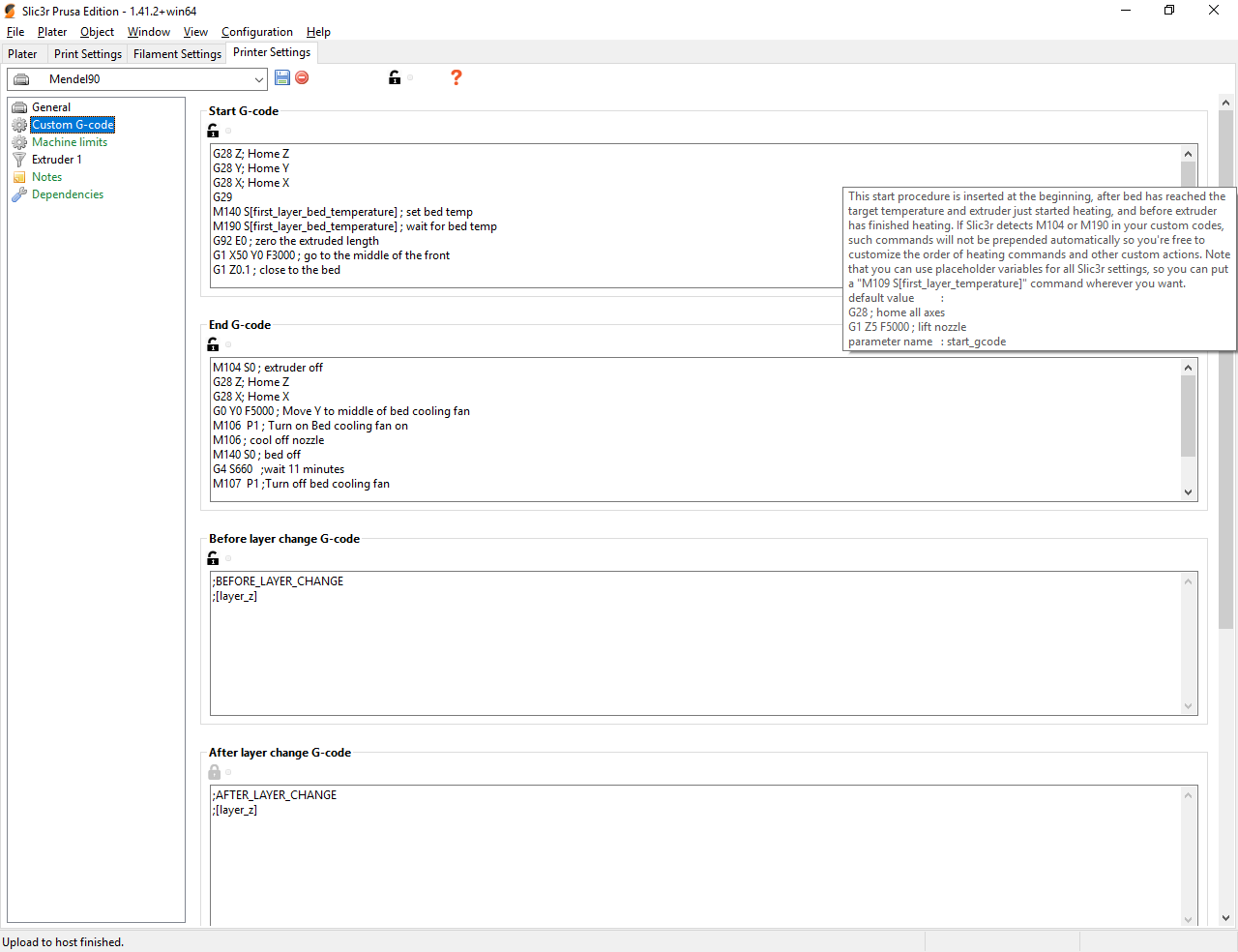
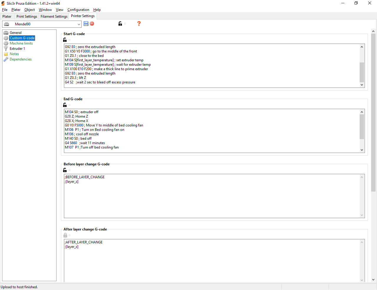
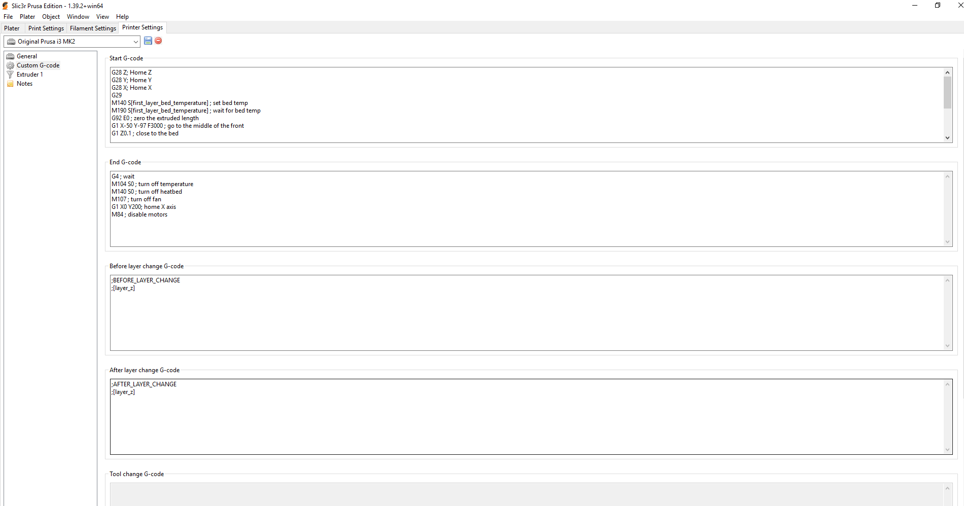
my start code from slic3r:
G28 Z; Home Z
G28 Y; Home Y
G28 X; Home X
G29
M140 S[first_layer_bed_temperature] ; set bed temp
M190 S[first_layer_bed_temperature] ; wait for bed temp
G92 E0 ; zero the extruded length
G1 X50 Y0 F3000 ; go to the middle of the front
G1 Z0.1 ; close to the bed
M104 S[first_layer_temperature] ; set extruder temp
M109 S[first_layer_temperature] ; wait for extruder temp
G1 X100 E10 F200 ; make a thick line to prime extruder
G92 E0 ; zero the extruded length
G1 Z0.3 ; lift Z
G4 S2   ;wait 2 sec to bleed off excess pressure
endcode:
M104 S0 ; extruder off
G28 Z; Home Z
G28 X; Home X
G0 Y0 F5000 ; Move Y to middle of bed cooling fan
M106  P1 ; Turn on Bed cooling fan on
M106 ; cool off nozzle
M140 S0 ; bed off
G4 S660   ;wait 11 minutes
M107  P1 ;Turn off bed cooling fan
M107 ; carriage fan off
G28 Y; home Y
M84 ; disable motors
when i get back i will need to find out what should be when it says [first_layer_bed_temperature] its not the same in cura, and there are other lines that need changes
boelle
on 19 Jan 2019
ok
mpm1396
on 19 Jan 2019
I just reinstalled cura and this is the start gcode it comes with:
G21 ;metric values
G90 ;absolute positioning
M82 ;set extruder to absolute mode
M107 ;start with the fan off
G28 X0 Y0 ;move X/Y to min endstops
G28 Z0 ;move Z to min endstops
G1 Z15.0 F{travel_speed} ;move the platform down 15mm
G92 E0 ;zero the extruded length
G1 F200 E3 ;extrude 3mm of feed stock
G92 E0 ;zero the extruded length again
G1 F{travel_speed}
;Put printing message on LCD screen
M117 Printing...
mpm1396
on 19 Jan 2019
short break before desert... yes you can use slic3r.... i can help you with that as i use it too
but back in an hour
boelle
on 19 Jan 2019
ok
mpm1396
on 19 Jan 2019
My start code adjusted for cura an your printer
G28 Z; Home Z
G28 Y; Home Y
G28 X; Home X
G29
M140 S{print_bed_temperature} ; set bed temp
M190 S{print_bed_temperature} ; wait for bed temp
G92 E0 ; zero the extruded length
G1 X-50 Y-97 F3000 ; go to the middle of the front
G1 Z0.1 ; close to the bed
M104 S{print_temperature}; set extruder temp
M109 S{print_temperature}; wait for extruder temp
G1 X0 E10 F200 ; make a thick line to prime extruder
G92 E0 ; zero the extruded length
G1 Z0.3 ; lift Z
G4 S2   ;wait 2 sec to bleed off excess pressure
stop code
M104 S0 ; extruder off
G28 X; Home X
G28 Y; home Y
M84 ; disable motors
back in 20 mins and we can have a look at slic3r if you want
boelle
on 19 Jan 2019
about slic3r PE
get it here: https://www.prusa3d.com/drivers/drivers-changelog/#mk25
V2.1.6 to start with, when its starting up it will ask you which printer to install, pick mk2.5 with 0.4 mm nozzle
all you nedd after its starts up next is to adjust start and stop gcode
and you have my start code gcode, but it needs adjustment for your printer
G28 Z; Home Z
G28 Y; Home Y
G28 X; Home X
G29
M140 S[first_layer_bed_temperature] ; set bed temp
M190 S[first_layer_bed_temperature] ; wait for bed temp
G92 E0 ; zero the extruded length
G1 X-50 Y-97 F3000 ; go to the middle of the front
G1 Z0.1 ; close to the bed
M104 S[first_layer_temperature] ; set extruder temp
M109 S[first_layer_temperature] ; wait for extruder temp
G1 X0 E10 F200 ; make a thick line to prime extruder
G92 E0 ; zero the extruded length
G1 Z0.3 ; lift Z
G4 S2   ;wait 2 sec to bleed off excess pressure
stop code
M104 S0 ; extruder off
G28 X; Home X
G28 Y; home Y
M84 ; disable motors
Ok i am Back. I will try both in a few minutes
mpm1396
on 20 Jan 2019
I tried your cura start gcode, it seems good but 1) it doesnt do a bed Level and 2) the nozzle is to close to the bed a bit
What values to Change?
mpm1396
on 20 Jan 2019
hi, just got out of bed so i will need to have breakfast first
but value to change is
define Z_PROBE_OFFSET_FROM_EXTRUDER -0.4
try and change it to
define Z_PROBE_OFFSET_FROM_EXTRUDER -0.3
upload
M502
M500
try test print again
will have to think about bed level, its in start code, look for G29
could you attach configuration.h and configuration_adv.h in a zip file?
boelle
on 20 Jan 2019
Configuration.zip
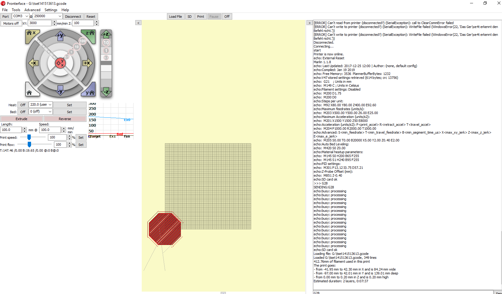
besides the Problems from above it does some wierd Things.
It crashes in the x axxis on the opposite site of the endstop for a second. It prints the Pentagon shape for a while but then it prints on a single line.
mpm1396
on 20 Jan 2019
and it moves Pretty wierd. I ll try to make a video
mpm1396
on 20 Jan 2019
oki, i will start to look through the config files to see if we missed anything
boelle
on 20 Jan 2019
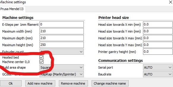
ohh
is the slicer set to have 0,0 in center?
boelle
on 20 Jan 2019
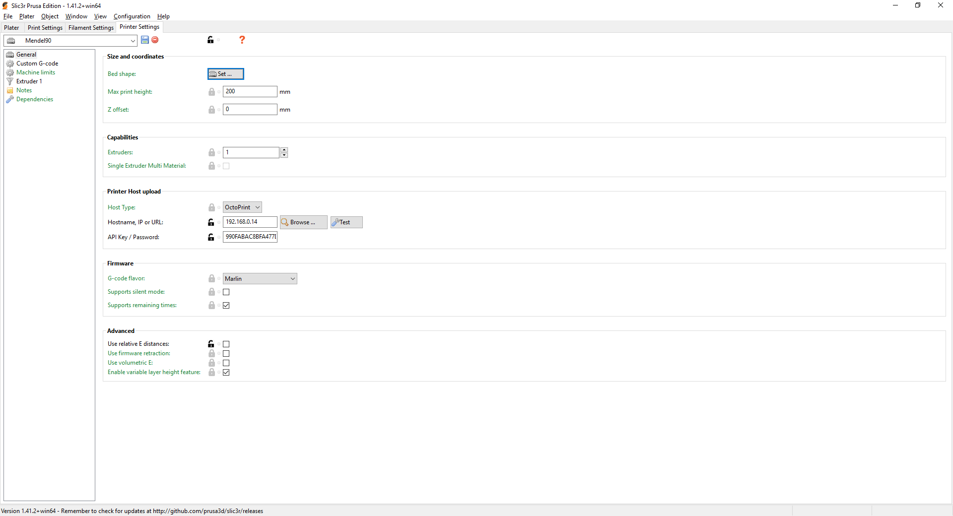
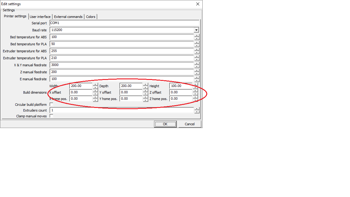
then this is the place to change it, click the botton next to bed shape
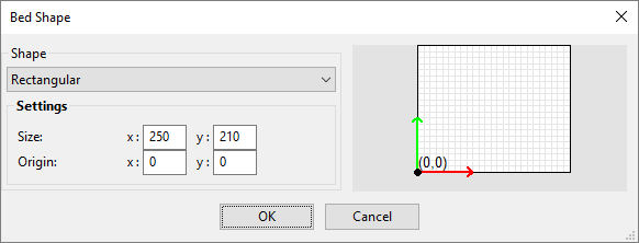
enter 105 in both box's for bed origin, you see different numbers for bed shape as i use a different bed
boelle
on 20 Jan 2019
yes
mpm1396
on 20 Jan 2019
quick experiment
send G28 to printer then G29 from pronterface, what happens?
boelle
on 20 Jan 2019
both from pronterface? first G28 then G29?
mpm1396
on 20 Jan 2019
yes
boelle
on 20 Jan 2019
G29 should make it probe the bed, if it does not we need help finding out
boelle
on 20 Jan 2019
G29 does probe the bed it Looks good. G28 homes X and Y and Z one time. But on G28 the bltouch gets triggered to late and the nozzle touches the bed too much.
mpm1396
on 20 Jan 2019
so the pin in bltouch does not come out in good time before it hits bed?
boelle
on 20 Jan 2019
I am not shure why but I just repeated the testprint and now it does probe the but
mpm1396
on 20 Jan 2019
so the pin in bltouch does not come out in good time before it hits bed?
no the pin is down but it gets triggered to late, but only on G28
mpm1396
on 20 Jan 2019
I am not shure why but I just repeated the testprint and now it does probe the but
now its heating let me see whats coming next.
mpm1396
on 20 Jan 2019
strange, maybe @Roxy-3D know what is going on, ie why the probe is triggered to late
maybe we need to enable some extra debug output so we can get more details on what is going on
boelle
on 20 Jan 2019
when I try to print it again without pronterface connected it sais G28 Z forbidden on the LCD and it doesnt probe
mpm1396
on 20 Jan 2019
anyone that follows this: config is here: https://github.com/MarlinFirmware/Marlin/issues/12948#issuecomment-455856838
boelle
on 20 Jan 2019
but does it print when you do it from pc? just so we know if it makes any difference
boelle
on 20 Jan 2019
are you kidding me now G28 is just fine. What is this?
mpm1396
on 20 Jan 2019
but does it print when you do it from pc? just so we know if it makes any difference
wait I ll try it with pronterface
mpm1396
on 20 Jan 2019
https://github.com/MarlinFirmware/Marlin/issues/5824
so i think it has something to do with same homing...
what it means is that you are to close to the bed when you try G28
boelle
on 20 Jan 2019
is this normal?
mpm1396
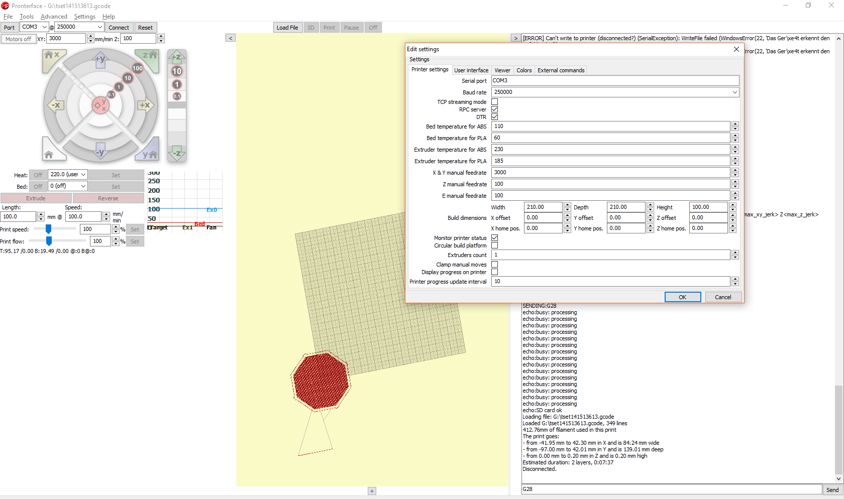
on 20 Jan 2019
no, pronterface thinks 0,0 is in the corner
i will look where to change that
boelle
on 20 Jan 2019
The nozzle pushed down the bed a bit. But now G28 is fine
mpm1396
on 20 Jan 2019
no, pronterface things 0,0 is in the corner
ok wait i ll print it trough cura
mpm1396
on 20 Jan 2019
boelle
on 20 Jan 2019
I tried it with cura and it said on the LCD: G28 Z forbidden and then home Z first
I ll Change the Settings and try it with pronterface
mpm1396
on 20 Jan 2019
mpm1396
on 20 Jan 2019
So we need to change start code a bit to make it happen
but lets get pronterface correct also, trying to figure out what of the 2 last lines to change
boelle
on 20 Jan 2019
are you opening the gcode from cura in pronterface?
boelle
on 20 Jan 2019
yes the gcode I was trying to print before
mpm1396
on 20 Jan 2019
oki, dont worrie, i'm just slow to find out things
boelle
on 20 Jan 2019
here is the gcode
gcode used.zip
mpm1396
on 20 Jan 2019
cura still thinks 0,0 is down the corner i think
have you tried slic3r pe?
boelle
on 20 Jan 2019
Wait i ll try it. Which start gcode?
mpm1396
on 20 Jan 2019
the one i have posted last night
boelle
on 20 Jan 2019
boelle
on 20 Jan 2019
ok its downloading. But is my bed like the prusa mk2.5?
mpm1396
on 20 Jan 2019
nope, but it does not matter
how to set 0,0 in center: https://github.com/MarlinFirmware/Marlin/issues/12948#issuecomment-455857670
boelle
on 20 Jan 2019
ok wait a sec
mpm1396
on 20 Jan 2019
and in same place where you set 0,0 in center you change bed size
boelle
on 20 Jan 2019
remember V2.1.6
boelle
on 20 Jan 2019
ohh i downloaded 2.2.2. Wait ill download 2.1.6 :D
mpm1396
on 20 Jan 2019
if you are confused about the difference between slicer and pronterface here is the short explanation
slicer(cura or slic3r pe or any other program) prepares the model, so its the slicer that decides where on the bed printer is going
pronterface is just a control program that sends instructions to the printer, it does not change the gcode
why i want to test slic3r pe is because i know that program better and we can see if there is any change in the gcode when you load it in pronter face
but its sunday, lets take it easy, no reason for stress
boelle
on 20 Jan 2019
ok I tried it. It doesnt home Z and it doesnt probe the bed. So its printing in mid air.
Gcode:
testsli3r.zip
now I try this gcode through pronterface
mpm1396
on 20 Jan 2019
post picture of start code in slic3r pe
boelle
on 20 Jan 2019
first delete all gcode and then insert the one i gave last night
boelle
on 20 Jan 2019
mine looks like this, and you cant use it since you wanted 0,0 in center
boelle
on 20 Jan 2019
this is all:
G28 Z; Home Z
G28 Y; Home Y
G28 X; Home X
G29
M140 S[first_layer_bed_temperature] ; set bed temp
M190 S[first_layer_bed_temperature] ; wait for bed temp
G92 E0 ; zero the extruded length
G1 X-50 Y-97 F3000 ; go to the middle of the front
G1 Z0.1 ; close to the bed
M104 S[first_layer_temperature] ; set extruder temp
M109 S[first_layer_temperature] ; wait for extruder temp
G1 X0 E10 F200 ; make a thick line to prime extruder
G92 E0 ; zero the extruded length
G1 Z0.3 ; lift Z
G4 S2 ;wait 2 sec to bleed off excess pressure
mpm1396
on 20 Jan 2019
it said at the beginnig on the LCD: G28 Z forbidden
mpm1396
on 20 Jan 2019
this is very strange
G28 Z should home Z first
but maybe we need to change it so it homes Z last
boelle
on 20 Jan 2019
ok just change G28Z and G28X ?
mpm1396
on 20 Jan 2019
why is it forbidden?
mpm1396
on 20 Jan 2019
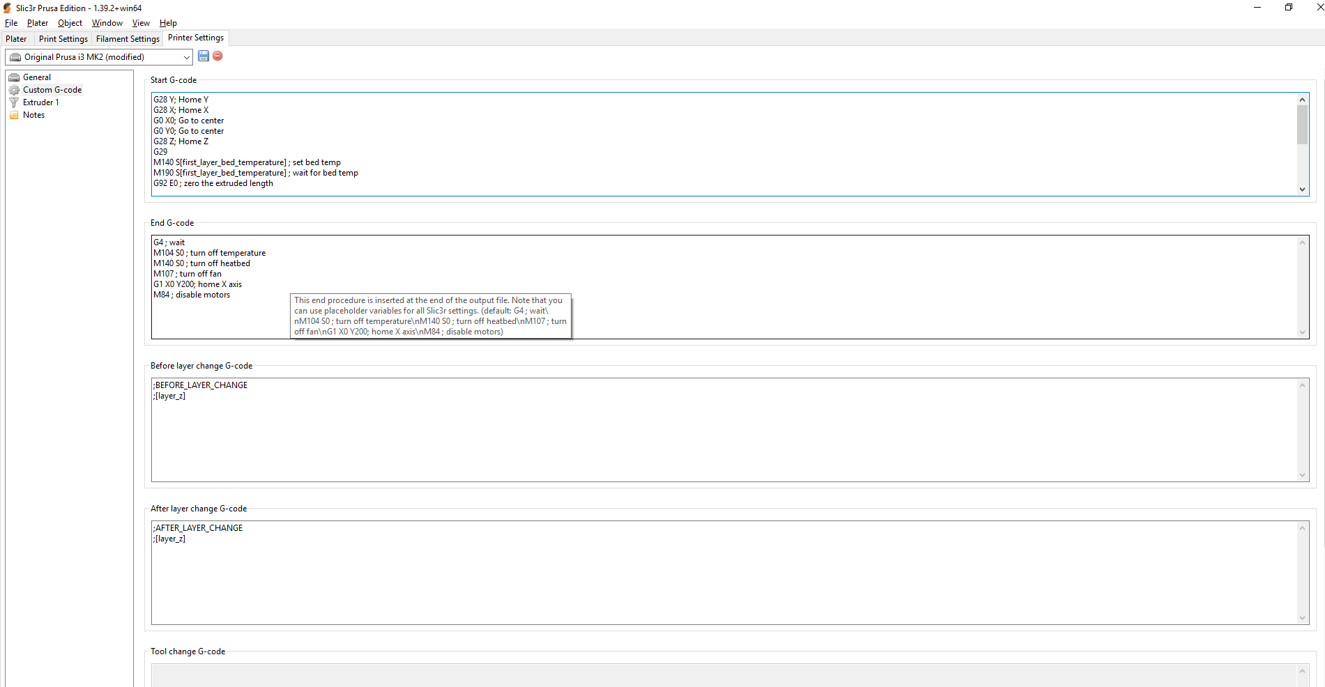
G28 Y; Home Y
G28 X; Home X
G0 X0; Go to center
G0 Y0; Go to center
G28 Z; Home Z
G29
M140 S[first_layer_bed_temperature] ; set bed temp
M190 S[first_layer_bed_temperature] ; wait for bed temp
G92 E0 ; zero the extruded length
G1 X-50 Y-97 F3000 ; go to the middle of the front
G1 Z0.1 ; close to the bed
M104 S[first_layer_temperature] ; set extruder temp
M109 S[first_layer_temperature] ; wait for extruder temp
G1 X0 E10 F200 ; make a thick line to prime extruder
G92 E0 ; zero the extruded length
G1 Z0.3 ; lift Z
G4 S2 ;wait 2 sec to bleed off excess pressure
boelle
on 20 Jan 2019
its forbidden because it does not know where probe is on bed before X and Y is homed
boelle
on 20 Jan 2019
ok should I switch G28 Z and X
mpm1396
on 20 Jan 2019
i have changed the code so it now homes X and Y and then goes to center before it homes Z
boelle
on 20 Jan 2019
ok
mpm1396
on 20 Jan 2019
no use the code i just gave you.... see the changes?
boelle
on 20 Jan 2019
brb, need to start a print
boelle
on 20 Jan 2019
no dont see changes
mpm1396
on 20 Jan 2019
before:
G28 Z; Home Z
G28 Y; Home Y
G28 X; Home X
G29
after:
G28 Y; Home Y
G28 X; Home X
G0 X0; Go to center
G0 Y0; Go to center
G28 Z; Home Z
G29
boelle
on 20 Jan 2019
see it now?
boelle
on 20 Jan 2019
nah but I ll copy this
mpm1396
on 20 Jan 2019
stop
you need to understand it or else you dont know what is going on
boelle
on 20 Jan 2019
all:
G28 Y; Home Y
G28 X; Home X
G0 X0; Go to center
G0 Y0; Go to center
G28 Z; Home Z
G29
M140 S[first_layer_bed_temperature] ; set bed temp
M190 S[first_layer_bed_temperature] ; wait for bed temp
G92 E0 ; zero the extruded length
G1 X-50 Y-97 F3000 ; go to the middle of the front
G1 Z0.1 ; close to the bed
M104 S[first_layer_temperature] ; set extruder temp
M109 S[first_layer_temperature] ; wait for extruder temp
G1 X0 E10 F200 ; make a thick line to prime extruder
G92 E0 ; zero the extruded length
G1 Z0.3 ; lift Z
G4 S2 ;wait 2 sec to bleed off excess pressure
mpm1396
on 20 Jan 2019
before the first bit of the start code was:
G28 Z; Home Z
G28 Y; Home Y
G28 X; Home X
G29
now its
G28 Y; Home Y
G28 X; Home X
G0 X0; Go to center
G0 Y0; Go to center
G28 Z; Home Z
G29
i moved home Z down just before G29
and after home of Y and X asked the nozzle to go to center of bed
boelle
on 20 Jan 2019
before:
G28 Z; Home Z
G28 Y; Home Y
G28 X; Home X
G29after:
G28 Y; Home Y
G28 X; Home X
G0 X0; Go to center
G0 Y0; Go to center
G28 Z; Home Z
G29
here I can see it but in your post from last night I do not see any changes
mpm1396
on 20 Jan 2019
you got it right in slic3r pe
boelle
on 20 Jan 2019
no these changes was not there last night because i did not know of the forbidden error
we have now changed it so it should not give this error
boelle
on 20 Jan 2019
i ll try it wait
mpm1396
on 20 Jan 2019
how does bed setup look like?

boelle
on 20 Jan 2019
i have another bed remember that
your number should be
210 210
105 105
boelle
on 20 Jan 2019
yes they are
mpm1396
on 20 Jan 2019
now it homes z fine and probes the bed fine. But it still does wierd Things. it s
newtestsli3r.zip
ill crashes for a sec in the x axis oposite side of the endstop. and it doesnt make that Pentagon shape. I ll capture a video
mpm1396
on 20 Jan 2019
i think what is giving us so much pain is that you want 0,0 in center
can we have 0,0 in lower left corner instead?
boelle
on 20 Jan 2019
of course. i dont want 0,0 in center :D
mpm1396
on 20 Jan 2019
i thought you wanted that :-D but oh well it's easy to change let me look through config
boelle
on 20 Jan 2019
define BED_CENTER_AT_0_0
change to
//#define BED_CENTER_AT_0_0
define LEFT_PROBE_BED_POSITION -25
define RIGHT_PROBE_BED_POSITION 100
define FRONT_PROBE_BED_POSITION -93
define BACK_PROBE_BED_POSITION 100
change to
define LEFT_PROBE_BED_POSITION 25
define RIGHT_PROBE_BED_POSITION 100
define FRONT_PROBE_BED_POSITION 93
define BACK_PROBE_BED_POSITION 100
define X_MIN_POS -109
define Y_MIN_POS -107
define Z_MIN_POS 0
define X_MAX_POS 105
define Y_MAX_POS 105
define Z_MAX_POS 250
change to
define X_MIN_POS 109
define Y_MIN_POS 107
define Z_MIN_POS 0
define X_MAX_POS 105
define Y_MAX_POS 105
define Z_MAX_POS 250
try and compile and see if error free (should be)
boelle
on 20 Jan 2019
upps....
define X_MIN_POS 0
define Y_MIN_POS 0
define Z_MIN_POS 0
define X_MAX_POS 210
define Y_MAX_POS 210
define Z_MAX_POS 250
boelle
on 20 Jan 2019
erro :D static assertion failed: LEFT_PROBE_BED_POSITION can't be reached by the Z probe.
mpm1396
on 20 Jan 2019
define X_MIN_POS 0
define Y_MIN_POS 0
define Z_MIN_POS 0
define X_MAX_POS 210
define Y_MAX_POS 210
define Z_MAX_POS 250
define LEFT_PROBE_BED_POSITION 25
define RIGHT_PROBE_BED_POSITION 100
define FRONT_PROBE_BED_POSITION 93
define BACK_PROBE_BED_POSITION 100
//#define BED_CENTER_AT_0_0
mpm1396
on 20 Jan 2019
define LEFT_PROBE_BED_POSITION 75
define RIGHT_PROBE_BED_POSITION 210
define FRONT_PROBE_BED_POSITION 93
define BACK_PROBE_BED_POSITION 210
try that
boelle
on 20 Jan 2019
i guess next is error on front :-D
boelle
on 20 Jan 2019
no it compiles fine. I uploaded it
mpm1396
on 20 Jan 2019
whats next?
mpm1396
on 20 Jan 2019
define FRONT_PROBE_BED_POSITION 7
define BACK_PROBE_BED_POSITION 210
still without error?
boelle
on 20 Jan 2019
this works_:
define FRONT_PROBE_BED_POSITION 93
define BACK_PROBE_BED_POSITION 210
this aswell
define FRONT_PROBE_BED_POSITION 7
define BACK_PROBE_BED_POSITION 210
mpm1396
on 20 Jan 2019
go with the last
define FRONT_PROBE_BED_POSITION 93
define BACK_PROBE_BED_POSITION 210
upload
then M502
then M500
then we are sure it uses latest settings
boelle
on 20 Jan 2019
then send one line at a time
G28 Y
G28 X
G0 X0
G0 Y0
G28 Z
G29
boelle
on 20 Jan 2019
this works
G28 Y
G28 X
G0 X0 --> bed runs in endstop
mpm1396
on 20 Jan 2019
upppps again
boelle
on 20 Jan 2019
G28 Y
G28 X
G0 X105
G0 Y105
G28 Z
G29
we also need to change start code latyer
boelle
on 20 Jan 2019
G0 X105 --> still running in bed endstop
mpm1396
on 20 Jan 2019
did you do G28 X first?
boelle
on 20 Jan 2019
yes
mpm1396
on 20 Jan 2019
i ll do it again
mpm1396
on 20 Jan 2019
send config as zip again... something is wrong with config if it goes in to endstop
boelle
on 20 Jan 2019
mpm1396
on 20 Jan 2019
looks correct
send G28 X
then G28 Y
send M114
what does it say?
boelle
on 20 Jan 2019
X:0.00 Y:0.00 Z:10.00 E:0.00 Count X:0 Y:0 Z:4000
mpm1396
on 20 Jan 2019
and nozzle is in the front left corner
mpm1396
on 20 Jan 2019
Send G0 X105
where does it move?
boelle
on 20 Jan 2019
bed runs further --> in the endstop
mpm1396
on 20 Jan 2019
bed should not move... only the nozzle
send G28 X again so we can get it back in the corner
boelle
on 20 Jan 2019
now send G0 Y105
where does it move now?
boelle
on 20 Jan 2019
again in the bed endstop
mpm1396
on 20 Jan 2019
with G28 the nozzle homes
mpm1396
on 20 Jan 2019
there is something serious wrong
did the bed or nozzle move?
boelle
on 20 Jan 2019
with G28 X the nozzle
with G0 Y105 the bed
mpm1396
on 20 Jan 2019
oki, send G28 so its in the corner
boelle
on 20 Jan 2019
let me know when that is done
boelle
on 20 Jan 2019
with G28 it homes all axis after z home the nozzle stays not in the Corner but on the left side
mpm1396
on 20 Jan 2019
now send: G0 X10
nozzle should move 10mm away from endstop
boelle
on 20 Jan 2019
is X endstop in left side?
boelle
on 20 Jan 2019
no bed runs in endstop again with G0 X10
mpm1396
on 20 Jan 2019
yes x endstop is on the left side of the Extruder
mpm1396
on 20 Jan 2019
bed should not move, only nozzle
boelle
on 20 Jan 2019
yes but it does move :(
mpm1396
on 20 Jan 2019
we need to check connections... but lets take it slowly
first send M84, this will stop the steppers
next move bed and nozzle with your hand slowly away from endstops so we can get to them with finger
boelle
on 20 Jan 2019
if go on the LCD to prepare move axis and move X axxis it mooves the nozzle
mpm1396
on 20 Jan 2019
ok I mooved it away
mpm1396
on 20 Jan 2019
have you done as i told? brb, need to make coffee
boelle
on 20 Jan 2019
yes bed and nozzle is on the opposite side of the endstops now
mpm1396
on 20 Jan 2019
Send M119, what does it say?
boelle
on 20 Jan 2019
x_min: open
y_min: open
z_min: open
mpm1396
on 20 Jan 2019
now with finger press x endstop and send M119 again
boelle
on 20 Jan 2019
x_min: TRIGGERED
y_min: open
z_min: open
mpm1396
on 20 Jan 2019
when I press on bed endstop:
x_min: open
y_min: TRIGGERED
z_min: open
mpm1396
on 20 Jan 2019
then endstops are connected right
send G28 again so we have it in the corner and machine thinks its in the corner
then send M84 and move nozle and bed so its in center
boelle
on 20 Jan 2019
ok wait with G28 its not in the corner
mpm1396
on 20 Jan 2019
it moves to the Corner then it moves a bit in the Center and the home Z with the bltouch
mpm1396
on 20 Jan 2019
yes... it moves to center so its sure that probe is over bed
boelle
on 20 Jan 2019
just send G28 and then M84
boelle
on 20 Jan 2019
ok
mpm1396
on 20 Jan 2019
then with hand move bed and nozzle so its in center
boelle
on 20 Jan 2019
now machine does still think its in corner
send G0 X10, now what does move and in what direction
boelle
on 20 Jan 2019
bed runs in endstop again
mpm1396
on 20 Jan 2019
it should only move 10mm
boelle
on 20 Jan 2019
strange
mpm1396
on 20 Jan 2019
Why can I move the bed with the LCD just fine?
mpm1396
on 20 Jan 2019
but it was the bed that moved and not the nozzle?
boelle
on 20 Jan 2019
Yes the nozzle stands still
mpm1396
on 20 Jan 2019
we are not moving the bed right now, so if you move X on lcd and bed moves motors are connected wrong
boelle
on 20 Jan 2019
if I moove X it mooves the nozzle
if I move Y it moves the bed
mpm1396
on 20 Jan 2019
now i'm confused
we send G0 X10 and you say the bed moves.... X is not the bed
boelle
on 20 Jan 2019
Yes :/
with G0 X10 the bed moves in the endstop
mpm1396
on 20 Jan 2019
and that is wrong... it should be nozzle moving and not bed and it should only move 10mm
boelle
on 20 Jan 2019
Yes I know but it doesnt do it :/
mpm1396
on 20 Jan 2019
how is this possible
mpm1396
on 20 Jan 2019
Configuration_adv.zip
thats the latest config
mpm1396
on 20 Jan 2019
send G28, then M84, move it with hand to center
now send G0 Y10, does the bed or nozzle move?
boelle
on 20 Jan 2019
bed and again in the endstop
mpm1396
on 20 Jan 2019
so if we ask it to move X it moves Y
if we ask it to move Y it moves Y
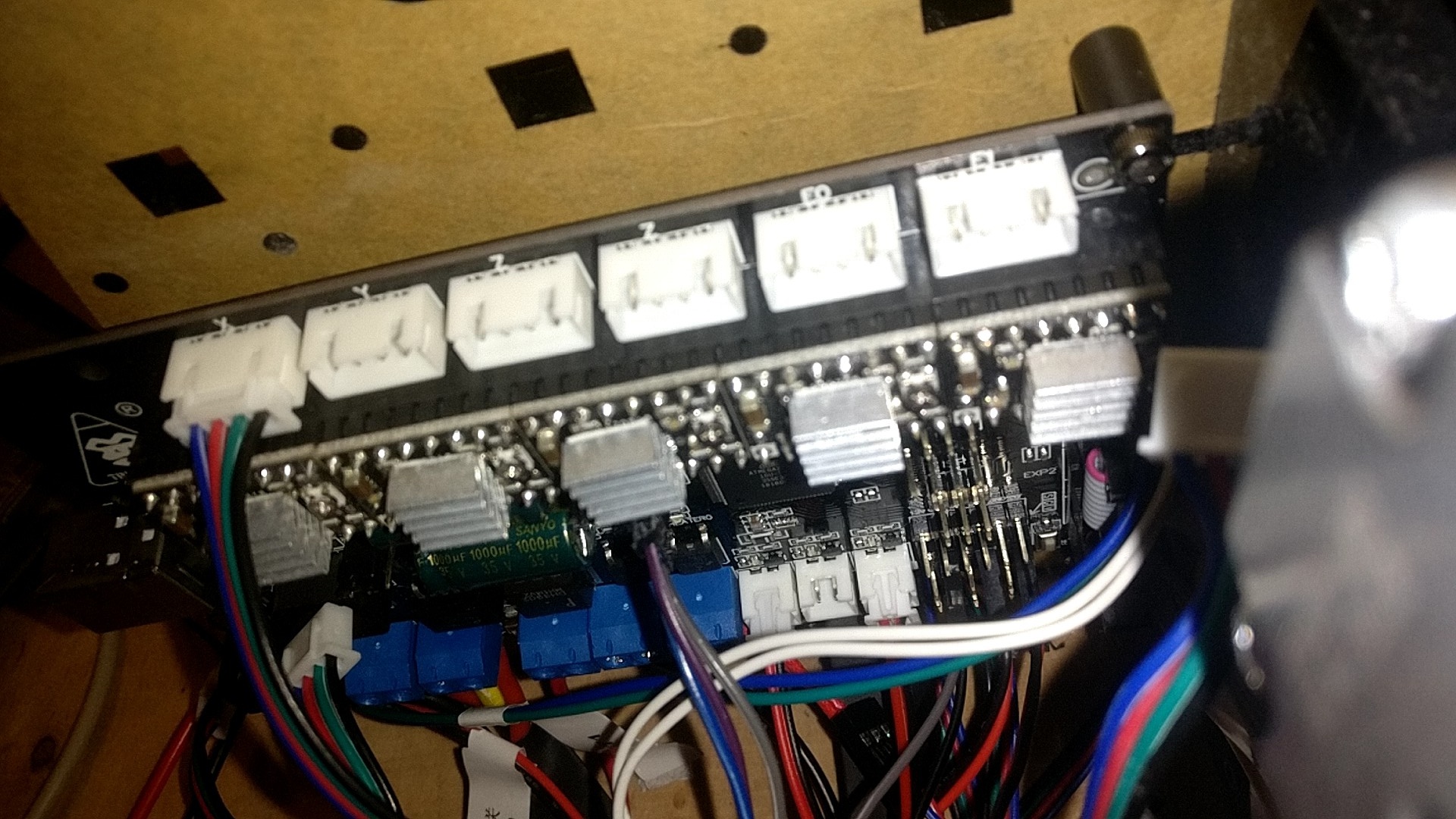
are there 2 motors connected in Y plug on electronics board?
boelle
on 20 Jan 2019
mpm1396
on 20 Jan 2019
the last picture
mpm1396
on 20 Jan 2019
I send all commands with pronterface should I try sending them with Arduino ide ?
mpm1396
on 20 Jan 2019
no
i'm thinking
boelle
on 20 Jan 2019
one of your links from yesterday, https://github.com/duisenberg/AnyCubic-I3/blob/master/Firmware/Marlin_1.1.5/Configuration.h
one difference is this line
define MOTHERBOARD BOARD_RAMPS_13_EFB
your is #define MOTHERBOARD BOARD_RAMPS_14_EFB
boelle
on 20 Jan 2019
ok
mpm1396
on 20 Jan 2019
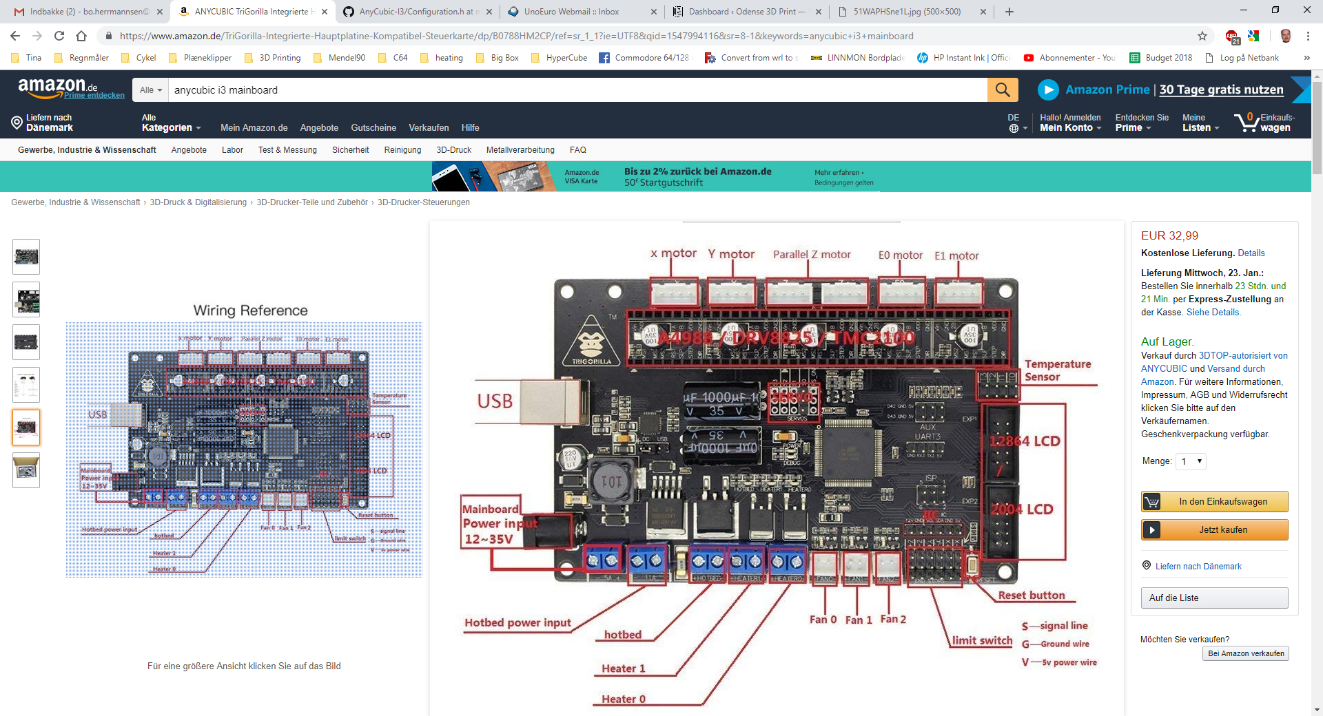
this is my mainboard: https://www.amazon.de/TriGorilla-Integrierte-Hauptplatine-Kompatibel-Steuerkarte/dp/B0788HM2CP/ref=sr_1_1?ie=UTF8&qid=1547994116&sr=8-1&keywords=anycubic+i3+mainboard
Because I blew up the old one :/
mpm1396
on 20 Jan 2019
but this happened half a year ago
mpm1396
on 20 Jan 2019
boelle
on 20 Jan 2019
sure motors are connected correct?
the pictures are not the same
boelle
on 20 Jan 2019
no they are connected like this:
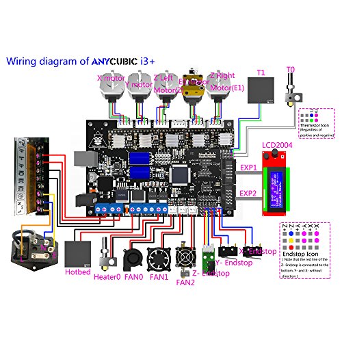
mpm1396
on 20 Jan 2019
that is not the same
boelle
on 20 Jan 2019
yes should I connect it like your picture?
mpm1396
on 20 Jan 2019
but X and Y are the same
mpm1396
on 20 Jan 2019
3 first motors are the same, but not the rest
power off electronics, you must never take out a motor with power on
takke off all steppers but leave X connected... and make sure that it is X connected and not Y
could you take a picture and post it?
boelle
on 20 Jan 2019
we need to check this very close and find out why it moves Y when we tell it to move X
boelle
on 20 Jan 2019
mpm1396
on 20 Jan 2019
now power up again
make sure Z is a little up from bed so it does not crash, you can turn Z rod with your hand
send G28 X.... only Z should move
boelle
on 20 Jan 2019
upps
only X should move
boelle
on 20 Jan 2019
yes
mpm1396
on 20 Jan 2019
X does home
mpm1396
on 20 Jan 2019
send G0 X10, what happens ?
boelle
on 20 Jan 2019
nothing
mpm1396
on 20 Jan 2019
what with G0 X-10
?
boelle
on 20 Jan 2019
nothing aswell
mpm1396
on 20 Jan 2019
power down and take out X stepper driver and put in Y stepper driver where X was
we need to check that X driver is not blown
boelle
on 20 Jan 2019
waiiitt
boelle
on 20 Jan 2019
same result G28 X moves home G0 X10 nothing
mpm1396
on 20 Jan 2019
X did home fine so driver is fine, just me getting a bit desperat to find out what is wrong
boelle
on 20 Jan 2019
now power down
take X motor out and put in Y motor and now send G28 Y
boelle
on 20 Jan 2019
then send G0 Y10
boelle
on 20 Jan 2019
G28 --> bed homes fine
G0 Y10 --> bed runs in endstop
mpm1396
on 20 Jan 2019
aha.... so it moves Y in wrong direction
brb
boelle
on 20 Jan 2019
change
define INVERT_Y_DIR false
to
define INVERT_Y_DIR true
upload
boelle
on 20 Jan 2019
then G28 Y
then G0 Y10
boelle
on 20 Jan 2019
now when I do G28 Y the bed runs away from the endstop and crashes in the opposite side
mpm1396
on 20 Jan 2019
oki, so change it back
define Y_HOME_DIR -1
change to
define Y_HOME_DIR 1
upload and try again, hope it does not crash this time
boelle
on 20 Jan 2019
what i did was telling it that the endstop is in the max end
if i'm correct when we send G0 Y10 it should move away from endstop and not crash in to it
boelle
on 20 Jan 2019
error: #error "Enable USE_YMAX_PLUG when homing Y to MAX."
mpm1396
on 20 Jan 2019
change back to #define Y_HOME_DIR -1
your board does not have Y max plug
need to think very hard now
boelle
on 20 Jan 2019
ok :/
mpm1396
on 20 Jan 2019
upload firmware
then G28 Y
then G0 Y-10
2 things can happen, either Y does not move after home or it moves away from endstop
boelle
on 20 Jan 2019
wait so I upload with home dir -1 and #define INVERT_Y_DIR false
mpm1396
on 20 Jan 2019
yes
boelle
on 20 Jan 2019
with this G0 Y-10 nothing happens
mpm1396
on 20 Jan 2019
and G0 Y10 makes it go in to endstop..... very strange
boelle
on 20 Jan 2019
Yes :/
mpm1396
on 20 Jan 2019
define MOTHERBOARD BOARD_RAMPS_14_EFB
try and change to
define MOTHERBOARD BOARD_RAMPS_13_EFB
boelle
on 20 Jan 2019
it will proberly not make a difference but i just wanted to try it
boelle
on 20 Jan 2019
Yes no difference
mpm1396
on 20 Jan 2019
i have made a small list of things we have discovered so far, does the list look correct?
endstops are connected correct
X and Y homes ok
when sending G28 X followed by G0 X10 nothing happens
when sending G28 Y followed by G0 Y10 it crashes in to Y endstop
boelle
on 20 Jan 2019
change
define MOTHERBOARD BOARD_RAMPS_13_EFB
back to
define MOTHERBOARD BOARD_RAMPS_14_EFB
boelle
on 20 Jan 2019
i have made a small list of things we have discovered so far, does the list look correct?
endstops are connected correct
X and Y homes ok
when sending G28 X followed by G0 X10 nothing happens
when sending G28 Y followed by G0 Y10 it crashes in to Y endstop
yes
mpm1396
on 20 Jan 2019
now power down and connect X so we have both X and Y connected
how many Z motors ? 1 or 2 ?
boelle
on 20 Jan 2019
2 Z motors
mpm1396
on 20 Jan 2019
connect both of them in to Z stepper connectors(2 middle plugs)
boelle
on 20 Jan 2019
power up
send G28 and it should home fine
boelle
on 20 Jan 2019
then send Go Z10... if it works it should move Z up 10mm
boelle
on 20 Jan 2019
G0 not Go
boelle
on 20 Jan 2019
ok
mpm1396
on 20 Jan 2019
when I do G28 it seems fine but I think only one Z Motor is moving
mpm1396
on 20 Jan 2019
strange
power down and move one Z motor to E1
and then try again
boelle
on 20 Jan 2019
i just read the adv config file and it uses 2 stepper drivers so that is why only of them moved i think
boelle
on 20 Jan 2019
what if I send G0 Z10 it moves the bed aswell
mpm1396
on 20 Jan 2019
it should not move Y (bed)
boelle
on 20 Jan 2019
Yes I know :?
mpm1396
on 20 Jan 2019
and I am still not understanding why with the LCD I can move every axis just fine :D
mpm1396
on 20 Jan 2019
but did Z move up? and what direction did the bed move?
boelle
on 20 Jan 2019
when i do G0 Z10 it only moves the bed in the endstop again
mpm1396
on 20 Jan 2019
Z did not move at all?
boelle
on 20 Jan 2019
So this means for
G0 Z10
G0 X10
G0 Y10
it Always movbes the bed in the endstop
mpm1396
on 20 Jan 2019
what if I send G0 Z10 it moves the bed aswell
when you say that it suggest that both Z and Y moves
boelle
on 20 Jan 2019
no Z doesnt move at all
mpm1396
on 20 Jan 2019
for
G0 Z10
G0 X10
G0 Y10
it Always moves the bed and only the bed in the endstop
mpm1396
on 20 Jan 2019
new list then
endstops are connected correct
X and Y homes ok
when sending G28 X followed by G0 X10 nothing happens
when sending G28 Y followed by G0 Y10 it crashes in to Y endstop
checked that both X and Y steppers are not blown
when sending G28 Z followed by G0 Z10 Z does not move and bed crash in to endstop
when homing and moving from the lcd everything works fine
boelle
on 20 Jan 2019
i'm starting to think that its an error in firmware, where did you get it from?
boelle
on 20 Jan 2019
i'm starting to think that its an error in firmware, where did you get it from?
from https://github.com/MarlinFirmware/Marlin/archive/1.1.8.zip
mpm1396
on 20 Jan 2019
then it should be ok
this is very strange but we have narrowed things down, not sure if it helps creating a new issue and close this one
i was thinking about calling a new issue something like: Anycubic I3 homes fine but crash's Y endstop on any move with X and Y
then in new issue use the list i have made
reason for doing this is to make issue shorter and show people what we have tested so far
boelle
on 20 Jan 2019
sorry for chiming in
@mpm1396 is using a Trigorilla board, this board has its own board definition in marlin
and the E1 driver pins get undefined, so they are not usable in marlin
you should probably use only one z driver for both z motors
 kAdonis
on 20 Jan 2019
kAdonis
on 20 Jan 2019
ok so what do I have to do now?
mpm1396
on 20 Jan 2019
what is the board deff then? i tried to look for an anycubic config file but there are none
boelle
on 20 Jan 2019
using the wrong board would explain a bit :-D
boelle
on 20 Jan 2019
the trigorialla board is just a Arduino mega and a ramps or am I wrong?
mpm1396
on 20 Jan 2019
pins_TRIGORILLA_13.h or pins_TRIGORILLA_14.h
boelle
on 20 Jan 2019
define MOTHERBOARD BOARD_TRIGORILLA_13 or #define MOTHERBOARD BOARD_TRIGORILLA_14
boelle
on 20 Jan 2019
ok and the rest the same?
mpm1396
on 20 Jan 2019
board can be basicly the same, but sometimes people say its just a ramps and mega in one board
but they forget that sometimes the maker changes the pins used..
boelle
on 20 Jan 2019
yes just change
define MOTHERBOARD BOARD_RAMPS_14_EFB
to
define MOTHERBOARD BOARD_TRIGORILLA_14
boelle
on 20 Jan 2019
error "Unknown MOTHERBOARD value set in Configuration.h"
mpm1396
on 20 Jan 2019
when/if we get this working we should upload the config so that others dont have to search for it
anycubic have not put anything on their site, not even the firmware, so they break the license :-(
only thing they have put up is a hex file, not the source as they should
but if we upload the config we can help others
boelle
on 20 Jan 2019
let me find the right board name
boelle
on 20 Jan 2019
ok
mpm1396
on 20 Jan 2019
why has he:
https://github.com/duisenberg/AnyCubic-I3/blob/master/Firmware/Marlin_1.1.5/Configuration.h
the ramps 13 as Motherboard defined?
mpm1396
on 20 Jan 2019
boelle
on 20 Jan 2019
i dont know why he has. its not main marlin anyway
boelle
on 20 Jan 2019
so what #define MOTHERBOARD now?
mpm1396
on 20 Jan 2019
oops, the board is not in marlin 1.1.8 its in 1.1.9
kAdonis
on 20 Jan 2019
so download marlin 1.1.9 then?
mpm1396
on 20 Jan 2019
@kAdonis but did i get the define correct?
boelle
on 20 Jan 2019
@mpm1396 i think its better to go for 2.0, maybe
boelle
on 20 Jan 2019
isnt marlin 2.0 in alpha or so. I mean for me it doesnt matter as long as we can get it to work
mpm1396
on 20 Jan 2019
i use it.... no problems here
boelle
on 20 Jan 2019
ok so just download it and copy config and config adv?
mpm1396
on 20 Jan 2019
no you need to compare new and old config and move over settings
i can do it for you
can you post config as they are precise now, both files
boelle
on 20 Jan 2019
Configuration.zip
Thank you so much :)
mpm1396
on 20 Jan 2019
@boelle Yes
BOARD_TRIGORILLA_14 or BOARD_TRIGORILLA_13
I can't tell from the picture, I dont use the board
I also recommend marlin 2.0
in BOARD_TRIGORILLA_13 E1 is undefined!
kAdonis
on 20 Jan 2019
@kAdonis its this board: https://www.amazon.de/TriGorilla-Integrierte-Hauptplatine-Kompatibel-Steuerkarte/dp/B0788HM2CP/ref=sr_1_1?ie=UTF8&qid=1548000760&sr=8-1&keywords=anycubic+i3+mainboard
i think its the _14
mpm1396
on 20 Jan 2019
oki... we will get it
doing the work looks like this
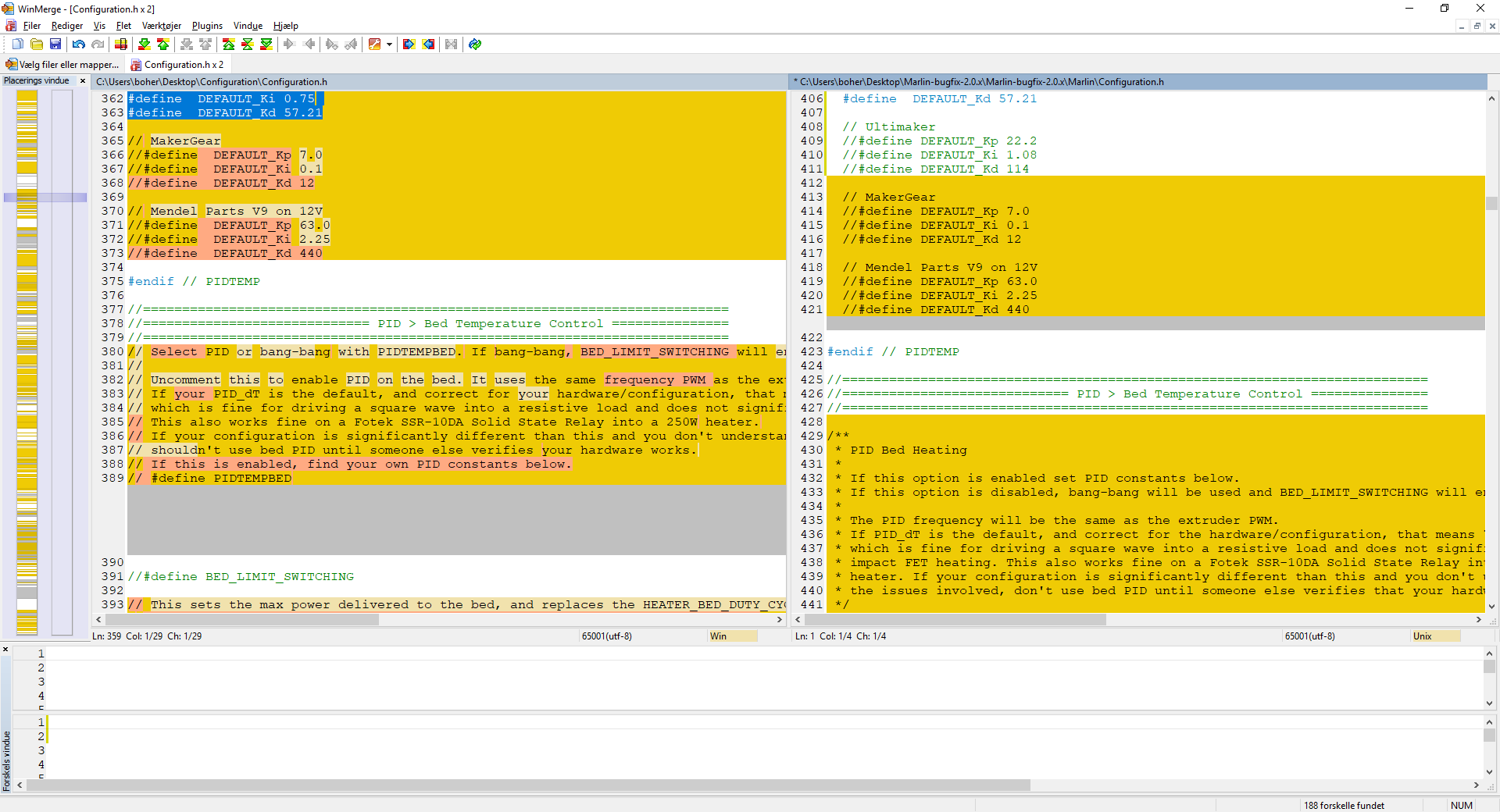
old config on left, new on right
boelle
on 20 Jan 2019
sorry, I dont know
ich kenne das Board auch nur vom Foto
kAdonis
on 20 Jan 2019
ok then we have to try it i guess
mpm1396
on 20 Jan 2019
und ich bin nur ein dumme däne 👍
boelle
on 20 Jan 2019
i like Denmark
mpm1396
on 20 Jan 2019
configuration.h: https://pastebin.com/PGyUWRA0
need to do the configuration_adv.h also
boelle
on 20 Jan 2019
configuration_adv.h: https://pastebin.com/8vKqBbbF
but dinner time to so have to go for 1-2 hours
boelle
on 20 Jan 2019
what areduino ide do you use?
boelle
on 20 Jan 2019
what areduino ide do you use?
1.8.8
mpm1396
on 20 Jan 2019
Oki. Still not back. Did it compile?
søn. 20. jan. 2019 17.53 skrev mpm1396 notifications@github.com:
what areduino ide do you use?1.8.8 from Windows store
—
You are receiving this because you were mentioned.
Reply to this email directly, view it on GitHub
https://github.com/MarlinFirmware/Marlin/issues/12948#issuecomment-455882661,
or mute the thread
https://github.com/notifications/unsubscribe-auth/ADp5r9L-6NqSROIMDtq99UzOQWjmpFC_ks5vFJ8LgaJpZM4aIkpm
.
boelle
on 20 Jan 2019
I am not sure how to install 2.0 . I downloaded it from: https://github.com/MarlinFirmware/Marlin/archive/bugfix-2.0.x.zip
but where do I have to paste my configs?
mpm1396
on 20 Jan 2019
Or how is this working because in the marlin folder there is now only config, config adv, makefile, and marlin.ino and two folders
mpm1396
on 20 Jan 2019
paste config from the 2 links i posted in to marlin folder where you only see marlin.ino and 2 folders
then open marlin.ino in arduino ide
boelle
on 20 Jan 2019
ok so it is normal that there are only 3 tabs in the Arduino ide now?
mpm1396
on 20 Jan 2019
ok its uploaded now whats next?
mpm1396
on 20 Jan 2019
Yes they have cleaned up marlin and made it more simple
søn. 20. jan. 2019 18.37 skrev mpm1396 notifications@github.com:
ok so it is normal that there are only 3 tabs in the Arduino ide now?
—
You are receiving this because you were mentioned.
Reply to this email directly, view it on GitHub
https://github.com/MarlinFirmware/Marlin/issues/12948#issuecomment-455886003,
or mute the thread
https://github.com/notifications/unsubscribe-auth/ADp5r-Ha_zp1fPZQr_MSOOqd8IPcmtxHks5vFKl0gaJpZM4aIkpm
.
boelle
on 20 Jan 2019
Next is me coming back from dinner
søn. 20. jan. 2019 18.40 skrev mpm1396 notifications@github.com:
ok its uploaded now whats next?
—
You are receiving this because you were mentioned.
Reply to this email directly, view it on GitHub
https://github.com/MarlinFirmware/Marlin/issues/12948#issuecomment-455886134,
or mute the thread
https://github.com/notifications/unsubscribe-auth/ADp5r8P6vJ_xy5OkfGrc_29C31-ztW7Oks5vFKnzgaJpZM4aIkpm
.
boelle
on 20 Jan 2019
ok :D
mpm1396
on 20 Jan 2019
oki
try and send G28 and see if it still homes like before
boelle
on 20 Jan 2019
forgot to ask, is everything connected like before we took off steppers?
remember not to have power on when connecting steppers or taking off steppers
boelle
on 20 Jan 2019
its connected like before z left - z / z Right - E1
mpm1396
on 20 Jan 2019
but on G28 only on z Motor moves
mpm1396
on 20 Jan 2019
oki what happens when you send G28
boelle
on 20 Jan 2019
should I connect them both to z now?
mpm1396
on 20 Jan 2019
yes try that first
boelle
on 20 Jan 2019
I think that still only one z Motor is moving but i am not sure. Is it possible to move only one at a time
mpm1396
on 20 Jan 2019
did it home fine like before?
boelle
on 20 Jan 2019
ok so now I checked it both z Steppers are working when connecting them both to Z
mpm1396
on 20 Jan 2019
and it homes fine with G28 ?
boelle
on 20 Jan 2019
ok it homes fine
mpm1396
on 20 Jan 2019
the z Steppers are so much quieter now
mpm1396
on 20 Jan 2019
whats next?
mpm1396
on 20 Jan 2019
try and send M114 so we know where it think it is
boelle
on 20 Jan 2019
G28 --> M114 = X:30.00 Y:100.00 Z:10.40 E:0.00 Count X:2400 Y:8000 Z:4160
mpm1396
on 20 Jan 2019
oki..
Try G28 X and then G28 Y
it should go to corner
boelle
on 20 Jan 2019
it does
mpm1396
on 20 Jan 2019
now send G0 X105 Y105
should go near center
boelle
on 20 Jan 2019
it does
mpm1396
on 20 Jan 2019
yaaaaa progress
you still have the cross on bed?
boelle
on 20 Jan 2019
yes
mpm1396
on 20 Jan 2019
move it with display so its as close to center you can get
boelle
on 20 Jan 2019
and then M114
boelle
on 20 Jan 2019
X:110.30 Y:111.20 Z:1.00 E:0.00 Count X:8824 Y:8896 Z:400
mpm1396
on 20 Jan 2019
in configuration.h change these 2 lines
define X_MIN_POS -10
define Y_MIN_POS -11
upload
send M502 and then M500
boelle
on 20 Jan 2019
then send G28
and then G29
it should probe the bed
boelle
on 20 Jan 2019
it does probe the bed
mpm1396
on 20 Jan 2019
it goes Pretty close to the back Edge but it probs just fine
mpm1396
on 20 Jan 2019
now we are going forward
as long the pin from probe are on the bed its ok... about 10mm from edge of bed
boelle
on 20 Jan 2019
now maybe we should run PID tune so temps are better/stable
send M303 E-1 S100 C8
this will heat bed to 100C and it will go a bit over and under for 8 times and send some numbers back to you
boelle
on 20 Jan 2019
wait what when I start the Printer it does say Marlin 1.1.8 again
mpm1396
on 20 Jan 2019
I am Dump. I flashed 1.1.8 again
mpm1396
on 20 Jan 2019
hehehe, it can happen to the best of us :-D
boelle
on 20 Jan 2019
I had 2 Arduino ide s open (facepalm) I ll Flash 2.0 again
mpm1396
on 20 Jan 2019
maybe move 1.1.8 to another place so you dont edit the wrong config and flash old firmware
boelle
on 20 Jan 2019
ok 2.0 is flashed again. Now I should home and then moove it with the LCD to the Center and then M114??
mpm1396
on 20 Jan 2019
yes just to confirm we are closer to center than first time
boelle
on 20 Jan 2019
Try G28 X and then G28 Y
boelle
on 20 Jan 2019
now send G0 X105 Y105
boelle
on 20 Jan 2019
ok its near the center
mpm1396
on 20 Jan 2019
we can never get it perfect center, as long we are 1mm from center in each direction we cant get it better
boelle
on 20 Jan 2019
ok whats next
mpm1396
on 20 Jan 2019
test bed temp control
send: M303 E-1 S100 C8
boelle
on 20 Jan 2019
ok: PID Autotune start
mpm1396
on 20 Jan 2019
:-)
you have the Ultrabase bed right?
as we get the config right i'm saving changes so that we can publish the config and help others
boelle
on 20 Jan 2019
autotune might fail if bed cant get hot enough
boelle
on 20 Jan 2019
yes Ultrabase.
Yes great Idea
mpm1396
on 20 Jan 2019
what should now be the Output of the pid autotune?
mpm1396
on 20 Jan 2019
it will say when its finished... it will go to 100C for bed temp
boelle
on 20 Jan 2019
ok its at 65
mpm1396
on 20 Jan 2019
if it can not get to 100 it will fail, no problem we just pick a lower number and try again
boelle
on 20 Jan 2019
its on 80. I think the highest temp I have ever printed with was 90 or so but lets see
mpm1396
on 20 Jan 2019
i pick 100 myself so i know how far it can go
boelle
on 20 Jan 2019
ok its at 100 now
mpm1396
on 20 Jan 2019
--> bias: 188 d: 66 min: 98.40 max: 100.05
mpm1396
on 20 Jan 2019
it will now go a bit above 100 and a bit below 100 8 times before its complete
it figures out how much power is needed to keep temp at 100
boelle
on 20 Jan 2019
ahh I understaind
mpm1396
on 20 Jan 2019
it will give out lot of numbers before its done
but it will say when done
boelle
on 20 Jan 2019
PID Autotune start
bias: 188 d: 66 min: 98.40 max: 100.05
bias: 217 d: 37 min: 98.56 max: 100.07
bias: 211 d: 43 min: 99.54 max: 100.13 Ku: 183.69 Tu: 15.07
Classic PID
Kp: 110.22 Ki: 14.62 Kd: 207.67
bias: 195 d: 59 min: 99.98 max: 100.49 Ku: 299.23 Tu: 16.55
Classic PID
Kp: 179.54 Ki: 21.70 Kd: 371.38
bias: 182 d: 72 min: 99.97 max: 100.54 Ku: 322.74 Tu: 13.11
Classic PID
Kp: 193.64 Ki: 29.55 Kd: 317.26
bias: 179 d: 75 min: 99.94 max: 100.45 Ku: 373.44 Tu: 10.65
Classic PID
Kp: 224.06 Ki: 42.08 Kd: 298.26
bias: 178 d: 76 min: 99.87 max: 100.34 Ku: 417.22 Tu: 10.32
Classic PID
Kp: 250.33 Ki: 48.50 Kd: 322.99
bias: 178 d: 76 min: 99.81 max: 100.35 Ku: 364.32 Tu: 10.16
Classic PID
Kp: 218.59 Ki: 43.04 Kd: 277.56
PID Autotune finished! Put the last Kp, Ki and Kd constants from below into Configuration.h
define DEFAULT_bedKp 218.59
define DEFAULT_bedKi 43.04
define DEFAULT_bedKd 277.56
mpm1396
on 20 Jan 2019
find these lines and correct the values
#define DEFAULT_bedKp 218.59
#define DEFAULT_bedKi 43.04
#define DEFAULT_bedKd 277.56
boelle
on 20 Jan 2019
ok done
mpm1396
on 20 Jan 2019
now send: M303 E0 S255 C8
boelle
on 20 Jan 2019
it will now do the same with the nozzle, but a bit higher temp
boelle
on 20 Jan 2019
can I go up to 255? I do not have an allmetal hotend
mpm1396
on 20 Jan 2019
ohhh
240 then as the max
boelle
on 20 Jan 2019
ok :D
so
M303 E0 S240 C8
mpm1396
on 20 Jan 2019
yes
boelle
on 20 Jan 2019
its at 100 Degrees and the Extruder fan didnt start already
mpm1396
on 20 Jan 2019
normal?
mpm1396
on 20 Jan 2019
nope.... extruder fan should be on automatic
you have 2 fans on extruder right? one to cool plastic and one to cool hotned?
boelle
on 20 Jan 2019
I switched the Printer of it was at 258 degrees
mpm1396
on 20 Jan 2019
nope.... extruder fan should be on automaticyou have 2 fans on extruder right? one to cool plastic and one to cool hotned?
Yes
mpm1396
on 20 Jan 2019
good... not sure why it should not go to 258
boelle
on 20 Jan 2019
will need to check config_adv
boelle
on 20 Jan 2019
define E0_AUTO_FAN_PIN 44
same as in old firmware
will check more
boelle
on 20 Jan 2019
try and send M42 P44 S255 and see if fan moves
might just turn a few times
boelle
on 20 Jan 2019
not moving:
SENDING:M42 P44 S255
Error:Protected Pin
[ERROR] Error:Protected Pin
mpm1396
on 20 Jan 2019
no and i see why... in pins file
define TRIGORILLA_FAN2_PIN 44 // Anycubic Kossel: Hotend fan
need to think
boelle
on 20 Jan 2019
in configuration_adv.h
change
define E0_AUTO_FAN_PIN 44
to
define E0_AUTO_FAN_PIN TRIGORILLA_FAN2_PIN
upload
M502
M500
boelle
on 20 Jan 2019
try and set nozzle to 55 degree
boelle
on 20 Jan 2019
the nozzle is still at 60 Degree but fan doesnt start
mpm1396
on 20 Jan 2019
oki set nozzle to 0
boelle
on 20 Jan 2019
send M106... does the plastic cooling fan turn on?
boelle
on 20 Jan 2019
ok
mpm1396
on 20 Jan 2019
yes it does turn on
mpm1396
on 20 Jan 2019
send M107 and it turns off
boelle
on 20 Jan 2019
yes
mpm1396
on 20 Jan 2019
send M106 P1 any fans turning on?
boelle
on 20 Jan 2019
no
mpm1396
on 20 Jan 2019
try M106 P2
still no fans turning on?
boelle
on 20 Jan 2019
no
mpm1396
on 20 Jan 2019
wait i ll test the fan with my powersupply
mpm1396
on 20 Jan 2019
oki, maybe its an issue with marlin,
but at least we have made big progress
boelle
on 20 Jan 2019
thick we should close this one and this one: https://github.com/MarlinFirmware/Marlin/issues/12970
and then create a new issue called: E0_AUTO_FAN_PIN does not come on at 50C
and start posting your 2 config files as zip... remember to use the right files :-D
boelle
on 20 Jan 2019
it think the fan is dead but i have another fan wait a sec
mpm1396
on 20 Jan 2019
where is the heatsink fan connected?
boelle
on 20 Jan 2019
in configuration_adv.h
there are 2 optioons for
define E0_AUTO_FAN_PIN
option 1): #define E0_AUTO_FAN_PIN TRIGORILLA_FAN2_PIN
option 2): #define E0_AUTO_FAN_PIN TRIGORILLA_FAN1_PIN
i got a hint from pins file
define TRIGORILLA_FAN1_PIN 7 // Anycubic Kossel: Unused
define TRIGORILLA_FAN2_PIN 44 // Anycubic Kossel: Hotend fan
boelle
on 20 Jan 2019
the fan is connected to the fan 2 header
mpm1396
on 20 Jan 2019
then option 1 is the correct one just like i thought first time
another way you could test was connecting plastic cooling fan to fan2 and set temp to 50 and see if plastic cooling fan comes on
boelle
on 20 Jan 2019
think we should close this one and this one: #12970
and then create a new issue called: E0_AUTO_FAN_PIN does not come on at 50C
and start posting your 2 config files as zip... remember to use the right files :-D
boelle
on 20 Jan 2019
its working --> the fan was dead
mpm1396
on 20 Jan 2019
:-)
boelle
on 20 Jan 2019
mpm1396
on 20 Jan 2019
need to write an sms then i'm back
boelle
on 20 Jan 2019
ok whats next?
mpm1396
on 20 Jan 2019
let try tune on extruder again
M303 E0 S240 C8
boelle
on 20 Jan 2019
fan should now come on when temp gets to 50
boelle
on 20 Jan 2019
be right back, need to start a print
boelle
on 20 Jan 2019
ok fan is on autotune started
mpm1396
on 20 Jan 2019
it went up to 252 Degrees then down again. i didnt stop it this time
mpm1396
on 20 Jan 2019
nope... it will go a little over and under
its trying to find out how much power it needs to get to 240
boelle
on 20 Jan 2019
so a little over the first time is normal
boelle
on 20 Jan 2019
PID Autotune finished! Put the last Kp, Ki and Kd constants from below into Configuration.h
define DEFAULT_Kp 14.80
define DEFAULT_Ki 0.84
define DEFAULT_Kd 64.84
echo:busy: paused for user
echo:busy: paused for user
echo:busy: paused for user
mpm1396
on 20 Jan 2019
change these in firmware configuration.h
#define DEFAULT_Kp 17.80
#define DEFAULT_Ki 0.84
#define DEFAULT_Kd 64.84
upload
M502
M500
will look in config if there is more needed before test print
boelle
on 20 Jan 2019
done the values are in config.h whats next
mpm1396
on 20 Jan 2019
have you uploaded also?
boelle
on 20 Jan 2019
its uploading right now. This takes Always a gooood time :)
mpm1396
on 20 Jan 2019
ok done
mpm1396
on 20 Jan 2019
remember M02 and M500 after upload
but next we should check that printer moves correct mm when we tell it to
boelle
on 20 Jan 2019
ok
mpm1396
on 20 Jan 2019
so send G28
then send G0 X0, it should move 10mm away from endstop
boelle
on 20 Jan 2019
it moves the x axis to the and stop and stops there so it doesnt run further
mpm1396
on 20 Jan 2019
end stop* :D
mpm1396
on 20 Jan 2019
hmm... Send G28 then M114
boelle
on 20 Jan 2019
X:30.00 Y:100.00 Z:10.40 E:0.00 Count X:2400 Y:8000 Z:4160
mpm1396
on 20 Jan 2019
oki, send G0 X20, X should only move 10mm toward endstop
boelle
on 20 Jan 2019
yes it does
mpm1396
on 20 Jan 2019
send G0 Y90
should also move 10mm toward endstop
boelle
on 20 Jan 2019
yes it does
mpm1396
on 20 Jan 2019
send G0 Z20.40 and z should move 10mm up
boelle
on 20 Jan 2019
what color filament do you have in printer?
boelle
on 20 Jan 2019
with G0 Z20.40 it does move up but it makes a wierd sound
mpm1396
on 20 Jan 2019
White PLa
mpm1396
on 20 Jan 2019
you have something black pen you can make a saml line on filament?
boelle
on 20 Jan 2019
nevermind the sound
mpm1396
on 20 Jan 2019
do you wanna calibrate the Extruder steps?
mpm1396
on 20 Jan 2019
mpm1396
on 20 Jan 2019
yep
boelle
on 20 Jan 2019
make a mark 100mm away from extruder and next we heat up and ask it to extrude 50mm
boelle
on 20 Jan 2019
but that link explains it very good
boelle
on 20 Jan 2019
ok i marked 10 cm
mpm1396
on 20 Jan 2019
I heated up to 210 degrees
mpm1396
on 20 Jan 2019
now heat up and extrude 50mm
boelle
on 20 Jan 2019
whats the extrude command again?
mpm1396
on 20 Jan 2019
send M114 first... i need to know where extruder think it is
boelle
on 20 Jan 2019
X:20.00 Y:90.00 Z:20.40 E:0.00 Count X:1600 Y:7200 Z:8160
mpm1396
on 20 Jan 2019
G0 E50 F100
should move it slowly
boelle
on 20 Jan 2019
and there should be 5cm left to mark on filament
boelle
on 20 Jan 2019
Yes 5cm
mpm1396
on 20 Jan 2019
turn heater off again
boelle
on 20 Jan 2019
ok
mpm1396
on 20 Jan 2019
now we need to do a test print to see if it start with correct first layer
boelle
on 20 Jan 2019
ok cura or sli3r
mpm1396
on 20 Jan 2019
slic3r but lost link to thiniverse
boelle
on 20 Jan 2019
I got the first layer test.stl already
mpm1396
on 20 Jan 2019
start gcode the same?
G28 Y; Home Y
G28 X; Home X
G0 X0; Go to center
G0 Y0; Go to center
G28 Z; Home Z
G29
M140 S[first_layer_bed_temperature] ; set bed temp
M190 S[first_layer_bed_temperature] ; wait for bed temp
G92 E0 ; zero the extruded length
G1 X-50 Y-97 F3000 ; go to the middle of the front
G1 Z0.1 ; close to the bed
M104 S[first_layer_temperature] ; set extruder temp
M109 S[first_layer_temperature] ; wait for extruder temp
G1 X0 E10 F200 ; make a thick line to prime extruder
G92 E0 ; zero the extruded length
G1 Z0.3 ; lift Z
G4 S2 ;wait 2 sec to bleed off excess pressure
mpm1396
on 20 Jan 2019
no
G28 Y; Home Y
G28 X; Home X
G0 X105; Go to center
G0 Y105; Go to center
G28 Z; Home Z
G29
M140 S[first_layer_bed_temperature] ; set bed temp
M190 S[first_layer_bed_temperature] ; wait for bed temp
G92 E0 ; zero the extruded length
G1 X50 Y0 F3000 ; go to the middle of the front
G1 Z0.1 ; close to the bed
M104 S[first_layer_temperature] ; set extruder temp
M109 S[first_layer_temperature] ; wait for extruder temp
G1 X100 E10 F200 ; make a thick line to prime extruder
G92 E0 ; zero the extruded length
G1 Z0.3 ; lift Z
G4 S2 ;wait 2 sec to bleed off excess pressure
boelle
on 20 Jan 2019
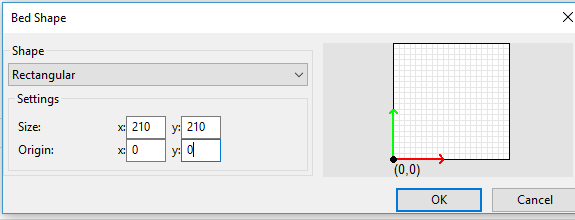
and bed like this?
mpm1396
on 20 Jan 2019
bed like that yes
boelle
on 20 Jan 2019
ok
mpm1396
on 20 Jan 2019
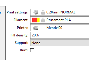
boelle
on 20 Jan 2019
i call my printer mendel90
yours should be mk2.5
boelle
on 20 Jan 2019
its mk2
mpm1396
on 20 Jan 2019
oki... does not make big difference
think we are good to try now
boelle
on 20 Jan 2019
testsl3errerrerer.zip
here is the gcode: I try it now
mpm1396
on 20 Jan 2019
hope it works
it should start with homing X and Y
then move to center and home Z
then it should do probe
then it will heat bed
then it will go to corner and heat up nozzle
then it will make a thick line close to the edge of bed to prime extruder, and then it will start print
boelle
on 20 Jan 2019
its homing y and x and now its moving x and y realy slowly to the mid
mpm1396
on 20 Jan 2019
Why is this so slow??
mpm1396
on 20 Jan 2019
Now it homed z and it is probing the bed
mpm1396
on 20 Jan 2019
we might need to change start code later if print works
did you see my list of what it should do?
boelle
on 20 Jan 2019
yes it is now heating the nozzle but bltouch is blinking red like now after finishing probing
mpm1396
on 20 Jan 2019
is pin up?
boelle
on 20 Jan 2019
i dont use bl touch so not sure why its blinking
boelle
on 20 Jan 2019
blinking means error I stopped the print and tried it again lets see
mpm1396
on 20 Jan 2019
oki.... check that it does hit the bed every time and not out in the air next to bed
boelle
on 20 Jan 2019
but i'm not sure why there should be an error, we need expert help on that
boelle
on 20 Jan 2019
it Looks good but the nozzle is to close to the bed
mpm1396
on 20 Jan 2019
there is no error any more
mpm1396
on 20 Jan 2019
oki :-D
boelle
on 20 Jan 2019
I stopped the print because the nozzle was Scratching the bad
mpm1396
on 20 Jan 2019
bed*
mpm1396
on 20 Jan 2019
but besides that it looked good
mpm1396
on 20 Jan 2019
oki.... change #define Z_PROBE_OFFSET_FROM_EXTRUDER -0.4
to
define Z_PROBE_OFFSET_FROM_EXTRUDER 0
then upload
M502
M500
it should now be 0.4mm more up in the air
boelle
on 20 Jan 2019
and yes it might move slow in start code but we can fix that
boelle
on 20 Jan 2019
By now, I think many people are monitoring this thread to see if and when you reach 1000 posts. I am impressed by the dedication to helping. Kudos for @boelle.
but we can fix that
ghost
on 20 Jan 2019
Yes :D
mpm1396
on 20 Jan 2019
i think the biggest mistake is that the board in the printer was not there and we used the wrong one
boelle
on 20 Jan 2019
ok uploaded it now its probing but now its not moving that slow
mpm1396
on 20 Jan 2019
oki...
lets hope the print goes ok
boelle
on 20 Jan 2019
no it is now even harder hitting the bed
mpm1396
on 20 Jan 2019
define Z_PROBE_OFFSET_FROM_EXTRUDER -0.8
is that better?
i always get confused on how to set this number
boelle
on 20 Jan 2019
its better but not enough i guess I ll try -1.2
mpm1396
on 20 Jan 2019
yep... change it in small steps
boelle
on 20 Jan 2019
you were right :D
its working for Offset 2 now
mpm1396
on 20 Jan 2019
let see a picture of test print :-D
boelle
on 20 Jan 2019
mpm1396
on 20 Jan 2019
Picture is coming wait
mpm1396
on 20 Jan 2019
by the way... are there a fan to blow air on controller board?
boelle
on 20 Jan 2019
mpm1396
on 20 Jan 2019
Yes There is a fan at the board
mpm1396
on 20 Jan 2019
Thank you soooooooo much for your Help.
If I got any qustions I now finally know sombody I can talk to. :D
mpm1396
on 20 Jan 2019
try #define Z_PROBE_OFFSET_FROM_EXTRUDER -1.9
but otherwise it looks very good
i have a meeting tomorrow so we cant do any more testing today, but i think you have a working setup
boelle
on 20 Jan 2019
goal with first layer is to get it smooth on both sides of the print
boelle
on 20 Jan 2019
I ll try further tomorrow :D
mpm1396
on 20 Jan 2019
you can even go with 2 decimal so -1.95
boelle
on 20 Jan 2019
i will be here tomorrow afternoon
https://mattshub.com/2017/04/19/extruder-calibration/
go down to where you see the empty box
Calibrating extrusion multiplier
do you have calipers to messure precise?
boelle
on 20 Jan 2019
I wanted to do this a while ago but I do Not have a digital caliper
mpm1396
on 20 Jan 2019
:-( but yes... at least you are now good to go :-D
remember to close this issue and the other you opened before
you can still write to me via this issue even if closed
boelle
on 20 Jan 2019
i will try and add your config to marlin now
boelle
on 20 Jan 2019
boelle
on 20 Jan 2019
configuration.h: https://github.com/MarlinFirmware/Marlin/pull/12972/commits/17ffbfd45902dc8516018801c80e13b474cbc4ad
configuration_adv.h: https://github.com/MarlinFirmware/Marlin/pull/12972/commits/d9610e456d97be5ccfa8f50aab5b161f4e65cc33
they do look correct yes?
boelle
on 20 Jan 2019
Yes i think so. How can I Close this issue?
mpm1396
on 21 Jan 2019
Look at bottom of page :)
man. 21. jan. 2019 07.04 skrev mpm1396 notifications@github.com:
Yes i think so. How can I Close this issue?
—
You are receiving this because you were mentioned.
Reply to this email directly, view it on GitHub
https://github.com/MarlinFirmware/Marlin/issues/12948#issuecomment-455957980,
or mute the thread
https://github.com/notifications/unsubscribe-auth/ADp5ryEC6O6MVA663TDJiQy_yhtRnvn4ks5vFVhigaJpZM4aIkpm
.
boelle
on 21 Jan 2019
Ohh :D
mpm1396
on 21 Jan 2019
So Ive noticied somthing, I am not sure if this is normal. I disconnected one threaded Z rod from the z motor (1) and I moved the other motor (2), the first motor (1) moves the same even if the printer is turned off
mpm1396
on 22 Jan 2019
yep.... that is normal
2 motors connected in parallel, if you move one motor fast enough the other will move too
boelle
on 22 Jan 2019
you forgot to close the other issue: https://github.com/MarlinFirmware/Marlin/issues/12970
boelle
on 22 Jan 2019
ok btw. my first print failed, dont know why, the nozzle mooved in the object. I didnt watched it. Second print turned out beautiful.
mpm1396
on 22 Jan 2019
if I want to adjust the z motor current wich driver poti do I have to turn?
mpm1396
on 22 Jan 2019
if I only touch the z rods while moving them up it looses stepps ---> cureent is to low?
mpm1396
on 22 Jan 2019
ok I turned all poti s a bit and it seems better now
mpm1396
on 22 Jan 2019
This issue has been automatically locked since there has not been any recent activity after it was closed. Please open a new issue for related bugs.
![github-actions[bot] picture](https://avatars2.githubusercontent.com/in/15368?v=4&s=40) github-actions[bot]
on 25 Jul 2020
github-actions[bot]
on 25 Jul 2020
Related issues
 pubalan12
·
4Comments
pubalan12
·
4Comments
 otisczech
·
3Comments
otisczech
·
3Comments
 modem7
·
3Comments
modem7
·
3Comments
 manianac
·
4Comments
manianac
·
4Comments
 ShadowOfTheDamn
·
3Comments
ShadowOfTheDamn
·
3Comments