Marlin: [BUG] JUNCTION_DEVIATION creates unexpected decelerations/accelerations on smooth curves
Bug Description
With Junction deviation enabled the printer decelerates and accelerates unexpectedly on smooth curves. JUNCTION_DEVIATION_MM is set to 0.017. There is no difference if I increase it to 0.2.
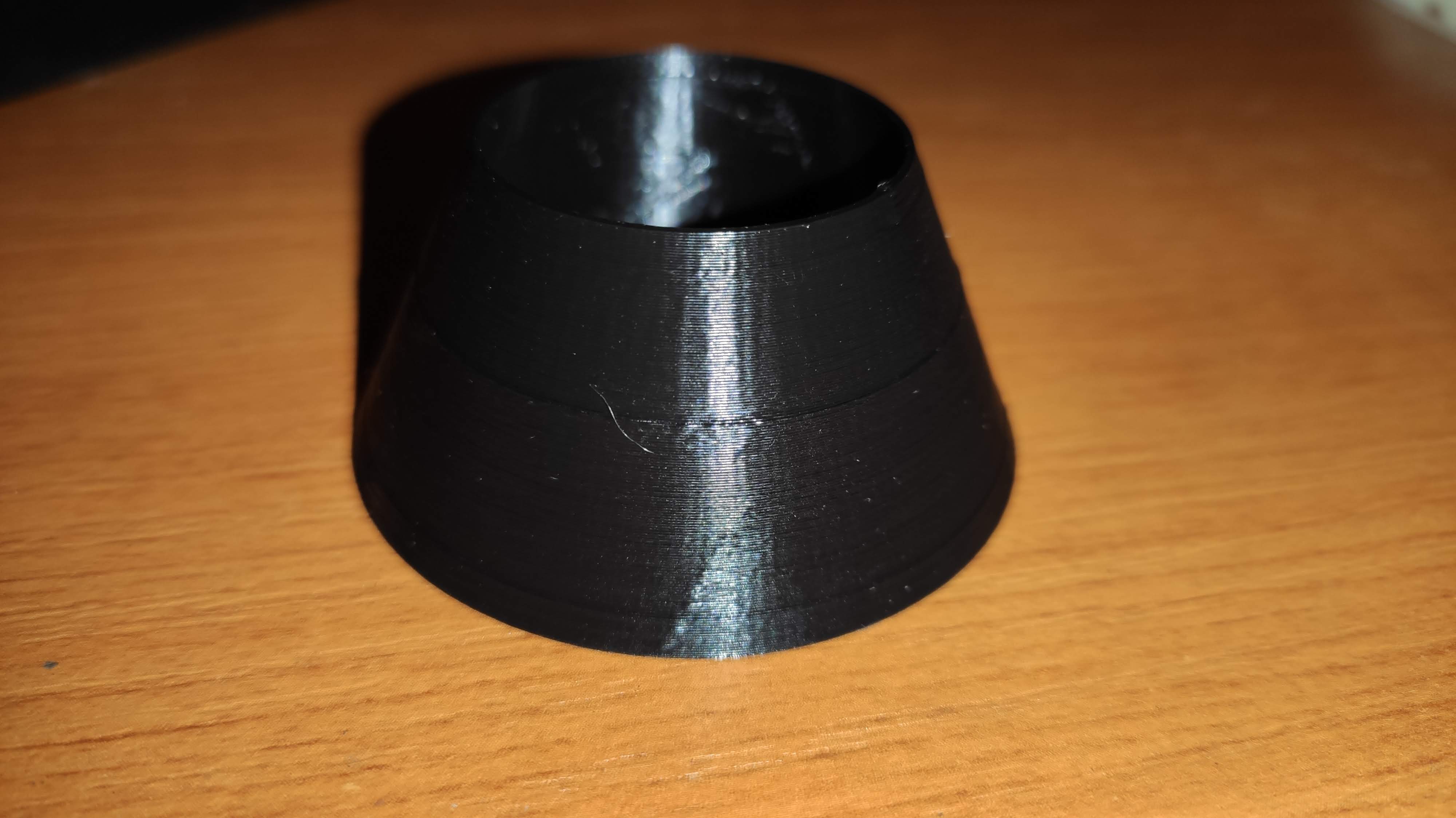
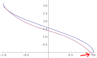
In this picture I have marked the locations where the slowdown occurs with arrows. This happens at other locations as well but these are the most obvious.

With CLASSIC_JERK the print is smooth and without unexpected deceleration / acceleration.
Example videos (look at the extruder visualizer when this happens):
With Junction Deviation = 0.017
With Classic Jerk
#define DEFAULT_XJERK 10.0
#define DEFAULT_YJERK 10.0
#define DEFAULT_ZJERK  0.3
My Configurations
LIN_ADVANCE is enabled and LIN_ADVANCE_K is set to 0.1. Settings this to 0 has no effect.
S_CURVE_ACCELERATION is enabled.
Steps to Reproduce
Print a large curved object like the one in the photo.
Expected behavior:
The curve is printed smooth, just like with classic jerk.
Actual behavior:
The curve is printed with at least decelerated/accelerated moves.
I'm using Marlin bugfix-2.0.x commit e7a9f17 from March 22nd.
 ktand
ktand
All 265 comments
17146
Have the same issue.
SKR Mini E3 v1.2, Cura/PrusaSlicer/Fusion 360
 qwewer0
on 30 Mar 2020
qwewer0
on 30 Mar 2020
Yes. I have this same problem (in fact also printing face shields :D).
Differences in setup, producing the same issue:
- You are using Slic3r and I am using Cura.
- Your board is 32 bit (ARMED STM32) and mine is 8 bit (ZUM Mega 3D).
- The STL model is different (I was printing this one).
Similarities:
- The model has arcs that are long and thin.
- S_CURVE: enabled (tested both ON and OFF, same problem).
- Junction deviation: enabled.
- LIN_ADVANCE: enabled (tested both ON and OFF, same problem).
More parameters:
- I have ADAPTIVE_STEP_SMOOTHING enabled (tested both ON and OFF, same problem).
I'm considering switching back permanently to classic jerk since it doesn't have this problem. Your help would be very appreciated!
Maybe related: #15473
 CarlosGS
on 31 Mar 2020
CarlosGS
on 31 Mar 2020
Because of this problem, I spent a lot of time testing JD and LA settings. My bottom line is to set JD much higher, certainly based on my other settings. Printing curves like @ktand in the first post with default 0.013 JD creates a lot of stuttering on my machine. Increasing JD to much higher values makes it working as expected. In my case setting JD to 0.07 stuttering gets rarely. Increasing to 0.09 makes stuttering almost gone, except small curves and corners where it does its job as expected.
Here are my config files, maybe to compare settings like acceleration, E-jerk,...
Configuration.zip
Configuration_adv.zip
 rado79
on 31 Mar 2020
rado79
on 31 Mar 2020
I increased JUNCTION_DEVIATION_MM to 0.2, almost 11 times higher, but the
problem still occurs.
Den tis 31 mars 2020 kl 19:43 skrev rado79 notifications@github.com:
Because of this problem, I spent a lot of time testing JD and LA settings.
My bottom line is to set JD much higher, certainly based on my other
settings. Printing curves like @ktand https://github.com/ktand in the
first post with default 0.013 JD creates a lot of stuttering on my machine.
Increasing JD to much higher values makes it working as expected. In my
case setting JD to 0.07 stuttering gets rarely. Increasing to 0.09 makes
stuttering almost gone, except small curves and corners where it does its
job as expected.Here are my config files, maybe to compare settings like acceleration,
E-jerk,...
Configuration.zip
https://github.com/MarlinFirmware/Marlin/files/4410644/Configuration.zip
Configuration_adv.zip
https://github.com/MarlinFirmware/Marlin/files/4410645/Configuration_adv.zip—
You are receiving this because you were mentioned.
Reply to this email directly, view it on GitHub
https://github.com/MarlinFirmware/Marlin/issues/17342#issuecomment-606773983,
or unsubscribe
https://github.com/notifications/unsubscribe-auth/AEHQ2JDBQG34PUYSMZVYDKTRKITSLANCNFSM4LW33CGA
.
ktand
on 31 Mar 2020
I increased it to 0.3mm and the problem still occurs.
El mar., 31 mar. 2020 19:56, Karl Andersson notifications@github.com
escribió:
I increased JUNCTION_DEVIATION_MM to 0.2, almost 11 times higher, but the
problem still occurs.Den tis 31 mars 2020 kl 19:43 skrev rado79 notifications@github.com:
Because of this problem, I spent a lot of time testing JD and LA
settings.
My bottom line is to set JD much higher, certainly based on my other
settings. Printing curves like @ktand https://github.com/ktand in the
first post with default 0.013 JD creates a lot of stuttering on my
machine.
Increasing JD to much higher values makes it working as expected. In my
case setting JD to 0.07 stuttering gets rarely. Increasing to 0.09 makes
stuttering almost gone, except small curves and corners where it does its
job as expected.Here are my config files, maybe to compare settings like acceleration,
E-jerk,...
Configuration.zip
<
https://github.com/MarlinFirmware/Marlin/files/4410644/Configuration.zip>
Configuration_adv.zip
<
https://github.com/MarlinFirmware/Marlin/files/4410645/Configuration_adv.zip—
You are receiving this because you were mentioned.
Reply to this email directly, view it on GitHub
<
https://github.com/MarlinFirmware/Marlin/issues/17342#issuecomment-606773983
,
or unsubscribe
<
https://github.com/notifications/unsubscribe-auth/AEHQ2JDBQG34PUYSMZVYDKTRKITSLANCNFSM4LW33CGA.
—
You are receiving this because you commented.
Reply to this email directly, view it on GitHub
https://github.com/MarlinFirmware/Marlin/issues/17342#issuecomment-606780696,
or unsubscribe
https://github.com/notifications/unsubscribe-auth/AAMPPKS64M6XGUXUT6YIQNLRKIVEDANCNFSM4LW33CGA
.
CarlosGS
on 31 Mar 2020
First, be sure to turn off all acceleration and speed tuning in your slicer. Prusa Slicer and Cura are both prone to inserting a lot of parameter changes, and this can sometimes interfere with the planner.
Unfortunately it is not a simple thing to debug dynamic issues of this kind without lots of data collection and isolation of effects. So we will need to gather as much logging as possible to determine root causes.
One thing I would note is that when doing curves you are likely to get a greater variation in linear speeds and constraints on those speeds. If you have your movement speed set very high in the slicer so you can get fast curves, you will also get a lot of places where your printer's maximum constraints come into play to alter the speed. So, you can try setting very high max-accel and max-speed values on the printer to remove those constraints.
Curves with lots of segments are also a bit more demanding, so you may also be hitting computation limits in some cases, and slowing down of the planner to keep the buffer full. If your board has lots of SRAM you can increase the buffer sizes and set the slowdown limit to a smaller proportion.
We did just fix an issue with G2/G3 arcs, but your slicer probably isn't producing those….
 thinkyhead
on 31 Mar 2020
thinkyhead
on 31 Mar 2020
One of the settings I saw CH3D point out recently was the "minimum segment length" setting in the slicer. This makes sure not to flood the machine with too many tiny segments, when a minimum length of 0.6mm would do just fine for most applications.
I don't mean to suggest that tuning slicer settings and reducing load on the machine is the ultimate solution for JD (and LA) issues, but it will help in the isolation testing.
thinkyhead
on 31 Mar 2020
These are the acceleration parameters currently set in the slicer. I will set them to 0 so that the printer defaults are used (I will also reset the printer configuration to ensure no parameters has changed) and try another print.

Regarding the slowing down I've tried the following:
- Enabled
SLOWDOWNwith aSLOWDOWN_DIVISORof 2. No difference. - Increase the
BLOCK_BUFFER_SIZEto 64, no difference.
I'm printing from SD.
Is there a different how the planner treats segments with JD vs classic jerk enabled, except from generating segments with different acceleration/deceleration? With classic jerk the print is very smooth.
Tried to find a setting regarding minimum segment length but the only settings that I could find are these:

ktand
on 31 Mar 2020
Remember to increase the SLOWDOWN_DIVISOR if you increase the number of buffer lines, otherwise it slows down too soon. With 64, a divisor of 16 should be good.
thinkyhead
on 31 Mar 2020
I tried without SLOWDOWN but with a BLOCK_BUFFER_SIZE of 64, no difference.
ktand
on 31 Mar 2020
Is there a different how the planner treats segments with JD vs classic jerk enabled…?
There is a difference in how much acceleration and deceleration are applied at the segment junctions. And there are more (expensive) calculations done at each segment junction.
Ideally, we'll need to put together a table / graph of the speeds that are being applied at the junctions, comparing classic jerk to junction deviation, and both of those to the best desired speeds.
thinkyhead
on 31 Mar 2020
Hi! Thanks for looking in to this! Is JD applied to each new motion regardless of length?
CarlosGS
on 31 Mar 2020
🌊 Is JD applied to each new motion regardless of length? 🦁
Yes.
thinkyhead
on 31 Mar 2020
OK, thanks. (I didn't put those icons.. new bug report? :p)
CarlosGS
on 31 Mar 2020
Tried to find a setting regarding minimum segment length but the only settings that I could find are these:
@ktand Where did you found it? Is it PrusaSlicer? Can't find it on 2.2
qwewer0
on 31 Mar 2020
Since this has become a duplicate of 17146 I am closing that issue to reduce noise.
thinkyhead
on 31 Mar 2020
@thinkyhead see my comment on the duplicate issue: https://github.com/MarlinFirmware/Marlin/issues/17146#issuecomment-606901454. Sloppy/low-res slicing is not a solution; it breaks other things.
 richfelker
on 1 Apr 2020
richfelker
on 1 Apr 2020
Tried to find a setting regarding minimum segment length but the only settings that I could find are these:
@ktand Where did you found it? Is it PrusaSlicer? Can't find it on 2.2
@qwewer0 I'm using Slic3r++ 2.2.48
ktand
on 1 Apr 2020
I was in the middle of writing a reply in the other report when @thinkyhead closed it so I'm just copying what I had started to type over there. It's a good idea to consolidate it to one thread anyways.
@swilkens wrote
If this is an issue specifically with the SKR Mini E3 v1.2 and maybe with other SKR boards too, then how can we make sure of it, then solve it?
I'm open to ideas.Build back your original board, use the same firmware options and verify on the original board with the same gcode?
My board is an SKR E3 DIP but that's basically the "same" as the mini I think. I do still have my original creality board but that is different stepper drivers(A4988). This weekend I could try swapping it back in just to test but I'm not sure if I could enable everything without running out of memory on it. Probably not, but i can try.
@CarlosGS @qwewer0 @ktand @rado79 and any others I may have missed. Out of curiosity what stepper drivers and exact main board is everyone using.
SKR E3 DIP v1.1 and all 4 stepper drivers are TMC2209's on my printer.
Like @thinkyhead said we need to start collecting data and logging. To try and get it as consistent across the board we should all decide on or make a fairly quick printing test model that we can all use and a list of what data we should all collect. I'm probably not the best to make those decisions but if someone writes out an almost step by step and what data points to record I'll certainly do it.
It looks like M928 can produce a log of "console and host input" and send it to the SDcard to easily grab. Is that the kind of logging you are talking about @thinkyhead? Also what M111 level would be helpful for this?
 DaMadOne
on 1 Apr 2020
DaMadOne
on 1 Apr 2020
Hi! I don't know if this help, but I'm having same problems. CJ is better but I got unexpected beheaviour on some parts. Two videos:
Junction Deviation 0.013
Classic Jerk
  #define DEFAULT_XJERK 10.0
  #define DEFAULT_YJERK 10.0
  #define DEFAULT_ZJERK  0.3
GT2560 Motherboard with mega1280. All stepper drivers are TMC2208 as standalone.
S_CURVE_ACCELERATION enabled.
#define BLOCK_BUFFER_SIZE 32
NO Linear Advance
 skarcha
on 1 Apr 2020
skarcha
on 1 Apr 2020
BQ Zum Mega 3D with integrated DRV8825 drivers
CarlosGS
on 1 Apr 2020
@CarlosGS @qwewer0 @ktand @rado79 and any others I may have missed. Out of curiosity what stepper drivers and exact main board is everyone using.
BTT SKR1.3 and TMC2208/2209, 24V
rado79
on 1 Apr 2020
@thinkyhead
I have now configured the slicer to use the same defaults as the printer's. Unfortunately this didn't help.
#define DEFAULT_MAX_FEEDRATE          { 200, 200, 30, 120 }
#define DEFAULT_MAX_ACCELERATION      { 2000, 2000, 200, 10000 }
#define DEFAULT_ACCELERATION          2000    // X, Y, Z and E acceleration for printing moves
#define DEFAULT_RETRACT_ACCELERATION  2000    // E acceleration for retracts
#define DEFAULT_TRAVEL_ACCELERATION   2000    // X, Y, Z acceleration for travel (non printing) moves
Start of G-code script:
M201 X2000 Y2000 Z200 E10000 ; sets maximum accelerations, mm/sec^2
M203 X200 Y200 Z30 E120 ; sets maximum feedrates, mm/sec
M204 P2000 R2000 T2000 ; sets acceleration (P, T) and retract acceleration (R), mm/sec^2
M205 X10.00 Y10.00 Z0.40 E4.50 ; sets the jerk limits, mm/sec
M205 S0 T0 ; sets the minimum extruding and travel feed rate, mm/sec
Inspecting the G-code file in S3D shows no speed changes in the critical areas. (Not sure I would be able to seem them if there were any though).

Regarding your suggestion:
So, you can try setting very high max-accel and max-speed values on the printer to remove those constraints.
what would be suitable values for max-accel? And for me to be sure I make the right modification, is it the DEFAULT_MAX_ACCELERATION or the DEFAULT_ACCELERATION we're talking about? I've always wondered how the DEFAULT_MAX_ACCELERATION relates to the DEFAULT_ACCELERATION. Is that just a limit or is the DEFAULT_MAX_ACCELERATION used by the planner?
ktand
on 1 Apr 2020
@CarlosGS @qwewer0 @ktand @rado79 and any others I may have missed. Out of curiosity what stepper drivers and exact main board is everyone using.
SKR Mini E3 v1.2, TMC2209
qwewer0
on 1 Apr 2020
My board is an SKR E3 DIP and TMC2208 UART drivers. But the result is the same.
 Viking117
on 1 Apr 2020
Viking117
on 1 Apr 2020
Is that a Face Mask holder for a hospital? We are printing some thing very similar to what your pictures shows in Houston. Except ours say "Houston Strong" on them!

 Roxy-3D
on 2 Apr 2020
Roxy-3D
on 2 Apr 2020
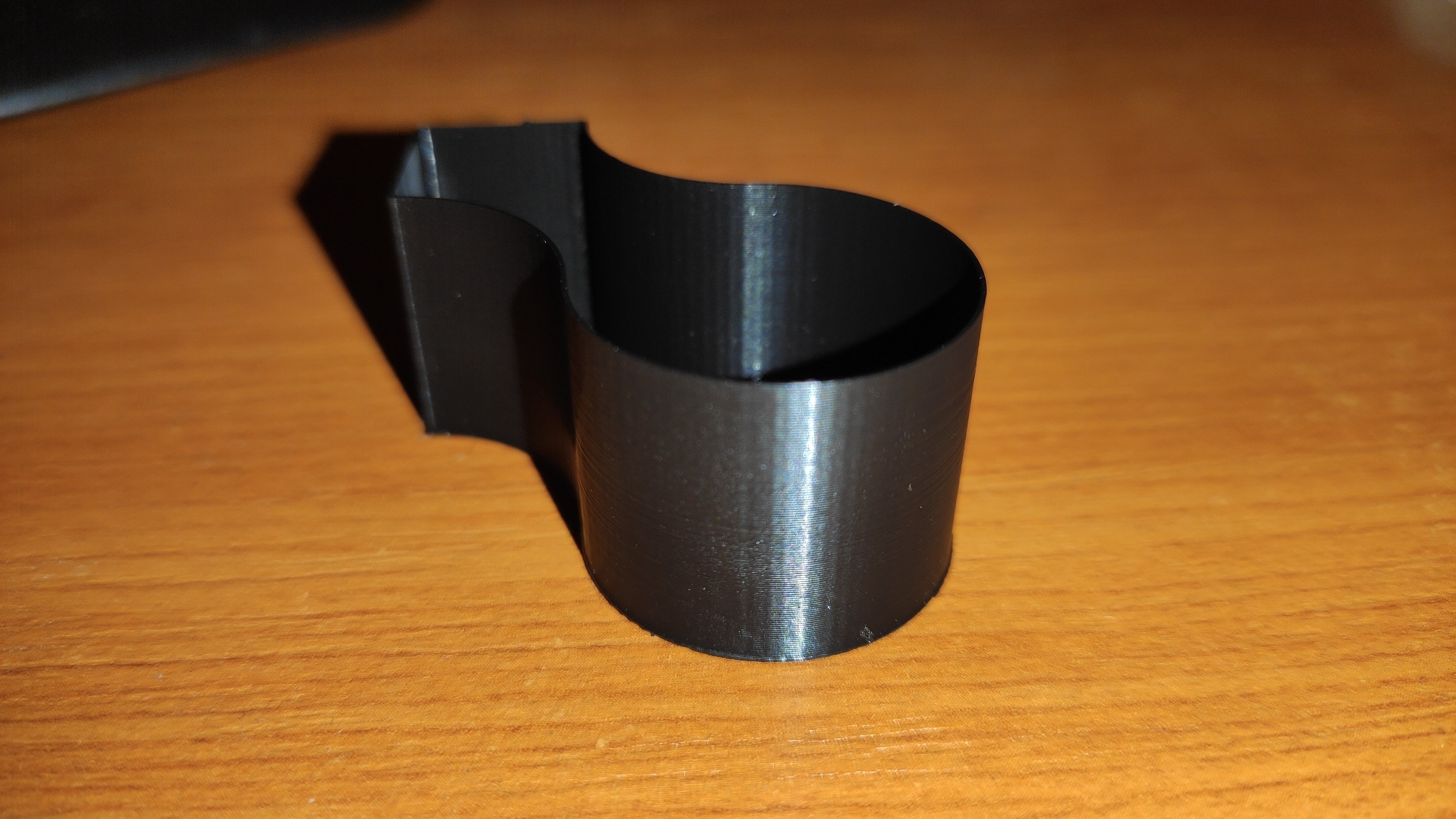
@Roxy-3D Yes it is. Link. I've delivered two batches to a local hospital.
ktand
on 2 Apr 2020
I am in complete confusion. I tried different combinations (turned on and off) of parameters:
LIN_ADVANCE
S_CURVE_ACCELERATION
CLASSIC_JERK
But I always got pimples on my model, sometimes even on straight lines. I tried to increase the maximum resolution to 0.8, the result is better but not perfect. Photo in my post on reddit https://www.reddit.com/r/ender3/comments/ft3fse/pimples_when_printing_a_3d_printer/
Is it really necessary to return to the stock board and marlin 1,1,9? (
Viking117
on 2 Apr 2020
With PrusaSlicer, in my case the jittering motion happens on the "gap fill" layers (the white traces)

Maybe the cause is that these look like arcs to us, but the gcode is different.
This is an arc in PrusaSlicer:
G1 X42.099 Y31.207 E0.10230
G1 X43.391 Y29.547 E0.17992
G1 X44.569 Y28.161 E0.15551
G1 X45.807 Y26.811 E0.15659
G1 X47.091 Y25.514 E0.15609
G1 X48.420 Y24.268 E0.15574
G1 X49.788 Y23.074 E0.15526
G1 X51.682 Y21.563 E0.20715
G1 X52.647 Y20.832 E0.10354
G1 X54.132 Y19.786 E0.15529
G1 X55.144 Y19.120 E0.10360
G1 X57.732 Y17.530 E0.25974
And this is the parallel arc segment for "gap fill" in PrusaSlicer:
G1 F7056.755
G1 X56.875 Y18.516 E0.00036
G1 F6344.481
G1 X55.363 Y19.465 E0.10529
G1 X54.418 Y20.079 E0.06647
G1 F6581.463
G1 X54.412 Y20.084 E0.00043
G1 F6541.549
G1 X54.359 Y20.120 E0.00367
G1 F6525.710
G1 X52.886 Y21.159 E0.10338
G1 X52.566 Y21.393 E0.02269
G1 F6783.652
G1 X52.560 Y21.398 E0.00046
G1 F6517.417
G1 X51.930 Y21.883 E0.04563
G1 X50.318 Y23.158 E0.11800
G1 F6861.681
G1 X50.312 Y23.162 E0.00039
G1 F6617.866
G1 X50.046 Y23.383 E0.01958
G1 X49.192 Y24.121 E0.06381
G1 F6822.325
G1 X49.186 Y24.126 E0.00041
G1 F6353.068
G1 X48.694 Y24.571 E0.03908
G1 F6333.234
G1 X47.377 Y25.807 E0.10673
G1 X46.932 Y26.241 E0.03670
G1 F6762.339
G1 X46.927 Y26.246 E0.00043
G1 F6512.778
G1 X46.100 Y27.090 E0.06787
G1 X45.896 Y27.307 E0.01709
G1 F6670.677
G1 X45.891 Y27.312 E0.00041
G1 F6227.178
G1 X44.879 Y28.434 E0.09080
G1 X44.120 Y29.307 E0.06950
G1 F6689.505
G1 X44.114 Y29.315 E0.00052
G1 F6283.570
G1 X43.710 Y29.806 E0.03789
G1 X42.420 Y31.449 E0.12439
Video of both gcodes:

CarlosGS
on 2 Apr 2020
The same test but with Cura:

So the jittery arcs in Cura also have segments with uneven length. My guess is that these were being softened by Classic Jerk and are now being noticed.
CarlosGS
on 3 Apr 2020
I have also recorded the PrusaSlicer example (updated previous post), and it shows arc segments of uneven length too. Sorry for the spam but it is looking promising!!
CarlosGS
on 3 Apr 2020
Not sure if this'll help anybody here. Although the stuttering still occurs on my machine, the extrusion seems far more reliable:
With the SKR E3 series (Mini 1.2, DIP), I found the Z stepper was missing steps (verified by M48, and hearing the probe randomly hit the bed on second deployment). The extruder was also showing very minor inconsistencies, which was revealed when I was running a 0.8 nozzle.
I tried turning on and off Stealthchop, slowing down the probing, etc, and still had issues. On average, the probing was out 0.08 to 0.1.
I recently converted the printer to 24V to see if it was a voltage issue, but the issue persisted. Finally, I changed the motor timings in Configuration_Adv.h to the DRV8825 values:
define MINIMUM_STEPPER_POST_DIR_DELAY 650
define MINIMUM_STEPPER_PRE_DIR_DELAY 650
define MINIMUM_STEPPER_PULSE 2
define MAXIMUM_STEPPER_RATE 250000
Immediately, my M48 dropped to 0.001. The stutters are still there, but the extrusion seems far cleaner.
 XBrav
on 5 Apr 2020
XBrav
on 5 Apr 2020
I've always wondered how the
DEFAULT_MAX_ACCELERATIONrelates to theDEFAULT_ACCELERATION. Is that just a limit or is theDEFAULT_MAX_ACCELERATIONused by the planner?
These are just the defaults that you set in the configs. The planner uses the current values. The current values may been loaded from EEPROM or may have been altered by M201 / M204.
- Max Acceleration: All accelerations are clamped to this value.
- Acceleration: The acceleration that will be used for the next move.
Jerk, junction deviation, and move prediction rely on the current acceleration and feedrate values, so it does seem like changing the feedrate or accelerations constantly throughout a move could undermine the planner. It would be good to compare very clean G-code that doesn't change feedrates except when going between feature types (infill vs. walls) to G-code that changes motion parameters more often.
I'm not sure why the G-code above does separate G1 F commands when the F parameter could be on the end of the following line instead. That would make it slightly leaner.
thinkyhead
on 5 Apr 2020
This is worth a read for anyone using 2208 and 2209… https://github.com/MarlinFirmware/Marlin/issues/11825#issuecomment-421809385
thinkyhead
on 6 Apr 2020
@thinkyhead Didn't worked for me. https://github.com/MarlinFirmware/Marlin/issues/17146#issuecomment-609656052
qwewer0
on 6 Apr 2020
This is worth a read for anyone using 2208 and 2209… #11825 (comment)
Hello all! so I read that and what I took away from it was maybe stealthchop was the issue? or am I reading that wrong?
I received a micro-swiss direct drive kit to go with their hot end I already had for my ender 3 pro and installed it. I wen't with 2.0.x bugfix(as of yesterday) just to have the latest and set it up. Calibrated e-steps, flow and k value. Need to tune more but these were what I thought to be important to get me going and testing for this "bug"
Part of me hoped that by switching to this setup and being able to really lower my retraction which I have not REALLY calibrated yet but am running at 1mm @ 25mm/s and am getting decent results. Add that to a much lower k value of 0.08 and I was hoping the issue would go away. *hint... no such luck! :(
I broke out the trusty tux model and sliced out a bit of the middle section and after the first slower layer printed I could immediately hear the familiar sound of the extruder going nuts, but much more subtle now. In the end the "skin" of the tux model ended up looking almost the same as it had with JD/LA enabled before the direct drive as outlined in #17146 OP.
So I thought lets test out this stealthchop theory and printed the same gcode again but in the middle of it I sent an 'M569 S0 E' which I knew put the extruder stepper into spreadcycle mode because I could hear it but I also verified it on the Ender 3 LCD in advanced settings/TMC Drivers and also with M569 after the print was done which showed "E driver mode: spreadCycle"
I printed half the model with stealthchop and half with speadcycle and can't tell the difference. The extruder stutter remained even with spreadcycle.
@thinkyhead. Since I'm using a board with driver sockets I'm willing to order another stepper driver or two and test with them to try and see if this is a TMC2208/9 issue but I would like some input from someone in the know about what to order. A different TMC driver(maybe 5160)? A bog standard A4988? DRV8825? I would even ask if anyone has a few different drivers sitting around who might not have the time or want to test them out to mail them to me and I'll mail them back. I would just ask that the sender REALLY clean them with some IPA and I would do the same before sending them back.
DaMadOne
on 7 Apr 2020
So I thought lets test out this stealthchop theory and printed the same gcode again but in the middle of it I sent an 'M569 S0 E' which I knew put the extruder stepper into spreadcycle mode
@DaMadOne Isn't the X and Y axis is the problem here?
qwewer0
on 7 Apr 2020
Tested with A4988 drivers. Same issue.
skarcha
on 7 Apr 2020
I can confirm that I have the same issue on the curve on this part from a TeachingTech Thingiverse collection. It only appears around layers 100 to 125 at 0.2 mm LH.
Hardware:
Stock Ender 3 Pro
Creality 1.1.4 board
ATMega 1284
A4988 drivers
Firmware:
Marlin 1.1.9 (1.1.x release branch from 05.04.20, NOT the bugfix branch)
Current config
--> Also tested with different settings: Linear Advance en-/disabled, S-Curve en-/disabled, Adaptive Step Smoothing en-/disabled. Those have _no effect_ on the issue.
Slicer:
Cura 4.5, acceleration & jerk control disabled
GCode
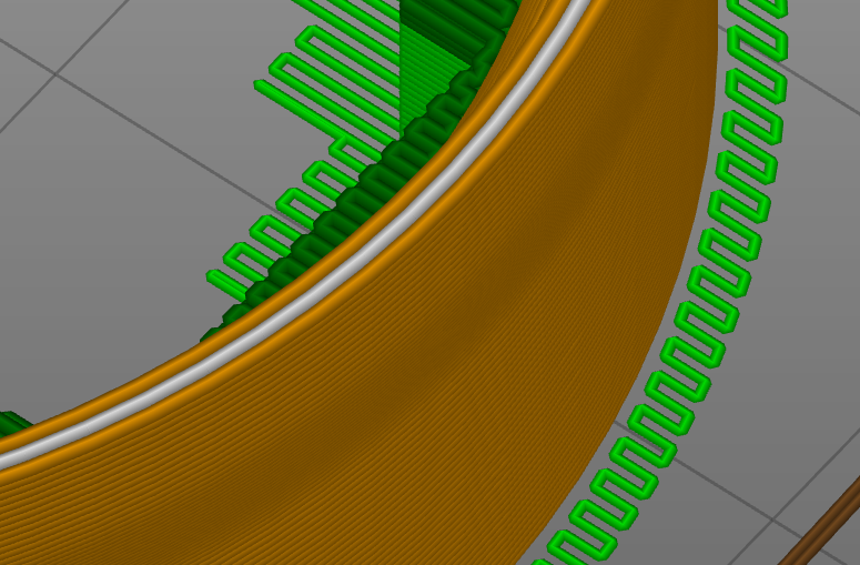
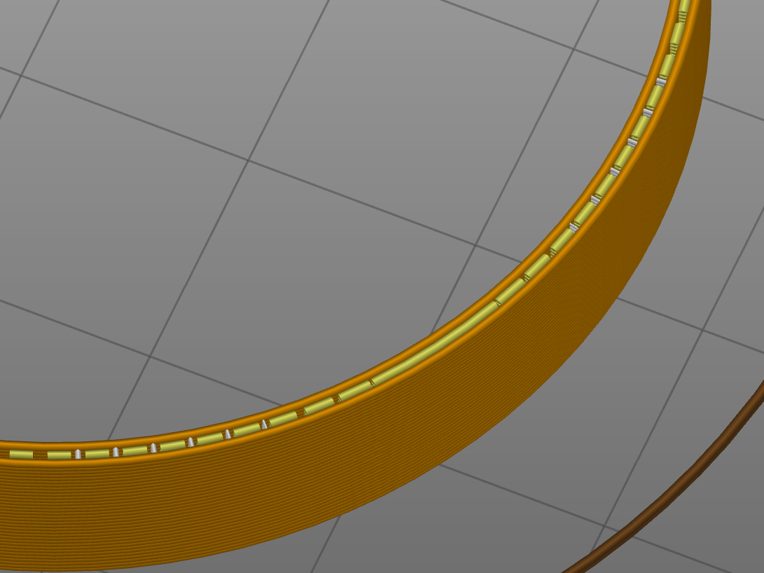
--> I can also confirm the already mentioned _inconsistent / quickly alternating_ segment length on the affected layers in the affected regions of the part. These are visible in the Cura preview. While on non-affected layers, segments in the curve are of about equal length, the segments on the affected layers are alternating short/long/short/long in comparison. However, this does not affect prints with classic Jerk at all. Only prints with Junction Deviation are deteriorated.
 XDA-Bam
on 10 Apr 2020
XDA-Bam
on 10 Apr 2020
Same issue with Sidewinder-X1 - Reducing resolution did not help. Slicing with Cura produces worse results than Slic3r, however both are back to great once I deactivate JD
 thierryzoller
on 11 Apr 2020
thierryzoller
on 11 Apr 2020
I have found a workaround for the issue, which eliminates the problem for my test print: By increasing MIN_STEPS_PER_SEGMENT from the default 6 to 16 (which is 1/2 nozzle diameter for me), the curve becomes perfectly smooth when using JD. I didn't test any lower values, so 10 or 12 steps per segment may already be enough. This is certainly not a fix, because it slightly reduces precision.
XDA-Bam
on 12 Apr 2020
It's very interesting that increasing MIN_STEPS_PER_SEGMENT has a positive effect. Certainly we don't want a million blocks with only one step in them, since this makes any acceleration / deceleration turn into a floating point square root party, and there are bound to be other potential pitfalls with many tiny segments.
Once I have more free time I will have to dive into a deeper analysis to see what the MIN_STEPS_PER_SEGMENT change is mitigating, and then figure out an earlier point to apply mitigation.
In the meantime, I would enjoy hearing from others what their experiences are in playing with MIN_STEPS_PER_SEGMENT, and if there are any "magic" thresholds that differ depending on hardware.
thinkyhead
on 12 Apr 2020
For me I have to set JD to its lowest possible value of 0.010
Anything higher creates artefacts
 Grogyan
on 12 Apr 2020
Grogyan
on 12 Apr 2020
I do not see slowdown on SKR PRO during printing of gcode with lots of small segments. But surface quality difference between JD and Jerk is still there. MIN_STEPS_PER_SEGMENT did not changed it much.
I see hardly any differences in surface quality for MIN_STEPS 6 and 16. MIN_STEPS 16 has slightly less "noise" on the surface, but still very far from JERK quality.
Jerk surface quality is better with all MIN_STEPS values (16, 6, 1).

 BarsMonster
on 12 Apr 2020
BarsMonster
on 12 Apr 2020
@BarsMonster You're using different hardware than me. Are 16 steps also equivalent to 0.2 mm in your case? That's what you should aim for. I Have 80 steps/mm on X and Y, therefore MIN_STEPS_PER_SEGMENT = 16 filtered out all the tiny segments <0.2 mm from the GCode.
XDA-Bam
on 12 Apr 2020
What size circumference are you using to see the stutters? I've put together a test stl / gcode just to see if I can see any artifacts. Here's the files. You may want to stretch it vertically if you want more comparison layers, but I included a gcode file from S3D at 0.2mm layer height at 0.4mm:
https://drive.google.com/open?id=1zZSb3GSWtmA65jmILRCykF0DZYADhaPb
Each ring has a different edge count. Bottom layer is a standard circle in Fusion 360. The next layer has 1000 edges, followed by 500, 100, and 50.
One change I've been playing with is increasing the buffer size. I noticed 16 seems to be a bit rough with lots of tiny movements. With my 32 bit board having lots of RAM, I increased it to 128:
#if ENABLED(SDSUPPORT)
  #define BLOCK_BUFFER_SIZE 128 // SD,LCD,Buttons take more memory, block buffer needs to be smaller
My results seem to be quite smooth, even with the MIN_STEPS_PER_SEGMENT = 1. This is on an Ender 5 with a E3 DIP STM32F103RC with all steppers as TMC2208 and LA enabled. I also ran the print at 300% speed just to see if I was saturating the 128 buffer. Stealthchop was turned off for the extruder as I managed to stall it with it enabled.

EDIT Added a 'tall' version that's stretched 500% on the Z. Will update with photo.
EDIT 2 Tall results at 300% speed:

XBrav
on 12 Apr 2020
@XDA-Bam @XBrav I was testing on R=8mm features, which is probably too tight. Probably cone in vase mode would be more efficient and cover all curvatures. My curves are exported with maximum resolution in Fusion, and sliced in Cura with maximum resolution so it definitely pushes the limit.
Steps per mm is 160 in my case, so yes, seems like higher MIN_STEPS would be needed in my case according to your formula. I will test min steps = 32.
BLOCK_BUFFER_SIZE is 64 in my case.
BarsMonster
on 13 Apr 2020
@XDA-Bam Tested with MIN_STEPS_PER_SEGMENT=32. "Noise" is still the same in amplitude, but lower in frequency. Probably on larger circles it would be less visible, but at R=8mm it is still very significant and significantly degrades surface quality.
BarsMonster
on 13 Apr 2020
Could I get a little information about BLOCK_BUFFER_SIZE, BUFSIZE, TX_BUFFER_SIZE, to what those do in our cases?
qwewer0
on 13 Apr 2020
I do not see slowdown on SKR PRO during printing of gcode with lots of small segments. But surface quality difference between JD and Jerk is still there. MIN_STEPS_PER_SEGMENT did not changed it much.
I see hardly any differences in surface quality for MIN_STEPS 6 and 16. MIN_STEPS 16 has slightly less "noise" on the surface, but still very far from JERK quality.
Jerk surface quality is better with all MIN_STEPS values (16, 6, 1).
I can't seem to replicate this on my SKR Mini V1.2 running 2.0.5.3, also printed with JD and Classic Jerk. Sliced with PrusaSlicer 2.2.0 at max resolution possible. S_CURVE_ACCELERATION was enabled while LINEAR_ADVANCE was disabled.
I'm also not sure this is the same issue as OP, who seems to have shown this happens with fill segments - which this model doesn't have.

 swilkens
on 13 Apr 2020
swilkens
on 13 Apr 2020
@swilkens Linear Advance?
qwewer0
on 13 Apr 2020
@swilkens Linear Advance?
No, I'm not using Linear Advance. It is enabled in the firmware, but the K value is set to 0 - the same as in the first post of this topic.
I also don't think LA would have a strong effect on this geometry, as the outer line is a of constant tangency. But I am checking now.
swilkens
on 13 Apr 2020
Can't reproduce the issue with @BarsMonster 's test file with JD. (SKR Mini E3 v1.2)
Mine is smooth as @swilkens 's
Will try with increased MIN_STEPS_PER_SEGMENT, with a different model.
qwewer0
on 13 Apr 2020
@swilkens Linear Advance?
No, I'm not using Linear Advance. It is enabled in the firmware, but the K value is set to 0 - the same as in the first post of this topic.
I also don't think LA would have a strong effect on this geometry, as the outer line is a of constant tangency. But I am checking now.
A heads up, LA with K=0 is not the same as compiling without it from what I've heard. If you have no need for LA, comment out the define and recompile.
Not saying it is a solution for you, just a note.
 randellhodges
on 13 Apr 2020
randellhodges
on 13 Apr 2020
A heads up, LA with K=0 is not the same as compiling without it from what I've heard. If you have no need for LA, comment out the define and recompile.
Not saying it is a solution for you, just a note.
I'm not sure that's true.
if you only need to have a part printed fast without special needs in terms of quality, there is no reason to enable LIN_ADVANCE at all. For those prints, you can just set K to 0."
https://marlinfw.org/docs/features/lin_advance.html
 patriot1889
on 13 Apr 2020
patriot1889
on 13 Apr 2020
Feel free to look at the code and verify code execution/planner queue is not the same. If it was the same, then they'd just default it to enabled with K=0.
I realize the web site says that, but I'm talking not talking about outcome, I'm talking about specific code that is executed with K=0 vs not enabled. Compiled result is different. X/10 times might yield the out visible result.
You might think of it as All roads lead to Rome, but each road is different and you might get lost on the lesser traveled paths.
randellhodges
on 13 Apr 2020
Exactly. For example, it is also different to compile with Junction Deviation and set it to zero than to compile with Classic Jerk and set it to zero. The goal is that there are no _apparent_ differences... but internal code is what brought us here ;)
Uptate: In my case I've been observing the printer with Classic Jerk and it is also slightly "shaky" in the gap fill parts. I would also need to test changing the buffer size and min_steps_per_segment but don't have the time to do this properly :(
Looking forward to learning the cause & solution, stay safe!
CarlosGS
on 13 Apr 2020
Exactly. For example, it is also different to compile with Junction Deviation and set it to zero than to compile with Classic Jerk and set it to zero. The goal is that there are no _apparent_ differences... but internal code is what brought us here ;)
Uptate: In my case I've been observing the printer with Classic Jerk and it is also slightly "shaky" in the gap fill parts. I would also need to test changing the buffer size and min_steps_per_segment but don't have the time to do this properly :(
Looking forward to learning the cause & solution, stay safe!
Well, that's different. JD is only enabled by specifically disabling classic jerk. Therefore JD 0 would be no JD and no Jerk, correct?
And fair enough @randellhodges. I agree in regards to this testing that LA K0 != JD OFF.
I was commenting more on the fact that it has visible difference... but really that's irrelevant to this issue so... my bad.
patriot1889
on 13 Apr 2020
I verified g-code generated by Cura, which shows the issue.
Print segments are 0.4-0.6mm in length, extrusion multiplier (how much filament is extruded vs movement length) is the same for all moves (within 0.1%). So it seems gcode is correct. With that I am not sure how MIN_STEPS_PER_SEGMENT could affect the prints as all segments are larger than 32 steps. (160 steps per mm in my case)
@swilkens @qwewer0 Could you try to print in vase mode or use my gcode? Probably gradual change of Z makes it visible.
I wonder what is Z-jerk when using JD? If Z changes often, and Z-jerk is 0 with JD, these tiny moves on Z movement could be very slow and cause surface defects.
BarsMonster
on 14 Apr 2020
With or without vase mode, can't reproduce the issue on Xtest-HR.stl
qwewer0
on 14 Apr 2020
@BarsMonster @qwewer0 for me the problem appears in the "gap fill" which aren't generated in your slicing settings, see these comments above
CarlosGS
on 14 Apr 2020
However, your code has uneven Z steps:
G1 X143.954 Y66.913 E1745.41495
G1 X144.322 Y66.652 Z13.002 E1745.43261
G1 X144.7 Y66.403 E1745.45033
G1 X144.895 Y66.282 E1745.45931
G1 X145.282 Y66.057 E1745.47684
G1 X145.483 Y65.948 E1745.48579
G1 X145.878 Y65.747 Z13.003 E1745.50314
G1 X146.294 Y65.555 E1745.52108
G1 X146.71 Y65.38 E1745.53874
G1 X147.126 Y65.224 E1745.55614
G1 X147.337 Y65.151 E1745.56488
G1 X147.774 Y65.014 Z13.004 E1745.58281
G1 X148.201 Y64.897 E1745.60014
G1 X148.64 Y64.793 E1745.6178
G1 X149.09 Y64.704 E1745.63576
G1 X149.535 Y64.633 Z13.005 E1745.6534
G1 X149.976 Y64.579 E1745.67079
G1 X150.206 Y64.558 E1745.67983
G1 X150.535 Y64.533 E1745.69275
G1 X150.993 Y64.515 E1745.71069
G1 X151.438 Y64.513 Z13.006 E1745.72811
G1 X151.79 Y64.523 E1745.7419
If you have different acceleration for Z this may be causing shaking.
CarlosGS
on 14 Apr 2020
@CarlosGS Z steps are monotonic, with 1um steps. Having Z coordinate on each line would require like 50nm (0.05um) resolution on Z axis which is hardly helpful. I agree that Z steps could cause the issue, but it's hard to make it smaller than 1um.
BarsMonster
on 14 Apr 2020
Tested the bottom of the penguin model with default MIN_STEPS_PER_SEGMENT 6 and 16 as @XDA-Bam wrote, but the results are the same. (penguin has no gap fill, but still has jitteriness) (Left 6, Right 16)
Penguin model has less triangles and those are larger than in Xtest-HR.stl, but still Xtest-HR.stl is smooth and the penguin is jittery.
qwewer0
on 14 Apr 2020
@BarsMonster I can't trigger this issue on your model, regardless of vase mode, lin_adv, classic jerk of juction deviation settings.
@CarlosGS I can't seem to force a slice where the fill is of uneven lengths as you showed in the gcode analysis of the face shield. I took the same model and sliced, all similar arc lengths. It appears that this is only happening for specific slices of specific shell thickness / nozzle width configuration in slicers. I imagine also the STL quality affects this. What is your configured nozzle diameter in prusa? which version of prusa slicer are you using?
To replicate this here, we need a small simple model that triggers this reliably.
swilkens
on 14 Apr 2020
@BarsMonster Ah! Did you try with and without vase mode? (Only printing 1 perimeter too)
@swilkens 0.4mm for both Cura and Prusaslicer, though it also depends on infill overlap.. too many parameters x)
CarlosGS
on 14 Apr 2020
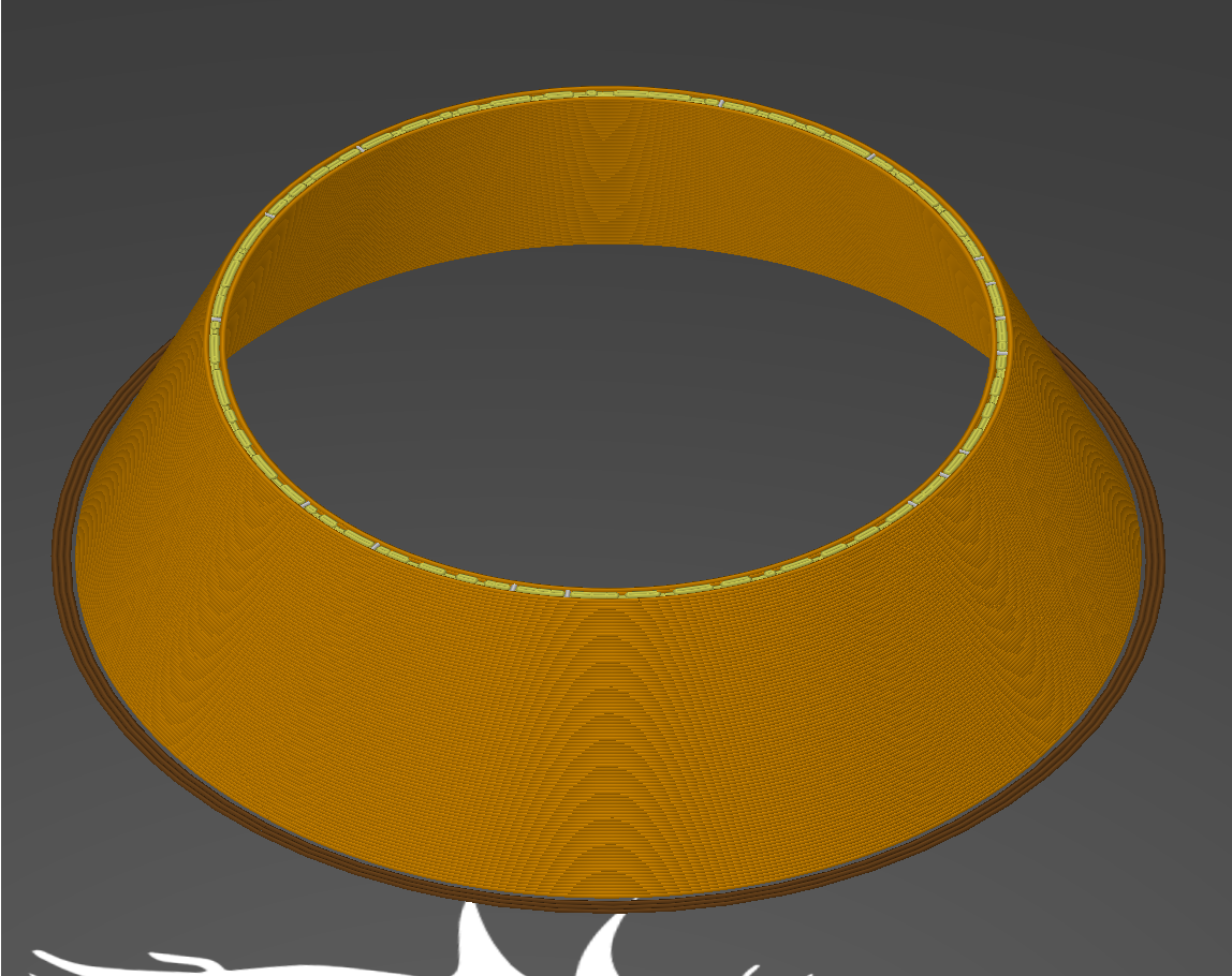
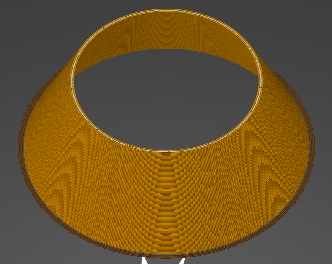
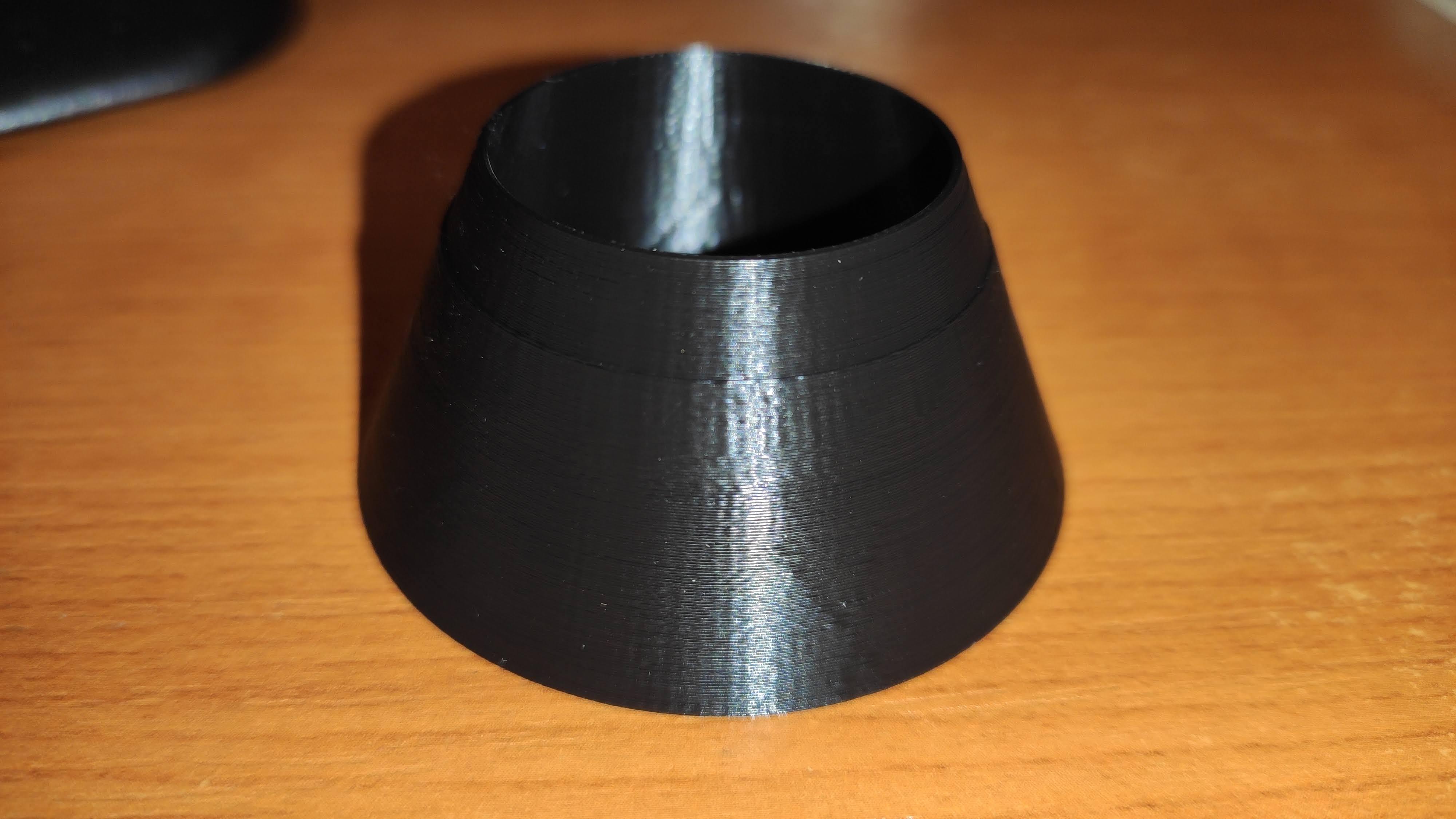
@CarlosGS I made a simple cone that goes from 2.0 mm thickness in the bottom to 0.6 mm thickness in the top, this should guarantee fill lines occurring over a part of the total height regardless of nozzle settings.
I still can't get it to slice in such a way that these variable segment length fills happen. Can you try to slice the same STL and check the fill segment lengths? I'm using PrusaSlicer 2.2.0
Even better - can you provide GCODE that triggers this?
swilkens
on 14 Apr 2020
@swilkens OK I've tried with standard PrusaSlicer settings, this is the result:
Great model BTW, the perfect test for "arcing" gap fill!
CarlosGS
on 14 Apr 2020
I still can't get this to misbehave, are you printing from SD card or over the serial interface (e.g. via octoprint or something)?
Possibly related: https://github.com/MarlinFirmware/Marlin/issues/17117
swilkens
on 14 Apr 2020
With the cone, I got a somewhat ok result, except for two layer where there was small segmented gap fill. On the upper and lower parts the issue is there, but not as noticeable as on the line in the middle. So, maybe if I got more of those gap fills then the results would have been awful.
qwewer0
on 14 Apr 2020
Gents please attach slicer 3mf projects saves, this allows us to automagically have all your settings and hence slice in exactly the same way. I start wonderin whether this doesn't slowly turn into a slicer bug report rather than a marlin one.
thierryzoller
on 14 Apr 2020
I believe that the reason why CURA results seems to have been worse than Slic3r results can be related to (in my case) the following examples.Note that the Slic3r results with JD where also bad even without the jiggling inner wall.
Slic3r
Cura

thierryzoller
on 14 Apr 2020
Here is a slice by Slic3r with slighty different settings. We will be unable to find the root cause easily because I think it is an overlay of firmware settings, slicer settings and 3d model that produces these inconsistent end results. Compare to the above :
thierryzoller
on 14 Apr 2020
That's not gapfill in slic3r (that is a grey-white line)- what you have is Infill mixed with Gapfill perpendicular lines.
Got it.
qwewer0
on 14 Apr 2020
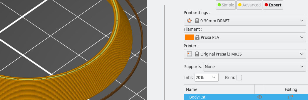
Gents please attach slicer 3mf projects saves, this allows us to automagically have all your settings and hence slice in exactly the same way.
Here is my cone: Body1.zip
I start wonderin whether this doesn't slowly turn into a slicer bug report rather than a marlin one.
The penguin model has no gap fill, yet can see the rough outside with JD, but the different slicers (Cura, PrusaSlicer, Fusion 360) still have an affect on it.
Slicer settings like weird fills between two outside lines will produce rough surface.
But, the same gcode that is ugly with JD is smooth with CJ.
qwewer0
on 14 Apr 2020
@qwewer0 : can you try and print this :
Body1_tzo.zip
thierryzoller
on 14 Apr 2020
@qwewer0 : can you try and print this :
Body1_tzo.zip
Yes, it will take 30+ min to print it.
Only with JD?
qwewer0
on 14 Apr 2020
@thierryzoller This is the result. It is the same as it was, just the ugly layer went up, because the line width is 0.3 from 0.36.
qwewer0
on 14 Apr 2020
"Fill gaps in walls" can cause problems with tiny extrusions and/or gaps between the walls on curved objects. I've had it happen two weeks ago on a totally different design. In Cura, it's a known bug. That's not a problem with JD, but there definitely is a problem with JD, too. Maybe we should take gap fill out of the equation for now and focus solely on curved surfaces and artifacts? Use thin-walled objects and avoid gaps?
This is my print, wall thickness 2, no infill or gap fill (also not necessary):
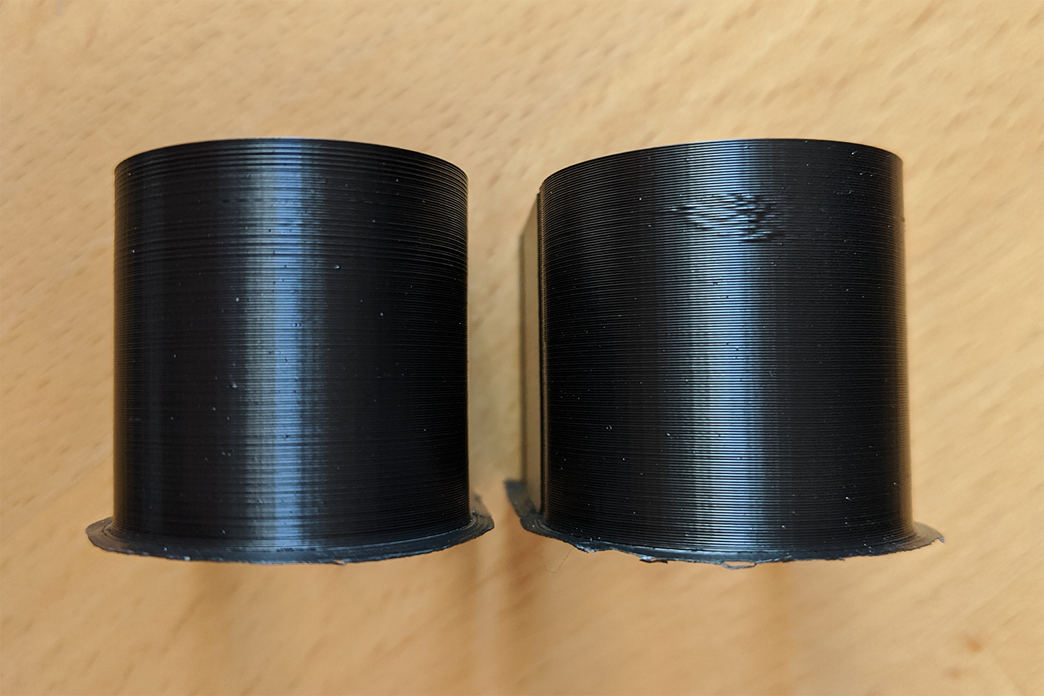
Jerk left, JD right. The curve is R=15, printed @ 100 mm/s with 750 mm/s² accel.
XDA-Bam
on 14 Apr 2020
Can we have this as a 3MF file?
thierryzoller
on 14 Apr 2020
Thanks for the detailed test, it is clear now:
Notice there are still segments of different lenght and they match the area distorted with JD!!
G1 X139.056 Y114.37 E1229.2764
G1 X139.179 Y114.987 E1229.29733
G1 X139.276 Y115.613 E1229.3184
G1 X139.286 Y115.715 E1229.32181
G1 X139.345 Y116.248 E1229.33964
G1 X139.35 Y116.339 E1229.34267
G1 X139.386 Y116.874 E1229.36051
G1 X139.387 Y116.965 E1229.36354
G1 X139.399 Y117.592 E1229.38439
G1 X139.38 Y118.241 E1229.40599
I'm using https://ncviewer.com/ to view the paths & find these.
After seeing this, it matches with previous1 & previous2. Yes those were with Gap Fill and not in the perimeters, but the result is the same: random short segments interleaved with the equidistant ones.
CarlosGS
on 14 Apr 2020
Slightly off topic, but I wonder if something like this experimental plugin would help much:
https://community.octoprint.org/t/new-plugin-anti-stutter-need-testers/18077
The idea is that it would turn all those tiny segments into an arc move. The tiny segments that make up a curve seems to be the problem, or at least a big contributor.
Looks like that code could also find its way into a cura plugin.
randellhodges
on 14 Apr 2020
Here is my result on the Teaching_Tech_speed_test.stl, and the 3mf file: Teaching_Tech_speed_test.zip
Can't see or feel any difference between them.
Left JD, Right CJ

Edit: I would love to see arc support in slicers...
qwewer0
on 14 Apr 2020
@XDA-Bam Could you please test this G-code that simply repeats the problematic arc?
JD_single_arc_test.zip
Please note that I've removed all extrusion/temperature related parts. If you can see the same misbehavior, it means that the problem is not related to extrusion but XYZ motion. I've tested it on my printer with Classic Jerk and there is no visible stuttering.
CarlosGS
on 14 Apr 2020
@qwewer0 It's best to use my GCode if you want to compare, because it's got those tiny line segments around layer 120. This is where the artifacts appear for me. Also, you won't see them on the bottom layers. So only printing the lower section will always look OK. You might get away with only printing the top third - didn't test that, yet.
@CarlosGS I'll look into it.
XDA-Bam
on 14 Apr 2020
@XDA-Bam You might be right, but I didn't just printed the bottom part, but squashed it in Z.
qwewer0
on 14 Apr 2020
@XDA-Bam Could you please test this G-code that simply repeats the problematic arc?
JD_single_arc_test.zipPlease note that I've removed all extrusion/temperature related parts. If you can see the same misbehavior, it means that the problem is not related to extrusion but XYZ motion. I've tested it on my printer with Classic Jerk and there is no visible stuttering.
This is a smart way to do this, thanks.
No stutter on Classic Jerk, seems to stall on the apex of the curve with Junction Deviation. Massive difference for me, it appears to slow down dramatically halfway during the curve with JUNCTION_DEVIATION
swilkens
on 14 Apr 2020
@CarlosGS The JD_single_arc_test.gcode with CJ it feels ok, but with JD it is noticeably more jittery.
qwewer0
on 14 Apr 2020
Aw yeah!! :)
If more people can confirm this, then we can start debugging!
CarlosGS
on 14 Apr 2020
Results so far, all was done on Marlin 2.0.5.3 release with the The JD_single_arc_test.gcode file from @CarlosGS on an SKR Mini V1.2 with TMC 2209's.
Print started from SD Card as well as via Serial interface, no difference.
LINEAR_ADVANCE doesn't seem to affect it, neither does the stepper mode. But increasing MINIMUM_STEPS_PER_SEGMENT to 16 (up from 6) certainly improved the situation dramatically. I assume this binds some of the smaller segments together.
S_CURVE_ACCELERATION also had no effect.
On a side note - it would be nice if these features could be turned on / off with a configuration setting if the device has sufficient RAM to compile them in.
STUTTER | CJ | JD | LA | Mode | MIN_STEPS_PER_SEG. | S_CURVE_ACC.
------------ | ------------ | ------------- | ------------- | ------------- | ------------- | -------------
NO | Y | - | Y | Stealth | 6 | Y
YES | - | Y | Y | Stealth | 6 | Y
YES | - | Y | - | Stealth | 6 | Y
YES | - | Y | - | SpreadCycle | 6 | Y
IMPROVED | - | Y | - | Stealth | 16 | Y
YES | - | Y | - | Stealth | 6 | -
swilkens
on 14 Apr 2020
With JD and MIN_STEPS_PER_SEGMENT 16 the JD_single_arc_test.gcode is close to the CJ results, and has definitely less stutter, but it is still not as smooth as with CJ. So over all it helped, but didn't solved it.
qwewer0
on 14 Apr 2020
To replicate the table of @swilkens and summarize my tests (ASS is adaptive steps smoothing):
| Jerk type | LA | S-Curve | ASS | Min Steps | Stutter |
| --- | --- | --- | --- | --- | --- |
| JD | - | ON | ON | 6 |YES |
| JD | ON | - | ON | 6 | YES |
| JD | ON | - | - | 6 | YES |
| JD | ON | - | - | 16 | MUCH LESS* |
| CJ | ON | - | - | 6 | NO |
(*: Since I now know what to look for, I can still make out 3 tiny stutters on the surface even with MIN_STEPS_PER_SEGMENT = 16. But that's about 90% less than with 6 steps.)
XDA-Bam
on 14 Apr 2020
@CarlosGS I just tested your JD_single_arc_test.gcode and can confirm:
- With JD, there is noticeable jitter. The Y-axis stutters about half way around the arc for a couple short steps. The X-axis sounds very rough but doesn't feel that bad.
- With CJ, both axis are much smoother, there is no hard stutter on Y and X sounds normal & smooth.
XDA-Bam
on 14 Apr 2020
Looking in the right direction! Could you give a try to compile with JD and set it to zero? I want to know if it still produces the stuttering. [DISMISS THIS]
CarlosGS
on 15 Apr 2020
I'm not too familiar with the code, but this line might be the problem. It seems to reduce speed for small segments:
https://github.com/MarlinFirmware/Marlin/blob/fc11e7217460056473f91dfb7dd574884319f567/Marlin/src/module/planner.cpp#L2354
In the example arc gcode the regular segments are ~0.6mm and the tiny ones ~0.1mm, which would translate in suddenly resetting the limit_sqr variable down to a 17% of its normal value during the arc.
CarlosGS
on 15 Apr 2020
@CarlosGS I've compared JD code to GRBL implementation.
GRBL does not have this whole section "if (block->millimeters < 1) {", and does not try to limit speed for small segments. I am not sure what was the purpose of the special treatment of small segments. I will try to find a commit which introduced this special treatment of small segments.
The rest of JD math is almost identical.
BarsMonster
on 15 Apr 2020
So this is the commit that introduced code for handling of small print segments with JD: https://github.com/MarlinFirmware/Marlin/commit/a11eb50a3eab6d58d595a67e526fb51190018db3#diff-e4800bd68f101b55ac4ff95513184458
Comment was "Better encapsulation and considerably reduce stepper jitter"
It was authored by @ejtagle and commited by @thinkyhead
Probably they might know more.
On my side - I tried to (incorectly) replace approximate math with hardware FPU call to acos() - which made whole print infinitely slower (i.e. condition always taken). So probably this section does not trigger for all small segments but rather only for few of them, which might be the cause of this noise on the surface.
BarsMonster
on 15 Apr 2020
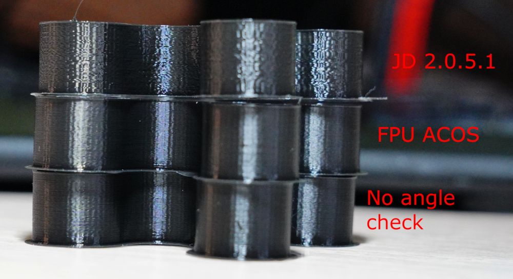
Ok, we are getting somewhere.
So in planner.cpp with (surely this could only be done as a test on a platform with HW FPU)
const float junction_theta = acos(junction_cos_theta);
instead of
const float junction_theta = (RADIANS(-40) * sq(junction_cos_theta) - RADIANS(50)) * junction_cos_theta + RADIANS(90) - 0.18f;
noise on the surface is gone. If I correctly understood intention of the code, we can just compare junction_cos_theta with -0.7071 (cos of RADIANS(135)), as we are not really interested in actual value of the acos.
Noise is also gone if I remove whole section with "if (block->millimeters < 1) {". So we need to figure out what was original intention of this block of code to not break something else.
BarsMonster
on 15 Apr 2020
It seems to me the acos operation was perhaps too expensive on other hardware, and was thus approximated by the current line, which probably (should check this) evaluates to a higher deviation for smaller segments in a curve.
https://github.com/MarlinFirmware/Marlin/issues/10341#issuecomment-388191754
 * hoffbaked: on May 10 2018 tuned and improved the GRBL algorithm for Marlin:
      Okay! It seems to be working good. I somewhat arbitrarily cut it off at 1mm
      on then on anything with less sides than an octagon. With this, and the
      reverse pass actually recalculating things, a corner acceleration value
      of 1000 junction deviation of .05 are pretty reasonable. If the cycles
      can be spared, a better acos could be used. For all I know, it may be
      already calculated in a different place. */
Nice!!!
For anyone curious these are the differences between acos and the approximation:

You decide which line is acos() and which one the approximation ;)
I think the -0.18 shouldn't be there... otherwise it looks OKish:
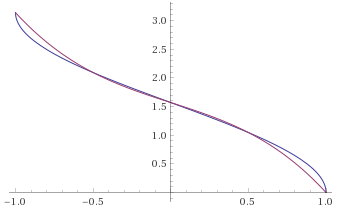
But indeed as @BarsMonster points out this part could be simplified.
PS: I love how this is slowly turning into a "_how did this even work!_" bug :rofl:
CarlosGS
on 15 Apr 2020
The 0.18f is apparently an error bar correction on the approximation, or is at least intended as such. Perhaps a mistake was made here, looking at your plots of both functions.
https://github.com/MarlinFirmware/Marlin/commit/a11eb50a3eab6d58d595a67e526fb51190018db3#diff-e4800bd68f101b55ac4ff95513184458R2139
// Fast acos approximation, minus the error bar to be safe
float junction_theta = (RADIANS(-40) * sq(junction_cos_theta) - RADIANS(50)) * junction_cos_theta + RADIANS(90) - 0.18;
I also noticed this in planner.cpp
// TODO: Technically, the acceleration used in calculation needs to be limited by the minimum of the
// two junctions. However, this shouldn't be a significant problem except in extreme circumstances.
@ejtagle ?
swilkens
on 15 Apr 2020
The function is a perfect approximation... in this region :)

:rofl:
EDIT: It seems this is actually the desired behavior! :exploding_head:
CarlosGS
on 15 Apr 2020
Graphs are very... graphic.
But I believe difference between graphs could not explain the result.
As far as I understand - Intention was to have slower movements for large direction changes, around 45°. If it's not 45, but rather 35 or 55 - that's probably acceptable tolerance.
But in my test part - angular difference between consecutive segments is just a few degrees, it should have never gone as high to trigger this condition even with imperfect approximation. There should be something else going on with small segments. Probably we are loosing resolution somewhere on earlier steps due to very short segments.
Also, I am not sure why short segments should get special treatment. Sharp turns are equally hard for both long and short segments.
BarsMonster
on 15 Apr 2020
I was thinking of the test where you replaced the approximation directly with acos() and fixed things.
The problem is not only tolerance but the general offset that doesn't loop angles correctly.
Could you test again removing the 0.18f and leaving the rest as it was?
CarlosGS
on 15 Apr 2020
The problem of the acos()-approximation is, that its error is largest in the region of interest (>135°). If you drop the -0.18f, the error for theta becomes roughly +10,2°. That is, for 2,75 RAD or theta =157,6°, the uncorrected approximation will give you theta =167.8°. This, in term, reduces (RADIANS(180) - junction_theta) in this line and thereby causes an undesired increase in speed. This speed increase is, what the correction factor avoids.
This -0.18f correction also means, that our cutoff for the correction isn't the 135° in the if-condition, but actually 129,2°. I don't think that this is a problem, though.
An advantage of the current approximation and correction is, that (RADIANS(180) - junction_theta) will never be smaller than 0.18. As we divide by this term, this makes sure our results never "explode".
That being said, I do not see any problem with the acos-approximation other than that it's not very precise. A better acos-approximation would be nice and avoid this clumsy -0.18f-factor, but I don't see how this would be causing the stutter.
XDA-Bam
on 15 Apr 2020
I've looked at the JD_single_arc_test.gcode and computed the segment lengths. The MEAN segment length is 0.60 mm, the MAX is 0.73 and the MIN is 0.09. Here is a plot:
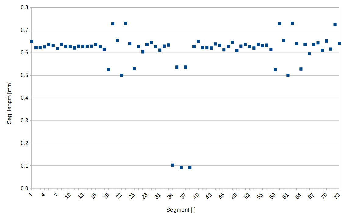
You can clearly see the three tiny segments mid-arc, which is also roughly where you can feel the stutter when printing.
I then went on to estimate the junction speed limit, which is SQRT(limit_sqr) (cmp. limit_sqr). I assumed, that our angle is close to 180°, which means our (RADIANS(180) - junction_theta) is approximately 0.18. This is the best case for speed, as the difference (180-theta) never gets smaller than this. Anything above 175° will be close to identical. Our junction_acceleration is determined in planner.h using the minimum of all axis accelerations which are in motion. As Z and E are not in motion in JD_single_arc_test.gcode, this should - to my understanding - give the minimum of X and Y accelerations. For my printer, that would be 750 mm/s². This results in the following speeds:
| Segment length [mm] | Speed [mm/s] |
| --- | --- |
| 0.73 | 55.1 |
| 0.60 | 50.1 |
| 0.09 | 19.5 |
As you can see, we're more than halving our speed limit for those tiny segments in the arc. Even worse, our limit is jumping up and down a couple of times in quick succession. There is our damn stutter!
XDA-Bam
on 15 Apr 2020
Nice!!! is it then a result of the scaling by block->millimeters? https://github.com/MarlinFirmware/Marlin/issues/17342#issuecomment-613716956
I'm really wondering why @BarsMonster could resolve the stutter by replacing the approximation directly the acos() function :thinking:
CarlosGS
on 15 Apr 2020
Nice!!! is it then a result of the scaling by block->millimeters? #17342 (comment)
I'm really wondering why @BarsMonster could resolve the stutter by replacing the approximation directly the acos() function 🤔
Well, kinda both: Using true acos() means junction_theta can become greater than 2.96, thereby (RADIANS(180) - junction_theta) can get smaller than 0.18 and the speed "explodes", mitigating the issue for angles close to 180°. This is pretty much a race of 1/(angle difference) vs. block length. However, for angles closer to 135°, the block length will still be the issue from my understanding.
Maybe we should look out for a better acos()-approximation AND think about handling the issue with alternating segments of vastly different length.
XDA-Bam
on 15 Apr 2020
Ah!! Thanks so much for detailing the exact cause, no wonder this was driving us crazy :exploding_head:
CarlosGS
on 15 Apr 2020
Looking for a better implementation may take a while - many trigonometry approximations exist.
As an intermediary solution; We might change MIN_STEPS_PER_SEGMENT to be a function of STEPS_PER_MM and a lower limit on the segment length that we decide here. Probably this means increasing the standard value of MIN_STEPS_PER_SEGMENT for the majority of users. This should only be applied when using JUNCTION_DEVIATION obviously.
Pro: Reduce stuttering when using JD, bandage the issue until we find a good fix.
Con: Lose some model accuracy
Alternatively we go back to CLASSIC_JERK for the default while we evaluate this further.
swilkens
on 15 Apr 2020
Quick update: And I also found the reasoning behind the handling of small segments. See this comment.
In short: If you divide a "real" curve into discrete segments, the angle between each segment will be determined by the number of segments. As JD normally only determines the junction speed limit based on this angle, it will go faster around an otherwise identical curve, if it has more segments. Ultimately, it wouldn't slow down at all for curves with an infinite amount of segments. That's not sensible, of course. Therefore, the if (block->millimeters < 1) discrimination was implented as far as I understand.
I think the current if < 1 solution is a good hack for most situations, but obviously, we discovered a couple of problems with it. Thinking about a different approach.
XDA-Bam
on 15 Apr 2020
@swilkens: MIN_STEPS_PER_SEGMENT has to be 1 to get correct prints of fine detail. The current defaul of 6 already produces problems; increasing it is not a suitable fix.
It should be possible to fix the MIN_STEPS_PER_SEGMENT functionality to be non-breaking though. Rather than merging segments based on a small number of quantized steps, it should be merging them based on smallness relative to the (micro)step size and extremely low absolute change in angle between the segments prior to quantization (both conditions met), in which case the tiny segment is almost surely just an artifact of discretizing a curve and not possibly a microstep-scale feature.
richfelker
on 15 Apr 2020
Could you test again removing the 0.18f and leaving the rest as it was?
_I did that and got no noise._ But I also noticed some visible stuttering during brim printing on the first layer. I am trying to investigate what was that and whether it is relevant to this change.
The issue here is that if we make false-negative error in this acos comparison or calculate too high speed - there will also be no noise. So it does not mean that it fixes the issue. It means no stuttering on curves, but might mean faster than intended speed on them.
On acos approximation - while it is possible to compare junction_cos_theta to -0.7071 to avoid any error here, but it would only make comparison more precise, actual speed would still be calculated with error.
This could also explain issues I had with LA, JD and acceleration control #15473 - acceleration control in Cura breaks print moves into small segments with different acceleration, even if it is straight line.
BarsMonster
on 15 Apr 2020
Seems like regardless of whether the approximation is good or not, there should not be any discontinuous behaviors like the hard cutoff here. If the limiting were applied with a continuous window function rather than discrete on/off this kind of stutter shouldn't be possible.
richfelker
on 15 Apr 2020
@richfelker Slicers typically break moves into segments based by this logic - based on deviation and length. it would be hard to rethink quantization behind slicer and avoid any artifacts.
BarsMonster
on 15 Apr 2020
@BarsMonster: I'm aware and know how to configure the slicer not to mess this up. The slicer doesn't do step quantizatiion, just its own merging of segments based on maximum permissible deviation and limits on merged segment length, so the original floating point values are still availble with sufficient precision to distinguish between a 90 degree corner that's 1 microstep wide and an excessive-precision approximation of a curve.
richfelker
on 15 Apr 2020
Im trying to find out approximation of acos. Looks very close, but it uses sqrt, is it feasible?
 daleckystepan
on 15 Apr 2020
daleckystepan
on 15 Apr 2020
Im trying to find out approximation of acos. Looks very close, but it uses sqrt, is it feasible?
There's two close ones using sqrt():
acos = sqrt(2-2*costheta)*pi/sqrt(8) with the possibility to just precalc pi/sqrt(8)=1.11072073
The correction factor pi/sqrt(8)=pi/2/sqrt(2) assures that we reach the same values at pi/2, which is where the sign flip occurs. Otherwise it's identical to your solution, I think. Sign flip has to be handled, as this is only good for [0, 1]. Maximum error +-0.066 rads (Error plot).
Then there's the inverse of the Bhaskara approximation:
pi*sqrt((1-costheta)/(4+costheta))
Same thing with valid range [0, 1] and sign flip. Maximum error is +-0.023 rads (Error plot). This one would be my favourite, if one sqrt() and one divide are acceptable.
EDIT: renamed theta to costheta
XDA-Bam
on 15 Apr 2020
@XDA-Bam Square root and division are 14 clocks each on M4F. Multiplication is 1. So it is relatively slow. On 32-bit CPU without FPU we can expect 10 times more clocks. At 100mm/s printing speed and 0.05mm segments that would mean 560000 clocks per second on updated approximation math, which could be around 1% of low-end STM32. But AVR's will suffer.
But if we compare to -0.7071 and calculate acos only when condition is taken - this would save CPU utilization in average, as corners are suppose to trigger rarely.
BarsMonster
on 15 Apr 2020
Just idea: if we use it only at corners, where the printing speed is lower, it can work.
daleckystepan
on 15 Apr 2020
@XDA-Bam I believe if we use lookup table with some 4-8 ranges, we can get away with fast multiplication only and relatively high precision. I believe we have more flash memory than free CPU cycles. One more note: probably we don't need high precision everywhere, but rather near -1? Update2: We only need to cover range of -1..-0.7071 by approximation, which could significantly simplify the task.
BarsMonster
on 15 Apr 2020
@BarsMonster OK, I'm not used to programming C++ and certainly not on AVRs. If you have some good code for lookup tables in mind, maybe throw it in here? 😄
XDA-Bam
on 15 Apr 2020
@XDA-Bam: Calling the independent variable theta is really misleading/confusing...
richfelker
on 15 Apr 2020
I've been taking a deeper look at the JD_single_arc_test.gcode. I've calculated equivalent radii and resulting junction speeds for a=750 mm/s². For the critical region with stutter, the result is the following (EDIT: velocities are about twice as high as in Marlin, because my spreadsheet uses precise arccos()):
Seg. length | Junc. angle (to _prev._) | Equiv. radius | V_max junction
-- | -- | -- | --
0.6291 | 177.47 | 14.2 | 103.278
0.6335 | 177.53 | 14.7 | 105.066
0.1025 | 176.79 | 1.8 ⏬ | 37.050
0.5363 | 179.28 | 42.8 ⏫ | 179.243
0.0911 | 176.83 | 1.6 ⏬ | 35.142
0.5362 | 179.30 | 43.6 ⏫| 180.831
0.0910 | 176.78 | 1.6 ⏬ | 34.852
0.6271 | 179.53 | 77.0 ⏫ | 240.261
The actual radius is 14.375 mm, so most estimates are reasonably close. What is odd, though, is that on the very short segments, _both_ segment length _and_ junction angle drop. The following junction angle is then longer. This difference of +-1.5° is very important here. The angle in my spreadsheet is calculated backwards, like in the code.
If I now switch to forward calculating the junction angle, the slightly increased junction angle always falls in line with the short segments:
Seg. length | Junc. angle (to _next_) | Equiv. radius | V_max junction
-- | -- | -- | --
0.6291 | 177.53 | 14.6 | 104.706
0.6335 | 176.79 | 11.3 🔽 | 92.112
0.1025 | 179.28 | 8.2 🔽 | 78.360
0.5363 | 176.83 | 9.7 🔽| 85.244
0.0911 | 179.30 | 7.4 🔽 | 74.551
0.5362 | 176.78 | 9.5 🔽 | 84.598
0.0910 | 179.53 | 11.2 🔽 | 91.526
0.6271 | 177.23 | 13.0 | 98.579
And would you look at that: The speed and radius dips are nearly gone! And they are all in one direction now, no more harsh ups and downs. There is still a max dip of about 25% in speed, but not +71/-66% anymore, as before.
Question therefore, for anybody knowing the code well: Why are we calculating the junction angle backwards and not forward?
EDIT: Important typo in header of second table corrected.
XDA-Bam
on 15 Apr 2020
@XDA-Bam: Calling the independent variable
thetais really misleading/confusing...
True. Changed.
XDA-Bam
on 15 Apr 2020
I've found a MinMax polynomial here, which reaches a maximum error of +-0.033 rads (error plot) using only multiplications.
acos(x) = π * 0.5f
  - (0.032843707f
      + x * (-1.451838349f
      + x * (29.66153956f
      + x * (-131.1123477f
      + x * (262.8130562f
      + x * (-242.7199627f
      + x * (84.31466202f
    )))))))
Again with valid range [0, 1] and requiring handling of sign flip.
@BarsMonster Would this be faster than sqrt+divide?
XDA-Bam
on 15 Apr 2020
I haven't looked deep into the JD code since the last overhaul, but I seem to remember something concerning tight corners with very small segments, which are actually very fast turns, but which either classic jerk or JD would only see as slight turns and so wouldn't slow down properly. I might be remembering wrongly, or that might have been discussed and dismissed.
Anyway, I'm happy to see a better acos approximation being explored as a solution. Anything which is faster than the SQRT is perfectly acceptable. The planner code is all run in user context so if the maths are performed as double on ARMs that have FP acceleration the speed should be very fast.
thinkyhead
on 16 Apr 2020
@thinkyhead Yes, the problem of the main JD code is, that the junction angle shrinks, if the number of segments on a curve increases. See this comment on the original issue and resulting mitigation.
However, replacing the current acos() approximation will only _mitigate_ the stuttering issue somewhat for angles above 169.69° (that'S pi-0.18f rads). This will be a good first step. But as detailed in my comment from yesterday, there seems to be an issue with the way the junction angle is currently computed: We are computing it "backwards" to the last element, which seems to introduce strong oscillations in limit_sqr. This is, in my opinion, the main cause of the stutter. If we switch to compute the junction angle forwards, this seems to solve the problem. What's your opinion on such a change?
XDA-Bam
on 16 Apr 2020
Sorry i don't understand. What is forward? What is backward?
The junctions speed we want to calculate depends an the angle between segment a (coming from) and segment b (going to). That should not depend on if we take the angle between (a and b) or between (b and a).
If any other segment is involved - that's an error.
the slightly increased junction angle always falls in line with the short segments:
That's impossible. The angle is always in between of two segments. Only in a spreadsheet the values may appear on the one or on the other line.
The planner code is all run in user context so if the maths are performed as double on ARMs that have FP acceleration the speed should be very fast.
The F3s (and DUE) don't have an Floating Point Unit (FPU) - only the F4s have, and that can only handle _floats_ directly, not _doubles_. However - on the ARMs the code, however it looks, will likely be fast enough. Not so at the AVRs. (For good reason we should always use the 1.F-notation to not accidentally use double constants. Except we really want doubles for the exactness. Usually we don't need that. (The F4s are usually compiled with a compiler option like USE_FLOAT_CONSTANTS - but for the F3s it matters. The AVRs always calculate in float only. I have no idea how the ESPs might handle this.))
As far as i remember acos() is implemented as a lookup table with interpolation for the most processors floating point libraries even for that with FPUs - at least it is not a hardware instruction. A benchmark against the library is mandatory for any wannabe faster approximation (for all relevant platforms and processor architectures (AVR, ARM32 with and without FPU))
 AnHardt
on 16 Apr 2020
AnHardt
on 16 Apr 2020
Sorry i don't understand. What is forward? What is backward?
Sorry, that may have been unclear.
- Backward: Calculating the junction angle as the angle to the preceding segment.
- Forward: Calculating the junction angle as the angle to the following segment.
The junctions speed we want to calculate depends an the angle between segment a (coming from) and segment b (going to). That should not depend on if we take the angle between (a and b) or between (b and a).
If any other segment is involved - that's an error.
It looks to me, like the Marlin planner always operates segment by segment. Per segment, there is only one junction angle being calculated. I would therefore consider each angle to be more or less "attached" to a specific segment. As it is now, as far as I understand the code, the junction angle is defined as the angle between the segment currently being planned and the preceding segment. I hope this clarifies my train of thought.
Just out of curiosity, I've tested what happens if we define the junction angle as angle from the current segment to the following segment. That's what my second table shows. This definitely eliminates the stuttering. I am not sure though, if this change in the definition of the junction angle makes sense in the context of Marlin code. That's why I'm asking.
the slightly increased junction angle always falls in line with the short segments:
That's impossible. The angle is always in between of two segments. Only in a spreadsheet the values may appear on the one or on the other line.
This is a bit splitting hairs now. But yes. Nonetheless, each segment has exactly one corresponding junction angle in Marlin: The one to the preceding segment. That's what I meant by "falls in line with short segments". In the current code, the slightly smaller junction angles are calculated when the code is looking at the unusually short segments. This amplifies the stuttering problem.
The planner code is all run in user context so if the maths are performed as double on ARMs that have FP acceleration the speed should be very fast.
The F3s (and DUE) don't have an Floating Point Unit (FPU) - only the F4s have, and that can only handle _floats_ directly, not _doubles_. However - on the ARMs the code, however it looks, will likely be fast enough. Not so at the AVRs. (For good reason we should always use the 1.F-notation to not accidentally use double constants. Except we really want doubles for the exactness. Usually we don't need that. (The F4s are usually compiled with a compiler option like USE_FLOAT_CONSTANTS - but for the F3s it matters. The AVRs always calculate in float only. I have no idea how the ESPs might handle this.))
As far as i remember
acos()is implemented as a lookup table with interpolation for the most processors floating point libraries even for that with FPUs - at least it is not a hardware instruction. A benchmark against the library is mandatory for any wannabe faster approximation (for all relevant platforms and processor architectures (AVR, ARM32 with and without FPU))
I would expect a default library implementation to be fast. Nonetheless, the consensus in this thread up to this point seemed to be, that native/library acos() may be too slow to use for JD on some architectures. I have no idea of how fast or slow it actually is and I have no means of testing it myself. I hope someone can either provide some hard numbers, or do a quick test.
I have created a PR with the MinMax polynomial mentioned earlier. It runs fine on my ATMega1284, as far as I've tested it. If the default library acos() is even faster: Perfect. Let's use that. If not, the MinMax will do, I think. Should be easy to test using that PR. In any case, I am certain that we need the increased precision close to cos(180°) to mitigate the stuttering.
XDA-Bam
on 16 Apr 2020
I would expect a default library implementation to be fast.
This is an incorrect expectation. The standard math library is there to give correct results, not fast approximations. There are countless different ways to do fast approximations, most of them simple, and all of them tuned to particular uses, so it doesn't make sense for them to be part of any standard library; you just write out the one that makes sense for what you need to do. The hard task that programmers can't be expected to do per-program is making a version that's accurate across the entire domain.
richfelker
on 16 Apr 2020
Marlin plans always exactly one planer-buffer-line, the new line, the last line. This segment always stops at zero speed. There is no knowledge about what move could come next or if there will be a next move. So the only junction that can be calculated is the one to the previous line segment. So the junction speed is the highest allowed entry speed for the currently planed segment.
In a second phase of the planing process forward/backward/recalculate-path (optimizer) we try to rise the exit speed of the previous segment (what is still zero) to the entry speed of the new segment, if possible (the last segment must be able to decelerate to zero).
The planer calculates the max. target speed, the max. de/accelerations und the max. entry speed for each segment depending on the involved axes and the settings plus the number of steps for each axis and determines the leading axis (with the most steps). The optimizer determines at what step-number (of the leading axis) the acceleration phase ends and the deceleration phase begins - trying to reach the maximum speed determined by the planing process. It is revisiting all but the currently stepped and the already maximized lines in the planner buffer.
AnHardt
on 16 Apr 2020
Thank you for explaining this in detail, @AnHardt
I have also realized that calculating the junction angle to the following segment - while impossible anyway, with the current code - would also only mask the stutter problem for our specific test file JD_single_arc_test.gcode. If, in another GCode, the slicer decided to distribute the slightly smaller than average angles differently onto the tiny segments, we would have the same problem again. It's inherent to the discretization and there is no "error" in the code in that sense.
It still bugs me, that we see this sawtooth/stutter in limit_sqr. Would it be feasible to replace block->millimeters in the small segment hack with _an average of the lengths of the current and preceding block_? That would be geometrically bulls*, but it will act as a low-cost lowpass and smooth out the stutter. Would that be acceptable?
XDA-Bam
on 16 Apr 2020
Thinking about the problem of junction speed naively…
On the one hand, when you have a Y-bed and an X-carriage that are each on different motors and linear rails, the torque is actually de-coupled between the two axes. So adjusting the speed based on changes of angle is unwarranted. For this reason, in a typical Mendel machine the better choice is Classic Jerk. (CAMB.)
Anyway, when you do want to consider the change in angle in a situation with small segments, you need a trick to be able to examine more of those segments (besides having a huge planner buffer) and to be able to determine that an obtuse change in angle is occurring. Which is to say, a way to "accumulate deceleration" where you're weighting the change in angle in inverse proportion to the amount of time elapsed since the last angular change.
One way to approach this would be to maintain a "change in angle over time" accumulator which starts out at zero, and you can think of it as pointed in the direction that the inertial mass is moving. In circumstances where no deceleration is needed, this value will stay close to zero — or at least below the deceleration threshold.
When there's a change in angle between segments, the amount of angular change (off-axis torque) is weighted by the inverse length (inverse duration) of the segment. If enough change in angle accumulates then a certain amount of deceleration is applied.
Meanwhile, over time you are also subtracting a certain amount from this accumulator, so that it takes a lot of angular change over a small period of time before it goes over its threshold. A perfect 90 degree turn spaced over ten very short segments might be the most obvious case where you would need to slow down to zero but the current planner might miss that completely and only slow down by half….
It bears some experimentation to see if an accumulator-plus-threshold approach could work.
thinkyhead
on 19 Apr 2020
Another thought is, if the original acos approximation wasn't great, and the new one also isn't great, maybe averaging the two together will be less than worse.
junction_theta = RADIANS(90)
  + ((t * (sq(t) * RADIANS(-40) - RADIANS(50)) - 0.18f) - (neg * asinx)) / 2;
…Optimizing out the extra operations…
const float
  neg = junction_cos_theta < 0 ? -1 : 1,
  t = neg * junction_cos_theta,
  asinx =       (0.032843707f / 2)
        + t * (-(1.451838349f / 2)
        + t * ( (29.66153956f / 2)
        + t * (-(131.1123477f / 2)
        + t * ( (262.8130562f / 2)
        + t * (-(242.7199627f / 2) + t * (84.31466202f / 2) ) )))),
  junction_theta = RADIANS(90) - (neg * asinx)
    + (t * (sq(t) * (RADIANS(-40) / 2) - (RADIANS(50) / 2)) - (0.18f / 2));
From my benchmark in #17575 i'd say.
1/3 + 2/3 = 3/3. Means - if you can't considerably speed up the calculation of averaging the both approximations - take the original fp-libraries acos() function - that's, at least, exact.
AnHardt
on 19 Apr 2020
The new acos() is pretty good, but it's not super fast. Averaging with the old will drastically reduce precison in the critical region close to 180°, where the old approx was bad. Plus it's slower as @AnHardt pointed out. So, averaging these two correlations has mostly downsides. It may be workable with totally different equations, but we would have to find those first. I like the idea of @BarsMonster to just "divide and conquer" multiple ranges seperately. Maybe this can also offer an advantage in calculaction time.
That being said, the acos() is better already, which eliminated the problem for most prints. And it will probably be improved even further. The main problem with short segments and 'unlucky' angles still holds. I like the idea of an accumulator approach for the change in angle. I will explore it a little more.
XDA-Bam
on 19 Apr 2020
I like the idea of an accumulator approach for the change in angle. I will explore it a little more.
Yeah, me too. I only have a vague idea how it would work, but it will need lots of tuning to find the right balance of accumulator "heating and cooling" on those angular changes.
take the original fp-libraries acos() function - that's, at least, exact.
If only we could find our own "what the fuck?" for acos like there is for the fast inv sqrt.
float Q_rsqrt(float number) {
  long i;
  float x2, y;
  const float threehalfs = 1.5F;
  x2 = number * 0.5F;
  y  = number;
  i  = * ( long * ) &y;                       // evil floating point bit level hacking
  i  = 0x5f3759df - ( i >> 1 );               // what the fuck?
  y  = * ( float * ) &i;
  y  = y * ( threehalfs - ( x2 * y * y ) );   // 1st iteration
  //y  = y * ( threehalfs - ( x2 * y * y ) ); // 2nd iteration, this can be removed
  return y;
}
I have tinkered a bit with different ideas concerning the accumulator and have put together a little test script in MATLAB/Octave. I will present you a couple results.
Current state
Let's first take a look at our beloved JD_single_arc_test.gcode, which is the half circle outer wall on this part (starting point marked with red arrow):
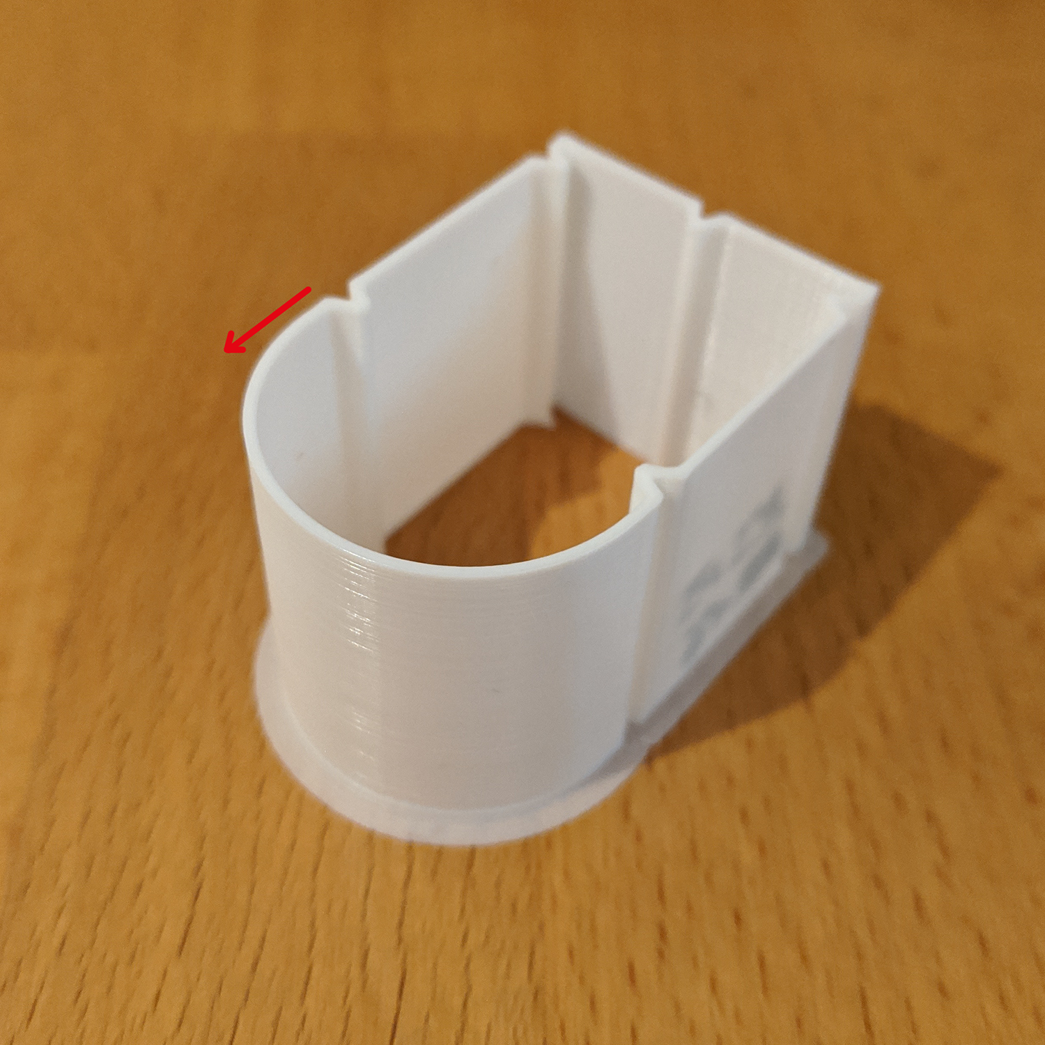
On this curve, the current limit speed profile in Marlin should look like this (LOG scaling on Y-axis!):

What is what:
- The red curve is the "default" junction deviation
v_max_junctionand can never be exceeded. - The yellow curve is the additional
limitfor segments < 1 mm with junction angles above >135°. - The light grey area in the background (which does not cover the whole graph!) is the area, where the
< 1 mm & >135°code path is used.
Keep in mind, that the planner could choose lower speeds for the segments, for example because the acceleration is too low to reach the speed limit given in the plot. Also, the print head/planner accelerate and decelerate, which is also not shown in the plot. The plot only shows speed limits.
Possible solution
The idea was, to somehow avoid those dips at the 20 mm mark. @thinkyhead suggested some form of "accumulator", which takes into account the change rate of junction_theta. After a lot of tinkering, I have build an exponentially decaying delta_angle_indicator, which roughly tells us, how much our junction angle is changing per mm of travelled length. The main code looks like this:
[MATLAB pseudocode]
delta_angle_indicator = delta_angle_indicator * max(0, 1 - delta_angle_decay ...
                         * block_millimeters) + abs(delta_theta)) * inverse_millimeters;
The indicator starts out at 0 and grows, if the junction angle changes. It constantly shrinks/decays, depending on how far we travel. The term (1 - delta_angle_decay * block_millimeters) makes delta_angle_indicator somewhat independent of block length, without requiring the use of powers or logarithms. To understand the indicator, we also need to know the following variables:
delta_theta = rad2deg(junction_theta - previous_junction_theta);
=> delta_theta [°] describes the change in junction angle to previous block.
delta_angle_threshold = 2.5e-1;
=> delta_angle_threshold [°/mm] is our "act now threshold". If delta_angle_indicator > delta_angle_threshold, we are in some sort of curve and should probably reduce speed.
delta_angle_decay = 1.0;
=> delta_angle_decay [1/mm] determines the fractional reduction of the delta_angle_indicator per mm traveled. A value of 1 means, that our indicator should be back to zero after 1 mm if no further curves come up.
Now that we have a measure of the angular gradient per mm, we can think about how to react to it. I have tried various ways of making it scale nice between limit_sqr and vmax_junction_sqr and other ideas. But in the end, the exponential decay makes that very difficult, because the indicator spans a couple of orders of magnitude. What has proven more useful is the following approach:
[MATLAB pseudocode]
if delta_angle_indicator > delta_angle_threshold
  % The angle is changing fast and we should update limit_sqr to make sure our limit is low enough.
  limit_sqr = block_millimeters ./ (deg2rad(180) - junction_theta) .* junction_acceleration;
else
  % Not much going on with the angle. We can keep going fast.
  limit_sqr = max( block_millimeters ./ (deg2rad(180) - junction_theta(i)) .* junction_acceleration, ...
                       previous_limit_sqr );
end
Essentially, limit_sqr is in effect as before if the junction angle is changing too fast. If it's changing slowly or not at all, we just "coast" and keep the speed constant. And that's all. The resulting speed graph looks like this (LOG scaling again):
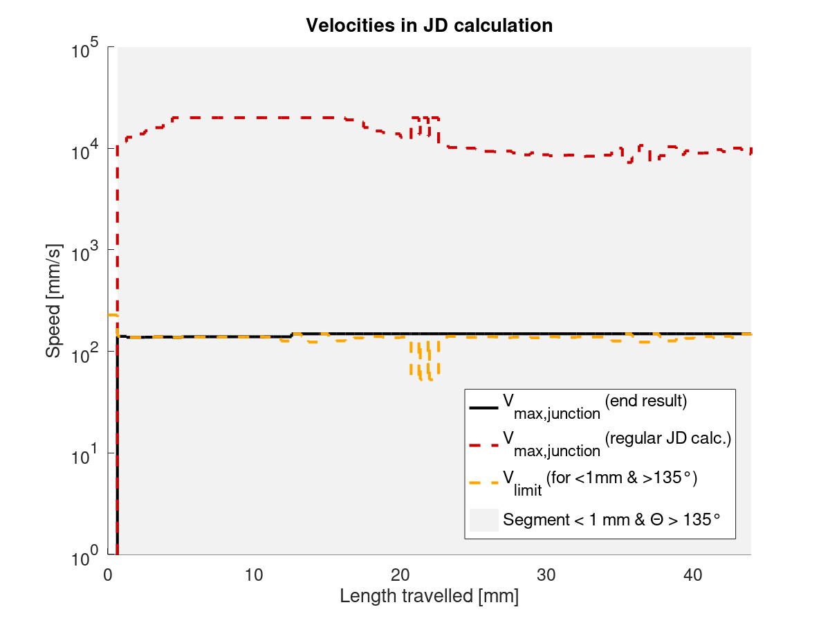
You can see that - with the values for delta_angle_threshold and delta_angle_decay chosen here - we pretty keep the speed constant, except for a small bump up after about 12 mm or so.
Conclusion
This is the current state of development. There is no C++ code, yet and this hans't run on any printer. Also, delta_angle_threshold and delta_angle_decay might be tricky to tune in practice. But I'm putting this up for discussion here. Comments welcome.
NOTE: I'm gonna write a second post with graphs for a different example file shortly.
XDA-Bam
on 22 Apr 2020
OK, here comes the second GCode I tested. The part looks like this (again, starting point and print direction marked by red arrow):

Current state
The speed limit profile with upstream Marlin for a single outer wall on this part should look like this:
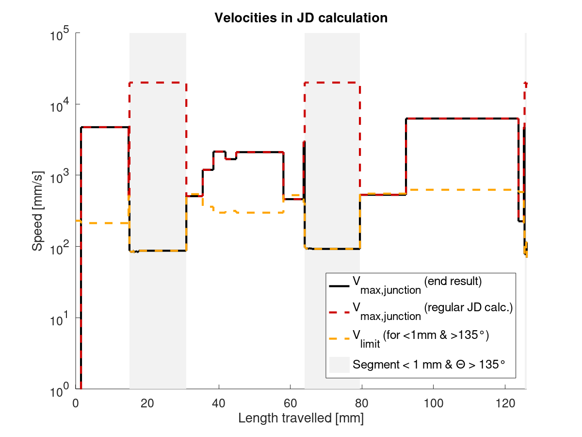
Notice that the grey areas, where our < 1 mm & > 135° code path is active are much smaller here. These are also the only regions, where the proposed solution would intervent.
Proposed solution
Using the delta_angle_indicator with the same settings as in my last post, the speed limit profile looks like this:

Notice that there isn't many differences. In fact, with the exception of the region around 70 mm, the profiles are identical. And they probably should be, because there's a lot of sharp corners and large changes in the junction angle on this part, so it's a good thing we're not speeding through those.
And just for fun, here's a plot of the actual indicator, corresponding to the above speed limit graph:
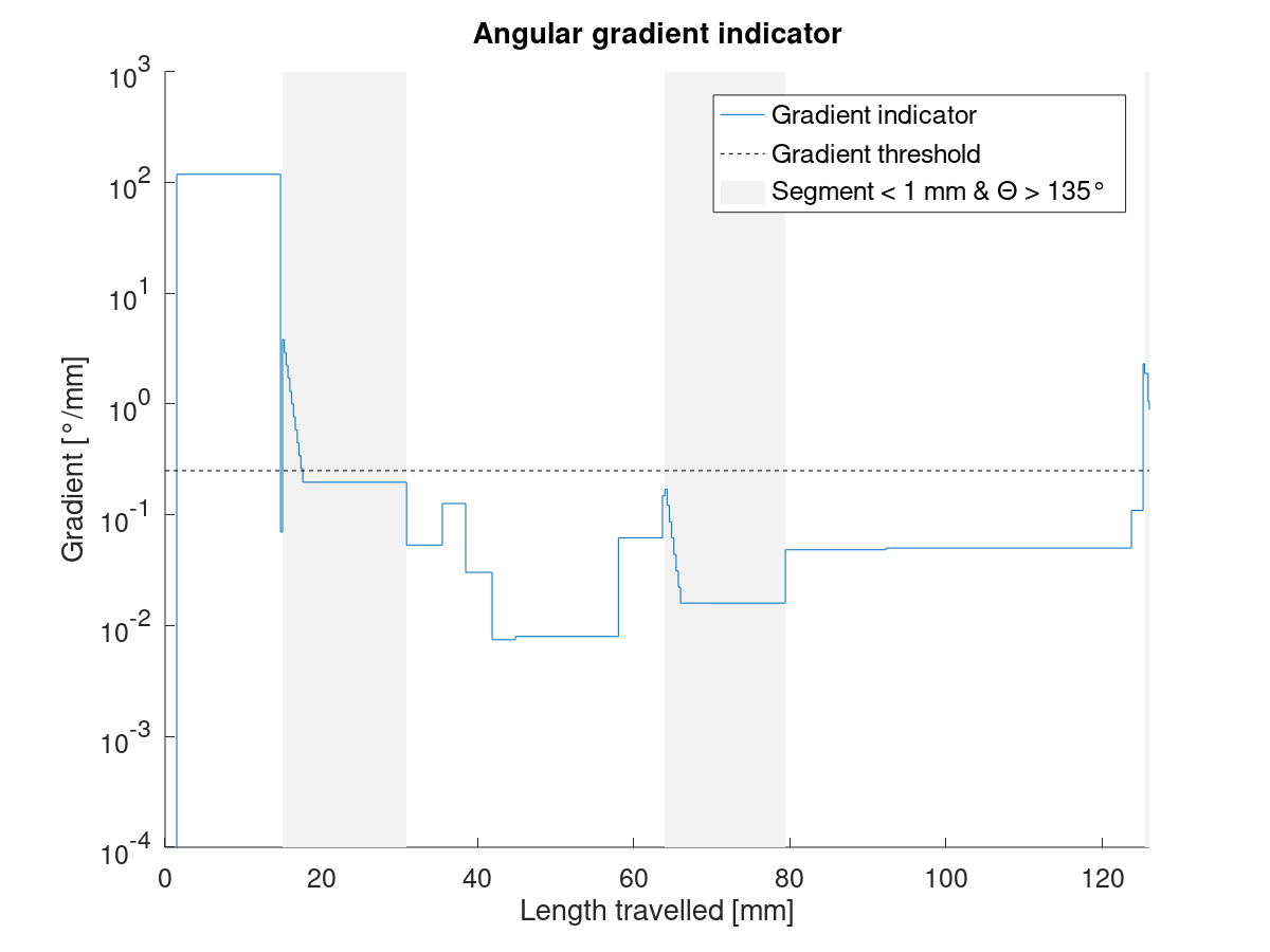
I'm not quite sure what to make of all this, yet. First results look kinda promising, but it might still fail in practice. The indicator is very dynamic and even small changes in the part or slicer settings could have a big impact on the resulting speed profile. We will see.
XDA-Bam
on 22 Apr 2020
It does look promising! And it has me contemplating the fundamentals…
I'd be interested to see some comparison of a square box aligned to the bed versus a square box that is 45° to the bed. On a Mendel you should be able to draw a zigzag from left-to-right without slowing much. But a "square wave" line on a Mendel has to stop at each corner. From the JD perspective do these look the same? They both do 90° turns.
Another thing occurred to me just now…
Tiny (last) segments might come out of the planner segmenter for delta and leveling, and those tiny segments could cause issues, so I want to do a quick sweep to make sure the last two segments of any segmented line are (segment_size + last_len) / 2.
thinkyhead
on 24 Apr 2020
Thinking it over more, I see the jerk problem more simply, as one of changing direction from one forward speed to some reverse speed, where more flat angles are less jerky in all cases, and more pointy angles are more jerky in all cases.
It seems like it would be fruitful to look at the accumulator method across all angular changes and at all segment lengths, with accumulation and slowdown on any angular change at all. So, you add on the "amount of momentum that the angular change is transferring to the frame," subtract the amount that the frame can absorb, and slow down by the percentage required to take up the difference.
I could be wrong but I think that if you slow down by (up to) double the amount that you think you're deflecting in the turn, it will actually cancel out all the ringing.
thinkyhead
on 24 Apr 2020
Because the physical acceleration/jerk limitations depend highly on the mechanics of the machine (straight cartesian vs corexy vs delta ...) I think the junction deviation model of doing the limits in cartesian print space is just wrong; the classic jerk model is right. Classic jerk does have a lot of fundamental bugs, like how it can accumulate over many small segments and allow moves that exceed the physical capabilities of the machine, but those could and should be solved by the sort of "accumulation over time with decay" approach proposed above for JD, only the accumulations are a lot simpler when they're in motor-axis space (no angles involved).
richfelker
on 24 Apr 2020
Agreed. But it still leaves the error in both approaches when you have many very small segments in a 90° turn and the planner only sees 18° of the curve at any one time.
thinkyhead
on 24 Apr 2020
…I suppose the scaling of the angular change to segment time might be hitting some edge. An 18° change in 1ms might not scale linearly to an 18° change in 10ms or 100ms….
thinkyhead
on 24 Apr 2020
From some standpoint, the angle is irrelevant. The only real change is change in desired velocity individually along each motor axis. However I probably went too far in saying that JD is completely wrong, since the mass of the print head does move in cartesian space, and decelerations along one motor axis may put energy into assisting with an acceleration along a different one.
Anyway, whether you have a 90° turn as a single corner or spread over a few super-tiny segments, you still see the same accumulated-and-decayed change of velocity along each axis over a time window bounded away from zero.
richfelker
on 24 Apr 2020
Yeah, in my mental review today I realized that working in vector space will produce results consistent from working in Cartesian space. But, you are correct that Jerk has the ability to consider the mass / inertia / momentum of the carriage and bed individually and to consider (indirectly) how much momentum is being imparted by each axis.
I am imagining a synthesis of the two approaches, so that the X (carriage) mass component can be weighted more or less than the Y (bed) mass component. Ideally, it would be good to model everything in terms of the physical properties and then simplify, but a lot of what we have today came from just that process. Re-unpacking all the optimized code would be a good exercise to find places where things might be optimized.
thinkyhead
on 24 Apr 2020
Speaking of which… Since we only use the following junction_theta result when it is in a certain range, I wonder if the asinx approximation can be only partially evaluated and then the rest can be evaluated only when it could result in theta>135. I'll have to put it into my graphing calculator….
const float neg = junction_cos_theta < 0 ? -1 : 1,
            t = neg * junction_cos_theta,
            asinx =       0.032843707f
                  + t * (-1.451838349f
                  + t * ( 29.66153956f
                  + t * (-131.1123477f
                  + t * ( 262.8130562f
                  + t * (-242.7199627f
                  + t * ( 84.31466202f )))))),
            junction_theta = RADIANS(90) - neg * asinx;

if (junction_theta > RADIANS(135)) { ... }
One tiny optimization: Deriving acos(-t) instead of acos(t) to eliminate one subtract operation. #17684
thinkyhead
on 24 Apr 2020
When having different "jerk-speeds" for the axes the "JD-circle" transforms to an "ellipse". Challenging math ahead.
AnHardt
on 24 Apr 2020
I agree that the base model being in cartesian space is a problem. I haven't looked at the jerk code, but for JD, it's only really correct for cartesian machines. I think if you break down the mechanics and leave out the extruder for now (which I think should be handled in a seperate loop/environment), theres seven elements in motion:
- Three stepper motors SA, SB and SC
- Three frame parts FA, FB and FC
- The print head P
Each of those parts has acceleration and jerk (in the physical sense -> da/dt) limits, above which they either - in case of the motors - lose steps, or the forces just become too high causing problems in the print. Currently, we don't have those fourteen seperate limits - seven for accel., seven for jerk - but I think we do need them.
Our print data and all calculations happen in cartesian space along the X, Y and Z axis. If you now look at the acceleration or jerk limits of the parts, they are interconnected in different ways depending on the machine geometry:
- For a cartesian machine, motor SA and frame part FA are interconnected ("X axis"), as are motor SB and frame part FB ("Y axis") and so on. The print head is typically interconnected with FA and FC (X and Z axis), SA and SC (X and Z steppers). Any acceleration limit applying to motor SA (the X axis stepper), for example, also applies to frame part FA (the X axis frame) and vice versa. So for moves in the X direction of the Marlin coordinate system, the lowest of the three acceeration limits for SA, FA and P has to be respected. The same logic applies to jerk limits.
- For a delta machine, neither of the frame or stepper movements are aligned to the cartesian Marlin coordinate system. So for moves in the X plane, we have to respect the lowest of all seven acceleration and seven jerk limits for each movement: Those of each moving frame part FA-FC, those of the three steppers SA-SC and the limits of the head P.
- For a CoreXY machine, it's different again. Steppers SA and SB are both responsible for movements in the X direction of Marlin's corrdinate system. Further, the acceleration and jerk limits of frame part FA and the print head P also apply in the X direction. And so on, and so forth.
So, if you want to think about redesigning jerk and/or JD from the ground up, I think we first need to decouple all acceleration and jerk limits from the X, Y and Z axis and redefine 'em for the seven main moving parts. We may be able to ignore the print head P, as it's effectively limited by at least one frame part on any printer I can imagine. But other than that, I don't think three limits in X/Y/Z are enough to model a printer correctly.
XDA-Bam
on 24 Apr 2020
Also: I have this delta_angle_indicator thing running on my printer. It didn't expode (yet). You want me to PR this into bugfix-2.0.x for testing? Or is this rather something for dev-2.1.x?
XDA-Bam
on 24 Apr 2020
@XDA-Bam — Yes, please. We need all the good testing pieces we can get in the area of motion and planner analysis. I've been playing with the calculations over at https://www.desmos.com/calculator/pg3q7fh1ja
thinkyhead
on 24 Apr 2020
I noticed that (according to the graph) whenever the input value to the arcsine approximation is greater than 0.7071067812 the junction_theta value goes out of range in the junction_theta < RADIANS(45) test. So there is no need to do the formula for input values over 0.7071067812.
Please correct me if I am misinterpreting something in the result.
thinkyhead
on 24 Apr 2020
Maybe I'm missing something (I haven't read the code) but if you want to compare an angle against a fixed value, why would you compute acos to get the angle rather than just comparing x against cos of the reference (135 or whatever)? There might be some domain issues but at worst it should be a few interval tests...
richfelker
on 24 Apr 2020
You can compare cos_junction_theta against the known cos(135) for the if condition, but you still need junction_theta to calculate limit_sqr. Or are you talking about a different line?
EDIT: And yes, that means you can calculate junction theta AFTER the if (junction_theta > RADIANS(135)) {, if you check against junction_cos_theta instead.
XDA-Bam
on 24 Apr 2020
@thinkyhead "Yes, please" bugfix-2.0.x or "Yes, please" dev-2.1.x ? :D
XDA-Bam
on 25 Apr 2020
Please submit to bugfix-2.0.x That will be easiest to keep in sync during testing.
thinkyhead
on 25 Apr 2020
The graph says this is probably correct…
const float neg = junction_cos_theta < 0 ? -1 : 1,
              t = neg * junction_cos_theta;

// Only under sin(-45°) [== cos(135)] can the final result be under 45°
if (t < -0.7071067812f) {
  const float asinx =       0.032843707f
                    + t * (-1.451838349f
                    + t * ( 29.66153956f
                    + t * (-131.1123477f
                    + t * ( 262.8130562f
                    + t * (-242.7199627f
                    + t * ( 84.31466202f ) ))))),
              junction_theta = RADIANS(90) + neg * asinx; // acos(-t)

  // If angle is under 45 degrees (octagon), find speed for approximate arc
  if (junction_theta < RADIANS(45)) {
    // NOTE: MinMax acos(-x) approximation (junction_theta) bottoms out at 0.033 which avoids divide by 0.
    const float limit_sqr = (block->millimeters * junction_acceleration) / junction_theta;
    NOMORE(vmax_junction_sqr, limit_sqr);
  }
}
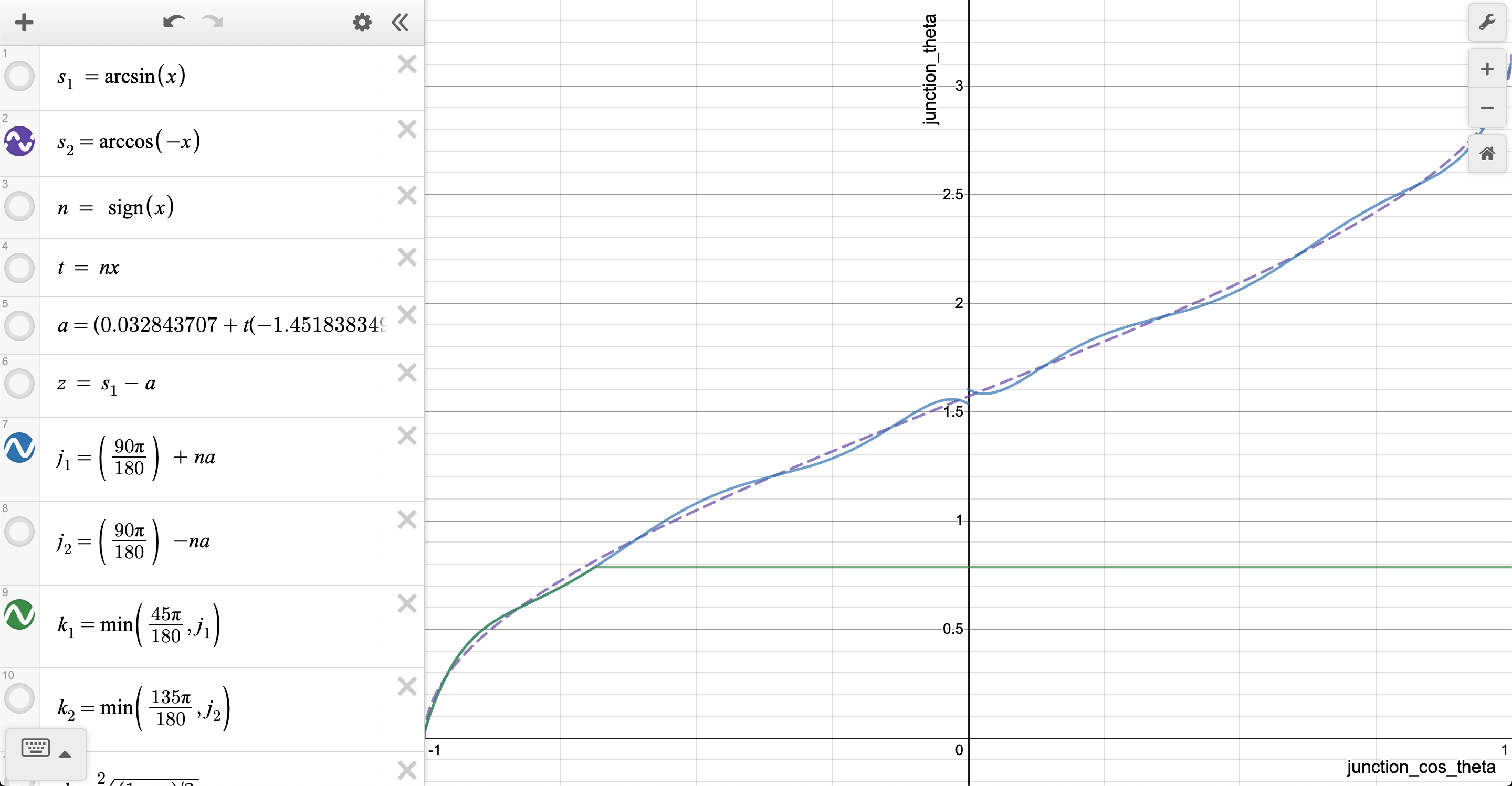
thinkyhead
on 25 Apr 2020
Concerning the PR: OK, will do.
Concerning your code snippet: Why check against t and junction_theta? Except for a small numerical error, this will give the same result. Why not go
if (junction_cos_theta < -0.7071067812f) { // -1/sqrt(2) equiv. to 135°
  const float t  = -junction_cos_theta,
  junction_theta = RADIANS(90)
                    +       0.032843707f
                    + t * (-1.451838349f
                    + t * ( 29.66153956f
                    + t * (-131.1123477f
                    + t * ( 262.8130562f
                    + t * (-242.7199627f
                    + t * ( 84.31466202f ) )))));

  const float limit_sqr = (block->millimeters * junction_acceleration) / (RADIANS(180) - junction_theta);
  NOMORE(vmax_junction_sqr, limit_sqr);
}
By checking against junction_cos_theta, there is no ambiguity. It's smaller than -1/sqrt(2) for angles above 135°.
XDA-Bam
on 25 Apr 2020
The domain where we're calculating the slowdown is small enough that it could be reduced to some simple curve fits, and then the 6 or more multiplications won't be needed either. Just one subtract and one multiply…
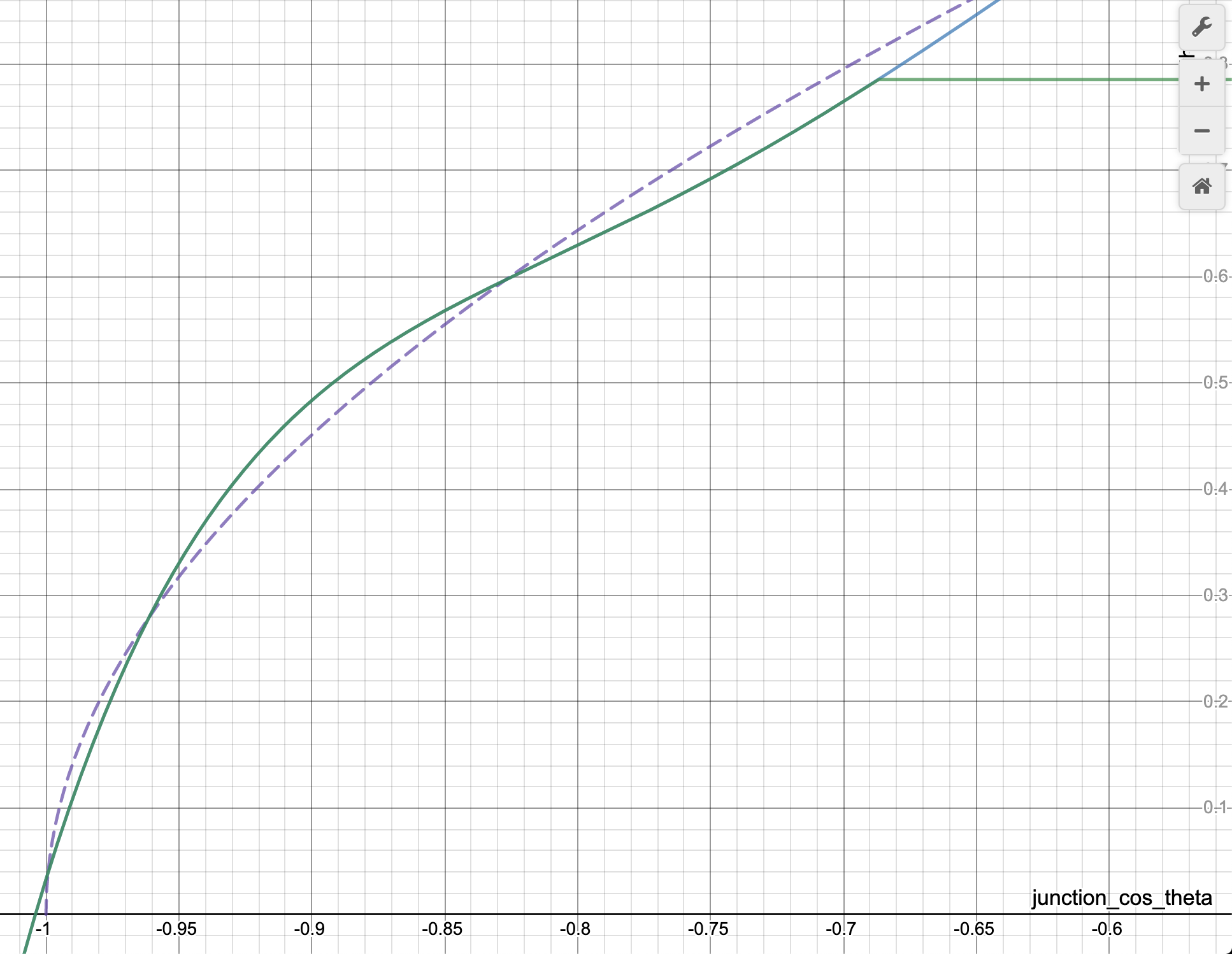
thinkyhead
on 25 Apr 2020
Between the values of -1/sqrt(2) and -0.85 this formula is close enough to the real arccos result to be useful:
acos_minus_t = 0.785f + 1.6f * (q + 0.7071067812f);
Here's a pretty good approximation with not too much error…
const float neg = junction_cos_theta < 0 ? -1 : 1,
              t = neg * junction_cos_theta;
// Only under sin(-45°) can the final result be under 45°
if (t < -0.7071067812f) {
  junction_theta =
      (t >= -0.85f) ? 0.7850f  + (t + 0.7071067812f)
    : (t >= -0.89f) ? 0.5550f  + (t + 0.85f) *  2
    : (t >= -0.93f) ? 0.4750f  + (t + 0.89f) *  2.46f
    : (t >= -0.97f) ? 0.3766f  + (t + 0.93f) *  3.275f
    : (t >= -0.98f) ? 0.2456f  + (t + 0.97f) *  4.527f
    : (t >= -0.99f) ? 0.20033f + (t + 0.98f) *  5.879f
                    : 0.14154f + (t + 0.99f) * 14.154f;
  const float limit_sqr = (block->millimeters * junction_acceleration) / junction_theta;
  NOMORE(vmax_junction_sqr, limit_sqr);
}
I assume the compiler is smart enough to bisect the test ranges so it can do 4 compares instead of 6, but it could be made explicit, sort of like this…
junction_theta =
  (t >= -0.93f) ?
      ( (t >= -0.85f) ? 0.7850f  + (t + 0.7071067812f)
      : (t >= -0.89f) ? 0.5550f  + (t + 0.85f) * 2
                      : 0.4750f  + (t + 0.89f) * 2.46f )
  : (t >= -0.98f) ?
      ( (t >= -0.97f) ? 0.3766f  + (t + 0.93f) * 3.275f
                      : 0.2456f  + (t + 0.97f) * 4.527f )
    : ( (t >= -0.99f) ? 0.20033f + (t + 0.98f) * 5.879f
                      : 0.14154f + (t + 0.99f) * 14.154f );
You can probably even kill the branches and convert it to a table lookup (for which additive and multiplicative constants to use) based on a few bits of the float representation, if that helps.
richfelker
on 25 Apr 2020
Embodiment in code tends to be faster in these processors, but a LUT is worth testing. The other question is whether float compare always incurs a subtract, or whether it uses binary compare tricks.
thinkyhead
on 25 Apr 2020
My C++ skills aren't very good, but t = neg * junction_cos_theta; should always be positive, right? Seeing that all compares are set up for negative values of t, and all equations also only work for t<0, that doesn't look right. First line should be const float neg = junction_cos_theta > 0 ? -1 : 1,, or am I reading that wrong?
Also, the error of this approach is skyrocketing for values in between the grid points. This is very problematic and will likely reintroduce the stutter problem we just mitigated. Looking only at the last region, it looks like this:
| cos | 180 - acos() [°] | segmented lin. approx. [°] | deviation [%] |
| --- | --- | --- | --- |
| -0.99 | 8.110 | 8.110 | 0.0 |
| -0.999 | 2.563 | 0.811 | -68.4 |
| -0.9999 | 0.810 | 0.081 | -90.0 |
| -0.99999 | 0.256 | 0.008 | -96.8 |
| -0.999999 | 0.081 | 0.001 | -99.0 |
What might work is, if you refine the point grid close to -1. So using something like [-0.99, -0.993, -0.996, -0.999, -0.9993, -0.9996, -0.9999, ... ] could work well enough. But you have to check for the relative error between the grid points.
EDIT: It probably makes more sense to work in reverse. Define the angles at which we want the grid points, then calculate the cos() and use that as grid.
XDA-Bam
on 25 Apr 2020
As my C++ isn't the best, I wrote code for a precomputed power series LUT in MATLAB/Octave. It's got only 16 elements but is still confined to +-0.75% of the true acos() down to 0.45° (cos=0.999962). The 16 elements also mean that there's at most 4 steps to determine the interpolation region. For precision up to the cut-off of cos=0.999999 as found in the code, this approach needs 21 elements resulting in at most 5 steps to determine the region.
Results for 16 elements look like this:

"Marlin v1" is the original approach, "v2" is the one currently active in bugfix-2.0.x. Precision close to 180° is the same as close to 0° (cos()-symmetry).
Detail around 1°:
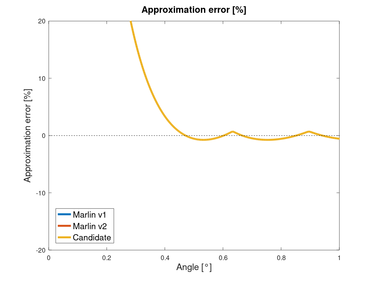
This is the MATLAB code for preparing the LUT:
%% Prepare LUT at startup

% Generate power series
entries = 16;  % Switch to 21 for precision up to 0.999999
dX = 0.5;
for i=1:entries-2
  dX(i+1) = 0.5*dX(i);
end

% Calculate acos()
dXInv = 1./dX;
X = [0, cumsum(dX)];
Y = acos(X);
Y(2:end) = Y(2:end)*1.0074696392;  % Correction factor centers the error around 0. Avoid correcting first entry to keep approximation below pi/2.
During runtime, an evaluation routine could look like this:
%% Evaluate LUT during runtime
x = cos(rand(1,1)*pi);  % Random angle in range [0, 180]° for testing purposes

% Binary search
lowInd  = 1;
highInd = entries;
currInd = round(0.5*highInd);

while true
  if x > X(currInd)
    lowInd  = currInd;
    currInd = ceil( 0.5*(currInd + highInd));
  elseif x < X(currInd)
    highInd = currInd;
    currInd = floor(0.5* (currInd + lowInd) );
  else
    lowInd  = currInd;
    highInd = currInd;
  end

  if (highInd-lowInd <= 1)
  % Alternatively use 'if (highInd-lowInd < 2)', if it's faster
    break;
  end
end

% Linear interpolation
if highInd ~= lowInd  % This if-condition is not necessary, just more elegant. It may be faster to drop it, as the 'else' is only run in the rare case where we query a value directly listed in our LUT.
  acosApprox(i) = Y(lowInd) + (Y(highInd) - Y(lowInd)) * (x - X(lowInd)) * dXInv(lowInd);
else
  acosApprox(i) = Y(lowInd);
end
The code is written deliberately strange from a MATLAB perspective with the aim of making it quicker to translate to C++. As is, I couldn't benchmark it against the existing code in the bugfix branch or acosf(). It does require five or six if/else evals, a couple of additons and substractions and six to seven multiplications. These are a problem when it comes to speed. Most of the mults are in the binary search, so they can be eliminated by accepting more if/else evaluations or some programming trickery I currently don't see.
Nonetheless I think this is a good starting point, because it's quite precise around 0° & 180° compared to our previous approaches. I think it can be sped up to a level where it's a good compromise.
XDA-Bam
on 29 Apr 2020
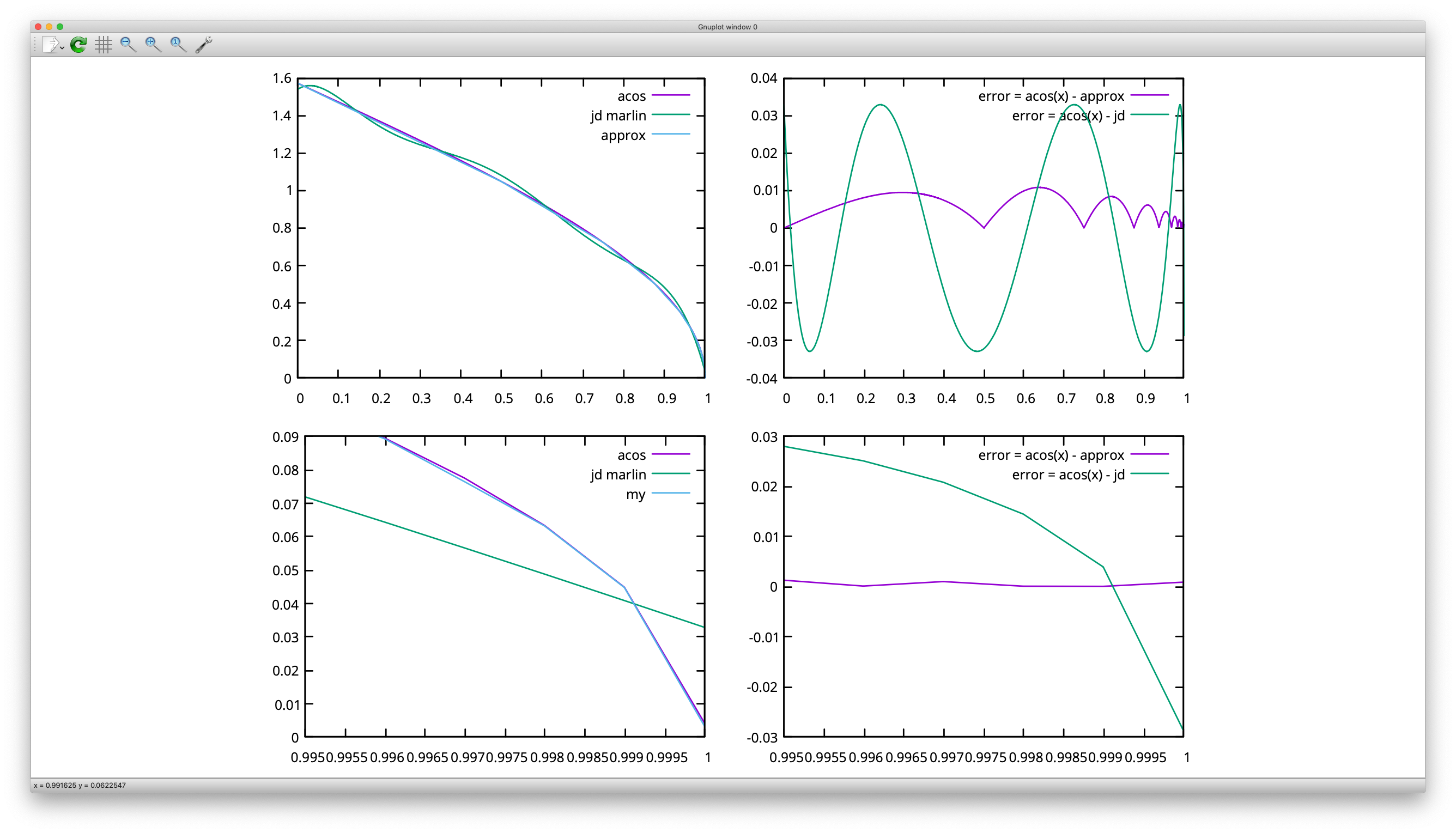
#include <iostream>
#include <math.h>

const int N = 16;
float array[N][2] = {};

float fce(float theta)
{
    // linear non uniform
    //float ret = fx0*(theta-x1)/(x0-x1)-fx1*(theta-x0)/(x0-x1);
    // quadratic non uniform
    //float ret = fx0*(theta-x1)*(theta-x2)/(x0-x1)/(x0-x2)+fx1*(theta-x0)*(theta-x2)/(x1-x0)/(x1-x2)+fx2*(theta-x0)*(theta-x1)/(x2-x0)/(x2-x1);

    int lowIdx = 0;
    int highIdx = N;
    int idx;
    float val;

    while(highIdx - lowIdx > 1)
    {
      idx = (highIdx + lowIdx) >> 1;
      val = array[idx][0];

      if(theta < val)
          highIdx = idx;
      else if (theta > val)
          lowIdx = idx;
      else
      {
          lowIdx = idx;
          highIdx = idx+1;
          break;
      }
    }

    float x0 = array[lowIdx][0];
    float x1 = array[highIdx][0];
    float fx0 = array[lowIdx][1];
    float fx1 = array[highIdx][1];
    //int dx = 2 << lowIdx; // dx is 2 x dx of next item
    float ret = fx1*(theta-x0) - fx0*(theta-x1)*2;

    std::cerr << "Theta: " << theta << " Low:" << lowIdx << " High: " << highIdx << " Idx: " << idx << " Ret: " << ret << " acos: " << acos(theta) << std::endl;

    return ret;
}

int main()
{
    std::cerr << "Fill Table" << std::endl;

    for(int i = 0; i < N-1; ++i)
    {
        float theta = (pow(2,i) - 1)/pow(2,i);
        array[i][0] = theta;
        array[i][1] = acos(theta)*pow(2,i);
        std::cerr << i << "\t" << array[i][0] << "\t" << array[i][1] << "\t" << std::endl;
    }
    array[N-1][0] = 1;
    array[N-1][1] = 0;

    std::cerr << "Canary test" << std::endl;
    float theta = 0.94;
    //theta = 0.5;
    if( abs(acos(theta) - fce(theta)) > 0.1 )
    {
        std::cerr << "Canary failed" << std::endl;
        return 1;
    }

    //return 1;

    std::cerr << "Data plot" << std::endl;
    for(float t = 0; t <= 1; t += 0.001)
    {
        float asinx =       0.032843707f
                            + t * (-1.451838349f
                            + t * ( 29.66153956f
                            + t * (-131.1123477f
                            + t * ( 262.8130562f
                            + t * (-242.7199627f + t * 84.31466202f) ))));
        std::cout << t << " " << acos(t) << " " << fce(t) << " " << acos(t) - fce(t) << " " << M_PI_2 - asinx << " " << acos(t) - M_PI_2 + asinx << std::endl;
    }
    return 0;
}
I have implemented solution with some minor tweaks and optimization. It needs only 16*2 floats LUT in memory.
daleckystepan
on 29 Apr 2020
Nice. Two small improvements: You could use a correction factor to center the error around 0, which also halves the maximum error. And what you call theta in the code is actually cos(theta), which is a bit misleading.
Can you benchmark this on a printer board?
XDA-Bam
on 30 Apr 2020
Changed to a table with 2*21 places.
Results are good - but lasts about 8.1 times longer than original acos() on a AVR 8bit 16MHz (UNO).
sketch_apr30a.txt
Times:
cos/acos: 0.90, fce/acos: 8.16, acosx/acos: 0.84
cos/acos: 0.90, fce/acos: 8.13, acosx/acos: 0.83
cos/acos: 0.89, fce/acos: 8.11, acosx/acos: 0.83
cos/acos: 0.90, fce/acos: 8.18, acosx/acos: 0.84
With N=16 it looks about the same
Times:
cos/acos: 0.90, fce/acos: 8.13, acosx/acos: 0.83
cos/acos: 0.89, fce/acos: 8.11, acosx/acos: 0.83
cos/acos: 0.90, fce/acos: 8.16, acosx/acos: 0.84
cos/acos: 0.90, fce/acos: 8.11, acosx/acos: 0.83
My version using int __builtin_clzl(unsigned long x) ( CountLeadingZerosLong() )
ACOS__-aproximation.txt
lasts currently about the same.
Speedratio lookup_acos()/acos(): 4767/567 = 8.41
Replaced
float array[N][2] = {};
with
float array0[N] = {};
float array1[N] = {};
fce/acos: 7.74
Address calculation is slow on AVRs.
AnHardt
on 30 Apr 2020
Wow, that's not encouraging 😐
I see you are using a divide during lookup:
float acos_table_lookup(float x) {
  // uint8_t i = acos_table_interval_index(x);
  int8_t i = __builtin_clzl( long((1.0f-x) * _TLL_)) - _TLL0_;
  i = constrain(i, 0, ACOS_TABLESIZE - 1);
  // like map() in float.
  return (x - acos_table_x[i]) * (acos_table_y[i+1] - acos_table_y[i]) / (acos_table_x[i+1] - acos_table_x[i]) + acos_table_y[i];
}
@daleckystepan used a solution with only multiplies and my original one also precomputed the denominator. So there's certainly some speed to gain here. But a factor of 10? What about address calculation makes this sooooo slow?
XDA-Bam
on 30 Apr 2020
I have another idea how can I optimize the code more. I will try it and we will see. I will keep you updated (hopefully in a few hours).
daleckystepan
on 30 Apr 2020
1000 evaluations on atmega 2560 16MHz
acos: 180 ms
asinx: 127 ms
approx: 103 ms (my function without any tuning)
approx: 99 ms (using two different arrays instead of one big with pointer arithmetics)
daleckystepan
on 30 Apr 2020
AVR addresses are 16 bit -> to be calculated in 8 bit registers -> far more than one cycle.
AnHardt
on 30 Apr 2020
const int N = 16;
const unsigned long _TLL_ = 1L << N;
const int _TLL0_ = __builtin_clzl( _TLL_ ) + 1;
float array0[N] = {};
float array1[N] = {};

inline float approx(float t)
{
    int lowIdx = __builtin_clzl( long((1.0f-t) * _TLL_)) - _TLL0_;

    float *a0 = array0+lowIdx;
    float *a1 = array1+lowIdx;

    return *(a1+1)*(t-*a0) - *a1*(t-*(a0+1))*2;
}
    for(int i = 0; i < N-1; ++i)
    {
        float theta = (pow(2,i) - 1)/pow(2,i);
        array0[i] = t;
        array1[i] = acos(t)*pow(2,i);
    }
    array0[N-1] = 1;
    array1[N-1] = 0;
We probably wont find faster solution :) Not beautiful but pretty fast.
We can apply correction factor also and hopefully that's it.
For 10k samples:
acos: 1820 ms
asinx: 1301 ms
approx: 1008 ms
daleckystepan
on 30 Apr 2020
With
...
    while(highIdx - lowIdx > 1)
    {
      idx = (highIdx + lowIdx) >> 1;
      val = array0[idx];
      // Precalculating sign(theta - val) is not faster. Adds two integer compares to the two float compares.
      if(theta < val) highIdx = idx; // this is at least 2 times more likely than the other case(s).
/*    Removed because this case is handled by the while loop.
 *    Speeding up the N case where it bites is in average not worth the infinit cases where we have the extra compare
 *      else if (theta == val) { // seems to evaluate a bit faster than '>'.
 *        lowIdx = idx; highIdx = idx+1; break;
 *     }
 */
     else lowIdx = idx;
    }
    return array1[highIdx]*(theta-array0[lowIdx]) - array1[lowIdx]*(theta-array0[highIdx])*2.0f;
    // Next idea is to calculate a[i]*theta + b[i]; what needs a further array.
}
i'm now at fce/acos: 7.60
AnHardt
on 30 Apr 2020
Wow! The pointer version with __builtin_clzl() is already pretty impressive.
If the array is smaller then 16 elements there is also __builtin_clz() for 16 bit integers.
With this lookup we don't need the old array0[].
So we don't need a third array when we calculate return a[i]*theta + b[i];
AnHardt
on 30 Apr 2020
10k samples
acos: 1819 ms
asinx: 1301 ms
approx: 653 ms
const int N = 15;
const unsigned int _TLL_ = 1 << N;
const int _TLL0_ = __builtin_clz( _TLL_ ) + 1;

float lutK[N] = {};
float lutB[N] = {};

inline float approx(float t)
{
    int idx = __builtin_clz( int((1.0f-t) * _TLL_)) - _TLL0_;

    return lutK[idx]*t + lutB[idx];
}
    for(int i = 0; i < N-1; ++i)
    {
        float t = (pow(2,i) - 1)/pow(2,i);

        float c = (i==0)?1.0:1.0074696392;
        float x0 = t;
        float y0 = acos(x0)*c;

        float x1 = 0.5*x0 + 0.5;
        float y1 = acos(x1)*c;

        float dx = x0-x1;

        lutK[i] = (y0-y1)/dx;
        lutB[i] = (y1*x0 - y0*x1)/dx;
    }
    lutK[N-1] = 0;
    lutB[N-1] = 0;
The race is on 😅 If I'm not mistaken, that's faster than the existing and the old approach _and_ it's more precise. Only disadvantage of using 15 elements is, that we're already diverging around 0.6° instead of 0.45°. But the error is an acceptable 7.5% at 0.5°. So, a marginal loss for a 35% faster function.
PR?
XDA-Bam
on 30 Apr 2020
Yes, error is still acceptable and we can improve it easily with adding more elements (and update to __builtin_clzl ). I have created the PR but I'm not sure about the code at all :D
daleckystepan
on 1 May 2020
Please test the current bugfix to see if we can close this issue.
thinkyhead
on 3 May 2020
Does the proposed fix still have side effects like increasing cpu time requirement? That could be breaking on low-end boards if so.
richfelker
on 3 May 2020
Proposed fixed is approximately 2x faster and about 3x more accurate.
daleckystepan
on 3 May 2020
Is https://github.com/MarlinFirmware/Marlin/issues/15473 believed to be fixed too? I've been avoiding JD because of uncertainty about that as well.
richfelker
on 3 May 2020
I am currently on version 2.0.5.2, and I am legit unable to cause these issues to appear. I tried using the same tux model like the one used back in issue #17146, and I was unable to get any difference to show up with JD enabled and disabled.
On the picture, JD enabled (left), classic Jerk (right). I am using SKR1.4 Turbo with TMC2209 drivers.
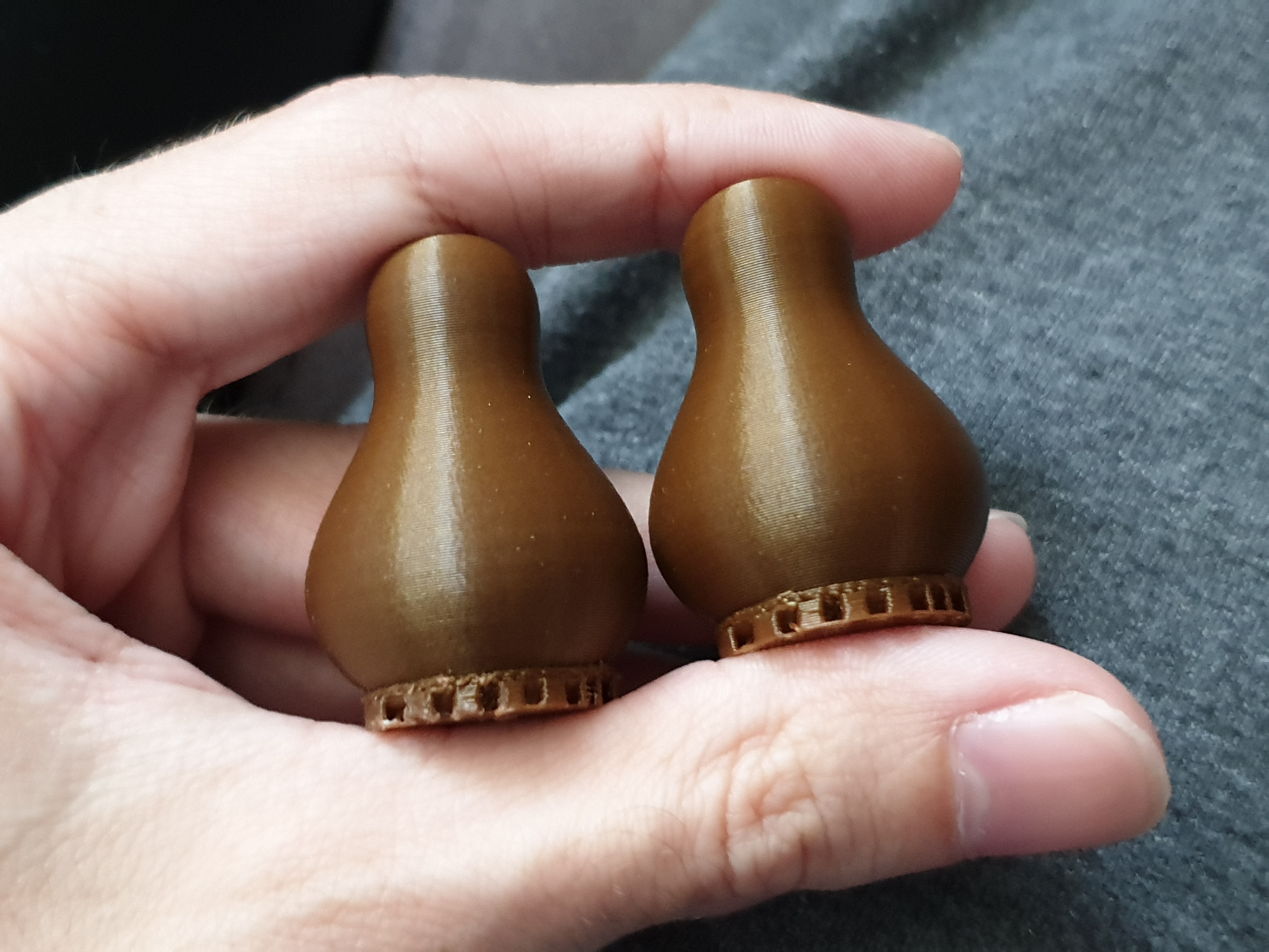
Am I missing something...?
 Thorinair
on 15 May 2020
Thorinair
on 15 May 2020
@Thorinair Could you test our JD_single_arc_test.zip?
qwewer0
on 15 May 2020
Absolutely, will do and report the results.
EDIT: Scratch that, can't test it because its in gcode format. Why not STL?
EDIT2: I see, its just a "dry" print, that should be okay... I will try and see
Thorinair
on 15 May 2020
@Thorinair This is essentially a problem of the discretization, which means it (also) depends on your slicer. If you download the pinguin and slice it yourself, the slicer and the settings will likely be different from those of other users, who see the problem. If you run the JD_single_arc_test GCode, the slicer is out of the equation and it's easier to compare results.
Also, please let us know which slicer and settings you used to slice your Tux!
XDA-Bam
on 15 May 2020
This is why I hate running unknown gcodes. Made the Z axis go too fast, stalling the motors. Now I need to readjust the offset between left and right motors again.
But, to answer the question, the motors moved perfectly smoothly without any hint of stutter.
Thorinair
on 15 May 2020
Also, please let us know which slicer and settings you used to slice your Tux!
I used Cura, however, I do use 0.4 max resolution, otherwise Octoprint is the one in my chain that won't be able to keep up.
Thorinair
on 15 May 2020
This is why I hate running unknown gcodes. Made the Z axis go too fast, stalling the motors. Now I need to readjust the offset between left and right motors again.
You can check the gcode yourself. It is not a full sliced gcode from an stl, but only a snippet from the original one, repeated 15 times.
And it has only one Z movement command which is most likely limited by your DEFAULT_MAX_FEEDRATE setting in the firmware.
You can change the gcode accordingly:
From:
G1 F3000 ; Set the motion velocity
G1 Z10.0 ; Raise Z Axis 10mm
To:
G1 Z10.0 F180; Raise Z Axis 10mm
G1 F3000 ; Set the motion velocity
But, to answer the question, the motors moved perfectly smoothly without any hint of stutter.
Did you put your hands on the X and Y axis motor or bed/print head to feel the stutter?
qwewer0
on 15 May 2020
Did you put your hands on the X and Y axis motor or bed/print head to feel the stutter?
I cannot say that I have, but the stutters, when they happen, are usually quite loud on my printer. Ive experienced them before on 8-bit boards when it was starved for commands from Octoprint. Regardless. I will try it again once my next tux test is done (removing the max resolution limits).
Thorinair
on 15 May 2020
Tried it, I am honestly not sure if I feel anything out of the ordinary both with JD enabled and disabled...
Thorinair
on 15 May 2020
@Thorinair Thanks for testing. Did you print the Tux again without the res limits, as you wrote before? If so, is there any visible difference?
XDA-Bam
on 16 May 2020
@Thorinair Thanks for testing. Did you print the Tux again without the res limits, as you wrote before? If so, is there any visible difference?
I did, and the tux actually came out even better, as it didnt’s have imprecisions introduced by Cura any more. Printed indeed again with JD turned on.
Thorinair
on 16 May 2020
One thing I have noticed is that people having the problem have s-curve acceleration enabled, while I do not. I tried to use it a while back on a simple calibration cube, and it produced massive amounts of vibrations (way more than normal accel), and even resulted in gaps on the top part of the print, so I gave up on it as I saw no added benefit. May it be an interraction between s-curve and JD specifically that causes this?
Thorinair
on 16 May 2020
S-Curve has been discussed and tested. It does not make a difference for those who tried it (including me). If you've got LA + S-Curve enabled, though, it might also give you problems - with a different cause. So, sadly, it's not easy to diagnose all this.
XDA-Bam
on 16 May 2020
Wait, so what is the recommend for something like an Ender 3 with an aftermarket 32bit board (no FPU)?
Because it seems like combining any of these features seems to be a problem, should you even combine them?
I mean: S Curve Acceleration, Junction Deviation, Linear Advance
Because I experience some slight wobble in curves when just using SCA & LA which gets magnified when using JD instead of Classic Jerk.
Is turning on S Curve Acceleration even recommended for a bowden setup? I'm a bit confused here since all of the features somehow negativly influence each other :(
 Seref
on 16 May 2020
Seref
on 16 May 2020
Wait, so what is the recommend for something like an Ender 3 with an aftermarket 32bit board (no FPU)?
This is kind of an off-topic question, but to make it short:
- Don't combine LA with S-Curve, it might work but can also fail, depending on the print.
- JD currently seems to be bugged in all branches, with different problems in each branch. It's safer to use Jerk for now.
XDA-Bam
on 17 May 2020
JD currently seems to be bugged in all branches
It didn't seem too bad in most Marlin 1.1.x and 2.0.x releases. It would be interesting to see how the earliest versions test out in comparison.
thinkyhead
on 19 May 2020
JD currently seems to be bugged in all branches
It didn't seem too bad in most Marlin 1.1.x and 2.0.x releases. It would be interesting to see how the earliest versions test out in comparison.
I am still running 1.1.9 for productive tasks on my Ender 3. It's got the same problems with zits/surface imperfections due to stutter on curves when using JD. That's how I originally found this thread and became involved (see posts waaaay up this thread).
XDA-Bam
on 20 May 2020
It's got the same problems with zits/surface imperfections due to stutter on curves when using JD
Do you still see that if you follow the recent "YouTuber advice" to set the slicer to use minimum-length segments? This is supposed to eliminate the planner starvation that causes pauses to occur when printing many small segments in a row.
There was also a possible problem related to screen throttling in some earlier versions. If you print with the screen fully disabled do you see any improvement in the surface quality?
thinkyhead
on 20 May 2020
It's got the same problems with zits/surface imperfections due to stutter on curves when using JD
Do you still see that if you follow the recent "YouTuber advice" to set the slicer to use minimum-length segments? This is supposed to eliminate the planner starvation that causes pauses to occur when printing many small segments in a row.
Did not check, yet. The JD_single_arc_test.gcode stutters on three segments, which are only ~0.1 mm long. It disappeared when I increased #define MIN_STEPS_PER_SEGMENT to 16, which eliminated all segments smaller than ~0.2 mm from the print by joining them to the next. Increasing buffer size had no effect, though.
EDIT: Switching to //#define SLOWDOWN also had no effect on the stutter. This would indicate, that planner starvation is not happening here, right?
There was also a possible problem related to screen throttling in some earlier versions. If you print with the screen fully disabled do you see any improvement in the surface quality?
Currently do not have the setup to print without a screen, sorry.
XDA-Bam
on 20 May 2020
I did some tests last night before hopping on Discord, but it doesn't seem to be a computational bottleneck with the LCD. I changed the refresh interval from 100 to 250, and the print began to halt at the same location. I also changed the update rate to 50ms with no loss in performance. This was with 2.0.x with the above changes to the planner.
As noted, the stutters occur beginning at the exact same location of the gcode file on my machine, regardless of settings. The issue occurs at the same spot regardless of speed.
I can post the gcode file, but be aware it's based on a 0.8 nozzle. The issue entirely vanishes with classic jerk.
XBrav
on 21 May 2020
As suggested by @swilkens in #18031, I just checked the most recent bugfix (929b3f6) and took out all code related to limit_sqr from planner.cpp (that's lines 2308 to 2389). As expected, this eliminated all stutter from the arc in JD_single_arc_test.gcode. The short "pause" on the very last move before homing remained, though.
XDA-Bam
on 25 May 2020
I've been using classic jerk because of problems with JD, but today I hit a similar problem, and associated layer shift issues, with clasic jerk, described in a comment here: https://github.com/MarlinFirmware/Marlin/issues/12403#issuecomment-633659126
Is there any similar segment length limit with classic jerk that could be the cause here?
richfelker
on 25 May 2020
Here's a fun test for you folks to try. I'm using it to find the bottlenecks on my system currently:
This test runs several movements using y=sin(x/360×2×3.14159)*90, with the final movement cycle moving Z at Z=Y
There are 5 tests in total:
1) 90 point progression from X:0 Y:0 to X:90 Y:90 in increments of 1mm on X.
2) 900 point progression from X:0 Y:0 to X:90 Y:90 in increments of 0.1mm on X.
3) 9000 point progression from X:0 Y:0 to X:90 Y:90 in increments of 0.01mm on X, rounded to 0.0001 precision.
4) 9000 point progression from X:0 Y:0 to X:90 Y:90 in increments of 0.01mm on X, with full precision.
5) 9000 point progression from X:0 Y:0 Z:0 to X:90 Y:90 Z:90 in increments of 0.01mm on X, with full precision.
Based on running these tests on Classic Jerk, I found the most stutters on the final test, even with high vmax on Z. After playing for a bit, I found there's some kind of bottleneck in the Z stepping, where it is 400 / mm on my machine. After reducing the microstepping to 4, and dropping the steps / mm to 100, there was a noticeable speed increase on test 5.
Bearing in mind this does not directly address the computational bottlenecks seen in this ticket, it may provide a bit better diagnostics in finding the source of the bottleneck. With this test, you can run it with or without bed levelling. Just be sure you have 90mm of travel available from your start, and run a G28 first (I didn't include a homing call).
For the record, my experience was on a BTT E3 DIP STM32F103RET6, with 2209s in UART for X, Y and E0, and a 5160 SPI for Z.
XBrav
on 25 May 2020
Problem in https://github.com/MarlinFirmware/Marlin/issues/17342#issuecomment-633670626 above seems to have been triggered by very short segments. The model was produced in OpenSCAD with $fn=200 and was sliced with Cura with my usual high-precision resolution/deviation settings. Reslicing with Cura's defaults produces smooth circular motion and hasn't hit any layer shifts so far.
richfelker
on 27 May 2020
Cross-post: I just got the right cable and did some serial debugging running 2.0.x-bugfix. Compared LUT results for junction_theta to Minimax poly (#define JD_USE_LOOKUP_TABLE vs. //#define JD_USE_LOOKUP_TABLE). Results in this post.
EDIT: Update from today in this post. Found a divide by zero induced by the LUT for junction angles close to 180°.
XDA-Bam
on 29 May 2020
I would like all of you to join in and brainstorm ideas for a solution. Our main problem is - to the best of my knowledge - explained in this post. Ideas welcome.
XDA-Bam
on 10 Jun 2020
>>> For everybody who is affected by this issue <<<
When using the newest bugfix-2.0.x, you can now change the config parameter
#define JD_HANDLE_SMALL_SEGMENTS
in Configuration.h to
//#define JD_HANDLE_SMALL_SEGMENTS
and thereby deactivate the code which is causing most (all?) of the stuttering and surface blobs. This is a workaround until an actual fix may be implemented, which - I guess - is at least a couple of months away.
XDA-Bam
on 17 Jun 2020
Can you clarify what side effects we might see from enabling this workaround? Surely there are some cons (which the PR didn't seem to mention) or this would qualify as a fix not a workaround.
richfelker
on 17 Jun 2020
This restores the original Junction Deviation behaviour, as implemented in GRBL. That means segment length has no influence on junction speed. Thereby, junction speeds along curved paths are higher, the more finely sliced the path (more segments for same curve ➡️ smaller angles per junction ➡️ higher speeds).
From the examples I looked at, it prints a lot of curves faster overall. You can counteract this sideffect by increasing the smallest segments your slicer uses to a sensible value (say, 0.5 mm).
XDA-Bam
on 17 Jun 2020
@XDA-Bam I've been disabling the call NOMORE(vmax_junction_sqr, limit_sqr); in planner.cpp on every single update.
Does JD_HANDLE_SMALL_SEGMENTS disable the above call?
 Lord-Quake
on 17 Jun 2020
Lord-Quake
on 17 Jun 2020
@Lord-Quake Yes. Plus the code required to calculate limit_sqr, because it's not used elsewhere.
XDA-Bam
on 17 Jun 2020
I can confirm by setting
//#define JD_HANDLE_SMALL_SEGMENTS
the print comes out as expected without issues.
Lord-Quake
on 18 Jun 2020
@XDA-Bam: If I'm reading your reply correctly, that means that use of sufficiently small segments allows bypass of JD's jerk limits to exceed the physical acceleration capabilities of the machine by an unbounded margin. Is this correct? In which case, disabling JD_HANDLE_SMALL_SEGMENTS would only be safe assuming suitable limits on segment size enforced in the slicer.
richfelker
on 21 Jun 2020
@richfelker No, this is not the case. At least in theory. The acceleration limits for all three axes are still respected for every junction. If there's more junctions in a given curve, each junction will have a smaller angle. That means the effective acceleration per axis and junction is also smaller, while the allowable acceleration stays the same. This results in higher junction speeds and is physically correct.
However, basic JD by design does not take into account inertia and dampening effects and assumes that the print head enters each junction "undisturbed", which is absolutely not the case if each segment is only 0.1 mm in length. Thereby, in practice, there will be too many disturbances left from the last change of direction when entering the next junction within a fraction of a millimeter. The exact length after which you could consider a move undisturbed varies per printer and print settings. In the end, you will have to set a sensible slicer setting for the smallest segment length and re-tune your JD accordingly (-> lower).
XDA-Bam
on 21 Jun 2020
Just as an update, with the new JD_HANDLE_SMALL_SEGMENTS, my CR10s5 with a SKR 1.4 Turbo is producing some excellent results. There doesn't appear to be any planner stuttering when printing a Mandalorian helmet, and ghosting seems non-existent.
XBrav
on 6 Jul 2020
@XDA-Bam: I wasn't thinking of increasingly fine slicings of the same curve, but a model where the entire GCODE is produced by an "attacker" trying to get the machine to misbehave. Even under that model, is it impossible to produce unbounded acceleration with small segments and JD not handling them?
richfelker
on 7 Jul 2020
@richfelker That is covered by my last answer: In theory, all acceleration limits are respected. In practice, inertia, vibrations and dampening effects are not covered and can't be predicted. I can't exclude that such an attack would push your printer above its limits - especially if you configured your maximum acceleration or maximum feedrates to physically borderline safe values.
In any case, it is a super exotic scenario and printing unknown GCodes is always a security risk and not recommended for this exact reason. Plus, there's lots of additional, more reliable attack vectors to damage a machine (see i.e. here). If you don't feel comfortable setting #define JD_HANDLE_SMALL_SEGMENTS, simply don't do it.
XDA-Bam
on 7 Jul 2020
Indeed I'm not actually using untrusted gcodes; that's just the best model to reason in terms of. I'm more thinking STL files with ridiculous fine details, which are fairly common on model sharing sites full of stuff produced by 3D graphics folks who don't understand design for printability.
For context about why I'm asking, for now I'm still using classic jerk, because I hit to many problems with JD, but I'm trying to keep track of improvements and gauge when/whether I might want to try it again. Getting layer shifts during long prints was really frustrating and that's why I'm so cautious about anything that might reintroduce motion exceeding the intended accel/jerk limits.
richfelker
on 7 Jul 2020
OK, that's certainly a more likely scenario. Well, in short: I use Classic Jerk again and I don't see myself switching back to JD until a new algorithm is implemented, which can look ahead when calculating junction speeds. If you're conservative and just want reliable prints, I'd recommend CJ 😉
XDA-Bam
on 7 Jul 2020
in planner.cpp line 2335 Junction deviation junction_cos_theta variable seems to be calculated with extruder speed.
1- why?
2- when you add a 4th element to a 3D vector then dot product is not equal to any 3D trigonometry function we know, and thus I think this is why enabling Junction Deviation and Linear Advance will result in unknown behavior of the extruder path. even if you are gonna use the extruder speed corrections from the linear advance in junction deviation function I think you need to add that speed to the entrance and exit velocity and then do the calculations for a 3D vector.
please tell me why I'm wrong.
regards
 ShadowOfTheDamn
on 9 Jul 2020
ShadowOfTheDamn
on 9 Jul 2020
please tell me why I'm wrong.
I can't tell you why you are wrong - but you are.
Just because humans can't imagine angles in a 4-dimensional room does not mean they don't exist.
Maybe it will help you do make a simple excel-sheet. Put in 2 vectors with 4 dimensions. Calculate their length and their common dot product. Finally calculate the angle from that.
Begin with one dimension. For example put a positive number into the x component of the first vector and an other positive value into the x-component of the second vector. The result will be 0°.
Now make the positive number in one of the vectors negative. The result will be 180°.
There are not more possible results in only one dimension. Either its the same direction or the other.
Now try the same with the y, z and e components. If the other components are zero you'll get exactly the same results.
Next try in two dimensions (x,y) and get a feeling for how the angle changes when you change the values.
After that try two dimensions but (x,z), (x,e), (y,z) and so on. That all behaves well and you should be able to imagine the angle.
After that try to fill 3 dimensions - so always let one component at zeros. Regardless what component you leave at zero you should be able to visualize the remaining 3 as a normal 3 dimensional system by just ignoring the fourth dimension.
What do you have to set in to get 0°, 180° or 90°. (try simple numbers like 0 and +-1)
Finally add the fourth dimension components. Again try to produce 0°, 90°, 180° angles.
Does that follow the same rules as in 3-dimensions?
Does that look trustworthy to you? To me it does.
AnHardt
on 9 Jul 2020
1- why?
Because it's for the e-axis as (im)possible to make sudden changes in speed as for the others. (No - we don't violate physics with infinit accelerations)
'junction deviation' is really just one, mathematically relatively cheap, way to calculate a speed for that corner - the path will not follow the imagined circle segment.
AnHardt
on 9 Jul 2020
Thanks for the reply but you are wrong.
now let me tell you some physics,
the extruding inertia does not relate to the head movement in any logical manner. extruder inertia or lag is being controlled by linear advance and S Curve acceleration so dont tell me we get infinite acceleration.
the use of junction deviation on extruder should be separated from XYZ movement of the head. that is clear as glass. the kind of inertia in the head is from the moving mass of the head while the extruder inertia is mainly due to plastic extrusion force and related to non-Newtonian liquid viscosity of the molten plastic.
ShadowOfTheDamn
on 9 Jul 2020
junction deviation for extruder should be calculated for a 1D vector, which I believe Linear advance will do it correctly.
while it is calculated for a 3D movement vector for XYZ movement. The relation between extruder minimum speed and the maximum movement speed change is due to the layer height and nozzle diameter and when extruder maximum speed change is lower this will relate the system to the movement and vise versa.
ShadowOfTheDamn
on 9 Jul 2020
In a machine like a Pusa-i3 there are NO dependent axes. The common inertia or 'Centrifugal forces' in a circle are completely not relevant/existent. In a CORE- or DELTA- systems thing are much more complicated. In all cases the masses to move are different for the different axes.
For that i told you its just one model for calculating some speeds at corners. Its calculating lower speeds for sharper corners and higher for less sharp corners in a multidimensional room. That's about right. At least it seemed, when suggested, to be better than the fixed 'jerk-speeds' of 'classic jerk'.
The calculation for 'sharpness' of the angle on a more than 3-dimensional room seems to be correct - that was my main point.
The "expectation" 'junction deviation' could be a "correct" model of the involved physics is wrong - that was never intended. For that - it is much to simple.
'Linear advance' and 'S-Curve-Acceleration' are not about speeds at the junctions.
If you had followed my link you'd have seen why the seemingly infinite acceleration of 'classic jerk' is possible. (Because at that moment only the magnetic field is kind of jumping - that accelerates the masses)
AnHardt
on 9 Jul 2020
actually the definition of the junction deviation itself defines infinite acceleration, just like jerk (please rename the variable as it is wrongly understood, something like maximum instantaneous speed change would be good)), junction deviation just uses the corner angle to defines the junction speed instead of using fix speed in the jerk definition. So we are actuating the printer frame with a step pulse, using different jerk or junction deviation will result in different kinetic energy and regarding to the moving system damping will result in ripples at the corners. this can be easily verified by measuring the distance of the ripples and its bump height for different accelerations and print speeds. you will find the same vibration frequency. So the infinite acceleration (infinite force is needed on that moment which will result in a step actuation and vibration of the motion system) . as you said junction deviation is a very simple method. sophisticated methods are needed for the system in each axis or even multi axis movements for perfect movements which compensates the vibrations online.
by decreasing junction deviation or jerk you are decreasing the actuation speed and energy which will result in the same frequency and ripple distance on the object surface but with lower bump height.
so to remove that artifact you have three choices (at least these three are just in my mind):
1- make a very very very rigid printer skeleton (by skeleton I mean even the moving parts should have a good rigidity) so the first natural frequency which always absorbs most of the energy be so high regarding the printer speed that the vibrations damp so fast that the surface does not get affected in a large length of head movement.
2- lower the printing speed and acceleration which again will result in lower distance of the vibration along the head movement path
3- make a sophisticated control which foresee and compensate for the head movement path regarding the direction and frequency of the system (almost impossible for at least a century cause of computational power need for that kind of calculations)
so to sum up junction deviation only helps the printer/planner to select a more suitable jerk speed with regards to the junction angle and curvature.
s curve acceleration will only help continues and Differentiable jerk (acceleration derivative) and acceleration and speed and position of the linear movement.
linear advance will compensate for the lead and lag of the extruder pressure. (make the extruder pressure continues and maybe differentiable)
each of these controllers should be separate and independent of each other or they make instability in their controlling algorithm.
anyone wants to remove ghosting or similar artifact don't use these options. these options may reduce ghosting but will not remove it.
for the prusa or i3 style printers you have mentioned, as you have said before junction deviation is a very simple and cheap algorithm and if you want to control the i3 Style printer you should control all axis separately.
now some genius says it is easy for 1 axis movements but what will you do for multi axis movements i.e. moving in x=y line.
the answer is very simple, even simpler than junction deviation algorithm.
the resulting velocity here x=y is something like (V_x , V_y) vector in which V_x=V_y
we use the projected speed on each axis because the maximum acceleration tolerable with each axis is different regarding to its mass. (you can understand me by imagining the a 2d movement like a circle) now if you omit the X axis you see that Y axis is only going back and forth with the projected speed of V on the Y axis which is V_y thus you can control its vibration by controlling V_y
just for the sake of brevity the same is applied for the X axis.
for Core-XY the vibrations on the Y axis will result in a shift in X axis (belt tensions) which then can be added to the projected x axis speed
but for the delta the math is more complicated.
so each machine needs different acceleration and JD/Jerk control and they are not universal.
when the maximum change of speed in any axis reaches the critical value all of the speeds of the system are scaled down securely to the correct speed by that single ratio.
That's how I see a simpler and better movement mechanism.
ShadowOfTheDamn
on 9 Jul 2020
If you are interested in 'ringing' there are some very different strategys discussed in "[FR] (Practical algorithm provided) Vibration compensation" #16531.
1- make a very very very rigid printer skeleton
That alone will not help very much. It would also need very very very high currents in the stepper coils to produce very very very high moments. Else the steppers rotor will oscillate in the field with the lowest frequency.
For a faster decrease of the amplitude some more resistance would be helpful - a kind of break - and than more power.
AnHardt
on 10 Jul 2020
1- why?
2- when you add a 4th element to a 3D vector then dot product is not equal to any 3D trigonometry function we know, and thus I think this is why enabling Junction Deviation and Linear Advance will result in unknown behavior of the extruder path. even if you are gonna use the extruder speed corrections from the linear advance in junction deviation function I think you need to add that speed to the entrance and exit velocity and then do the calculations for a 3D vector.
I think @ShadowOfTheDamn may be right, anyone willing to give this a shot?
thierryzoller
on 10 Jul 2020
I have tried and removed the extruder speed from the calculations of junction deviation angle you need to change the planner cpp:
  float junction_cos_theta = (-prev_unit_vec.x * unit_vec.x) + (-prev_unit_vec.y * unit_vec.y)
                           + (-prev_unit_vec.z * unit_vec.z) + (-prev_unit_vec.e * unit_vec.e);
TO
  float junction_cos_theta = (-prev_unit_vec.x * unit_vec.x) + (-prev_unit_vec.y * unit_vec.y)
                           + (-prev_unit_vec.z * unit_vec.z);
and planner.h:
  FORCE_INLINE static void normalize_junction_vector(xyze_float_t &vector) {
    float magnitude_sq = 0;
    LOOP_XYZE(idx) if (vector[idx]) magnitude_sq += sq(vector[idx]);
    vector *= RSQRT(magnitude_sq);
  }

  FORCE_INLINE static float limit_value_by_axis_maximum(const float &max_value, xyze_float_t &unit_vec) {
    float limit_value = max_value;
    LOOP_XYZE(idx) {
      if (unit_vec[idx]) {
        if (limit_value * ABS(unit_vec[idx]) > settings.max_acceleration_mm_per_s2[idx])
          limit_value = ABS(settings.max_acceleration_mm_per_s2[idx] / unit_vec[idx]);
      }
    }
    return limit_value;
  }
TO
  FORCE_INLINE static void normalize_junction_vector(xyze_float_t &vector) {
    float magnitude_sq = 0;
    LOOP_XYZ(idx) if (vector[idx]) magnitude_sq += sq(vector[idx]);
    vector *= RSQRT(magnitude_sq);
  }

  FORCE_INLINE static float limit_value_by_axis_maximum(const float &max_value, xyze_float_t &unit_vec) {
    float limit_value = max_value;
    LOOP_XYZ(idx) {
      if (unit_vec[idx]) {
        if (limit_value * ABS(unit_vec[idx]) > settings.max_acceleration_mm_per_s2[idx])
          limit_value = ABS(settings.max_acceleration_mm_per_s2[idx] / unit_vec[idx]);
      }
    }
    return limit_value;
  }
and also used steps_dist_mm.a and steps_dist_mm.b instead of steps_dist_mm.x and steps_dist_mm.y in planner.cpp line 2315 when declaring unit_vec variable for my core-XY setup. lol the results are now better with no weird acceleration and deceleration happening and also it lowered the ringing in the sharp corners.
Just need to add some control for the extruder maximum junction deviation. (but I know it is useless)
thats why: marlin default extruder acceleration is 10000 and the maximum extruder speed change is 5mm/s in jerk setting.
5 mm/s for a 0.4mm nozzle with 0.2 layer height means a 150mm/s nozzle speed change which is clearly not happening while printing.
I am using M204 P1250 R1250 T1250
and M205 J0.03 for my setup.
ShadowOfTheDamn
on 10 Jul 2020
Pictures with before and after or it didn't happen 😉
Lord-Quake
on 10 Jul 2020
lol here you are:
Pictures with before and after or it didn't happen 😉
left after, right before.

please be polite and don't doubt others.
So now it happened. Now it is time for you guys to say that I'm wrong.
ShadowOfTheDamn
on 10 Jul 2020
OK, now we have something to go with :-)
I would like you to post your exact settings, layer height, infill type, percentage, outer wall print speed... the works.....
LA ON/OFF at what settings? What JD value did you use and just for reference what printer.
Also post the stl link of the test object.
I'm curious by nature :-)
Lord-Quake
on 10 Jul 2020
OK,
S3D
layer height 0.2
infill 20%, rectilinear,
outer wall 37.5mm/s, shells 75mm/s, infill 60mm/s
LA on, K=0.14
JD = 0.0309
Printer is home made.
stl link: https://www.thingiverse.com/thing:277394
ShadowOfTheDamn
on 10 Jul 2020
@ShadowOfTheDamn can you maybe provide a patch so that - less savvy individuals like me - can also post their results? I am also on CORExy and my results look like yours on the right.
thierryzoller
on 10 Jul 2020
use the latest bugfix with the following files instead of what is in
..\Marlin\Marlin\src\module :
I am using M204 P1250 R1250 T1250
and M205 J0.0309 for my setup.
Simplify 3D
layer height 0.2
infill 20%, rectilinear,
outer wall 37.5mm/s, shells 75mm/s, infill 60mm/s
LA on, K=0.14
JD = 0.0309
Printer is home made.
stl link: https://www.thingiverse.com/thing:277394
ShadowOfTheDamn
on 10 Jul 2020
As I mentioned I'm curious so I whooped up my Ender 3 and sliced the settings you provided. Unfortunately you missed ".... the works..." so the missing settings are assumptions on my part. E.g. nozzle 0.4mm, 2 perimeters, bottom/top infill 4 layers, ....
And I upped the aunty by using 40mm/s outer wall print speed.
Close up pictures always show more details than the naked eye so here my result without doing any tinkering like seam placement and the like (same cube pictured).
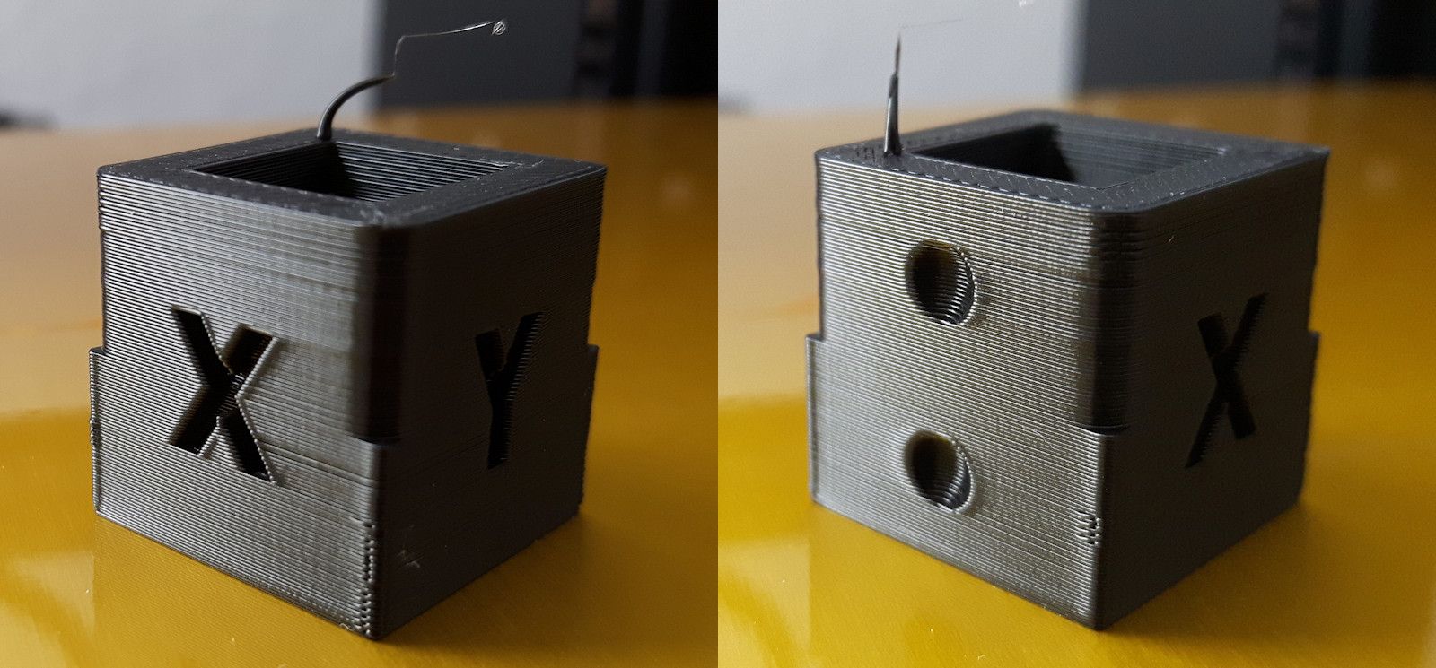
Printed with Marlin STRING_DISTRIBUTION_DATE "2020-06-29"
Printed as reference for future comparisons and for discussions.
I will refrain from any comments as per politeness requirements :-)
Lord-Quake
on 10 Jul 2020
@Lord-Quake : I am not sure which one is before and after, why show a different side? Are you trying to show you have no ripples or a before and after the patch. If the former, I am not sure what that contributes :)
thierryzoller
on 10 Jul 2020
Yea, I should have added it's the same cube. (I edited my post)
Personally I don't see a problem in the present code if compared to the example posted by ShadowOfTheDamn. But that is as far as I going to go for reasons of politeness :-)
However I have a reference if in fact the conclusion is that the present code is not optimal.
Lord-Quake
on 10 Jul 2020
As I mentioned I'm curious so I whooped up my Ender 3 and sliced the settings you provided. Unfortunately you missed ".... the works..." so the missing settings are assumptions on my part. E.g. nozzle 0.4mm, 2 perimeters, bottom/top infill 4 layers, ....
And I upped the aunty by using 40mm/s outer wall print speed.Close up pictures always show more details than the naked eye so here my result without doing any tinkering like seam placement and the like (same cube pictured).
Printed with Marlin STRING_DISTRIBUTION_DATE "2020-06-29"
Printed as reference for future comparisons and for discussions.
Thanks for the reply
The settings are right .4 mm nozzle and 2 walls 4 bot and top layers.
First of all I'm talking about my core xy configuration. So ender 3 ?
Second my part does not show any ringing on Y axis ( it has a very very faint sign of ringing)
Third please as you have asked me tell us your config e.g. acceleration junction deviation and ....
Fourth what slicer you are using , don't let slicer reduce print speed regarding the layer time. I used minimum layer time 5 sec.
I am here to help myself increase my print quality and in its way maybe, only maybe help others too.
ShadowOfTheDamn
on 10 Jul 2020
Yea, I should have added it's the same cube. (I edited my post)
Personally I don't see a problem in the present code if compared to the example posted by ShadowOfTheDamn. But that is as far as I going to go for reasons of politeness :-)
However I have a reference if in fact the conclusion is that the present code is not optimal.
So what you showed is that you have no obvious issue, ok, for those that have, his patch may work prooving his point about architecture aligned JD
thierryzoller
on 10 Jul 2020
It is an interesting subject and I have my reference setup for eventual code changes.
Lord-Quake
on 10 Jul 2020
Sorry, for going back a little in time, but this discussion advanced very quickly. I have some comments on aspects @ShadowOfTheDamn mentioned:
so to remove that artifact you have three choices (at least these three are just in my mind):
1- make a very very very rigid printer skeleton (by skeleton I mean even the moving parts should have a good rigidity) so the first natural frequency which always absorbs most of the energy be so high regarding the printer speed that the vibrations damp so fast that the surface does not get affected in a large length of head movement.
2- lower the printing speed and acceleration which again will result in lower distance of the vibration along the head movement path
3- make a sophisticated control which foresee and compensate for the head movement path regarding the direction and frequency of the system (almost impossible for at least a century cause of computational power need for that kind of calculations)
Very rigid, or very well dampened - so maybe four options.
so to sum up junction deviation only helps the printer/planner to select a more suitable jerk speed with regards to the junction angle and curvature.
s curve acceleration will only help continues and Differentiable jerk (acceleration derivative) and acceleration and speed and position of the linear movement.
linear advance will compensate for the lead and lag of the extruder pressure. (make the extruder pressure continues and maybe differentiable)
each of these controllers should be separate and independent of each other or they make instability in their controlling algorithm.
These algorithms cannot all be independent, because some act on the same parts and motors. You can make them run independent in software, but the results on the hardware will be partially superimposed. It's probably best to already foresee this interaction in the control software.
anyone wants to remove ghosting or similar artifact don't use these options. these options may reduce ghosting but will not remove it.
Well... there is no magic wand to remove these artifacts, and the correct config & print settings can make them essentially invisible. So I wouldn't be so harsh to not recommend using them.
for the prusa or i3 style printers you have mentioned, as you have said before junction deviation is a very simple and cheap algorithm and if you want to control the i3 Style printer you should control all axis separately.
now some genius says it is easy for 1 axis movements but what will you do for multi axis movements i.e. moving in x=y line.
the answer is very simple, even simpler than junction deviation algorithm.
the resulting velocity here x=y is something like (V_x , V_y) vector in which V_x=V_y
we use the projected speed on each axis because the maximum acceleration tolerable with each axis is different regarding to its mass. (you can understand me by imagining the a 2d movement like a circle) now if you omit the X axis you see that Y axis is only going back and forth with the projected speed of V on the Y axis which is V_y thus you can control its vibration by controlling V_y
just for the sake of brevity the same is applied for the X axis.
for Core-XY the vibrations on the Y axis will result in a shift in X axis (belt tensions) which then can be added to the projected x axis speed
but for the delta the math is more complicated.so each machine needs different acceleration and JD/Jerk control and they are not universal.
when the maximum change of speed in any axis reaches the critical value all of the speeds of the system are scaled down securely to the correct speed by that single ratio.
...
I agree somewhat. I've said before that we essentially need to look at the limits of the basic moving parts of each printer:
- Group 1: One acceleration and one "real" jerk (da/dt) limit per movement axis (let's call them A, B, C)
(on a Delta, you might need six instead of three limits per axis, to cover horizontal and vertical movements of the columns seperately) - Group 2: One acceleration and one "real" jerk limit per motor (A, B, C + extruder E, optionally A2, B2, etc.)
- Group 3: One acceleration and one "real" jerk for the print head
Depending on what printer setup you use, you will be able to combine some of the limits. On a cartesian, axes A, B and C and motors A, B and C can share one set of limits each and the print head is typically bound to the A & B axis limits. On a CoreXY, it's different and A and B movement limits are defined in a rotated coordinate system. On a Delta, it's different again.
If you want to rework the motion control system, I would start with a more complex approach like this. If we later see, that we don't need some parameters on the actual printers, we can still "dumb it down" just in the config file.
XDA-Bam
on 10 Jul 2020
@ShadowOfTheDamn makes an interesting point. Looking at what Junction Deviation actually does, it's surprising to see the extruder vector in the calculation.
The head moves predominantly in X, Y space, Z as well - but movement is so limited we might try to ignore it to further simplify this.
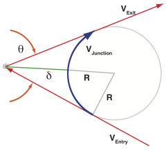
Given that @XDA-Bam looked at this extensively over the last period, do you see a reason why the extruder vector is part of this calculation?
Relevant sources:
[1] https://onehossshay.wordpress.com/2011/09/24/improving_grbl_cornering_algorithm/
[2] https://reprap.org/forum/read.php?1,739819
[3] http://blog.kyneticcnc.com/2018/10/computing-junction-deviation-for-marlin.html
swilkens
on 12 Jul 2020
No, I agree. I was wondering about this, too. I also suggested somewhere, that the extruder should be handled separately, but don't remember in which issue. I didn't want to change this, because I am not 100% sure why it (the E-value) was originally included and I suspect it might break some obscure feature/printer config when removed. At this point, it would be helpful if the original author of those lines could shed some light on this.
XDA-Bam
on 12 Jul 2020
Looks like we originally didn't include E, even had an option to exclude it which was enabled by default. But it was enabled by default here by @Sebastianv650
https://github.com/MarlinFirmware/Marlin/pull/10906
Lots of previous discussion on this here, mostly about connecting the junction speed at locations of axis speed jumps:
https://github.com/MarlinFirmware/Marlin/issues/9917
Reading through the history now, it's still strange to me.
swilkens
on 12 Jul 2020
Can we get the mods of @ShadowOfTheDamn into the planner for COREXY? Do we need more tests?
thierryzoller
on 31 Jul 2020
@thierryzoller: I have skipped through the two threads @swilkens suggested. It's not as easy as removing the extruder movement from the calculation. From what I understood, the problem was that Marlin used incorrect (too high/too low) junction speeds in JD when the extruder movement wasn't being taken into account. This affected some specific switches from retract/un-retract to print or travel moves.
Essentially, next_entry_speed is incorrect in those cases, because it also applies to extruder-only moves. At least as far as I understood the discussions in those threads. This is a problem of the current code structure and has to be rectified _before_ we take the extruder moves out of JD calculation. So, in the end, we have to handle extruder speed limits independently as suggested before by others and myself. Sadly, I currently don't have the time to look into this much further.
XDA-Bam
on 3 Aug 2020
This issue is stale because it has been open 30 days with no activity. Remove stale label / comment or this will be closed in 5 days.
![github-actions[bot] picture](https://avatars2.githubusercontent.com/in/15368?v=4&s=40) github-actions[bot]
on 3 Sep 2020
github-actions[bot]
on 3 Sep 2020
any news?
ShadowOfTheDamn
on 4 Sep 2020
@boelle : What's the conclusion on this issue? Is it actually resolved (which release?) or just something that can't be resolved right now?
Do you recommend sticking with CLASSIC_JERK or use JUNCTION_DEVIATION for Marlin 2.0.6?
 SidShetye
on 15 Sep 2020
SidShetye
on 15 Sep 2020
i dont know, i just added the stale label since "any news?" does not make much sense to remove the label
personal i dont use JD or any of the fancy new stuff, classick jerk etc works just fine
 boelle
on 16 Sep 2020
boelle
on 16 Sep 2020
Why are you doing this @boelle? Stale means people are completely ignoring things, that's obviously not the case here.
 sjasonsmith
on 16 Sep 2020
sjasonsmith
on 16 Sep 2020
This issue has had no activity in the last 30 days. Please add a reply if you want to keep this issue active, otherwise it will be automatically closed within 7 days.
github-actions[bot]
on 17 Oct 2020
Don't close. Bad bot 😉
XDA-Bam
on 24 Oct 2020
My issue was closed althought just related to this one.
Stuttering on Diagonal move with JD enabled and TMC2209 drivers
https://github.com/MarlinFirmware/Marlin/issues/20029
Video 1 : https://youtu.be/kngqQIPUP1c
_JD Enabled (See Diagonal Movement)
Video 2 : https://youtu.be/yOadfORpKuw
Classic Jerk Enabled (See - TMC 2209 Hybrid Threshold straight but noisy movement)
Bug Description
Having Junction Deviation enabled leads to stuttering XY Diagonal movements. See Videos below.
Disabling JD solves the issue.
Configuration Files
Marlin.zip
TMC2209 UART Mode
Hybrid Threshold (doesn't change the effect)
Additional Information
Video 1 : https://youtu.be/kngqQIPUP1c
_JD Enabled (See Diagonal Movement)
Video 2 : https://youtu.be/yOadfORpKuw
Classic Jerk Enabled (See - TMC 2209 Hybrid Threshold straight but noisy movement)
thierryzoller
on 6 Nov 2020
remove the extruder from JD calculations. That's the easiest way I can think of. extruder movements are only back and forth does not need JD.
ShadowOfTheDamn
on 6 Nov 2020
@ShadowOfTheDamn : I am not sure this is applicable, how would extruder movements influence the Diagonal XY move that stutters in my videos?
thierryzoller
on 7 Nov 2020
Removing E from JD calculations isn't directly the best solution to this. (see here https://github.com/MarlinFirmware/Marlin/issues/17342#issuecomment-657256980)
We used to not have E in JD but it caused a disconnect between local accelerations, causing sudden jumps.
This is still not a straightforward issue, sadly.
swilkens
on 7 Nov 2020
Just adding, I have the same setup (TMC2209) on my COREXY and I do not have these stuttering diagonal movements.
In case anyone needs bug testing when trying to improve the planner - I am available.
thierryzoller
on 11 Nov 2020
edit: gcode analyses turns out there was something strange in the gcode that i will investigate first...
Don't think this is the best place, but also don't know if it is worth for a new issue...?!
It is related to Junction_deviation, since I tested that and didn't solve the stuttering...: )
I am trying to optimize the speed of a large fdm printer (600x1000x600)mm by tuning marlin, but some things are not so clear to me and cannot find it in better/other github issues...
With the high res lines the motion is smooth (which is good...!!!) but with the lower res lines the moves are stuttering.
I noticed because the surface was very smooth when classic jerk enabled and pushed the speed up a lot and the surface was still smooth. The moves of the 'connect infill lines' are stuttering, and those line have less resolution.
What is happening, is jerk working on the high res lines and not on the low res lines?! or the other way around?!
Can this be theoretically resolved by changing the jerk and acceleration settings...?!
With JUNCTION_DEVIATION I also have in my case less quality than with 'classic' jerk enabled.
(small disclaimer, I still have to test the settings with 2.0.7.2 firmware, these results are with 2.0.5.3, I am trying to update to 2.0.7.2 to see if I get better result with 'arc-moves)
 rooiejoris
on 19 Nov 2020
rooiejoris
on 19 Nov 2020
Related issues
 ahsnuet09
·
3Comments
ahsnuet09
·
3Comments
 Matts-Hub
·
3Comments
Matts-Hub
·
3Comments
 StefanBruens
·
4Comments
StefanBruens
·
4Comments
 Anion-anion
·
3Comments
Anion-anion
·
3Comments
 Kaibob2
·
4Comments
Kaibob2
·
4Comments
Most helpful comment
Well, kinda both: Using true
acos()meansjunction_thetacan become greater than 2.96, thereby(RADIANS(180) - junction_theta)can get smaller than 0.18 and the speed "explodes", mitigating the issue for angles close to 180°. This is pretty much a race of 1/(angle difference) vs. block length. However, for angles closer to 135°, the block length will still be the issue from my understanding.Maybe we should look out for a better acos()-approximation AND think about handling the issue with alternating segments of vastly different length.