Circuitverse: TestBench Project
Currently the testbench is just a proof of concept. It can be found here - https://circuitverse.org/testbench.html
Some terms -
- Test Set - List of test cases
- TestBench Creator - A page which allows users to create test sets
- TestBench Element - Element within the simulator which does the actual testing
The current workflow is a bit awkward.
Create tests on testbench creator page
- Add Input and Outputs
- Add Tests
Create test element in Sumlator
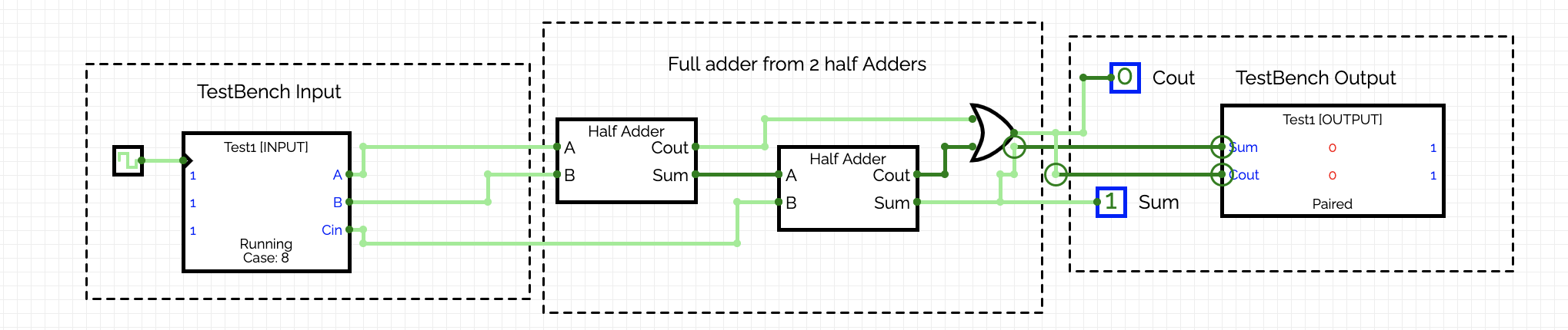
- create a testbench input and a test bench output elements. They are linked by the testbench name.
- Then double click on testbench input and enter the JSON from /testbench.html
- Run Tests
- Add Clock to testbench element
- Click TestBench Input
- Click Toggle State (in property menu)
- Test will start running
Should be noted that this is just for proof of concept. This entire thing should be rewritten. The exact workflow needs to be discussed and designed here.
This is what I have in mind -
Test Sets should be independent from the project. They should be saved as stand alone entitites similar to how projects are saved. This could be mean test sets can be reused across projects which has many benefits. This could also mean we can associate assignments with a testbench and that would mean students can create their circuit projects to pass the test cases set by teacher. Also allowing automated testing.
How exactly the project's testbench element is linked to the test set is something we need to decide.
Tests need to have the ability to be labeled and ordered. It should also have the ability to be grouped.
After discussion with @richardpawson, we came up with 3 different types of tests.
- Combinatorial tests -
- Similar to the current one - meant for combinational circuits
- Tests are not ordered because circuit is not stateful
- There should be a parameter called maximum circuit delay. The testbench element will just check if the total delay is less than the maximum circuit delay.
Sequential.
- Cases are in order - circuits are stateful
- Cases has to be grouped as a sequence of steps
- Reset Pin will trigger between each test set
- Clock column - Alternate rows are clock high and low respectively
- Delay for clock - There is a delay after the input after which the clock is triggered. This is required so that the circuit becomes stable
- Delay for circuit - Maximum delay for the entire circuit. This is to be calculted separately from the above clock delay
Timed.
- Inputs are defined as a waveform
- Need ability to specify the exact timing of all inputs and exact timing for all outputs
- Required in only very sophistacted and complex circuits
We should aim for type 1 and 2 first.
This is just the beginning, a lot more things can be done, would love to hear more ideas. We will need proper designs for the UI of the testbench creator and the TestBench Element as well. We also need to design the reporting system.
@richardpawson, @gr455 @sal2701 @Shivansh2407 any inputs here?
Are you working on this? (Yes/No)
No
 satu0king
All 8 comments
Test Sets
You captured my main point about the 3 types of test & I agree that 1 & 2 are the priority.
I agree about keeping test cases separate from the circuits for the reason you gave.
TestBench Creator
Personally,I wonder about the value of having our own TestBenchCreator. It is a lot of work for something rather generic. It worked OK for me, but I found it limited e.g.:
- Couldn't delete an Input or Output column I'd created by accident.
- Couldn't easily duplicate-then-edit cases
- Couldn't easily re-order (even if only for my own aesthetic reasons - ordering doesn't actually matter for combinatorial tests I agree.
For me, rather than create a richer TestBenchCreator, I would favour creating the test cases in Excel - it's a very good editor for this sort of thing and you c an save as .csv file. CV could a template .csv as an example, which would explain the conventions (e.g. column/row names if applicable).
I don't have a problem with having a CV TestBenchCreator tool - I just think it might be a waste of resources.
TestBench Element
I think the idea of the TestBench Element is fine. However ...
1) I don't see the value in having separate Input & Output elements. I would prefer just one element, which has both inputs and outputs, on the Left & Right sides of the element respectively. The element might need to be larger.
2) Have two options for running the tests:
Next test. This works similar to at present, when you add a clock pulse. Shows the input values next to the pins, and outputs (both expected and actual).
Run All. Shows up only Red (at least one has failed) or Green light (all- have passed just like the various Unit test frameworks). There would either then be a pop-up window listing the individual test results, or option to download it.
3) One quite frustrating thing at present is that each time you load a test set into the Element, it disconnects all the wires! I can see why that happens. This should be fixed by checking whether list of input/output pins from the new test set matches the _existing_ input/output pins on the element. If they do match, leave all wiring in place. If they don't match then fine to do what it does now.
 richardpawson
on 12 Dec 2020
richardpawson
on 12 Dec 2020
I agree with @richardpawson, the current TB input and output pair seems quite redundant. But since we plan to use tests across circuits (also automated). We could just get rid of the TB element and have the tests' input and output linked to the circuit's input and output through labels (the professor instructs the students to name inputs and outputs a certain way)
 gr455
on 12 Dec 2020
gr455
on 12 Dec 2020
I agree with @richardpawson, the current TB input and output pair seems quite redundant. But since we plan to use tests across circuits (also automated). We could just get rid of the TB element and have the tests' input and output linked to the circuit's input and output through labels (the professor instructs the students to name inputs and outputs a certain way)
@gr455
Not sure if labels is a good idea. It will not be very evident to the user. We can discuss this though. Another issue is design complexity.
satu0king
on 12 Dec 2020
@richardpawson Yes I think our testbench creator can simply have a load and download CSV option. The idea of the testbench creator is to do validation of things such as bitwidth. And also users might want to see their tests on the website, so we need a UI for the same. Yes we can actually make the UI read only. User can define the inputs, outputs and download a sample CSV. Then User can add tests and upload again.
Why are you particular about the testbench being one element instead of 2? The reason it is two elements is, in general inputs are on the left and outputs are on the right. So the circuit looks simple without wires crossing.
satu0king
on 12 Dec 2020
We could have a toggle in the property menu. Only input/output elements with toggle "Test" will be tested.
These elements will be visible in the TestBench Modal (which has to be created, like the one for timing diagram). Here we will generate a CSV template with values to be filled by the user or they can just upload a CSV file in the right format.
The results also need to be displayed in a better manner, a CSV file with the results might be good.
This could be the flow at a very high level. This wouldn't involve any TestBench Element to be placed and connected. Would reduce the workload for the user. Again have to look at design complexity, might not be easy to implement.
 sal2701
on 12 Dec 2020
sal2701
on 12 Dec 2020
@sal2701 and @gr455 both raised good points on using the labels for testing. Still a little skeptical but worth a try. We will need to try. The design is definitely more complicated though. The workflow for the user might be easy if everything goes correctly but I think it is harder if the user makes a mistake.
satu0king
on 12 Dec 2020
@satu0king you have mentioned about 'maximum circuit delay'. Didn't quite undertand that part. Why is it required and how will this work considering how we treat delays currently?
gr455
on 12 Dec 2020
@satu0king You asked 'Why are you particular about the testbench being one element instead of 2? The reason it is two elements is, in general inputs are on the left and outputs are on the right.'
I understand your argument for it being two elements, and I'm not wedded to it being one, but I find the idea of adding two elements separately, that are somehow, magically, _and invisibly_, linked together, not very intuitive. What happens if you drag in a second Input, or a second Output element, for example?
A single unified TestBench element could be positioned above, or below, the circuit being tested. That way the circuit inputs could be connected to the left side of the TestBench, the outputs to the right-side - no crossed wires.
Also TestBench sounds like 'a thing' (singular). In a physical circuit you'd say: 'put it on the test bench'. Having a TestBench_Input 'thing', and a TestBench_Output 'thing' doesn't sound right, semantically, to me.
Naming is a big thing for me in Computer Science, so I'm fussy about it. But if you decide to stay with two TB elements, that's OK.
BTW, I envisage using TestBench in two ways. While developing a circuit I would have the TestBench in the same tab as the circuit, to facilitate debugging. Once e.g. FullAdder was completed and all tests passing, I would then remove the TestBench from the FullAdder circuit, so it was cleaner, but create a new tab/circuit (e.g. called 'FullAdder_Test'), which contains just the TestBench connected to a FullAdder added as a self-contained - 'sub-circuit'. This would then act as a 'regression test' to be run as a check if another circuit, incorporating the FullAdder, showed a fault.
richardpawson
on 15 Dec 2020
Related issues
 mahmodHammad
·
8Comments
mahmodHammad
·
8Comments
 ankitkataria
·
4Comments
ankitkataria
·
4Comments
 tachyons
·
6Comments
tachyons
·
6Comments
 1337w0rm
·
3Comments
1337w0rm
·
3Comments
 jbox144
·
7Comments
jbox144
·
7Comments
Most helpful comment
Test Sets
You captured my main point about the 3 types of test & I agree that 1 & 2 are the priority.
I agree about keeping test cases separate from the circuits for the reason you gave.
TestBench Creator
Personally,I wonder about the value of having our own TestBenchCreator. It is a lot of work for something rather generic. It worked OK for me, but I found it limited e.g.:
For me, rather than create a richer TestBenchCreator, I would favour creating the test cases in Excel - it's a very good editor for this sort of thing and you c an save as .csv file. CV could a template .csv as an example, which would explain the conventions (e.g. column/row names if applicable).
I don't have a problem with having a CV TestBenchCreator tool - I just think it might be a waste of resources.
TestBench Element
I think the idea of the TestBench Element is fine. However ...
1) I don't see the value in having separate Input & Output elements. I would prefer just one element, which has both inputs and outputs, on the Left & Right sides of the element respectively. The element might need to be larger.
2) Have two options for running the tests:
Next test. This works similar to at present, when you add a clock pulse. Shows the input values next to the pins, and outputs (both expected and actual).
Run All. Shows up only Red (at least one has failed) or Green light (all- have passed just like the various Unit test frameworks). There would either then be a pop-up window listing the individual test results, or option to download it.
3) One quite frustrating thing at present is that each time you load a test set into the Element, it disconnects all the wires! I can see why that happens. This should be fixed by checking whether list of input/output pins from the new test set matches the _existing_ input/output pins on the element. If they do match, leave all wiring in place. If they don't match then fine to do what it does now.