Armory: node like line trace in unreal
you can make node like line trace in unreal it is very useful and very easy to use
 mhreez
All 11 comments
Hi, @mhreez. Armory already have a Physics Ray Cast node. It is the same that Line Trace.
You can put 2 emptys to represent the start and the end of the Ray Cast.
Use a Get Object and a Get Location node for each empty. Set Collision Filter to 1 in the Physics Ray Cast node.
Also, you can set a object to represent the hit location if you need.
It is really very useful, sadly it isn't working in Android :/
 knowledgenude
on 18 Apr 2020
knowledgenude
on 18 Apr 2020
thank you but I tried a lot with it but could not do that. Can you send a file that has been using the node in it?
mhreez
on 18 Apr 2020
The trait is commented like a tutorial.
*Make sure to set Collision filter in Ray Cast node settings to 1. I don't know why it comes with a zero by default.
Until now i don't know what the 'normal' value means... maybe it is the normal direction to get as a rotation. I will try it sometime.
Example here:
New Folder.zip
knowledgenude
on 19 Apr 2020
Until now i don't know what the 'normal' value means... maybe it is the normal direction to get as a rotation.
That's the normal vector of the surface at the hit position. This graphic shows it very well:
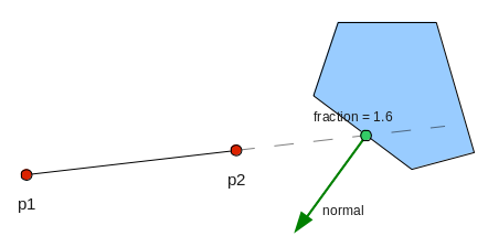
Image source: https://www.iforce2d.net/b2dtut/raycasting (not Armory related, I just searched for "ray cast normal")
Very nice eaxmple file by the way! Maybe open a pull request on the armory_examples repository?
 MoritzBrueckner
on 19 Apr 2020
MoritzBrueckner
on 19 Apr 2020
So, the normal vector can be used for stuff like that?
I don't understand too much by the image, it looks for me like a rotation value given by the normal direction.
So, I will make a pull request for this example, thank you @MoritzBrueckner!
knowledgenude
on 19 Apr 2020
I don't understand too much by the image, it looks for me like a rotation value given by the normal direction.
I'm not sure how much you know about vectors, but we are probably talking about the same thing. Basically, a vector is just a multidimensional value (like an array) that can represent a position or (in this case) a direction (so a 3d vector has x, y and z values). The normal vector is just the direction the surface at the hit position is "looking at". You can of course use this for rotation and it is like the rotation of the surface at that point, yes.
Usually the normal vector is "normalized", that means that it is an unit vector with a length of 1. The length sometimes doesn't really matter for directions but unit vectors make calculations more easy in many cases.
In the first image two posts above, the red points are on the ray line (the points actually don't matter here, the fraction neither does). That ray hits the polygon and the green normal vector represents the direction the face/edge that was hit is "looking at".
So, the normal vector can be used for stuff like that?
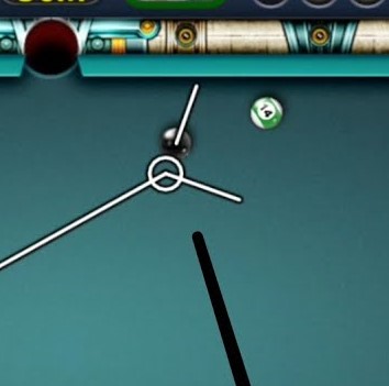
Yes :) For that particular example you would have to calculate the reflection of the ray's direction vector (that's the line coming from the left in the billard picture) off the normal vector and you would get the vector that is going to the right in the picture (the normal vector lays "in the middle" of both displayed lines. Actually it is a little bit more complicated in this case because there is a ball with volume and it's center point never hits the other ball but lets assume it is a ball with zero volume^^). Vector reflections are a little bit more complicated and I'm not sure if there is a node for it. It doesn't look like the Vector Math node supports it, I can open a PR for that tomorrow :)
If that wasn't clear, this is an image that explains reflections off a normal vector very well (on the left side):

Source: https://www.asawicki.info/news.php5?x=tag&tag=rendering&page=5
(i is the ray direction, n the normal vector (the plane could have another rotation for example) and the red vector is the reflected vector)
Sorry if this answer is a little bit overkill, I just try to explain it as good as possible :)
MoritzBrueckner
on 19 Apr 2020
I know that vectores can be way complicated. I find out when i tryed to understand how to get the distance between two objects. It is easy when you have just one vector, just subtracting the location of both objects in the world and getting the product that is the wanted distance. But when you have three vectors with positive and negative values... my brain is not advanced for this now.
Also, as you can see i don't know how to do a pull request. :/
knowledgenude
on 19 Apr 2020
Also, as you can see i don't know how to do a pull request. :/
It is described here: https://github.com/armory3d/armory/wiki/contribute
If I get the time I will add some more information to that wiki page :)
What you did is to create a pull request on your own fork and you merged the content of a branch of your fork to the master branch of also your fork. Instead you have to go to the Armory examples repository and open a pull request there. You should also unzip the file and put it in a folder instead, just as the other examples in that repository
MoritzBrueckner
on 19 Apr 2020
I will wait for the tutorial update. I tried to understand and follow it but seems that it was made for those who are already used to GitHub. Demonstrating the steps with images would also be interesting. Thank you for the informations.
knowledgenude
on 19 Apr 2020
Its updated now. More information is probably coming when I open a new PR sometime.
@mhreez Is this issue resolved now? If yes, you can close it :)
MoritzBrueckner
on 19 Apr 2020
Its updated now. More information is probably coming when I open a new PR sometime.
@mhreez Is this issue resolved now? If yes, you can close it :)
Thank you
mhreez
on 19 Apr 2020
Related issues
 AttSee
·
4Comments
AttSee
·
4Comments
 guzzard
·
4Comments
guzzard
·
4Comments
 Amir-Arsalan
·
4Comments
Amir-Arsalan
·
4Comments
 e1e5en-gd
·
3Comments
e1e5en-gd
·
3Comments
 Sanva
·
3Comments
Sanva
·
3Comments
Most helpful comment
I will wait for the tutorial update. I tried to understand and follow it but seems that it was made for those who are already used to GitHub. Demonstrating the steps with images would also be interesting. Thank you for the informations.