Zigbee2mqtt: Instruction for flashing firmware via Arduino
I have a positive experience of flashing firmware cc253x through Arduino without CCDebugger. Based on https://github.com/wavesoft/CCLib/issues/19#issue-260545038
Does it interest anyone? I can add the translation to the wiki, then edit the grammar. Or someone more experienced can make a translation.
 kirovilya
All 81 comments
I think would be great to have more flashing options. I just posted on the forum a way to flash using cc-tool (just seconds ago!): https://community.home-assistant.io/t/zigbee2mqtt-getting-rid-of-your-proprietary-zigbee-bridges-xiaomi-hue-tradfri/52108/176?u=ciotlosm
This is based on yet another great repo around CC2531 gateway emulation in C++ here: https://github.com/Frans-Willem/AqaraHub. That has a good tutorial on how to flash using cc-tool
 ciotlosm
on 31 May 2018
ciotlosm
on 31 May 2018
@ciotlosm It's great. cctool has an even better option, because in my case cclib it is necessary to slightly modify the firmware.
I'll try to flash through cctool and maybe delete my version, and leave them :)
kirovilya
on 31 May 2018
@kirovilya : Which Type of Arduino do you use ? I´m experiment via Nano V3.0 ATmega328P Micro-Board.
Btw: Here: http://magictale.com/2884/flashing-ble112-with-arduino-based-cc-debugger/ you will find an performance boosting Version but there we need to modifiy to add the CC253X Type.
 tb-killa
on 31 May 2018
tb-killa
on 31 May 2018
@ciotlosm Oh, no! I read that cctool uses ccdebugger :( so that flashing firmware through arduino will remain
kirovilya
on 31 May 2018
@kirovilya sorry for that. I was posting offtopic as I was just happy to see more options for flashing.
ciotlosm
on 31 May 2018
@tb-killa I uses Arduino Uno.
I seen this article, but can not check - need compiling with specific port...
@ciotlosm Don't worry :)
kirovilya
on 31 May 2018
Check out please https://github.com/Koenkk/zigbee2mqtt/wiki/Getting-started#22-via-arduinoesp8266
kirovilya
on 1 Jun 2018
@kirovilya you have to mention the needing of 3.3v on side of the usb Stick, because normaly you put an divider inside the connections. Or you use the internal resistor of the atmega themselve. I know it works without it but if some one broken the usb Stick you could say we mention it as an warning ;-)
tb-killa
on 1 Jun 2018
@tb-killa I refer to the instruction from CCLib and there it is mentioned about 5v on Arduino and 3.3v on the CC** chip. Probably, the chip can work with 5v, but I did not check it :)
kirovilya
on 1 Jun 2018
@kirovilya it works with esp8266 (wemos d1 mini) with changed pins. Maybe should be added to wiki?
 definitio
on 1 Jun 2018
definitio
on 1 Jun 2018
@definitio Did you test? Connection without resistors? What mean "changed pins"?
kirovilya
on 1 Jun 2018
@kirovilya yes, successfully flashed 1-2 weeks ago without resistors. I mean changed pins numbers.
definitio
on 1 Jun 2018
@definitio Good news! Thank you!
Added in wiki.
kirovilya
on 1 Jun 2018
Thanks for the instructions!
To keep the getting started as noob friendly as possible I've moved this to Alternative firmware flashing methods
 Koenkk
on 1 Jun 2018
Koenkk
on 1 Jun 2018
Good. I close the issue
kirovilya
on 1 Jun 2018
I've updated https://github.com/Koenkk/zigbee2mqtt/wiki/Getting-started with linux/macos instructions as well
ciotlosm
on 1 Jun 2018
@kirovilya in https://github.com/Koenkk/zigbee2mqtt/wiki/Alternative-firmware-flashing-methods you mention modified firmware for flashing via Arduino https://github.com/kirovilya/files/blob/master/CC2531ZNP-Pro-Secure_LinkKeyJoin_mod.hex
Is the above firmware different from the ones @Koenkk prepared? I'm trying to make sense and gather most of the firmwares in a logical place here: https://github.com/Koenkk/zigbee2mqtt-firmware for easier maintenance and linking.
ciotlosm
on 2 Jun 2018
@ciotlosm that firmware not made from Koen firmware. It make from any firmware by remove second line from end (as described here https://github.com/wavesoft/CCLib/issues/19)
kirovilya
on 3 Jun 2018
Would you be able to add this firmware to:
ciotlosm
on 3 Jun 2018
hi @definitio could you explain in detail which pins on the wemos d1 mini you connected to downloader cable?
I've tried different combination, but with no luck:
int CC_RST   = D4; // 2
int CC_DC    = D3; // 0
int CC_DD_I  = D2; // 4
int CC_DD_O  = D1; // 5
int CC_RST   = D7; // 13
int CC_DC    = D6; // 12
int CC_DD_I  = D5; // 14
int CC_DD_O  = D0; // 16
they both didn't work.
Thanks!
 maur8ino
on 9 Aug 2018
maur8ino
on 9 Aug 2018
@maur8ino just flashed the latest firmware (with removed the second line from the end) with this settings:
int CC_RST   = 5;
int CC_DC    = 4;
int CC_DD_I  = 14;
int CC_DD_O  = 12;
I am flashing according to your guide with Arduino Mega (5V board I suppose).
I was struggling with ./cc_info.py – response was always
ERROR: No chip found. Check your connection and/or wiring!
After I removed voltage divider (4.7 kΩ + 10 kΩ), it started working like a charm!
 mmithril
on 1 Sep 2018
mmithril
on 1 Sep 2018
Is it possible to flash via a NodeMCU 1.0 (ESP-12E)? It seems to flash okay but I always get an error when trying to run:
python27.exe cc_info.py -p COM9
ERROR: Could not find CCLib_proxy device on port COM9
The light on the NodeMCU turns on for a bit and then turns off.
 ericstewart22
on 27 Sep 2018
ericstewart22
on 27 Sep 2018
@ericstewart22
Were you successful with the NodeMCU? I got the same error :(
 HanschDennis
on 2 Oct 2018
HanschDennis
on 2 Oct 2018
@HanschDennis No, unfortunately not. I'll let you know if I get it working.
ericstewart22
on 2 Oct 2018
I have a Raspberry Pi so I think I will try this fork to flash
https://github.com/kabbi/CCLib-raspberry
ericstewart22
on 2 Oct 2018
I have a Raspberry Pi so I think I will try this fork to flash
https://github.com/kabbi/CCLib-raspberry
Did it work?
 larsdecker
on 18 Oct 2018
larsdecker
on 18 Oct 2018
Not yet. Verification fails and it doesn't go past 25% or 50%. The LED on the 2531 is off when I start flashing and turns on (green) a few seconds later, at the same time verification fails; I think it's a clue as to what is happening but I'm not knowledgeable enough to troubleshoot. I attached a screenshot of what it looks like, in case you're having the same issue, or in case someone else on here can help me troubleshoot.

ericstewart22
on 19 Oct 2018
At the moment, my USB Stick is still in the shipping process. I can try to look into the code, maybe i found something. I have only a little bit of experience of python. @ericstewart22 Can you please open a issue on the CCLib-raspberry project and post there a screenshot of the log? Maybe the maintainer of the project finds a solution for it.
On the main project of the CClib (https://github.com/wavesoft/CCLib) are resistances between the connections? @ericstewart22 Did you have resistances between your connections?
larsdecker
on 19 Oct 2018
@larsdecker
I don't see a way to create an issue in the CCLib-raspberry repo so I sent the developer an e-mail.
No, I didn't use any resistances because I don't think it's necessary and I'm not sure I have the resistors required. If I get this working I'll be sure to share what I learned.
ericstewart22
on 20 Oct 2018
Developer still hasn't responded. Anyone else have any tips?
ericstewart22
on 26 Oct 2018
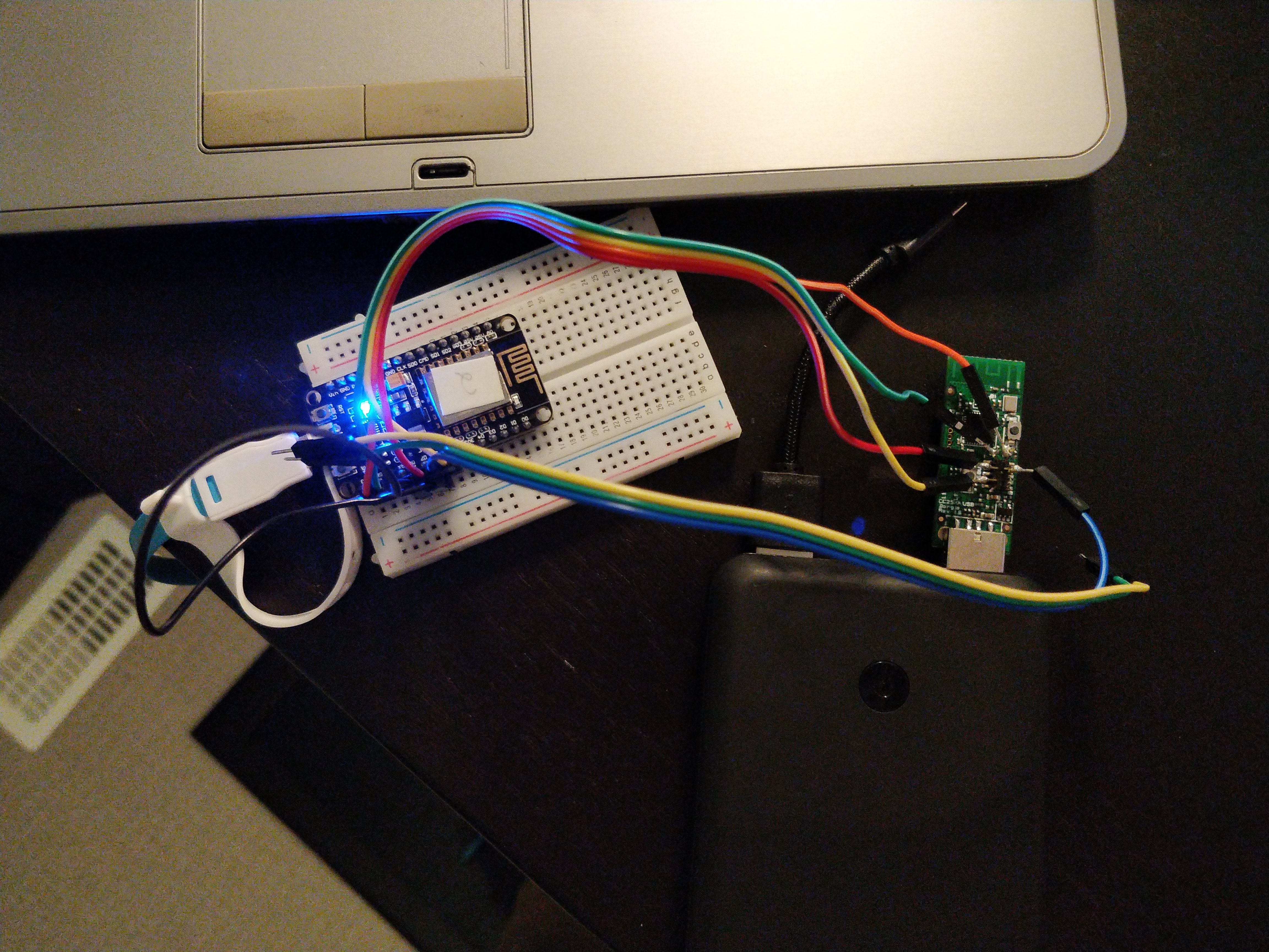
Okay, I finally got it working with my NodeMCU v1.0. I gave up on the Raspberry Pi. I listed my setup below and some notes so that others don't have to struggle with this as well.
Windows 10 Pro 64-bit fresh install on old laptop
Arduino 1.8.7 installed, not portable, with default drivers for NodeMCU 1.0
Python 2.7 fresh install, added to PATH
pip install pyserial==3.0.1
CCLIb from here:
https://github.com/kirovilya/CCLib
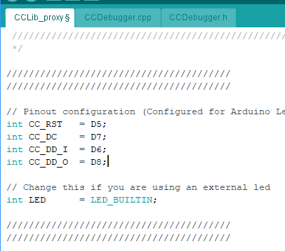
CCLib_proxy.ino modified to use these pins:
int CC_RST   = D5;
int CC_DC    = D7;
int CC_DD_I  = D6;
int CC_DD_O  = D8;
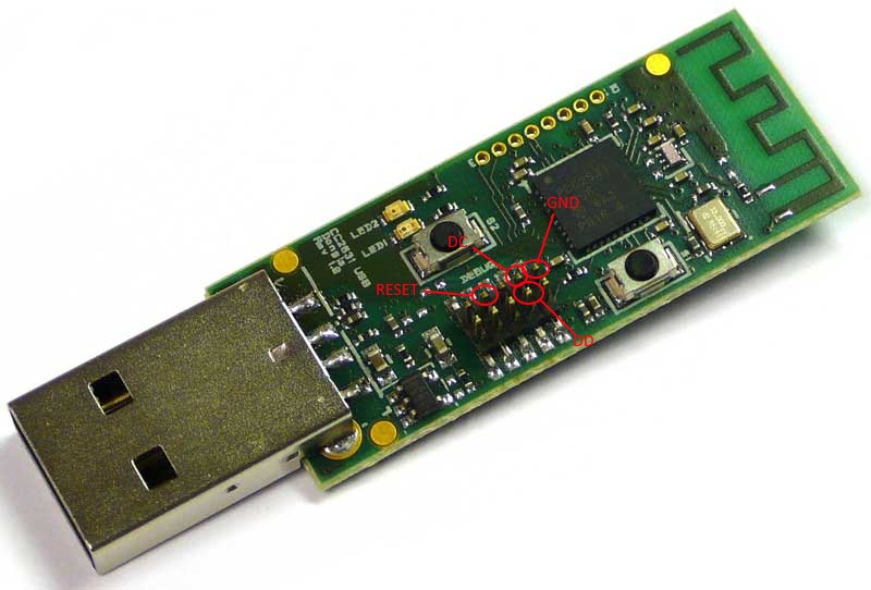
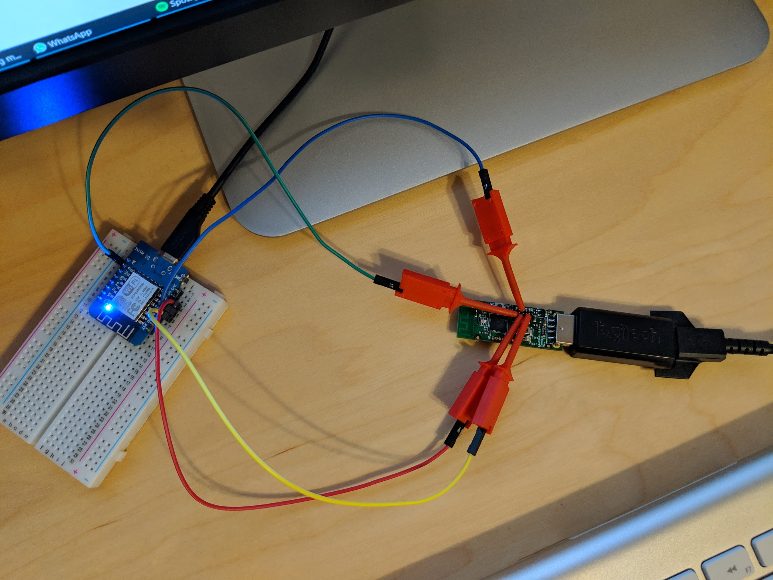
Pins connected as follows (see attached image)
ORANGE         3.3V VCC     3.3
GREEN          GND          GND
YELLOW         RESET        D5
BLUE           DBG DATA     D6
RED            DBG CLOCK    D7
I connected pins D6 and D8 on the breadboard (BLACK wire)
No resistors, I think because all NodeMCU's 1.0 pins are 3.3v instead of the 5v on Arduino.
CC2531 was plugged into USB port for power during flashing. Picture shows power bank but I used my laptop's USB ports in the end.
Flashed this firmware:
https://github.com/kirovilya/files/blob/master/CC2531ZNP-Pro-Secure_LinkKeyJoin_mod.hex
With this command:
python cc_write_flash.py --in=CC2531ZNP-Pro-Secure_LinkKeyJoin_mod.hex --erase
Green light on CC2531 should stay off during flashing.
It was very slow, it ran overnight. You can use Window's Presentation Mode to try and make sure your computer doesn't go to sleep or turn off overnight (Ctrl + X, Mobility Centre).
ericstewart22
on 27 Oct 2018
Thanks a lot for your detailed report. My cc2531 is still in the shipping.
After a received my, i will try your approach with the nodemcu.
larsdecker
on 29 Oct 2018
Just a short question: Is it possible to use an arduino nano V3 for flashing the CC2531?
Thanks in advance.
 derchrome
on 29 Oct 2018
derchrome
on 29 Oct 2018
In my opinion it should possible. But i have no experience with it.
The internal storage of the arduino nano is a little bit low. Maybe that is a problem.
The esp8266 / esp32 are very cheep and powerful. So if the arduino nano is not workling then you can try it with the esp´s.
larsdecker
on 29 Oct 2018
Do you mean something like that:
https://rover.ebay.com/rover/0/0/0?mpre=https%3A%2F%2Fwww.ebay.de%2Fulk%2Fitm%2F252718027546
derchrome
on 29 Oct 2018
Yes, the esp32 / esp8266 works for a lot of electronics projects.
The esp32 is a new chip and it is more powerful and has support for bluethooth / ble. For flashing the cc2531 both should work.
larsdecker
on 29 Oct 2018
So I shall order the NodeMcu from eBay?
derchrome
on 31 Oct 2018
When you need it fast, it will be okay, for that price.
Otherwise you should order it directly from china.
Sometimes the price are around 1,20 € for the esp8266
For example:
https://de.aliexpress.com/item/ESP8266-CH340G-CH340-G-NodeMcu-V3-Lua-Wireless-WIFI-Module-Connector-Development-Board-Based-ESP-12E/32800966224.html?spm=a2g0x.search0104.3.45.38434e9111Xv5W&ws_ab_test=searchweb0_0,searchweb201602_3_10320_10065_10068_5731315_10547_319_317_10548_5728815_10696_10084_10083_10618_10304_10307_10820_5731115_10821_10302_5731415_5731215_5731615_10843_328_10059_10884_5731515_10887_100031_10319_321_322_10103_5731715,searchweb201603_1,ppcSwitch_0&algo_expid=e6c69a84-45ba-46b6-b686-c21df581bd16-9&algo_pvid=e6c69a84-45ba-46b6-b686-c21df581bd16
The esp32 are a little bit more expensive, but has much more power.
larsdecker
on 1 Nov 2018
@derchrome I succesfully flashed it with a Arduino Nano. It took about 4 hours and it was tricky to get everything in the right (flash-)mode.
HanschDennis
on 2 Nov 2018
@HanschDennis
Do you have any details about the settings you made? Can you please post it here?
derchrome
on 2 Nov 2018
I have managed to do it according to @ericstewart22 s instructions. If it doesn't work on first try, try disconnecting and connecting MCU to computer try disconnecting and connecting CC2531 to computer. In the end I don't have 3v3 connected and it works.
 drndos
on 10 Nov 2018
drndos
on 10 Nov 2018
@drndos
Did you use the Nano also? My CC2531 arrived yesterday :-)
derchrome
on 11 Nov 2018
@derchrome
I Tried using Arduino Mega, Wemos R1 mini and Node MCU. I managed to make it working with Node MCU (maybe others would work if I put more time to it). In all cases I got to a point where it would say that the chip is not responding. Only after few hours and rewiring everything again and again and checking everything I got to point of despair and started plugging it on and off in different order and got it working at last with Node MCU (because I believed it must be working somehow because of that picture and instructions from @ericstewart22 ) .
I have not tried it with nano, but I would suggest trying:
Same mapping as in instructions based on the pinout.
Don't be afraid of using constants D8, D6 ... in your program.
- Try not connecting 3v3
- Try connecting arduino and CC2531 to computer in different orders (I saw that my Node MCU didn't light up when connected in wrong order). Try reconnecting.
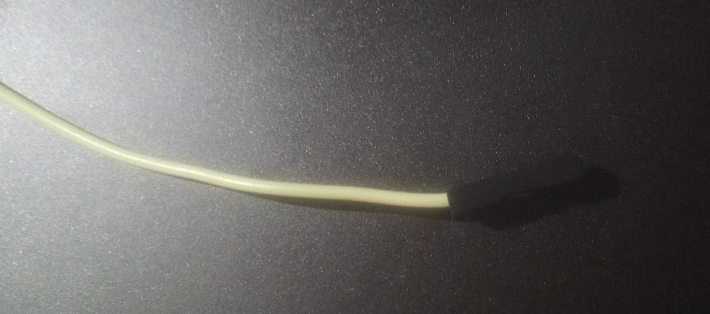
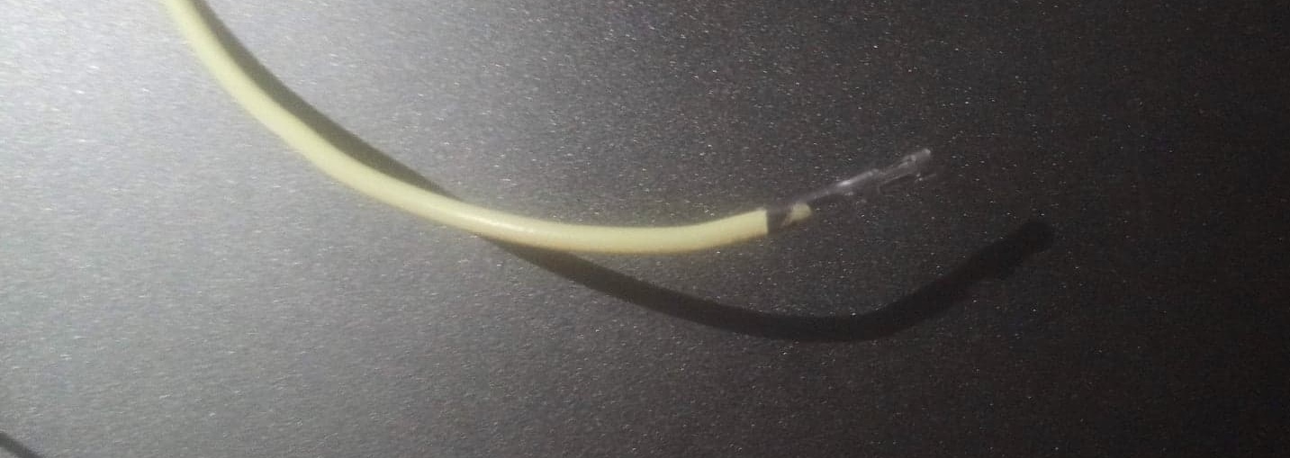
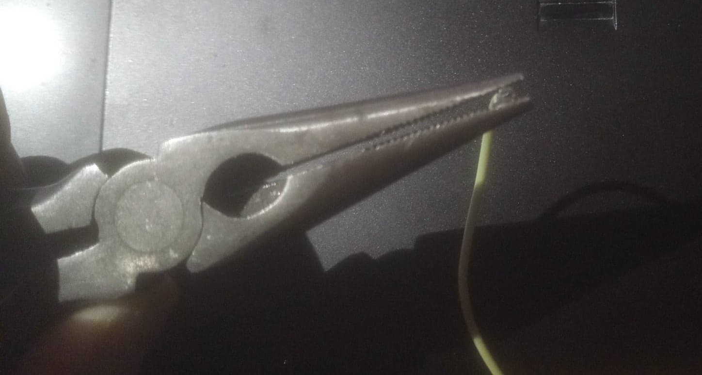
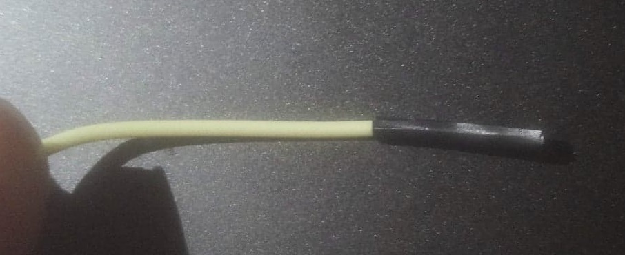
I didn't have proper cable, so I created some ghetto cables from arduino jumper wires by removing the plastic cover on one end and squishing the hole to smaller one and isolating it with isolating tape.
I have increased the timeout but I am not sure if it helped
- Try connecting the DD wire like this D8 -- D6 -- DD and not like D6 -- D8 -- DD (I have no idea if it can make a difference)
- In my case the LED on NodeMCU was ON and LED on CC2531 was OFF for some reason.
drndos
on 11 Nov 2018
I have this is error (ERROR: Could not find CCLib_proxy device on port COM5)
 RssFra97
on 17 Nov 2018
RssFra97
on 17 Nov 2018
My stick is also here. I will try it on the weekend. Hopefully i have luck with that.
Thanks also @drndos for the great instruction.
larsdecker
on 20 Nov 2018
I have this is error (ERROR: Could not find CCLib_proxy device on port COM5)
I have the same error, any ideas?
derchrome
on 7 Dec 2018
The wiring is very complicated, because it is very small. I have broken the GND Pin 😂. Anyone has an Idea how i can connect the GND with another pin?
larsdecker
on 15 Dec 2018
Hello, same thing happened to me. I managed to solder small wire to the base of the gnd pin. Since it takes several hours to complete I would not recommend holding it there.
drndos
on 15 Dec 2018
python2.7 cc_info.py -p /dev/cu.wchusbserialfd120
ERROR: Could not find CCLib_proxy device on port /dev/cu.wchusbserialfd120
I'm using a Wemos D1 mini on macOS, but somehow it already doesn't answer to the ping.
Is there some option I need to pay attention to when flashing? Other sketches worked fine so far.
 vogler
on 19 Dec 2018
vogler
on 19 Dec 2018
So for me it worked now! After trying several things like reconnecting both, the NodeMcu and the CC2531 in different orders, rechecking the wiring and so on, it finally worked. I disconnected the CC2531 from the PC and connected it to a usb 5v power supply. When I connected it to the power supply the green led on the CC board was off and I could directly flash the board! Before (when connected to the PC) the led has been on all the time and flashing was not possible.
Maybe this helps somebody with similar problems.
derchrome
on 19 Dec 2018
I can recommend these test hook cables - very quick and painless. Currently flashing 🤞
Some other notes: under macOS on two different MBPs I just got ERROR: Could not find CCLib_proxy device. On my Windows Desktop the Wemos D1 mini responded correctly. However I had to add -E for cc_info.py to work. Also, as @derchrome mentioned, USB data connection on the CC2531 side seems to be a problem: with a power bank everything worked (but turned off after some time), plugging it in the PC, the Wemos went down - I then only plugged it in enough for the power pins.
vogler
on 19 Dec 2018
I just spent several hours trying to fix the ERROR: No chip found. Check your connection and/or wiring! message I was getting and thought I'd give hints about how I finally got it work. The whole procedure seems to be very temperamental, so it requires patience (if you aren't lucky).
I originally tried with a 3.3 V WeMos D1 mini with DD_I and DD_O pins connected together, but that still gave an error. Next I tried a 5 V Arduino Leonardo with the resistive level converter, but that gave the same error. Finally I tried a NodeMCU using the same pinouts as @drndos above, which again gave the same error but I was eventually able to get CClib to recognize my CC2531.
I'm not exactly sure what fixed it, but here are a few points that might help:
- Try disconnecting either the
DD_IorDD_Opin on your Arduino before powering it up - Increase the timeout in the Arduino sketch to 1000 ms (the
delay()statement) - Plug the CC2531 into a USB power supply instead of the host PC
- Switch the order in which you power on the Arduino and the CC2531
- Try a different PC + OS (Windows didn't work, Ubunutu did)
- CClib seems to work with Python 3.6, but I did use the old version of pyserial that was recommended
- I noticed that some of the data pins from the CC2531 had 3.3 V on them after plugging them it, might be useful to check for that after you wire everything up
 roger-
on 27 Dec 2018
roger-
on 27 Dec 2018
- Increase the timeout in the Arduino sketch to 1000 ms (the
delay()statement)
This is actually the trick.
Increase the timeout to 5000.
Unplug power from the CC2531 dongle but keep it connected to the ESP.
Reset / power on the ESP.
Now within these 5 seconds power up the CC2531.
Done.
If the CC2531 is powered up then the ESP won't boot.
If the CC2531 is not powered up while the ESP inits the debugger it won't work.
So put a 5 second delay there, power up the ESP then power up the CC2531 and both problems are solved.
I had to use Python2 and run the script as root btw.
 BotoX
on 1 Jan 2019
BotoX
on 1 Jan 2019
Hello,
I have as well the CC2531 and try to manage flashing using an Arduino micro (5V). Connection is without resistors in between (seems to be no "killer"). The CC2531 is connected to a 5V USB power supply (Samsung 2,2 A max). The DD is connected like 2 (==D8 -> DO) -- 3 (==D6) -- DD (I tried different order as well, this one was the most stable).
Best results are with following connection order: unplug both, then 1st Arduino and within 5s (changed delay accordingly) the CC2531.
cc_info.py shows promising results:

Also cc_read_flash.py worked flawless, I dumped the original flash successfully.
BUUUTTT here comes the catch... cc_write_flash.py is not working with:
sudo python2.7 cc_write_flash.py -p /dev/tty.usbmodem141301 --in=CC2531ZNP_Kirovilya_mod.hex --erase

Any suggestions how this can be resolved?
 janisHD
on 11 Jan 2019
janisHD
on 11 Jan 2019
To all with similar problems:
I could resolve the issue with setting the baudrate to 1200 kpbs, any baudrate higher than that leads to a known issue:
https://github.com/arduino/ArduinoCore-avr/issues/53
After making the changes in the .ino and ccproxy.py the flashing works flawlessly and within a few minutes!
Regards
janisHD
on 19 Jan 2019
Not that easy, to flash that stick. I now try it with the nodeMCU with no luck. When i try to check the values the nodeMCU seems to be go off (the blue led goes off). The green LED of usb stick is on. Have anyone some tricks how it work with the nodeMCU Amica?
larsdecker
on 19 Jan 2019
Have a look at https://hackaday.io/project/163487-zigbee-cc2531-smart-home-usb-adapter
There's a nice tutorial covering a complete install using an ESP8266 / Wemos D1 mini as a programmer.
 creativtransfer
on 20 Jan 2019
creativtransfer
on 20 Jan 2019
I'm close to giving up: after fighting with my CC2531 sticks for weeks, I'm finally able to flash more than 85%, but then I'm getting reproducibly an error:
Flashing:
-- Chip erase...
-- Flashing 4 memory blocks...
-> 0x0000 : 8176 bytes
Progress 100%... OK
-> 0x1ff6 : 10 bytes
Progress 100%... OK
-> 0x3fff0 : 1 bytes
Progress 100%... OK
-> 0x2000 : 239616 bytes
Progress 91%... ERROR: Could not read from the serial port!
I'm using an Arduino nano and I'm getting the same result on a MacBook and an Ubuntu desktop. I've played with the baud rates, but no success with 1200,4800,19200.
Any ideas why the flashing works properly for hours and then suddenly fails just shortly before finishing?
 druxx
on 28 Jan 2019
druxx
on 28 Jan 2019
hooray, I was able to flash my first CC2531.
Had to increase the read timeout from 3secs to 10secs. I've tried this before, but at at different baud rates. The whole thing is really a little bit tricky
druxx
on 29 Jan 2019
Good to hear you've made it.
Where exactly did you increase the timeout? Please post the relevant lines of code...
And which firmware have you installed now?
CC2531ZNP-Prod.hex
or
CC2531ZNP-Pro-Secure_LinkKeyJoin_mod.hex
creativtransfer
on 29 Jan 2019
finally I was able to flash my two CC2531 with CC2531ZNP-Pro-Secure_LinkKeyJoin_mod.hex (and they work as expected).
My setup:
Ubuntu 18.04 Desktop
Arduino Nano V3.0
voltage divider 2.2k / 3.9k to be on the safe side, 100k / 200k doesn't work since the CC2531 has pull-up resistors
CC2531 USB stick
Chip ID : 0xb524
Flash size : 256 Kb
Page size : 2 Kb
SRAM size : 8 Kb
USB : Yes
I had to increase the read timeout on the Python side for the serial transfer to a ridiculous high number of 20secs:
line# 85 in cclib/ccproxy.py:
self.ser = serial.Serial(port, baudrate=9600, timeout=20.0, write_timeout=3.0)
(Symptons with the default timeout of 3secs: the flashing stopped a dozen times after having flashed more than 85% with a read timeout on the serial transfer)
contrary to other reports here I had no success with other baud rates (tested: 1200,4800,19200)
druxx
on 1 Feb 2019
I've followed exactly what @drndos did with a Wemos D1 mini (followed his pin configuration and his cable solution also) and @BotoX recommendation for a delay of 5000ms and was able to flash it just under 2 hours. Wemos was connected on my laptop with Windows 10 and the usb-stick was on a 5V 2 amp USB power supply. If errors on chip detection, check cables. Led lamp on CC2531 has to be off.
Hope this bit of information will help someone as it wasn't easy to follow all the different possible configurations.
I would also like to thanks @drndos for his pictures. It helped tremendously!
 way2many
on 7 Feb 2019
way2many
on 7 Feb 2019
Hi - none of the links for getting started, alternate flashing methods etc work anymore :(
 timdonovanuk
on 14 Feb 2019
timdonovanuk
on 14 Feb 2019
Have you checked https://hackaday.io/project/163487-zigbee-cc2531-smart-home-usb-adapter ?
This is kind of a tutorial on how you do it with an ESP8266/nodeMCU/wemos d1 mini but it's basically the same for any other arduino compatible device. You just have to adjust your programming pins accordingly...
creativtransfer
on 14 Feb 2019
After weeks of trying, finally got the flash working with @vogler 's recommendation to use test hook cables. In earlier failed attempts: I improvised with Bus Pirate probe cable, nodeMCU v3, Arduino Mega...
I used a nodeMCU v2 with the following pinouts:
int CC_RST   = D5;
int CC_DC    = D7;
int CC_DD_I  = D6;
int CC_DD_O  = D8;
The Arduino sketch used these values
// Initialize serial port
  Serial.begin(9600);
  // Wait for chip to initialize
  delay(5000);
and I also incorporated @druxx 's idea to increase timeout in cclib/ccproxy.py:
self.ser = serial.Serial(port, baudrate=9600, timeout=20.0, write_timeout=3.0)
And I confirmed what others have mentioned, the LED on the CC2531 will stay off while the nodeMCU's LED is on during flashing. I powered CC2531 with a Samsung phone charger.
EDIT:
Connection for DD: D6 -- DD -- D8 and surprisingly the flash time wasn't as long as I expected since others mentioned it took more than 2 hours. Mine took just over an hour and my estimate was 1.3 hours.
 AS137430
on 16 Feb 2019
AS137430
on 16 Feb 2019
What do you want to use for flashing? Arduino uno, nano, nodemcu, wemos d1 mini?
You have to look in your code, there you'll find something like this:
...
// Pinout configuration (Configured for wemos D1 mini)
int CC_RST = D5;
int CC_DC = D7;
int CC_DD_I = D6;
int CC_DD_O = D4;
...
In this case, it's for a wemos d1 mini, so just hook it up to the corresponding pins named D4, etc.
creativtransfer
on 27 Feb 2019
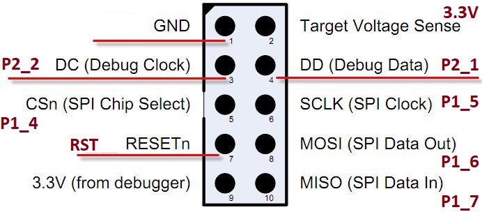
I figured it out, but the problem with ambiguous instructions...the following diagram looks a lot like the debug cable, except its not, it represents the direct pins on the actual board:

If you're using the debugging cable (mine anyway) its actually (with the red cable strip at the bottom and the clip of the cable to your left, denoted by the indent)....:

Or to put it another way humans understand:

timdonovanuk
on 27 Feb 2019
tried flashing a cc2530 via nodemcu with baud 9600 delay in arduino sketch, and readtimeout:20 write_timeout:3 for serial in ccproxy.py
Sadly i only get the following:
Flashing:
- Chip erase...
- Flashing 4 memory blocks...
-> 0x0000 : 8176 bytes
Progress 100%... OK
-> 0x1ff6 : 10 bytes
Progress 0%... ERROR: Flash verification error on offset 0x1ff6
edit: I tried that a few times now...do I need an external power supply for the chip, because atm i power the cc2530 via the 3.3v pin of the nodemcu
 fluffymadness
on 7 Mar 2019
fluffymadness
on 7 Mar 2019
@fluffymadness : Most of the other attempts seem to use separate power supply. You can try powering from PC/laptop USB and disconnect 3.3V of nodemcu.
Or you might want to try CCLoader #1057
https://github.com/Koenkk/zigbee2mqtt/issues/1057#issuecomment-468920302
https://github.com/Koenkk/zigbee2mqtt.io/blob/dev/information/alternative_flashing_methods.md
AS137430
on 8 Mar 2019
Thx.
I got it running by flashing it via teensy 3.1 and external power supply.
Whats interesting...flashing via teensy only takes about 2minutes not 2 hours like listed.
fluffymadness
on 8 Mar 2019
EDIT: I Take it back this did not work, CCLoader says its working but is actually doing nothing, I may have had a dead chip, will update once replacements arrive
**FINAL NOTE: The chip was dead a replacement CC2531 and Programmer, got me up and running, for those of you in Australia you can use the 40mm Test Clips from Jaycar and they do the trick


**
Just to let people know who are looking CCLoader works very well with flashing a CC2530 via an ESP8266 (NodeMCU v3), using this fork, instructions and connection diagram
https://github.com/jeanniquini/CCLoader
https://github.com/Koenkk/zigbee2mqtt.io/blob/master/information/alternative_flashing_methods.md


 sparky3387
on 24 Mar 2019
sparky3387
on 24 Mar 2019
I know this has been closed but I didn't know where else to ask for help. I followed the instructions from https://hackaday.io/project/163487-zigbee-cc2531-smart-home-usb-adapter and everything seemed to be working but the information I gotten from the CC2531 was different to everyone else's. Is this likely a faulty unit or is there something I'm missing? I am using a nodemcu 8266 board.
C:\CCLib-master\Python>python cc_info.py -E -p com16
INFO: Found a CC2531 chip on com16
Chip information:
Chip ID : 0xb524
Flash size : 16 Kb
Page size : 2 Kb
SRAM size : 1 Kb
USB : No
Device information:
IEEE Address : 000000000000
PC : 0000
Debug status:
[ ] CHIP_ERASE_BUSY
[ ] PCON_IDLE
[X] CPU_HALTED
[ ] PM_ACTIVE
[ ] HALT_STATUS
[X] DEBUG_LOCKED
[X] OSCILLATOR_STABLE
[ ] STACK_OVERFLOW
Debug config:
[ ] SOFT_POWER_MODE
[ ] TIMERS_OFF
[ ] DMA_PAUSE
[ ] TIMER_SUSPEND
 Tekno-man
on 1 Aug 2019
Tekno-man
on 1 Aug 2019
The memory size details look somewhat strange. It should have 256kB of flash. Maybe it's just reporting a wrong value, because the flash is inside the CC2531 chip.
But since it was recognized by cc_info.py I'd just give it a try and flash it...
Can you post a photo of your device?
creativtransfer
on 1 Aug 2019
I did try this and unfortunately I got the error "data to bit to fit fit in chips memory" which makes it sense as the read out says only 16kb of space!
Tekno-man
on 1 Aug 2019
I'll have to take a photo tonight. Thanks for responding by the way, appreciate the advice.
Tekno-man
on 1 Aug 2019
Actually, there are two devices with 16kB flash: cc2510 and cc2511.
However, these should have different chip IDs
Am 01.08.2019 23:52, schrieb Tekno-man:
I'll have to take a photo tonight. Thanks for responding by the way,
appreciate the advice.
creativtransfer
on 2 Aug 2019
Hmmm, Im pretty sure on the top of the chip 256 was written also. This is the product I bought https://www.banggood.com/Wireless-Zigbee-CC2531-Sniffer-Bare-Board-Packet-Protocol-Analyzer-Module-USB-Interface-Dongle-p-1227206.html?rmmds=myorder&cur_warehouse=CN
Tekno-man
on 2 Aug 2019
Here are the images of my set-up


Tekno-man
on 2 Aug 2019
So I tried flashing with ccloader and it seems to have worked
Tekno-man
on 15 Aug 2019
So I tried flashing with ccloader and it seems to have worked
How did you do it?
I´m trying to flash it with cc_write_flash.py but it says: "ERROR: Data too bit to fit in chip's memory!"
With cc_info.py i got this:
Chip information:
Chip ID : 0xb524
Flash size : 16 Kb
Page size : 2 Kb
SRAM size : 1 Kb
USB : No
Device information:
IEEE Address : 000000000000
PC : 0000
 marcodlima
on 23 Oct 2019
marcodlima
on 23 Oct 2019
Related issues
 rm2kdev
·
3Comments
rm2kdev
·
3Comments
 LCerebo
·
3Comments
LCerebo
·
3Comments
 z4rn0x
·
3Comments
z4rn0x
·
3Comments
 ophilips
·
4Comments
ophilips
·
4Comments
 mpuff
·
3Comments
mpuff
·
3Comments
Most helpful comment
This is actually the trick.
Increase the timeout to 5000.
Unplug power from the CC2531 dongle but keep it connected to the ESP.
Reset / power on the ESP.
Now within these 5 seconds power up the CC2531.
Done.
If the CC2531 is powered up then the ESP won't boot.
If the CC2531 is not powered up while the ESP inits the debugger it won't work.
So put a 5 second delay there, power up the ESP then power up the CC2531 and both problems are solved.
I had to use Python2 and run the script as root btw.