https://github.com/dirkwhoffmann/vAmigaTS/tree/master/Interrupts/int/int1
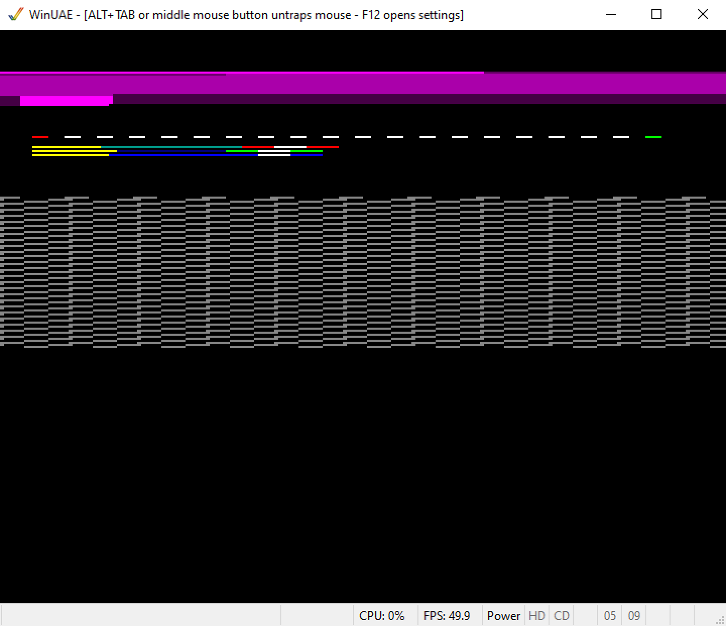
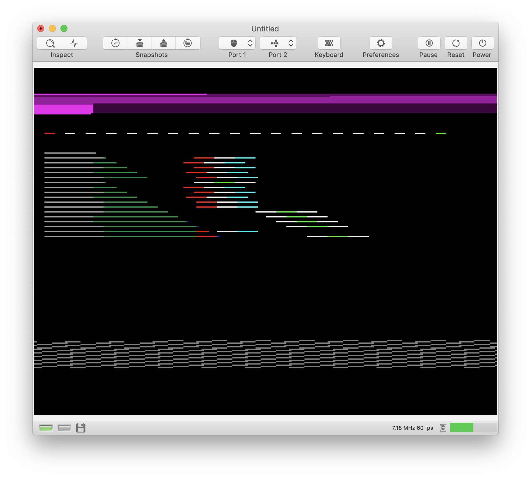
Background: This test syncs the CPU in the upper part of each frame (magenta area). Syncing is done to get reproducible images. It causes the CPU to be at the beginning of a specific instruction when a certain raster position has been reached. After that, the Copper is utilized to trigger a level 1, level 2, and level 3 interrupt. Each interrupt handler draws a color stripe. To improve visualization, I redirect the stack pointer to the color registers which causes the background color to change when certain elements of the stack frame are written (of course, I have to return from the interrupt handler manually, because I cannot use the color registers as a real stack).
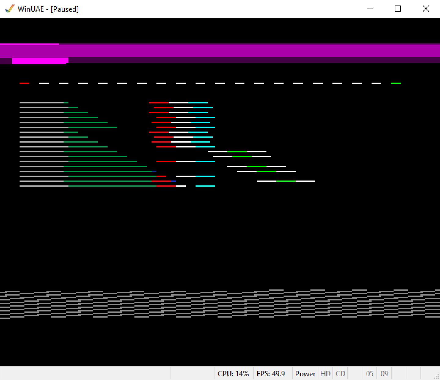
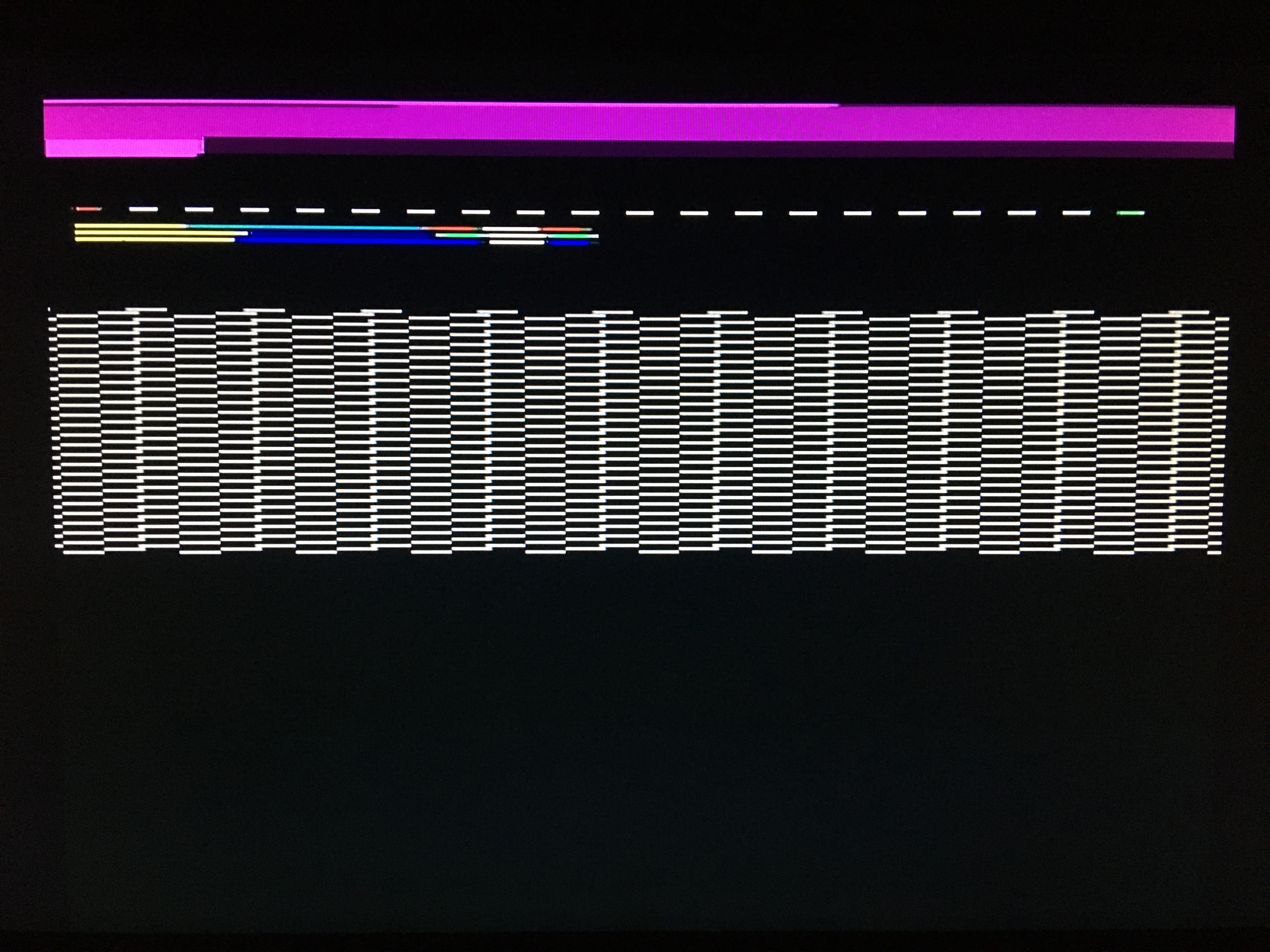
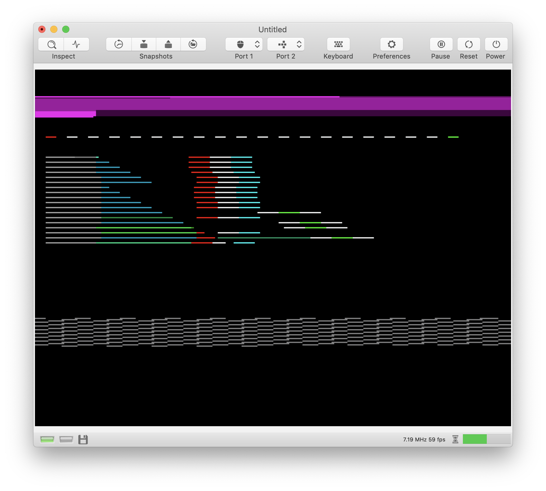
This is what UAE produces for my test case:
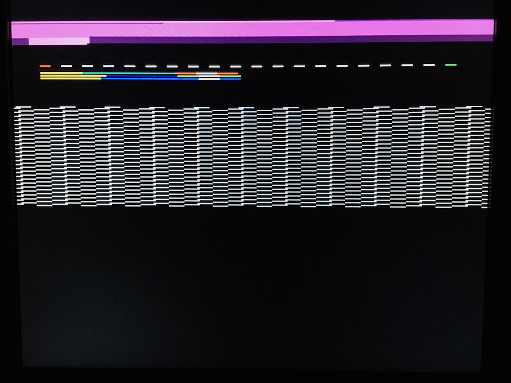
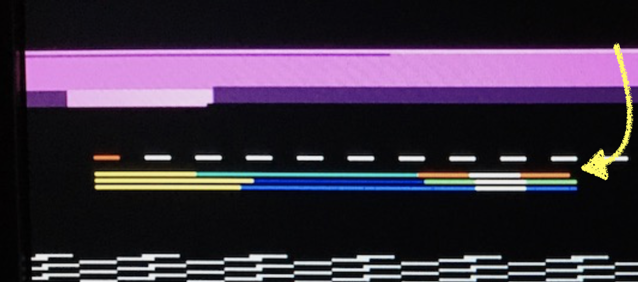
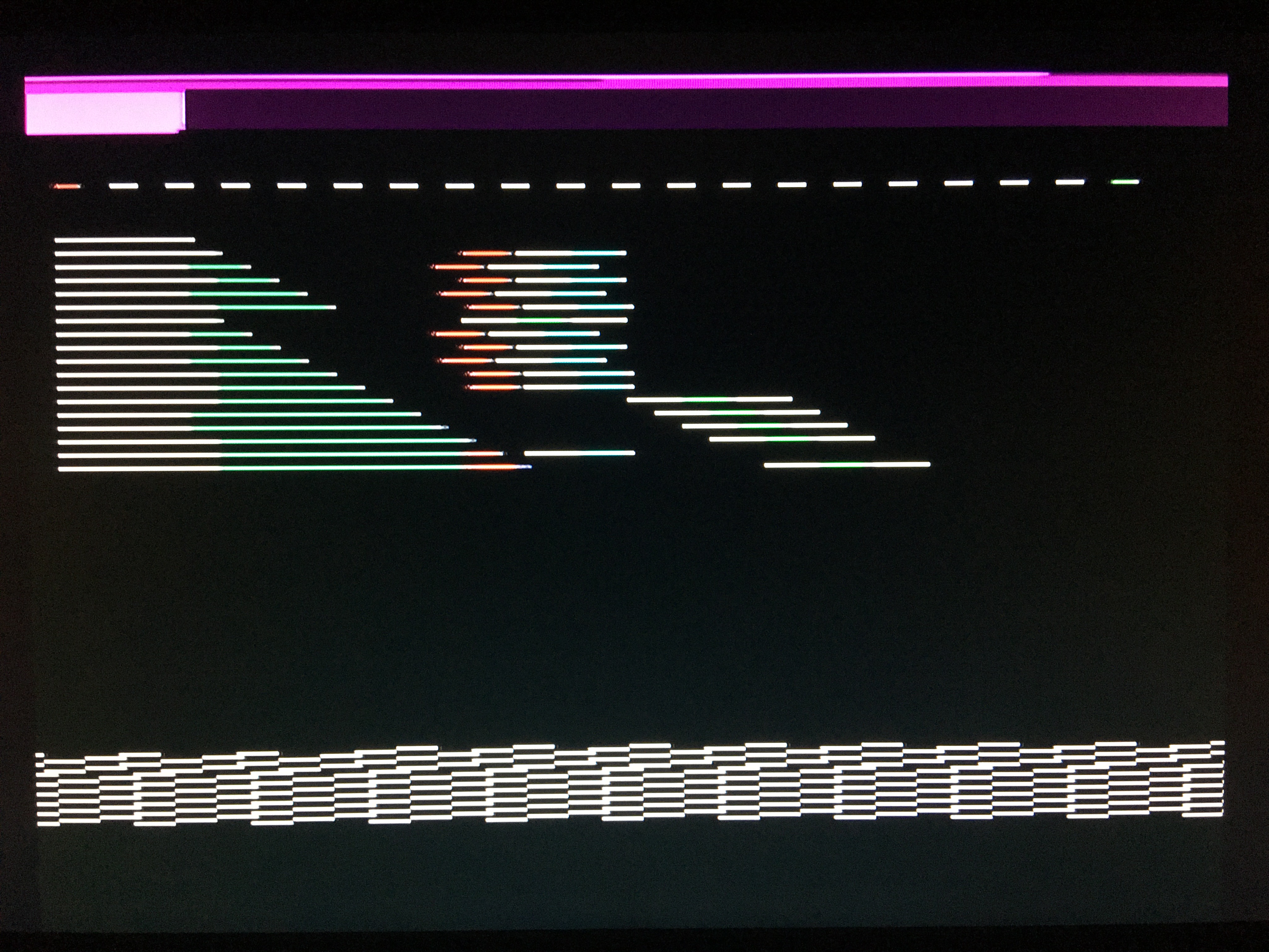
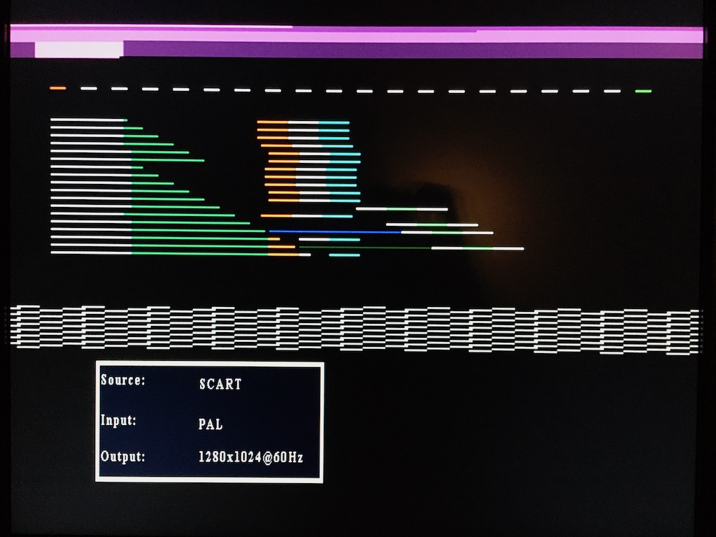
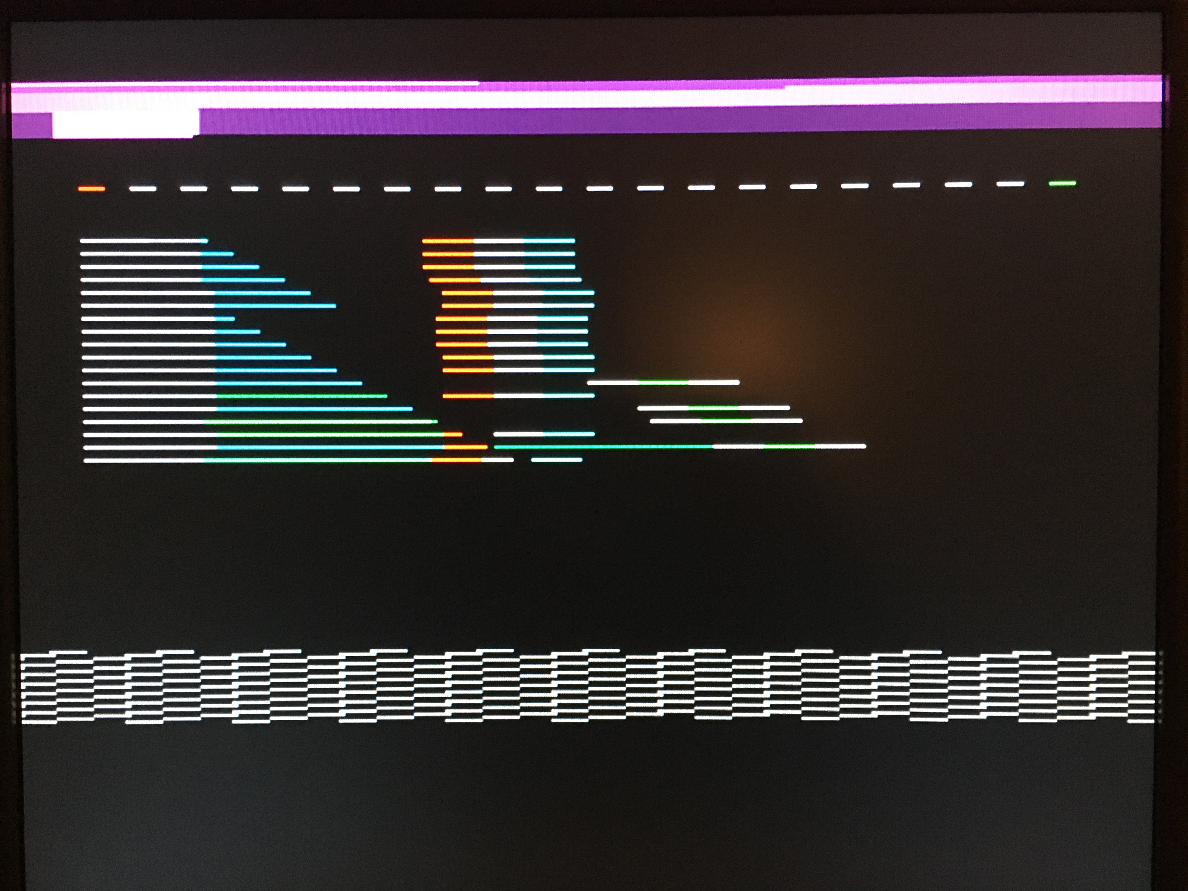
This is what I see on the real machine:
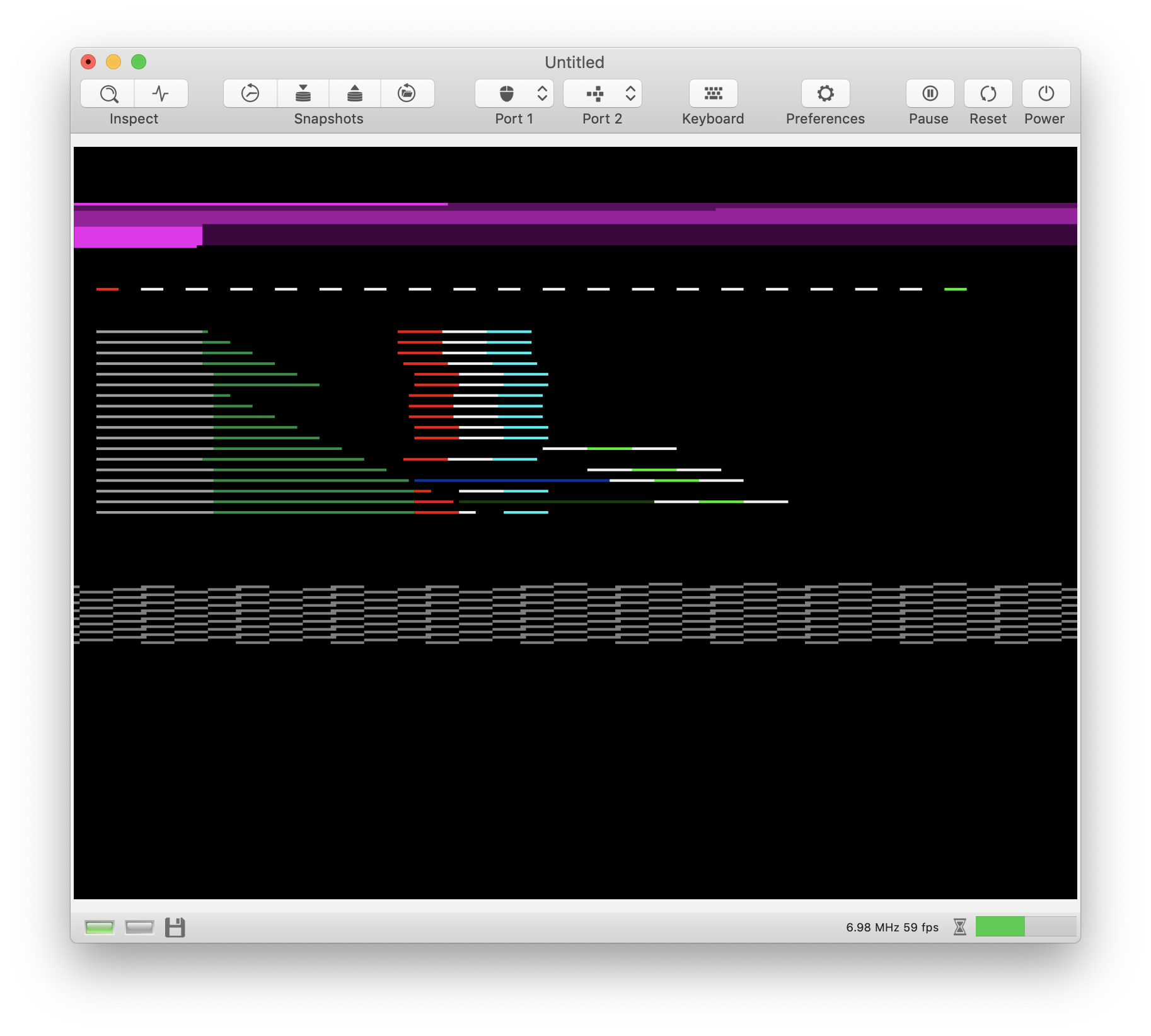
In vAmiga, I can replicate the UAE image when I do the following:
- Change INTENA / INTREQ without any delay.
- Wait for 2 DMA cycles until a changed INTENA or INTREQ value takes effect on the IPL pins of the CPU.
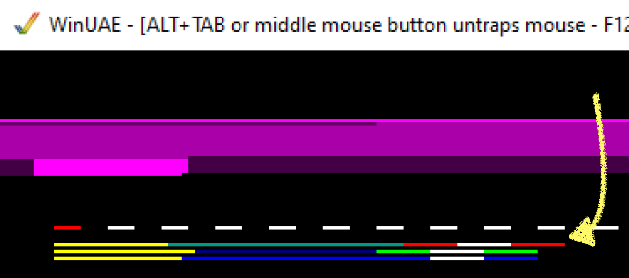
When I bump up the delay from 2 DMA cycles to 4 DMA cycles, vAmiga replaces what my real machine does:
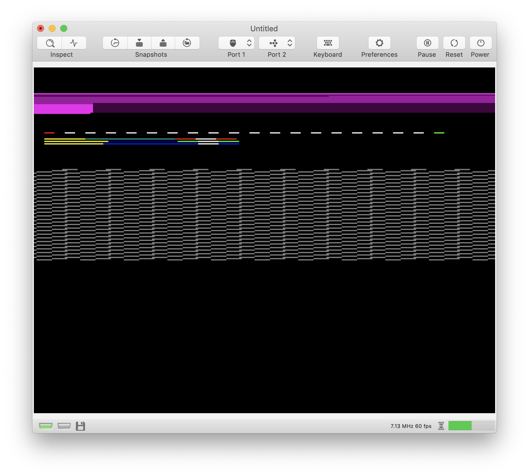
The outcome of this test suggests that the IPL lines have a 4 cycle delay. This is just a hypothesis at the moment. I'll write more test cases to see if it's right or wrong...
 dirkwhoffmann
All 27 comments
I’ve successfully merged one of my old IRQ tests with the new CPU syncing code:
https://github.com/dirkwhoffmann/vAmigaTS/tree/master/Interrupts/int/int2
This is how the latest version of vAmiga performs: 🥳
The image suggests that vAmiga does it right, which is:
- When INTREQ/INTENA is written, change the bits immediately.
- Update the IPL lines of the 68000 with a delay of 4 DMA cycles.
- Poll the IPL lines inside the CPU during the last bus access.
Here is how UAE performs on this test:
(When I change the IPL delay back to a 2 cycle delay, vAmiga looks different to UAE. Hence, UAE must perform interrupt polling in a different way)
It would be awesome to know how the Amiga 1000 (🤤) or Amiga 2000 (🤤) performs on this test.
There is another thing that could be verified on the A1000. If you look at the images closely, you can see that the first red line (drawn by the CPU) and the white reference line (drawn by the Copper) of test case int1 are misaligned on the real machine. In vAmiga, I emulate this behaviour by using different color register delays for the CPU and the Copper.
In the UAE image, it can be seen that no delay difference is used:
It could well be that the pixel shift depends on the Denise or Agnus chip revision. 🤔
dirkwhoffmann
on 27 Jan 2020
Hi Dirk, please do expect two A1000 picture very soon 🤓 ... for int1 and int2
 mithrendal
on 27 Jan 2020
mithrendal
on 27 Jan 2020
I wouldn't make any final conclusions (except that there is something) from these kinds of tests because CPU IPL sampling is microcode based and depends on used instruction. This is the last unknown part in 68000. (or "unknown" because microcode is dumped and logic is known, I just haven't bothered to find out how it actually works)
 tonioni
on 27 Jan 2020
tonioni
on 27 Jan 2020
Senior Captain A1000 is speaking
int1
int2
have a nice journey ...
Roger and over ... 👨🏼✈️
mithrendal
on 27 Jan 2020
I wouldn't make any final conclusions
Definitely, it's just a hypothesis at the moment. There are too many unknowns to make a reliable statement.
(1) When INTREQ/INTENA is written, change the bits immediately.
(2) Update the IPL lines of the 68000 with a delay of 4 DMA cycles.
(3) Poll the IPL lines inside the CPU during the last bus access.
Out of these three conjectures, I am pretty confident that (1) and (2) are true. (3) can only be taken as a rule of thumb that might apply to most commands, but not all.
I think (1) is pretty much backed up by a test that is located here:
https://github.com/dirkwhoffmann/vAmigaTS/tree/master/Interrupts/intreg
To increase confidence in (2), I have created two modification of my original test case (I did change the CPU delay loop so that the IRQ hits different instructions). Both tests run fine with the rules mentioned above (at least I was not able to spot a difference):
Test int3:
Test int4:
Need to stop here... Mithrendal's images are coming up 🤤
dirkwhoffmann
on 27 Jan 2020
Senior Captain A1000 is speaking
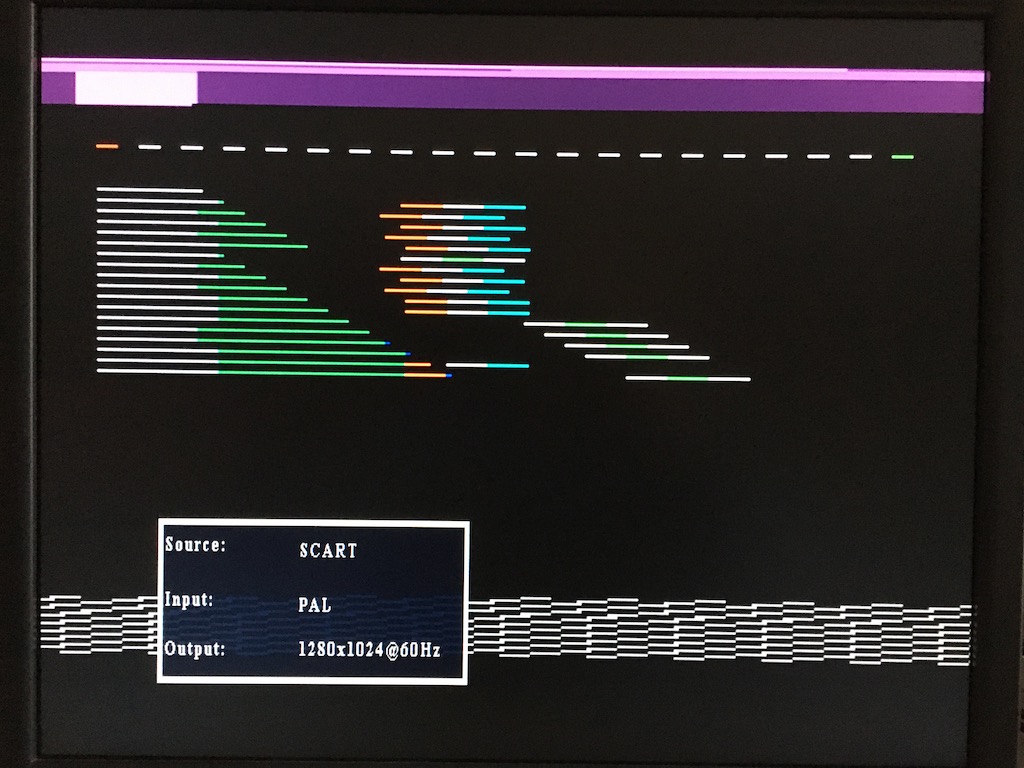
Aye, aye, sir. Images have been uploaded to the repo 👍. The A1000 seems to match the A500 pixel by pixel. The delay discrepancy between Copper writes and CPU writes is also there:

I guess the color change to grey happens because you didn't connect the A1000 to a monitor with proper RGB input (you were mentioning such a thing a couple of month ago). You should really get one of these:
https://www.amazon.de/dp/B078WMDMXN/ref=dp_prsubs_3
Picture quality is pretty good and they are just about 30 EUR.
dirkwhoffmann
on 27 Jan 2020
Yes, Monitor accepts only A1000 composite output. It does not like A1000s RGB signal. Therefore the colors are fading quite a bit.
When colored lines ending in black space. I can clearly detect that red lines tend to fade to grey, green to white, blue to dark grey.
Although my setup suffers from the effect of 🤭composite-output-event-horizon, you can nevertheless very safely rule out that UAE tries to emulate an A1000 in this case.
👨🏼✈️Houston space control we got a severe problem with the composite video signal ....
_Amiga 1000, this is Houston. Predicted cut-off at 11 plus 42. Over. ... Both spacecraft A500/A1000 are looking good. Color fading problem analysed. Over. 00 00 13 35 CDR Roger. ...Color problems due to black holes ... black holes are regions of extremely high density that warp space around them to such an extent that it traps matter and light. If any object goes too close and enters the black hole's point of no return, called the event horizon, it cannot escape the black hole. Even light cannot move fast enough to escape a black hole's pull if it falls beyond this point. https://www.space.com/incredible-black-hole-visualization.html_
Thanks for the hint about the anti-gravity-drive-adapter... 👍🏻
mithrendal
on 27 Jan 2020
I can do some logic analyzer checks later this week to find out IPL line change delay after write to INTENA/INTREQ. I am quite sure I did test these long long time ago but I don't remember results anymore..
- INTENA=
. INTREQ=0, copper and cpu write same value to INTREQ . Check IPL delay. - Same as above but swap INTREQ and INTENA. Check if IPL delay is same.
- IPL already > 0 (INTENA and INTREQ non-zero). Clear interrupt by clearing INTENA. Check IPL delay. Same with clearing INTREQ. Check IPL delay.
CPU SR interrupt mask will be set high enough to not cause any interrupts because it would mess up CPU write tests.
I think these should test all needed combinations. I am not going to do any "when CPU starts processing it" because it depends only on which instruction is currently executing. Note also that before actual interrupt exception starts (stack frame writes), CPU executes some internal operations that take 6 cycles. Most other exceptions need 4 cycles.
btw, there should not be any difference between A1000 and other hardware. Make sure test program isn't getting confused by A1000 Agnus bug. A1000 Agnus generates vertical sync strobe 1 scan line too late (=vertical blank interrupt is also delayed 1 scan line).
tonioni
on 28 Jan 2020
I can do some logic analyzer checks later this week
Awesome 🤤
there should not be any difference between A1000 and other hardware.
Yes, Mithrendals A1000 images match my A500 images pixel by pixel. I wanted to see how the A1000 behaves because my A500 images exhibit a color change shift that depend on whether the Copper or the CPU has written to the register. When the CPU writes to a register, the color change appears two lores pixels earlier. In the comparison images, I’ve noticed that UAE doesn’t seem to emulate this a delay and I therefore thought that it might depend on the chip revision.
A1000 Agnus generates vertical sync strobe 1 scan line too late (=vertical blank interrupt is also delayed 1 scan line).
That’s good to know, because this will be the next thing to debug in vAmiga. My emulator definitely has an issue here (besides many others).
dirkwhoffmann
on 28 Jan 2020
INTENA already set, set INTREQ, clear INTREQ using copper

INTREQ already set, set INTENA, clear INTENA using copper

-> change is practically instant. There is some glitches when it changes (active -> inactive glitch when zoomed shows multiple 7->4->7->4->7 changes). I am not yet sure how CPU samples IPL lines, does it simply do single sample or does it also filter glitches someway.
(Ignore first row in INTREQ trace, it is RGA status with one bit stuck. Not sure where the problem is)
tonioni
on 29 Jan 2020
change is practically instant.
Interesting. So it seems that the CPU has some logic inside that polls the IPL pins in a smart way. Makes sense, because I guess the CPU allows external hardware to change the IPL lines asynchronously to the CPU clock. Unfortunately, this als means that we have no 100% reliable way to determine the exact delay.
dirkwhoffmann
on 29 Jan 2020
Yes, I already said CPU is the problem :)
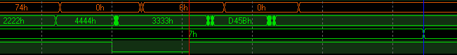
Vertical blank timing. (68h is actually 38h = vertical strobe). Has 2 cycle delay.

Blitter interrupt: has also 2 cycle delay. (I forgot to add probe to Agnus blitter interrupt output, later.. 4h and 6h = CPU reading $dff006 from fast RAM)

tonioni
on 29 Jan 2020
Vertical blank timing. (68h is actually 38h = vertical strobe). Has 2 cycle delay.
Ah, OK, I was confused at first. I've just seen that the physical IPL pins use negative logic (7h is interrupt level 0). This means: The change to value 68h in the first line marks the vertical strobe (vpos/hpos = 0/0 on Amiga 500, vpos/hpos = 1/0 on A1000 ??). Then it takes two cycles until the VERTB bit in INTREQ is set (which changes the IPL lines on the CPU nearly at the same time to 4h which is interrupt level 3). Then the CPU does whatever it does internally to poll the IRQ level. Did I get it right?
dirkwhoffmann
on 29 Jan 2020
Yes. And finally CPU still "waits" at least has 6 cycles (3 DMA cycles, I counted DMA cycles above) added after it detects it before anything visible happens.
Added better blitter interrupt trace, with Paula INT3 pin added. Either 3 or 4 DMA cycle delay here (Depending on if Paula expects high to low or low to high transition). INT2 and INT6 to go which probably have same delays.
Last line is INT3 pin signal state. Agnus only pulses it, length = 1 DMA cycle. (Note another undocumented feature: blitter signals interrupt when last internal operation is done (blitter finished bit is also set at this point), it still needs two more cycles before pipeline is flushed and last D-write is complete)
tonioni
on 29 Jan 2020
And INT2. This confirms Paula either is high to low edge sensitive or level sensitive because CIA INT2 stays active until CIASDR is cleared but IPL changes after 4 DMA cycle delay (red to blue line = 4 DMA cycles). 4 DMA cycle delay matches INT3 delay if counted from high to low transition.
4 cycle delay is unexpectedly long. INT3 has 1 cycle period pulse so Paula obviously does not need 4 cycles to detect it (or blitter interrupt would not work). Which means delay must have some other reason than glitch filtering.
tonioni
on 29 Jan 2020
Logic analyzers seem to be nice toys 🤤. I’ve seen on Amazon that they are not that expensive. A 200M@16CH from Kingst is around 100 EUR. But their software seems to be quite limited. I've downloaded the Kingst demo software, but didn’t find a way to combine channels to get a hex output similar to the one in your images. The professional analyzers are quite costly though.
dirkwhoffmann
on 30 Jan 2020
I have Intronix LA1034 (bought over 10 years ago, there probably are better ones today). 32 channels is absolute minimum if you want to trace 16-bit data bus and other complex signals at the same time. It is still not enough for CPU address bus (which fortunately isn't that useful).
tonioni
on 30 Jan 2020
The A1000 uses 5V logic. I don't know about the other Amiga computers.
So, check that the logic analyzer supports that voltage level.
I got one for snooping some stuff on the Amiga but it was only 3.3V compatible.
On Jan 30, 2020 3:17 AM, Toni Wilen notifications@github.com wrote:
I have Intronix LA1034 (bought over 10 years ago, there probably are better ones today). 32 channels is absolute minimum if you want to trace 16-bit data bus and other complex signals at the same time. It is still not enough for CPU address bus (which fortunately isn't that useful).
—
You are receiving this because you are subscribed to this thread.
Reply to this email directly, view it on GitHubhttps://nam05.safelinks.protection.outlook.com/?url=https%3A%2F%2Fgithub.com%2Fdirkwhoffmann%2FvAmiga%2Fissues%2F274%3Femail_source%3Dnotifications%26email_token%3DAK6SQZGL26NXV42LQF62LELRAKZN5A5CNFSM4KLX5RVKYY3PNVWWK3TUL52HS4DFVREXG43VMVBW63LNMVXHJKTDN5WW2ZLOORPWSZGOEKKUBOQ%23issuecomment-580206778&data=02%7C01%7C%7C9bd7b08f78474555e16608d7a5760b35%7C84df9e7fe9f640afb435aaaaaaaaaaaa%7C1%7C0%7C637159798732193842&sdata=94KitmTiX8lWQPmZV25J2CjJTj7t3Hr0J92DfqJNvBE%3D&reserved=0, or unsubscribehttps://nam05.safelinks.protection.outlook.com/?url=https%3A%2F%2Fgithub.com%2Fnotifications%2Funsubscribe-auth%2FAK6SQZGC4LY3J5C32C75ISTRAKZN5ANCNFSM4KLX5RVA&data=02%7C01%7C%7C9bd7b08f78474555e16608d7a5760b35%7C84df9e7fe9f640afb435aaaaaaaaaaaa%7C1%7C0%7C637159798732213833&sdata=6pphPJQP9ZRMHeBM%2BNAxHwyQYKO6jjNRvV28Qes95EU%3D&reserved=0.
 HarjitSi
on 30 Jan 2020
HarjitSi
on 30 Jan 2020
All Amigas use 5v logic. LA1034 has quite large input voltage range but it has quite small memory which means you can only have about 1 scanline worth of data (with good enough accuracy). Which fortunately is usually more than enough.
I did one more test: polled INTREQR when IPL is going to change due to blitter interrupt. INTREQR reads blitter interrupt bit set max 1/2 cycle earlier before IPL line changes which most likely means delay is some INT2/3/6 line input circuitry feature, not internal Paula interrupt controller feature.
tonioni
on 30 Jan 2020
I tried to get a logic analyzer on eBay today, but my bid was not high enough 🤨.
On the positive side, I've found something interesting today, while debugging issue 221. There is a discrepancy between the real machine and UAE with DDFSTRT/STOP combination $38/$D2. This combination makes (the intro demo of) Exolon to run in UAE, but fail on the real machine. I've written down the details here: https://github.com/dirkwhoffmann/vAmiga/issues/221
This doesn't mean that it's a bug in UAE. It might also be a "feature" of certain Agnus revisions...
dirkwhoffmann
on 1 Feb 2020
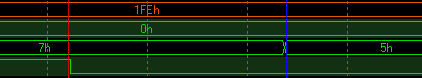
One more interrupt test. First activate INT3 line (blitter), then after 2 DMA cycles activate INT6 (CIAB).
Result: no change to 4 cycle delay before IPL changes. So each Paula interrupt input has separate delay. It also looks IPL signal change is not instant if IPL bits needs both setting and clearing. (7->4 has no glitch but 4->1 has half a cycle zero state)

(red = INT3 activates, yellow = INT6 activates, blue = 0->3 IPL, pink = 3->6 IPL)
tonioni
on 2 Feb 2020
I’m a little bit confused now. From the discussion above, I concluded that the IPL lines change nearly instantly and the delay is caused inside the CPU. The last waveform looks like we have some kind of delay pipeline inside Paula that causes a 3 or 4 cycle delay. Something like this 🤔:
Level derived from INTENA / INTREQ: 0001234566666...
                               IPL: 0000000123456...
Yes. Long time ago I noticed blitter and CIA interrupts have a delay but I never bothered to check them properly and I simply assumed all interrupts have identical delay. (There is at least one demo that needs this delay or its blitter interrupt handling will corrupt the display..)
But it seems only interrupts that are external to Paula (INT2, 3 and 6) have longer delay. I still need to check if audio/disk/etc also have delay but testing it isn't that simple.
There is still CPU introduced delay but it is same for all interrupts.
tonioni
on 4 Feb 2020
There is at least one demo that needs this delay
Do you remember the name of this demo?
dirkwhoffmann
on 6 Feb 2020
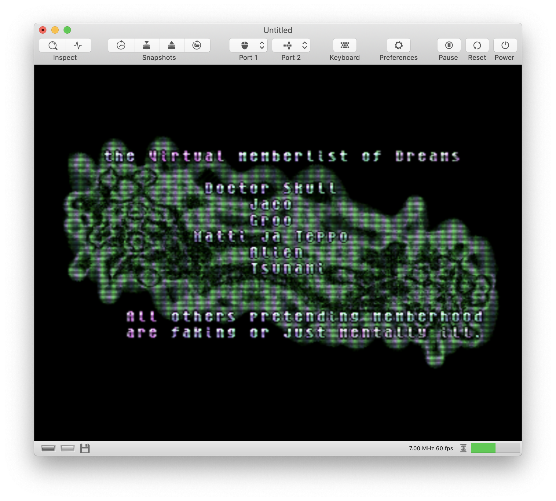
Absolute Inebriation / Virtual Dreams, full screen 2 transparent vector cubes -part, after planet explodes. There is at least single frame glitch (If I remember correctly) somewhere mid screen if something goes wrong. (btw, there are few single frame tiny glitches in other parts that also happens on real hardware, above glitch does not).
tonioni
on 6 Feb 2020
full screen 2 transparent vector cubes -part
I guess it's this part then... right after the planet exploded.
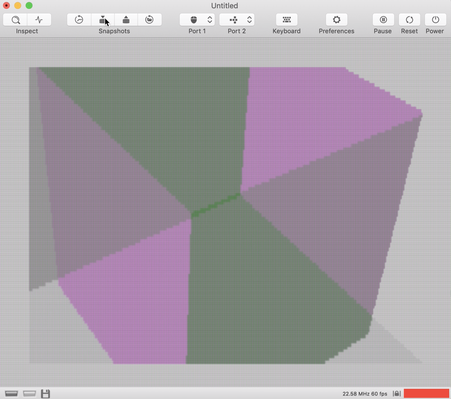
I didn't spot anything wrong in vAmiga, but there are other graphics glitches that are definitely due to emulator bugs. Nevertheless, it's one of the coolest demos I've seen so far...
dirkwhoffmann
on 9 Feb 2020
I rewrote UAE to only delay external interrupts (and do CPU IPL detection delay) and above part (2xcubes) still does work fine but will have glitches if delay is too small.
If you want some other interrupt timing related test cases: IK+ (no sound effects), Warhead (bad title music, bad sound effects.), pack disk Gleat Stuff #1 / Black Robes (vector object filling leaks).
I have lots of test statefiles, what about supporting *.uss files? :)
tonioni
on 14 Feb 2020
Related issues
dirkwhoffmann
·
3Comments
dirkwhoffmann
·
3Comments
 KenDFish
·
3Comments
dirkwhoffmann
·
4Comments
dirkwhoffmann
·
3Comments
KenDFish
·
3Comments
dirkwhoffmann
·
4Comments
dirkwhoffmann
·
3Comments
Most helpful comment
Yes. And finally CPU still "waits" at least has 6 cycles (3 DMA cycles, I counted DMA cycles above) added after it detects it before anything visible happens.
Added better blitter interrupt trace, with Paula INT3 pin added. Either 3 or 4 DMA cycle delay here (Depending on if Paula expects high to low or low to high transition). INT2 and INT6 to go which probably have same delays.
Last line is INT3 pin signal state. Agnus only pulses it, length = 1 DMA cycle. (Note another undocumented feature: blitter signals interrupt when last internal operation is done (blitter finished bit is also set at this point), it still needs two more cycles before pipeline is flushed and last D-write is complete)