Tasmota: Wofea WiFi Switch Smart Garage Door Opener support (Tuya)
I bought some smart garage door openers at AE: https://aliexpress.com/item/32997953761.html

After opening it, I saw that it is a tuya device based on a TYWE2S module and a STM8S0003F3 mcu.
Off course I flashed it with latest tasmota firmware and begun investigations.

MCU obviously controls 3 tuya ID's (DpID).
When pressing the button on the device, the relay switches for 2 secs (close contact for garage door controller). Here the log:
00:00:18 TYA: RX Packet: "55aa03070005010100010011"
00:00:18 TYA: RX Device-1 --> MCU State: Off Current State:On
00:00:18 SRC: Switch
00:00:18 RSL: stat/GarageRechts/RESULT = {"POWER":"OFF"}
00:00:18 RSL: stat/GarageRechts/POWER = OFF
00:00:19 CFG: Saved to flash at F4, Count 394, Bytes 4096
00:00:20 TYA: RX Packet: "55aa03070005010100010112"
00:00:20 TYA: RX Device-1 --> MCU State: On Current State:Off
00:00:20 SRC: Switch
00:00:20 RSL: stat/GarageRechts/RESULT = {"POWER":"ON"}
00:00:20 RSL: stat/GarageRechts/POWER = ON
So obviously switch hast DpID 1 and can be controlled already with actual software.
Closing the "door is closed" contact at runtime 01:01:34 (in fact it is a magnetic switch on a long cable) gives following output:
00:01:34 TYA: RX Packet: "55aa03070005650100010075"
00:01:34 TYA: RX Device-101 --> MCU State: Off Current State:Off
00:01:34 TYA: RX Packet: "55aa03070005010100010011"
00:01:34 TYA: RX Device-1 --> MCU State: Off Current State:On
00:01:34 SRC: Switch
00:01:34 RSL: stat/GarageRechts/RESULT = {"POWER":"OFF"}
00:01:34 RSL: stat/GarageRechts/POWER = OFF
00:01:34 CFG: Saved to flash at FA, Count 396, Bytes 4096
00:01:34 TYA: Send "55aa00000000ff"
00:01:34 TYA: RX Packet: "55aa030000010104"
00:01:34 TYA: Heartbeat
00:01:50 TYA: RX Packet: "55aa03070005650100010176"
00:01:50 TYA: RX Device-101 --> MCU State: On Current State:Off
00:01:50 SRC: Switch
00:01:50 RSL: stat/GarageRechts/RESULT = {"POWER":"ON"}
00:01:50 RSL: stat/GarageRechts/POWER = ON
00:01:50 TYA: RX Packet: "55aa03070005010100010112"
00:01:50 TYA: RX Device-1 --> MCU State: On Current State:On
00:01:50 TYA: Send "55aa00000000ff"
00:01:50 TYA: RX Packet: "55aa030000010104"
00:01:50 TYA: Heartbeat
00:01:50 CFG: Saved to flash at F9, Count 397, Bytes 4096
At 00:01:50 I removed the magnet and switch was reset.
So this switch seems to have DpID 101 (hex 0x65) and cannot be controlled neither queried by actual software. I do not have the option to set a switch's ID to 101.
When I query the device initialization status 55 aa 00 08 00 00 07 a device with ID 7 responds as well. Dunno what it is for, could imagine that it is some kind of LED status.
00:04:40 CMD: SerialSend5 55 aa 00 08 00 00 07
00:04:40 RSL: stat/GarageRechts/RESULT = {"SerialSend":"Done"}
00:04:40 TYA: RX Packet: "55aa03070005010100010112"
00:04:40 TYA: RX Device-1 --> MCU State: On Current State:On
00:04:40 TYA: RX Packet: "55aa0307000807020004000000001e"
00:04:40 TYA: RX Unknown ID=7
00:04:40 TYA: RX Packet: "55aa03070005650100010176"
00:04:40 TYA: RX Device-101 --> MCU State: On Current State:Off
So my desire is the possibility to configure ID's for the tuya switch(es), just like SetOption 44 for the PowerID - then I could integrate this devices to my home control (OH2).
 riogrande75
All 27 comments
@shantur Tuya;-) Can you take a look?
 Jason2866
on 30 Aug 2019
Jason2866
on 30 Aug 2019
This was discussed in Discord chat.
Currently this isn't supported. It needs to be implemented
 shantur
on 31 Aug 2019
shantur
on 31 Aug 2019
Closing this issue as it has been answered.
Support Information (Guide)
See Wiki for more information.
See FAQ for common questions/answers and links if none of your question is in the list.
See Chat for more user experience.
See Community for forum.
See Code of Conduct
 ascillato2
on 1 Sep 2019
ascillato2
on 1 Sep 2019
I am working on a configurable implementation for Tuya mcu devices.
Please re-open this to track the requirement.
shantur
on 2 Sep 2019
Reopened as requested. Thanks.
ascillato2
on 2 Sep 2019
Fixed in #6353
shantur
on 4 Sep 2019
For the record, I managed to flash this over the air with the kueblc tuya convert fork (you need to switch to the new-api branch).
@riogrande75 whats settings are you using in the Configure Module and Configure Template of the device's config?
 juanjux
on 27 Sep 2019
juanjux
on 27 Sep 2019
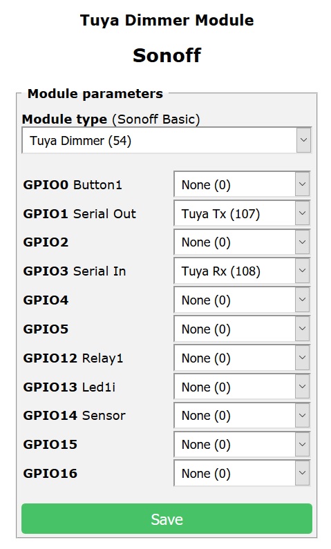
TuyaMCU (54). No Template, I used this settings to get stuff on my MQTT:
TuyaMcu 41,1
TuyaMcu 2,101
SwitchTopic 0
Rule1 on switch2#state do publish stat/GarageLinks/sensor %value% endon
Rule1 on
Switchmode2 2
riogrande75
on 27 Sep 2019
Thank you @riogrande75, this worked for me except every couple seconds it would lower the dimmer value until it went to 0 and the switch turned on, starting again from 100. Curiously I was able to solve it using the fade on console command, which very WTFishly stopped the fading.
PS: for the record, the fading problem was definitely solved using the command SetOption65 1, which disables it as a dimmer.
juanjux
on 27 Sep 2019
@riogrande75 and @juanjux
Am trying to get the Wofea Smart Garage Controller to work with Tasmota but with no luck.
The sensor doesn't seem to work and as soon as I toggle the button (on to off) it will return to on within seconds. Disconnection the magnetic door sensor will trigger the led light on the controller (it will start flashing red/blue fast) but this does nothing in Tasmota.
Could you please provide me with your settings so I can copy them to my controller?
I have tried the following steps:
- Module type: TuyaMCA (54)
- No Template set
- MQTT and Domoticz settings are correct (Domoticz only IDX 1 set to 49 which is the correct number and works from Domoticz)
- In console I entered the following commands, one after each other (and also tried all together in one time).
TuyaMcu 41,1
TuyaMcu 2,101
SwitchTopic 0
Rule1 on switch2#state do publish stat/GarageLinks/sensor %value% endon
Rule1 on
Switchmode2 2
SetOption65 1
fade on (this gives a result 'Command unknown').
Note: the controller is not yet connected to the garage doorcontroller (Chamberlain LM60) which is located in my garage. So the black and red wires are not connected to anything. Could this be the problem? I tried to find out what would happen if I connect them as soon as I toggle the button, but connecting them doesn't make the switching between on-off go away.
 JHurk
on 21 Nov 2019
JHurk
on 21 Nov 2019
Update: I managed to get the Wofea Garage Door Controller working, at least half of it functions are working; opening and closing.
The problem is with the reed (magnetic sensor). It is connected at the moment so the command in console is always the same:
4:50:50 MQT: tele/sonoff/RESULT = {"TuyaMcuReceived":"55AA030000010104"}
I do not have anywhere I can see the reed-status (connected or disconnected) and would not know how to get this to work. As soon as I disconnect the reed after I push the button and the door opens (the reed would then disconnect if it would be attached to the door, so I simulate this by disconnecting it manually) the door stops after a few seconds and after a few seconds the door closes. This continues until I connect the reed again.
How can I separate the reed and door button? I only want the reed to give me the door status (open/closed; disconnected/connected) and only want the button to act as a opener.
JHurk
on 23 Nov 2019
@shantur ⬆️
 meingraham
on 23 Nov 2019
meingraham
on 23 Nov 2019
@JHurk
This is what I use.
SwitchMode":[4,1,0,0,0,0,0,0]
{"Rule1":"Open","Once":"Open","StopOnError":"Open","Free":382,"Rules":"on switch2#state=1 do publish2 stat/SW_Garage/POWER2 Open endon on switch2#state=0 do publish2 stat/SW_Garage/POWER2 Closed endon"}
TYA: fnId=11 is set for dpId=1
TYA: fnId=2 is set for dpId=101
I have the LED off, but it could be ledlink.
I have interlock 1
I also have switch debounce, you shouldn't need this. I use a different reed switch, but I mounted it the wrong way. so I triggers twice as it slides open.
in HA switch config I have
````
switch:
tasmota setup, module 54, switchmode1 4, switchmode2 1, switchdebounce 1000(stops reed switch flicker), interlock 1
# rule1 on switch2#state=1 do publish2 stat/SW_Garage/POWER2 Open endon on switch2#state=0 do publish2 stat/SW_Garage/POWER2 Closed endon
# publish2 in tasmota is rule to publish retained msg
- platform: mqtt
name: "Garage Door"
state_topic: "stat/SW_Garage/POWER2"
command_topic: "cmnd/SW_Garage/POWER1"
availability_topic: "tele/SW_Garage/LWT"
qos: 1
state_on: "Open"
state_off: "Closed"
payload_on: "1"
payload_off: "0"
payload_available: "Online"
payload_not_available: "Offline"
retain: false
````
this is the card I use.
````
entity: switch.garage_door
icon: 'mdi:garage'
lock:
enabled: true
unlock: tap
show_state: false
state:
- color: 'rgb(255, 0, 0)'
icon: 'mdi:garage-open'
name: Garage Open
styles:
card:
- animation: blink 2s linear infinite
value: 'on' - color: 'rgb(0, 205, 0)'
icon: 'mdi:garage'
name: Garage Closed
value: 'off' - color: 'rgb(255, 0, 0)'
icon: 'mdi:garage-alert'
name: Garage Offline
spin: true
value: unavailable
tap_action:
action: call-service
service: switch.turn_on
service_data:
entity_id: switch.garage_door
type: 'custom:button-card'
````
 HABuild
on 25 Nov 2019
HABuild
on 25 Nov 2019
Thanks, I have mapped the following components and dpId
{"TuyaMCU":[{"fnId":11,"dpId":1},{"fnId":2,"dpId":101},{"fnId":1,"dpId":111}]}
And set the rule as suggested:
on switch2#state=1 do publish2 stat/SW_Garage/POWER2 Open endon on switch2#state=0 do publish2 stat/SW_Garage/POWER2 Closed endon
I use Domoticz so only the first half of you post is relevant for me. But hopefully it works, will report back asap.
JHurk
on 25 Nov 2019
Unfortunately nothing changed with these new settings:
I can still open/close the door with a command from the WebUI, but as soon as the magnetic reeds separates I can not give any command from the WebUI and the door will not close. Only when I connect the reed again I can give a command to close/open the door.
TuyaMCU":[{"fnId":11,"dpId":1},{"fnId":2,"dpId":101},{"fnId":1,"dpId":111}]
Rule1":"ON","Once":"ON","StopOnError":"ON","Free":382,"Rules":"on switch2#state=1 do publish2 stat/SW_Garage/POWER2 Open endon on switch2#state=0 do publish2 stat/SW_Garage/POWER2 Closed endon
JHurk
on 25 Nov 2019
The reed will invert the reported state without actually changing the power to wofea relay.
It took some effort but this is what I did to get it working with Domoticz.
DO NOT, I repeat do not, use the Tasmota Domoticz settings! The mismatch between what is reported and what is really happening seems to confuse Domoticz too much.
Tasmota 6.7.1, MQTT 3.1.1
_The Wofea_
- TuyaMcu 11,1
- TuyaMcu 2,101
- SwitchTopic 0
- // feedback of relay to Domoticz virtual device with idx '229' and type 'Switch'
Rule1 on Power1#State do publish domoticz/in {"idx":229,"nvalue":%value%,"svalue":"","Battery":100,"RSSI":8} endon
Rule1 on - SetOption65 1
- MQTT configuration, I changed the topic to 'garagedeur'
This will cause the Wofea to report changes to Domoticz via MQTT. Notice the bold idx numbers, change these into your idx values.
_Domoticz_
This is not a pretty solution but works well. This is for Domoticz on Windows. When you are running Domoticz on Linux life is easier as you can use the paho mqtt lib directly from a python script associated with On Action and Off Action of the virtual switch.
- Create the virtual device of type Switch and note the idx value it is assigned
- Use the idx value on the Wofea, see above
- Install a command line MQTT client. I used HiveMQ MQTT CLI, you also need to install the Java runtime (jre) to make this run. Extract mqtt-cli.exe into c:\Program Files (x86)\Domoticz
- Create an old fashioned batch file in c:\Program Files (x86)\Domoticz\scripts with the name wofea.bat" and the following content:
.\mqtt-cli.exe pub -t cmnd/garagedeur/power1 -m toggle -h mqtt-host -V 3
change **mqtt-host to the name or ip address of your MQTT broker - In the domoticz UI go to the Switches tab and Click 'Edit' on the virtual switch you created. There should be input fields for 'On Action' and 'Off Action". You must use short (8.1) names here. I entered:
script://c:\progra~2\Domoticz\scripts\wofea.bat
in both of the fields. Then click 'Save to return to the switches tab.
Clicking on the switch in the UI will now send a toggle command to the Wofea via MQTT.
_The Result_
- With the door closed, the switch displays off.
- Click the switch, with a small delay the switch displays on and 2 seconds later off again, a few seconds after that the switch displays on again as the reed loses contact.
- Now the door is open and the switch displays on.
- Click the switch, with a small delay the switch displays off and 2 seconds later on again, after a longer period the switch displays off again as the reed makes contact
Sorry for the lengthy post, but it took some searching and tweaking to get it "just right".
 Red-F
on 30 Nov 2019
Red-F
on 30 Nov 2019
_Domoticz_
This is not a pretty solution but works well. This is for Domoticz on Windows. When you are running Domoticz on Linux life is easier as you can use the paho mqtt lib directly from a python script associated with On Action and Off Action of the virtual switch.
- Create the virtual device of type Switch and note the idx value it is assigned
- Use the idx value on the Wofea, see above
- Install a command line MQTT client. I used HiveMQ MQTT CLI, you also need to install the Java runtime (jre) to make this run. Extract mqtt-cli.exe into c:\Program Files (x86)\Domoticz
- Create an old fashioned batch file in c:\Program Files (x86)\Domoticz\scripts with the name wofea.bat" and the following content:
.\mqtt-cli.exe pub -t cmnd/garagedeur/power1 -m toggle -h mqtt-host -V 3
change **mqtt-host to the name or ip address of your MQTT broker- In the domoticz UI go to the Switches tab and Click 'Edit' on the virtual switch you created. There should be input fields for 'On Action' and 'Off Action". You must use short (8.1) names here. I entered:
script://c:\progra~2\Domoticz\scripts\wofea.bat
in both of the fields. Then click 'Save to return to the switches tab.Clicking on the switch in the UI will now send a toggle command to the Wofea via MQTT.
@Red-F
Thanks for the great explanation and your help.
The second part (see quote) is not clear. I am running Domoticz and Mosquitto (MQTT) on a Synology.
Hopefully you are abel to provide me with the steps needed when running these on a Synology?
I can make a script but should the content be the same? And I can add the script in the 'On Action' and 'Off Action' field of the switch. But is this enough?
Thanks!
JHurk
on 1 Dec 2019
I too got this to work for a Wofea garage door opener (model wg-088). The relay worked out of the box (dpid 1 is mapped to fnid 11 by default) but for the status (reed sensor) I had to map dpid 101 to fnid 2 and then had to map values 00, 01 to closed,open for it to work. The issue I am struggling with is the Wofea garage door opener relay works as a momentary button to resemble the action of someone pressing the wall button and will actuate for about 2 seconds when activated then go back to off. I would like to change this so that it stays activated longer then this 2 seconds because my garage door sometimes requires a longer press of the button for it to actually continue to close. Is it possible to change this or is this embedded in the hardware of this device?
 mondjef
on 15 Sep 2020
mondjef
on 15 Sep 2020
This is my first time serial flashing so im sure im doing something wrong here. I hope someone can correct me.
Its the same model and i tried reversing rx/tx connections as well. I tried mains power as well and it didn't work.
I tried tasmotizer and esptool and both produce same error "Failed to connect, Timed out waiting for packet header."
The rx/tx leds light up on the flasher so im assuming its something with the grounding/entering into flash mode. I hold the button as i plug it in and nothing happens.

 AliMickey
on 30 Oct 2020
AliMickey
on 30 Oct 2020
I see fine copper wires that could create shorts and make it fail. If not now then most probably later. Cut them away.
Dont try with mains. Connect 2 new 1.5V batteries or a near empty lithium battery (full it has 4.2 V which is too much, measure it) if you think power from the serial adapter is too weak.
I dont know this device. What you do to enter flash mode is usually correct, but some devices use other methods.
Thats all I have. Maybe try discord chat. It helped me more than once.
 joba-1
on 30 Oct 2020
joba-1
on 30 Oct 2020
I see fine copper wires that could create shorts and make it fail. If not now then most probably later. Cut them away.
Dont try with mains. Connect 2 new 1.5V batteries or a near empty lithium battery (full it has 4.2 V which is too much, measure it) if you think power from the serial adapter is too weak.
I dont know this device. What you do to enter flash mode is usually correct, but some devices use other methods.
Thats all I have. Maybe try discord chat. It helped me more than once.
oh the photo is bad, i had a cleaner cables before. but i will try resoldering them all better.
power seems fine though since it starts up and enters pairing mode/ap mode.
i wonder if they locked it down so it cant enter flashing mode? is that a possibility?
EDIT: successfully flashed by holding a wire from IOO to Gnd on the daughter board for the duration of the flash.
AliMickey
on 30 Oct 2020
to flash my device I just used tuya convert and did it over the air without issue
mondjef
on 30 Oct 2020
the one issue I am still trying to figure out is there are messages as the following being sent from the device that I am not sure what they mean exactly yet....this is produced in the log of Openhab for this device.
2020-10-29 19:32:56.933 [WARN ] [t.generic.ChannelStateTransformation] - Executing the JSONPATH-transformation failed: Invalid path '$.TuyaReceived.101.DpIdData' in '{"TuyaReceived":{"Data":"55AA0307000807020004000000001E","Cmnd":7,"CmndData":"0702000400000000","DpType2Id7":0,"7":{"DpId":7,"DpIdType":2,"DpIdData":"00000000"}}}'
mondjef
on 30 Oct 2020
I bought the same module but the device I got is now build around the TUYA WR2E module (https://developer.tuya.com/en/docs/iot/device-development/module/wifi-module/wr2e?id=K97scnsjhue4h). This doesn't seem to be based on anymore on ESP82xx.
Tried to flash it but that didn't work.


 mhaket
on 2 Nov 2020
mhaket
on 2 Nov 2020
Just an FYI. This opener still comes with the older TYWE2S module, but it has an updated firmware. This firmware CANNOT be updated by tuya convert, there is an open issue for that.
I have not yet tried soldering and doing a wired firmware conversion.
 SentinelCQ
on 11 Dec 2020
SentinelCQ
on 11 Dec 2020
I can confirm my unit came from Amazon with the newer firmware that was incompatible with tuya convert. I was able to flash with the solder points listed above.
 jacobhopkins117
on 18 Dec 2020
jacobhopkins117
on 18 Dec 2020
Did you need to also do the IOO to GND? If yes, any chance you can post a picture of your setup? this will be my first time doing a solder based flash.
SentinelCQ
on 18 Dec 2020
Related issues
 ximonline
·
3Comments
ximonline
·
3Comments
 TylerDurden23
·
3Comments
TylerDurden23
·
3Comments
 he-so
·
3Comments
he-so
·
3Comments
 Ndrinta
·
3Comments
Ndrinta
·
3Comments
 JoergZ2
·
3Comments
JoergZ2
·
3Comments
Most helpful comment
Fixed in #6353