Is this Wi-Fi Dimmer supported?
I have used tuya-convert to flash Tasmota, and it works. I have it with Tasmota.
I can't find any Info about this device. I have tried Tuya Dimmer but no success (no switching, no dimming control from the Tasmota interface).
Thanks!
 jsponz
All 289 comments
No. Please read and this CONTRIBUTING
 Jason2866
on 2 May 2019
Jason2866
on 2 May 2019
Closing this issue as it has been answered.
Support Information (Guide)
See Wiki for more information.
See Chat for more user experience.
See Community for forum.
See Code of Conduct
 ascillato2
on 2 May 2019
ascillato2
on 2 May 2019
Hello i have have the same device, i flash tasmota 6.5, but what is the pin occupancy for the serial connection and switch ? Have any a idea ?
 dr-apple
on 8 May 2019
dr-apple
on 8 May 2019
I also recently bought this device and I'm very intersted in Tasmota support. It's the cheapest wifi AC dimmer out there (~15$ price point), very interesting!
 keesschollaart81
on 8 May 2019
keesschollaart81
on 8 May 2019
@dr-apple I have tried all the possible options with no success.
I guess there is also anything related to serial communication and/or chip identification.
@keesschollaart81 I am with you. It works ok. Robust and cheap.
Any help is welcome!
jsponz
on 8 May 2019
@jsponz thank you for the info, i have testet all options for the button but zero :-(
I've been looking for hours in the network for schematics, pin assignments, but I can not find anything about the thing or the structure ....
https://docs.tuya.com/en/hardware/WiFi-module/wifi-e1s-module.html
dr-apple
on 8 May 2019
You guys may be stuck between a rock and a hard place.
First let me ask if you have tried different Tuya Dimmer IDs (SetOption34)?
It is likely that the dimming function is not handled by the ESP chip itself. The dimming function is probably handled by a separate MCU. The dimming actions to perform are usually communicated via codes sent from the ESP chip to the MCU via the serial communications interface. The dimming codes vary from device to device, even revision to revision.
In order for Tasmota to work if installed on the dimmer, Tasmota needs to send the right codes when an action request is made to it and also receive codes to confirm the action completed or to know what the device is up to when a change is made physically at the device (i.e., a human made the change). If you know the codes, then these can be programmed into Tasmota rules or customized into the code itself and compiled into the firmware.
But first you have to know the codes. And for that you would have had to reverse engineer the original firmware. Of course, if you provision the device on the Smart Life app in order to see it operate, Smart Life may update the firmware and thus blocking the ability to use Tuya-Convert. And thus the rock and a hard place :grimacing:
If you backed up the original firmware, you may be able to flash it back onto your device to attempt the reverse engineering process. @digiblur went through that is some of his videos.
Regards.
Mike
 meingraham
on 8 May 2019
meingraham
on 8 May 2019
Impressive work from @digiblur 💯, super cool to see these videos.
Some pictures from inside of the device:
https://ibb.co/pPhL3cL
https://ibb.co/7Ysv6gR
https://ibb.co/3pmzzVh
https://ibb.co/s2Gg5S3
https://ibb.co/jLbc7Yg
After flashing Tasmota is was able to configure it via the web interface and I tried some different combinations but without success. Module set to 'Tuya Dimmer (54)'. After trying some different RX/TX configuration and some random guesses for the SetOption34 I was not able to see any RX messages in the console (with web log level 4). Also no incoming data when manually switching the device.
What would be a next thing to try/work out? I don't think I'm able to solder/connect to the serial port myself (too small & no experience).
keesschollaart81
on 8 May 2019
@keesschollaart81 Thanks for your analysis. I spent some time as well. One of my devices is broken: it does not boot.
The other one is flashed with Tasmota, but nothing happens. Same result as you have.
jsponz
on 9 May 2019
if I could find out the pin assignment, then I would try to read the protocol and recreate .... I have to lie on the couch for 2 weeks, have time ;-)
dr-apple
on 9 May 2019
Maybe @jsponz can disassemble his broken device and expose the chip so that we can see which Tuya device it compares with / which pins we have?
keesschollaart81
on 9 May 2019
Which pins did you try for TX/RX?
 digiblur
on 9 May 2019
digiblur
on 9 May 2019
@keesschollaart81 Of course!
It is already disassembled :-)
Tomorrow I will send you pictures.
jsponz
on 9 May 2019
@digiblur same as described here
I also tried to point the Tuya Tx107 and Rx108 to the GPIO1 and 3. Also swapped 107 and 108 in both configs. Every test I tried to toggle the input switch but the logging is always the same
By the way, the bulb seems to be on the lowest brightness after power on. The input switch does not turn on/off the light.
keesschollaart81
on 9 May 2019
@keesschollaart81 the same happens here with the original firmware. I have reported it and they have told me that it is a production issue. A new device is on the way with this fix. I will confirm as soon as I have it...
However, after flashing one unit with Tasmota (as it is right now without support for this device), I see that the light is always off, so I guess it is firmware related.
jsponz
on 10 May 2019
After I set TuyaRx18 to GPIO16 it does not boot any more... :-/
keesschollaart81
on 10 May 2019
You must reset the esp with 3 x ac power on / off with 2 sec sleep, after that, the esp has delete the config make a hotspot....
dr-apple
on 10 May 2019
@dr-apple, @keesschollaart81 the same happened here and esp did not boot up anymore.
I will try later, when taking pictures.
jsponz
on 10 May 2019
Not all GPIOs can be used for all. See https://github.com/arendst/Sonoff-Tasmota/wiki/Expanding-Sonoffs#restrictions
Jason2866
on 11 May 2019
@jsponz any update?
keesschollaart81
on 14 May 2019
@keesschollaart81 Sorry, I have a personal issue. Tomorrow I will take the pictures.
jsponz
on 14 May 2019
As promises, please find attached the pictures.


jsponz
on 15 May 2019
It seems there is a sort of ESP module hooked on a PCB with a MCU.
The type of the MCU cant be identified on the photos. Next step is to identify type of MCU
and someone hast to hook up a logic analyzer and sniff commands that needs to be sended
and are received from the ESP to activate on off and dimming. If this is done and providing this detailed information someone can implement this type of dimmer in Tasmota.
Tbh i dont believe this will happen because there are already supported easy to buy dimmers available.
Jason2866
on 15 May 2019
@Jason2866
Please, can you say me what Types/Models of dimmers for in-wall? (only box without switch or push-button) is supported by tasmota?
5 Days ago I've buyed 4pc of the parts above - shit happens
sorry for my english :-(
 CJS0815
on 17 May 2019
CJS0815
on 17 May 2019
The Model is : QS-WIFI-D01-TRAIC
dr-apple
on 17 May 2019
You mean TRIAC?
Not available in Europe :-(
Not on aliexpress
Do you have a dealer for me?
CJS0815
on 17 May 2019
? show the first post here, it from ali and came frome china ?
dr-apple
on 17 May 2019
??? I dont understand !?!
The part from the first post was actual not supported - or did I read complete wrong?
I asked for a supported module like this from the first post, but even supported ...
CJS0815
on 17 May 2019
There is none.
Jason2866
on 17 May 2019
yes but you have asked :
Not available in Europe :-(
Not on aliexpress
Do you have a dealer for me?
and i have mean, you mean this this device ;-)
dr-apple
on 17 May 2019
No , sorry (I tell you, my english is ....)
What type or models do you mean with "because there are already supported easy to buy dimmers available"?
CJS0815
on 17 May 2019
@CJS0815 from you: sorry (I tell you, my english is ....)
my too ;-) sorry
dr-apple
on 17 May 2019
Is this Wi-Fi Dimmer supported?


The product was dealed with documentation in germany
Is thera a chance to get it together with Tasmota?
CJS0815
on 17 May 2019
Here the new version V5:
https://ex-store.de/2-Kanal-WiFi-WLan-Relay-V5-Blackline-fuer-Unterputzmontage
Is this tasmota ready ? YES
https://github.com/arendst/Sonoff-Tasmota/wiki/EXS-Relay-V3.1-&-V5.1
dr-apple
on 17 May 2019
@keesschollaart81 Any update? :)
jsponz
on 22 May 2019
@dr-apple
Sorry, its not a new version, that is another version - the V5 is only a Switch-Relay
I speak from another product called V4 Dimmer-Modul
The pictures I've send above are from this V4 dimmer-Modul
CJS0815
on 22 May 2019
To be clear @CJS0815 I believe @jsponz and I are talking about the device linked in the opening post with pictures here https://github.com/arendst/Sonoff-Tasmota/issues/5737#issuecomment-490588738 and here https://github.com/arendst/Sonoff-Tasmota/issues/5737#issuecomment-492511979. This: https://github.com/arendst/Sonoff-Tasmota/issues/5737#issuecomment-493426380 is a completely (non dimmer) different device, let's not mess up this thread :-) which is about a very cheap Tuya based 220V AC dimmer.
As said, my first one got bricked. I now have a new one but I have not yet flashed it and I'm not sure I will do that, as long as there is no additional progress.
Looking at the pictures of @jsponz the ESP chip looks quite different from the one @digiblur got to work in his video. I guess unless someone with more experience/tools spends time on it, we have to use it as it comes with Tuya's firmware...
keesschollaart81
on 23 May 2019
@keesschollaart81 thanks for your clear summary.
I had one issue with the first two units. When switching it off, there was a minimum level of light. That happened with the original firmware and hardware. They have kindly sent me two new units and they work as expected. When off, it is off :-)
It is worth to make it work with Tasmota. It is cheap, robust and good quality. It works with LED lamps, incandescents, etc. It shouldn't be so complex, considering that the main effort is made for the other modules.
Sorry but I can't do it. I don't have my debugging tools in my current location...
jsponz
on 23 May 2019
As you might have seen in #5859 I'm also trying to make this dimmer work with Tasmota.
Did try the Tuya convert road but did not manage to make it work. But glad you did, that probably means there is hope.
I will try the convert later then on a fresh installed Ubuntu or something.
Anyway I took one for the team and took mine to pieces, also removing the RF shield.
Did some measurements to find the pinout of this special module:

The MCU on the back is a STM8S003F3:
https://www.st.com/resource/en/datasheet/stm8s003f3.pdf
And TX and RX is connected to the ESP's TX and RX pins.
The same MCU seems to be used in dimmer they are talking about here:
469
But it's hard to tell if the firmware is the same.
Hope this is of help for some...
 MortenVinding
on 26 May 2019
MortenVinding
on 26 May 2019
Thank you for your class support! Would not it be possible to connect to TX / RX in parallel and to
record the commands sent by the ESP with original firmware to MCP?
I would test it myself, but unfortunately I already have tasmota on it :-(
Sorry for my very bad English :-(
dr-apple
on 26 May 2019
Sorry just realized that my link to #469 did not work. It’s fixed now.
Have you tried to configure your like in that issue?
I can try to analyze the traffic on the RX and TX pins, if my module survived the dismantling yesterday (did require quite a bit of heat!)
And my logic analyzer and me is still getting to know each other, so might not succeed.
MortenVinding
on 26 May 2019
I once connected a USB 2 serial adapter, as described in the picture. But unfortunately nothing comes :-(
Have Tasmota still on it, there should be so by 3.3V, GND, U0RXD and U0TXD serial output at 115200?
Have already turned U0TXD and U0RXD, unfortunately, no success :-(
The ESP goes and I get on it by WLAN ;-)
dr-apple
on 26 May 2019
Have Tasmota still on it, there should be so by 3.3V, GND, U0RXD and U0TXD serial output at 115200?
From the other issue it seems it's using 9600 baud.
#469
Have you tried the firmware mentioned here:
#469
Unfortunately it seems that it is still not ready for daily use, but it should provide basic functionality.
MortenVinding
on 26 May 2019
Just realised it's basically the same ESP module used here:
Link
MortenVinding
on 26 May 2019
or this:

edit some pics for the template repo:


 thxthx0
on 29 May 2019
thxthx0
on 29 May 2019
I have a couple of the same dimmer. I had an original from about feb - that flashed OK with Tuya-convert and I have had Tasmota and ESPHome on - havent yet got it all working..
I have 2 more recently arrived. They wont flash with Tuya-convert. I have one running the orig firmware and can see the serial commands being sent on the ESP TX pin.
When it boots it has some text including...
"fireware info name:esp_QL_TD ,version:1.0.1 ,PRODECT_KEY:wnqaw70uBCsDqgZT"
When connected to the Smartlife app I can see the commands from the ESP to MCU. they dont appear to be std Tuya. At no point can I see anything come from the MCU in return....
These are typical bytes sent - each line is for a button press/slider move in the app
FF 55 00 05 DC 0A
FF 55 71 05 DC 0A
FF 55 FD 05 DC 0A
FF 55 FC 05 DC 0A
FF 55 FC 05 DC 0A
FF 55 FE 05 DC 0A
FF 55 FF 05 DC 0A
FF 55 FF 05 DC 0A
The third byte is the dim level (00 = Off, FF = Full on, anywhere in between according to the dimmer slider)
But I cannot get the latest versions into a mode it will flash. Using the pinouts above and keeping GPIO 0 to ground doesnt seem to do anything different (it does work with the 1st Tuya converted module)
 DeanoXX
on 4 Jun 2019
DeanoXX
on 4 Jun 2019
or this:
image
Wow great find thxthx0!
Wonder if this dimmer is actually made by "Lingan"?
Seems they are making lots of wifi devices besides there ESP modules...
MortenVinding
on 4 Jun 2019
> I have a couple of the same dimmer. I had an original from about feb - that flashed OK with Tuya-convert and I have had Tasmota and ESPHome on - havent yet got it all working..I have 2 more recently arrived. They wont flash with Tuya-convert. I have one running the orig firmware and can see the serial commands being sent on the ESP TX pin.When it boots it has some text including..."fireware info name:esp_QL_TD ,version:1.0.1 ,PRODECT_KEY:wnqaw70uBCsDqgZT"
Nice info DeanoXX!
That might explain why I failed with Tuya-convert on my dimmer.
I did however also fail to get any sensible info from serial logging also. That's very intereresting, how did you see that?
What baud rate does it use? (and bits, stop bits etc).
Was the module connected to the dimmer when you logged it? (mine wasn't).
Still hase wires connected to my module, so will try to dump the firmware from that.
Wish Shelly would make a dimmer so we didn't have to mess with this...
MortenVinding
on 4 Jun 2019
@DeanoXX, Great news!!
The same happened to me. On the first two units, I could use tuya-convert. On the second two units (the first ones were faulty and I could not switch off the light), I could not. In the next days I will take a look on this.
With your info, code could be updated... 👍
jsponz
on 4 Jun 2019
Output is from the u0txd pin . 9600,n,8,1
Definitely works with the esp/mcu separated from the dimmer element. Pretty sure I have had it with them connected.
Pretty sure the switch input is GPIO13 but need to test more. I have one untouched. May see if that will flash via serial out of the box. If these would flash easily they would be a very good match for what I want.
Unfortunately I’m away for the next couple of days..so will be a while before I can get further.
DeanoXX
on 4 Jun 2019
Hi, 👍
the dimmer is also listed @ amzon:
'TOOGOO Wifi Smart Dimmer Module 220V-240V 150W'
For flashing/reading ESP8266 maybe also set pin marked 'RE' (Reset?) to GND -
to disable ST MCU while flashing (same as for tuya-touch-dimmer).
thxthx0
on 4 Jun 2019
These are typical bytes sent - each line is for a button press/slider move in the app
FF 55 00 05 DC 0A
FF 55 71 05 DC 0A
FF 55 FD 05 DC 0A
FF 55 FC 05 DC 0A
FF 55 FC 05 DC 0A
FF 55 FE 05 DC 0A
FF 55 FF 05 DC 0A
FF 55 FF 05 DC 0AThe third byte is the dim level (00 = Off, FF = Full on, anywhere in between according to the dimmer slider)
With (s)serialsend you can test the commands like done for this device
Jason2866
on 5 Jun 2019
I have exactly the same dimmer and I was able successfully to flash tasmota 6.5 to it using tuya-convert.
Unfortunately I did not know at the time this is a "special" dimmer module using a seperate dimming chip which does seem to be supported in tasmota, but requires different tx and rx gpio's.
Before I fount that out, I flashed esphome. played around with that, but found there is no support for this special tuya dimming chip in esphome and tried to go back to tasmota. Flashed the tasmota minimal and then soft-bricked it somehow.
I now have to reflash by wire, but I'm not 100% sure how to proceed. Anyone having any luck flashing tasmota by wire and willing to share the wiring?
 HA-TB303
on 8 Jun 2019
HA-TB303
on 8 Jun 2019
I have flashed 1 via Tuya-convert and subsequently via Serial using the pins from the Lingan data sheet above.
From the edges of the Chip...
GPIO0 to GND to put it into flash mode
UTXD = TX
URXD = RX
Used the GND + VCC from the board itself as they're easier.
I desolder from the dimmer board first...

Cannot get my later 2 to flash at all. Via Serial or Tuya-Convert. very frustrating.
DeanoXX
on 8 Jun 2019
Tried, but mine won't flash either :(
HA-TB303
on 8 Jun 2019
Did you try to set marked pin 'RE' (Reset?) to GND too, as mentioned above?
thxthx0
on 8 Jun 2019
I have tried that yes with no success.
DeanoXX
on 8 Jun 2019
Thanks for trying it out.
So we'll have to find other connections between ESP8266 and STM8S003F3 MCU -
maybe cut traces.
thxthx0
on 9 Jun 2019
So problems are not flashing the ESP, so you could use Arduino software. But the problem is how and what you send to the chip which controls the dimming?
 Slofware
on 11 Jun 2019
Slofware
on 11 Jun 2019
Just ordered one from CN. Happy to be involved in testing when it arrives in a couple of weeks.
 james-fry
on 11 Jun 2019
james-fry
on 11 Jun 2019
I too have a dimmer now if anyone wants to me try things. I also have the switch (QS-WIFI-S03) which I believe is supported.
 xbmcnut
on 13 Jun 2019
xbmcnut
on 13 Jun 2019
note, I don't have the time to work on this right now, but it sounds like what's
needed is to hook up a second esp8266 up with it's rx pin on the tx and rx pins
of the dimmer (one at a time obviously) and record what goes back and forth
between the two chips, at startup, and as you manipulate the controls (stock
firmware on the dimmer)
David Lang
 davidelang
on 13 Jun 2019
davidelang
on 13 Jun 2019
If someone can show me how that would be connected, I'd be up for giving that a go. I've got various Wemos and NodeMCU floating about.
xbmcnut
on 13 Jun 2019
Is there a manual for these devices? (can anyone link pdf or scan it? I searched high and low but I cant find anything)
I am interested whether it supports manual dimming control from the push switch.
There are other "in wall behind switch" dimmers that support:
- click = toggle light
- press and hold = adjust brightness, release to set
james-fry
on 13 Jun 2019
@james-fry That depends on the implementation on the firmware I guess. The Tuya implementation does not do 'press and hold' at least. But with Tasmota this should be possible, I think?


keesschollaart81
on 13 Jun 2019
@james-fry That depends on the implementation on the firmware I guess. The Tuya implementation does not do 'press and hold' at least. But with Tasmota this should be possible, I think?
Thanks that was super quick! :)
Actually it looks like it does support from the manual.

james-fry
on 13 Jun 2019
I am interested whether it supports manual dimming control from the push switch.
There are other "in wall behind switch" dimmers that support:
- click = toggle light
- press and hold = adjust brightness, release to set
Thats how it works yes.
Actually all dimmers I have seen works that way, so I would be very surprised/disappointed if it didn't.
Don't think it has any advanced features like double/triple click though...
MortenVinding
on 13 Jun 2019
note, I don't have the time to work on this right now, but it sounds like what's needed is to hook up a second esp8266 up with it's rx pin on the tx and rx pins of the dimmer (one at a time obviously) and record what goes back and forth between the two chips
Thats already been done, read DeanoXX comment:
These are typical bytes sent - each line is for a button press/slider move in the app
FF 55 00 05 DC 0A
FF 55 71 05 DC 0A
FF 55 FD 05 DC 0A
FF 55 FC 05 DC 0A
FF 55 FC 05 DC 0A
FF 55 FE 05 DC 0A
FF 55 FF 05 DC 0A
FF 55 FF 05 DC 0A
Btw: when I was poking around with my scope I noticed that one the the lines (can't remember if it was RX or TX) was very weak. It was not even able to drive the input of a FTDI chip or my logic analyser.
Maybe it would be a good idea to add a current amplifier before the RX input of your serial port.
Like a simple emitter follower

(the resister is probably not needed).
MortenVinding
on 13 Jun 2019
Would be great if this thread could be reopened again
because of the public interest 😄 and maybe support of the pros here 👍
This is a trailing edge phase dimmer (NON triac) with
conventional pushbutton/switch control, wall installation
and usable for most lights.
lowest price I found today €13,23 @Alixpress
thxthx0
on 13 Jun 2019
This is a trailing edge phase dimmer (NON triac) with
conventional pushbutton/switch control, wall installation
and usable for most lights.
AKA the holy grail :)
As far as I am aware only zigbee and zwave solutions exist, and at 3+ times the price.
james-fry
on 13 Jun 2019
Well now I'm not 100% sure, instruction manual says QS-WIFI-D01-TRIAC :(
I still haven't received my order,
maybe somebody could be so kind to take a picture/
read marking of the black component in its TO-220 package.
edit: well, sure, it's definitely a Power MOS FET (and not TRIAC) :)
thxthx0
on 13 Jun 2019
Well now I'm not 100% sure, instruction manual says QS-WIFI-Do1-TRIAC :(
I still haven't received my order,
maybe somebody could be so kind to take a picture/
read marking of the black component in its TO-220 package.
Well I have personally never thought about that. Has always assumed that any dimmer would use a Triac all though I have wondered how it would turn it off midway in a wave...
The front (and printing) of the triac/mosfet is not easy visible, but on I see what looks like two rectifier bridges, so by looking at this diagram:

I assume it is intact a mosfet based dimmer.
I have tried it with LED bulbs, and it works so I guess it is a trailing edge dimmer.
Best picture I could get of the "TO220" component:

(technically not a TO220 I think, but never mind 😀)
(the bridge rectifiers is the ones in front of it)
MortenVinding
on 13 Jun 2019
That's great. Thank you @ MortenVinding
When I looked at the photos for the first time,
I thought I could see bridge rectifiers with Power MOSFET in the background.
This actually seems to be MOSFET SVF12N60 or similar type

Datasheet: http://www.silan.com.cn/english/product/apply/SVF12N60(F)(S)(K)%20Datasheet_2.20190103084411636821.pdf
Now we have all we wanted, just a little missing Tasmota integration 😄
thxthx0
on 14 Jun 2019
Got my WiFi Dimmer today and flashed it successfully with Tasmota,
it's workin'...
I had to set pin RE (= STM8 MCU Pin4 NRST) to GND for backup and flash
(and also GPIO0 to GND for flash mode) - didn't try Tuya-Convert.
As DeanoXX already found out, there seems to be only one simple command
with dim level between 0 to 255 (00 = Off / FF = full on).
With Tasmota and SerialSend5 I can now adjust all brightness levels:
off 0% -> SerialSend5 FF 55 00 05 DC 0A
on 100% -> SerialSend5 FF 55 FF 05 DC 0A
0 - 100% -> SerialSend5 FF 55 xx 05 DC 0A
Push Button / Switch input 'S' is connected to GPIO13

I can control the dimmer module well with virtual relays and rules,
but the manual push switch isn't working reliably yet, it doesn't always respond (?),
and of course no 'Long Push' for dimming.
thxthx0
on 19 Jun 2019
@thxthx0 10000x thanks for your work !!!!
@all very big thanks !!!!
dr-apple
on 19 Jun 2019
@thxthx0 Thanks!!!
Excellent.
jsponz
on 19 Jun 2019
Great job. Thxthx @thxthx0 ;)
Next I guess is more exploration on why the local control is shonky.
Is long press dimming even a possibility with tasmota?
james-fry
on 19 Jun 2019
Got my WiFi Dimmer today
Haha actually I found mine arrived today, too!
Time to play!
james-fry
on 19 Jun 2019
@thxthx0 If possible could you explain further the process? I am not familiar with SerialSend5...
Thanks!
jsponz
on 19 Jun 2019
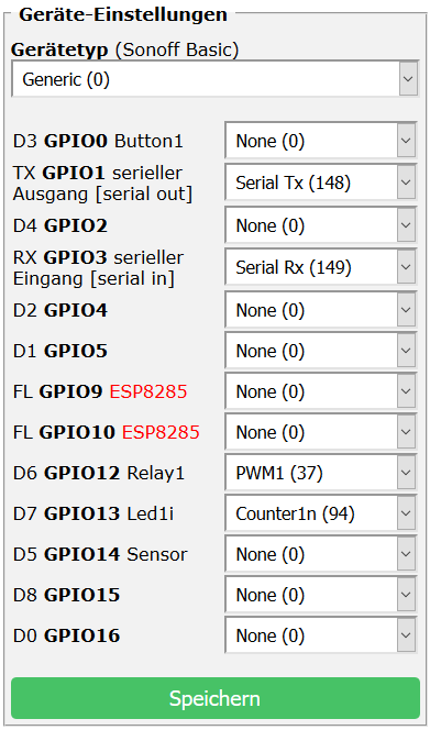
Hi, it's pretty simple:
- Serial Tx and Rx setup as shown in the Generic Module pic above and then
- in Tasmota Console:
Baudrate 9600
SerialSend5 FF55FF05DC0A
SerialSend5 FF550005DC0A
SerialSend5 FF558005DC0A
... and so on.
BTW the 'switch issue' seems to be because ESP GPIO13
is also connected to MCU Pin10.
Is long press dimming even a possibility with tasmota?
I think in the depths of the Tasmota source it is possible ;),
but hardly only with rules.
thxthx0
on 19 Jun 2019
@thxthx0 Thanks again!!!
jsponz
on 19 Jun 2019
Since I only got the device today I am playing with the default f/w before I hack it.
When I 1st turned it on I skipped configuration with the tuya app and went straight to testing switch functions... and now I cannot get back to pairing mode.
I tried both (!) of the reset methods in the instructions but neither worked for me. (hold switch for 10+ secs, switch on/off 5 times)
Any idea how to reset the device to pairing mode? (with original tuya f/w)
james-fry
on 19 Jun 2019
It works great, but I have some questions (sorry but I am not an expert in Tasmota... yet):
- After rebooting the device, the baudrate is lost and I have to enter it again via console. How can I store this value?
- Switch is not working here. I have the same wiring as with the original f/w but with Tasmota, it makes nothing.
Thanks!
jsponz
on 20 Jun 2019
Hi finally I managed to get the dimmer flashed by wire.
I have tasmota running now, set up as:

And wired as:

But when I send the commands via the console nothing happens...:(
09:59:23 MQT: tele/%topic%/INFO3 = {"RestartReason":"Power on"}
09:59:31 MQT: tele/%topic%/STATE = {"Time":"2019-06-20T09:59:31","Uptime":"0T00:00:14","Vcc":3.182,"SleepMode":"Dynamic","Sleep":50,"LoadAvg":20,"Wifi":{"AP":2,"SSId":"XXXXX","BSSId":"XXXXXXXXXXXXXX","Channel":11,"RSSI":54,"LinkCount":1,"Downtime":"0T00:00:04"}}
10:01:15 CMD: Baudrate 9600
10:01:15 MQT: stat/%topic%/RESULT = {"Baudrate":9600}
10:01:32 CMD: SerialSend5 FF55FF05DC0A
10:01:32 MQT: stat/%topic%/RESULT = {"SerialSend":"Done"}
10:01:40 CMD: SerialSend5 FF550005DC0A
10:01:40 MQT: stat/%topic%/RESULT = {"SerialSend":"Done"}
10:01:48 CMD: SerialSend5 FF558005DC0A
10:01:48 MQT: stat/%topic%/RESULT = {"SerialSend":"Done"}
10:02:01 MQT: tele/%topic%/UPTIME = {"Time":"2019-06-20T10:02:00","Uptime":"0T00:02:43"}
I once tested it and it's great! But the problem is that you can not dim LEDS with it :-( lightbulb goes .... what have you already tested?
dr-apple
on 20 Jun 2019
I have tested with a 12v LED powersupply and a 12v LED behind it, but I measured the voltage output, and there is none.
HA-TB303
on 20 Jun 2019
I have tested with several LED bulbs and it works. I have tested with LED bulbs and transformer.
jsponz
on 20 Jun 2019
@jsponz please post a link for the led und trafo ;-)
dr-apple
on 20 Jun 2019
Here a video for my LED and Trafo tests: https://youtu.be/8gcd-AqhbHE
dr-apple
on 20 Jun 2019
Sure. I will do it tomorrow ;-)
jsponz
on 20 Jun 2019
@jsponz thanks ;-)
dr-apple
on 20 Jun 2019
I have watched your video. From my experience, the trafo is critical. In some cases, on the trafo, they use to write "flicker free".
I will send you pictures.
jsponz
on 20 Jun 2019
With stock tuya f/w its working fine for my 0-100% with a philips dimmable LED bulb
james-fry
on 20 Jun 2019
Yes, also think that it lies on the transformer, the LEDs are dimmable ...
dr-apple
on 20 Jun 2019
@james-fry is the p. led on a trafo or directly on 230V ?
dr-apple
on 20 Jun 2019
Hi, you can and must use halogen or normal incandescent light bulbs,
dimmable LED light bulbs, dimmable LED transformers, dimmable power supplies...
e.g. https://www.amazon.de/s?k=led+trafo+dimmbar
@jsponz:
baudrate isn't lost in my setup (?)
but you can define a rule to set baudrate every startup
Rule1 1
Rule1 on System#Boot do Baudrate 9600 endon
for switch you need a virtual relay (e.g. Relay1 @ GPIO14) and rule,
but don't expect to much, it might work five times out of ten atm.
Rule2 1
Rule2 on Power1#State=0 do SerialSend5 FF 55 00 05 DC 0A endon on Power1#State=1 do SerialSend5 FF 55 FF 05 DC 0A endon
@HA-TB303:
I can't see any error, maybe a bad connection...
thxthx0
on 20 Jun 2019
@james-fry is the p. led on a trafo or directly on 230V ?
Dimmable bulb directly in 240v
james-fry
on 20 Jun 2019
@thxthx0 thank you for this info: https://www.amazon.de/s?k=led+trafo+dimmbar
dr-apple
on 20 Jun 2019
Got my WiFi Dimmer today and flashed it successfully with Tasmota,
it's workin'...I had to set pin RE (= STM8 MCU Pin4 NRST) to GND for backup and flash
(and also GPIO0 to GND for flash mode) - didn't try Tuya-Convert.
Can I ask what setup you used to flash ?
TTL/Serial USB ? 3.3v or 5v ?
Which tool ?
Will have another go at mine !
DeanoXX
on 20 Jun 2019
@jsponz please post a link for the led und trafo ;-)
As promised the pictures:
1) This is with a "flicker free" trafo:

2) This is a 220V dimmable LED from Sylvania:

3) This is a good quality dimmable LED driver:

I hope that helps.
jsponz
on 21 Jun 2019
Yes thank very much...
How do we still get the dimming by push button? And when that's done, how do we get that as a finished device in Tasmota? I mean that you can use it normally and the serial commands?
Thanks again to all contributors here !!!
dr-apple
on 21 Jun 2019
how do we get that as a finished device in Tasmota?
Hopefully with the help of the coders here and
perhaps an 'open issue' so it can be seen :)
Can I ask what setup you used to flash ?
I've used nothing special,
CP2102 USB-TTL Adapter @ 3.3V
and esptool.
Reading and writing is also possible with
ESP/MCU module soldered to the dimmer pcb
(just flashed my backup for testing).
thxthx0
on 21 Jun 2019
But when I send the commands via the console nothing happens...:(
09:59:23 MQT: tele/%topic%/INFO3 = {"RestartReason":"Power on"}
09:59:31 MQT: tele/%topic%/STATE = {"Time":"2019-06-20T09:59:31","Uptime":"0T00:00:14","Vcc":3.182,"SleepMode":"Dynamic","Sleep":50,"LoadAvg":20,"Wifi":{"AP":2,"SSId":"XXXXX","BSSId":"XXXXXXXXXXXXXX","Channel":11,"RSSI":54,"LinkCount":1,"Downtime":"0T00:00:04"}}
10:01:15 CMD: Baudrate 9600
10:01:15 MQT: stat/%topic%/RESULT = {"Baudrate":9600}
10:01:32 CMD: SerialSend5 FF55FF05DC0A
10:01:32 MQT: stat/%topic%/RESULT = {"SerialSend":"Done"}
10:01:40 CMD: SerialSend5 FF550005DC0A
10:01:40 MQT: stat/%topic%/RESULT = {"SerialSend":"Done"}
10:01:48 CMD: SerialSend5 FF558005DC0A
10:01:48 MQT: stat/%topic%/RESULT = {"SerialSend":"Done"}
10:02:01 MQT: tele/%topic%/UPTIME = {"Time":"2019-06-20T10:02:00","Uptime":"0T00:02:43"}
I've flashed my dimmer with Tasmota, connected a halogen bulb and setup with your settings. The commands works just fine here (they turn on/off the bulb with various brightness)!
I would love to see a proper implementation of this! Let me know if I can be of any help.
 henrikwils
on 25 Jun 2019
henrikwils
on 25 Jun 2019
Have you tested with the original firmware?
In my case, two units were faulty with the original firmware.
jsponz
on 25 Jun 2019
Have you tested with the original firmware?
In my case, two units were faulty with the original firmware.
I didn't see any problem like the one you reported with the original firmware at all. Everything worked like you would expect it to.
The switch would turn on the light at the previous brightness. Quick switch would turn on/off, and holding would adjust the brightness first down, then up. My unit was ordered back in February and this was on the shipped firmware. I never configured it in SmartLife, risking a forced firmware upgrade that would break Tuya-Convert.
But now it's flashed, and I didn't make a backup, so I can't test any further on the original firmware.
henrikwils
on 25 Jun 2019
It looks like to support this dimmer, a new template, based I would imagine upon the below:
https://github.com/arendst/Sonoff-Tasmota/blob/development/sonoff/xdrv_16_tuyadimmer.ino
Would be needed...?
 dbrb2
on 2 Jul 2019
dbrb2
on 2 Jul 2019
Yes please make it ;-)
dr-apple
on 2 Jul 2019
No idea if I can. But I will try...which may or may not get anywhere!
dbrb2
on 2 Jul 2019
@dbrb2 yes, pleaaaaaaaase try it :-)
It's a lot easier than in xdrv_16_tuyadimmer.ino
no heartbeat, no conf, no queries, no state, ...
Only communication in one direction from ESP8266 TX to STM8 MCU RX with the commands mentioned above.
The switch input S at GPIO13 should be programmed as a Counter:
50Hz pulses to be counted depending on how long the push button is pressed
(hence the issue when using GPIO13 as a 'Switch/Button Input').
thxthx0
on 2 Jul 2019
Interesting thread, I just received the same device but will hold off on playing with it for a bit.
If there is any way I can contribute to further development (partly fund needed test units, etc), I am happy to do that.
It would be great if these devices could at some point be supported 'out of the box' (or 'straight-after-flashing') in tasmota, including the much wanted long-press dimming.
 DaafSamson
on 4 Jul 2019
DaafSamson
on 4 Jul 2019
Ditto
xbmcnut
on 4 Jul 2019
I'm also happy to test since I seem not to be able to "factory reset" my device with original f/w.
I never paired it to my wifi/tuya account before playing with manual dimming, and now because I cannot reset to the pairing process the device has become essentially a dumb dimmer at the moment.
james-fry
on 4 Jul 2019
I'm not certain I am going to be able to fix this myself - I'm just not familiar enough with the code...so whilst I might try, if there is anyone with more experience than me (most people) then they would be most welcome!
dbrb2
on 4 Jul 2019
Thanks to you all I've got this working as a dimmer in Home Assistant with some rules and PWM1 set to GPIO12 (any unused should be possible). (For now I configured the switch input as a counter..)
For correct Home Assistant recognition:
SetOption59 1 - This enables sending of tele//STATE on POWER and light related commands
To set baudrate on boot:
rule1 on System#Boot do Baudrate 9600 endon
On Power ON set to full brightness, on OFF set to zero brightness
rule2 on Power1#State=0 do SerialSend5 FF 55 00 05 DC 0A endon on Power1#State=1 do SerialSend5 FF 55 FF 05 DC 0A endon
On change of dimmer set brightness (works only to a brightness level of 99)
rule3 on Dimmer#State>=10 do SerialSend5 FF 55 %value% 05 DC 0A endon on Dimmer#State<10 do SerialSend5 FF 55 0%value% 05 DC 0A endon
On Power ON I'd like to set it to the last brightness level but I can not figure out how to read the Dimmer#State on Power1#State=1 and then use the value of Dimmer#State in SerialSend.
Is it possible to scale the brightness of the dimmer to HEX format?
 ljan
on 21 Jul 2019
ljan
on 21 Jul 2019
Hi, with the BIG help of gemu2015 and some additions to his awesome Tasmota Script Editor
I've managed to write a working WiFi Dimmer script (works almost the same as the original firmware)
and i'll soon post it for further testing and improvement...
see here: https://github.com/arendst/Sonoff-Tasmota/issues/6085
thxthx0
on 21 Jul 2019
Hi, Script and config ->
https://github.com/arendst/Sonoff-Tasmota/issues/6085#issuecomment-513916678
thxthx0
on 22 Jul 2019
Hello! Thank you very much for this implementation! For those that can not flash, just try with TTL/Serial USB 5v
 ondoteam
on 28 Jul 2019
ondoteam
on 28 Jul 2019
@thxthx0 I found a problem using HA. My english is not very good, so I will do my best.
[Enviroment]
Tasmota: 6.6.0.3 20190725 using Scripts instead Rules with SetOption19 1
HA: 0.96.5
[Problem]
Everything working fine but the slider at time of set brightness 0
[How to reproduce]
1.- Go to HA and select the Dimmer entity.
2.- Turn it on using the button or the slider.
3.- Set the slider to the mininum and there is no more response from the device.
[Workaround]
Reboot the device using the Tasmota WebUI.
ondoteam
on 28 Jul 2019
@thxthx0 it is fixed in https://github.com/arendst/Sonoff-Tasmota/issues/6085#issuecomment-516117908 maybe you can update the txt file. Thank you!
ondoteam
on 29 Jul 2019
@thxthx0 I have one question for you.
I have finally flashed Tasmota (6.6.0.7) on two dimmers.
I have followed the instructions from https://blakadder.github.io/templates/qs-wifi_D01_dimmer.html
I am using the script version 0.3
From console:
00:00:00 CFG: Loaded from flash at F4, Count 16
00:00:00 Script: performs "SerialSend5 FF550005DC0A"
00:00:00 RSL: stat/sonoff/RESULT = {"SerialSend":"Done"}
00:00:00 Script: performs "Dimmer 0.00"
00:00:00 RSL: stat/sonoff/RESULT = {"POWER":"OFF","Dimmer":0}
00:00:00 Project sonoff Sonoff Version 6.6.0.7(sonoff)-STAGE
00:00:00 > WiFi-Dimmer-Script-v0.3 <
00:00:00 Script: performs "Counter1 0"
00:00:00 RSL: stat/sonoff/RESULT = {"Counter1":0}
00:00:00 Script: performs "Baudrate 9600"
00:00:00 RSL: stat/sonoff/RESULT = {"Baudrate":9600}
00:00:00 Script: performs "SerialSend5 FF559a05DC0A"
00:00:00 RSL: stat/sonoff/RESULT = {"SerialSend":"Done"}
00:00:00 Script: performs "Dimmer 70.00"
00:00:00 RSL: stat/sonoff/RESULT = {"POWER":"ON","Dimmer":70}
00:00:01 Script: performs "SerialSend5 FF550005DC0A"
00:00:01 RSL: stat/sonoff/RESULT = {"SerialSend":"Done"}
00:00:01 Script: performs "Dimmer 0.00"
00:00:01 RSL: stat/sonoff/RESULT = {"POWER":"OFF","Dimmer":0}
00:00:01 WIF: Connecting to AP1 xyz in mode 11N as sonoff-4796...
00:00:05 WIF: Connected
00:00:05 HTP: Web server active on sonoff-4796 with IP address 192.168.1.228
20:28:00 Script: performs "SerialSend5 FF559a05DC0A"
20:28:00 RSL: stat/sonoff/RESULT = {"SerialSend":"Done"}
20:28:00 Script: performs "Dimmer 70.00"
20:28:00 RSL: stat/sonoff/RESULT = {"POWER":"ON","Dimmer":70}
20:28:00 RSL: stat/sonoff/RESULT = {"POWER":"ON"}
20:28:00 RSL: stat/sonoff/POWER = ON
20:28:01 Script: performs "SerialSend5 FF550005DC0A"
20:28:01 RSL: stat/sonoff/RESULT = {"SerialSend":"Done"}
20:28:01 Script: performs "Dimmer 0.00"
20:28:01 RSL: stat/sonoff/RESULT = {"POWER":"OFF","Dimmer":0}
20:28:01 RSL: stat/sonoff/RESULT = {"POWER":"OFF"}
20:28:01 RSL: stat/sonoff/POWER = OFF
20:28:11 Script: performs "SerialSend5 FF559a05DC0A"
20:28:11 RSL: stat/sonoff/RESULT = {"SerialSend":"Done"}
20:28:11 Script: performs "Dimmer 70.00"
20:28:11 RSL: stat/sonoff/RESULT = {"POWER":"ON","Dimmer":70}
20:28:14 Script: performs "SerialSend5 FF550005DC0A"
20:28:14 RSL: stat/sonoff/RESULT = {"SerialSend":"Done"}
20:28:14 Script: performs "Dimmer 0.00"
20:28:14 RSL: stat/sonoff/RESULT = {"POWER":"OFF","Dimmer":0}
20:30:27 Script: performs "SerialSend5 FF559a05DC0A"
20:30:27 RSL: stat/sonoff/RESULT = {"SerialSend":"Done"}
20:30:27 Script: performs "Dimmer 70.00"
20:30:27 RSL: stat/sonoff/RESULT = {"POWER":"ON","Dimmer":70}
20:30:27 RSL: stat/sonoff/RESULT = {"POWER":"ON"}
20:30:27 RSL: stat/sonoff/POWER = ON
20:30:28 Script: performs "SerialSend5 FF550005DC0A"
20:30:28 RSL: stat/sonoff/RESULT = {"SerialSend":"Done"}
20:30:28 Script: performs "Dimmer 0.00"
20:30:28 RSL: stat/sonoff/RESULT = {"POWER":"OFF","Dimmer":0}
20:30:28 RSL: stat/sonoff/RESULT = {"POWER":"OFF"}
20:30:28 RSL: stat/sonoff/POWER = OFF
As you see button is working. But the slider from mainpage is not working (counter is working), although values are sent (as you see on the console).
But the worst thing is that the light is not working. Neither toggle nor dimming. LED Bulb is working and dimmable.
Connection of the LED bulb is ok.
That happens on two dimmers! Any idea!
Thanks!
jsponz
on 25 Aug 2019
@jsponz
Hi, does dimming still work with stock firmware?
It sounds like an issue with the STM8 MCU
(maybe bridge RE--GND not removed...)
thxthx0
on 26 Aug 2019
Hi, it was working before flashing. I tested it one device.
Could you explain further this?
"It sounds like an issue with the STM8 MCU
(maybe bridge RE--GND not removed...)"
Thanks!
jsponz
on 26 Aug 2019
STM8 MCU is the second microcontroller on the board, it receives the dimming commands from the ESP chip.
For serial flashing pin RE has to be grounded and bridge removed afterwards.
Did you flash OTA or via serial adapter?
OTA often has problems because the flash isn't completely erased before.
So my advice:
full erase (with esptool.py or NodeMCU-PyFlasher)
and then give this bin a try (all configuration and script included)
http://forum.creationx.de/index.php?attachment/4440-sonoff-tasmota-dev-6-6-0-6-de-dimmerscript-1mb-zip/
thxthx0
on 26 Aug 2019
@thxthx0 Thanks!
That was my mistake! I forgot to remove the bridge.
Two more things:
1) I flashed it via serial adapter. I flashed version 6.6.0.7. If I try to flash your file via OTA I get:
"Upload Failed - Program flash size is larger than real flash size".
Is it safe to do it better via serial adapter?
2) With my version (6.6.0.7) and the script, when switching off, the LED bulb is still on (very low, but on). What should I change on the script?
Thanks!
jsponz
on 26 Aug 2019
@thxthx0 I have tested it with the second device and it works as expected. I guess that the hardware of the first device is not 100 % ok. With an incandescent bulb it works though.
jsponz
on 26 Aug 2019
@jsponz
In order to update the firmware, there needs to be sufficient free program memory to hold both the current firmware binary and the updated firmware binary concurrently. The active firmware loads the new binary and then "passess control" to the new version. If you try to load a file that is bigger than the free space...
To achieve the update, one needs to free up program memory first. Tasmota is able to do this by loading a small file (sonoff-minimal.bin ~365K) binary whose sole purpose is to remain connected to Wi-Fi and then load a new binary. Tasmota checks the available free memory and if the new firmware is too large, it reacts accordingly... it either reports that there is insufficient free memory, or ...
Tasmota provides two mechanisms for performing a firmware update wirelessly - web OTA and file upload. If you perform a web OTA, Tasmota checks the free memory and, if required, handles the intermediate sonoff-minimal.bin update automatically. It then loads the "full" firmware binary. If one uses the File upload method, then one must handle the intermediate "minimal" update manually before then uploading the "full" version.
Mike
meingraham
on 26 Aug 2019
@meingraham Thanks!
jsponz
on 26 Aug 2019
@jsponz
If I remember right, some people had the same problem with stock firmware
when switching off and the bulb still on a bit... they got refund.
The Tasmota binary from above can't be flashed OTA,
it's a 1MB backup file for serial programming (minimal.bin doesn't help).
thxthx0
on 26 Aug 2019
@thxthx0
Yes, I was one of them :-(
I will flash it via serial programming. For the moment, version 6.6.07 works fine 👍
jsponz
on 26 Aug 2019
@jsponz Could you reiterate the exact steps to get it working, for those of us considering buying a few of these devices? ;-) thanks a lot in advance!
 jypma
on 7 Sep 2019
jypma
on 7 Sep 2019
@jypma
Hi, instructions at the Template Repository:
Moes QS-WiFi-D01 Dimmer 150W Dimmer
If there are any further questions, plz feel free to ask here or at https://github.com/arendst/Sonoff-Tasmota/issues/6085
thxthx0
on 8 Sep 2019
@jypma as @thxthx0 suggests, please use the template repository as guideline. It is well documented and I even follow myself :-)
@thxthx0 thanks for the message :-)
jsponz
on 8 Sep 2019
@jypma
Hi, instructions at the Template Repository:
Moes QS-WiFi-D01 Dimmer 150W DimmerIf there are any further questions, plz feel free to ask here or at #6085
Awesome work guys! it's a bit of work all together but following the guide I got things up and running. Much impressed by the work that has gone in to this!
Thank you!
DaafSamson
on 23 Sep 2019
i get an issue when i try to insert the script in my script editor
"use only 1536 signs"
What can i do?
 flinke-flasche
on 26 Sep 2019
flinke-flasche
on 26 Sep 2019
Your script is too long. You need to optimize if possible. Check the Script Cookbook for some ideas.
meingraham
on 26 Sep 2019
i got it.
it was too late.
can i change the speed with "dimstp="
i can see a change with my eyes :-(
flinke-flasche
on 26 Sep 2019
@flinke-flasche
yes, you can try changes in:
dimmlp=1.7 ;dim multiplier 1..2.55
dimstp=2 ;dim step/speed 1..5
depending on your light bulb...
thxthx0
on 26 Sep 2019
i don't see any changes when i play with these values.
:-(
flinke-flasche
on 26 Sep 2019
What's your device,
is it dimmable or did it work as expected with the dimmer and stock Tuya firmware?
Is the script enabled?
thxthx0
on 26 Sep 2019
i have the Moes Wifi Dimmer like this one
https://blakadder.github.io/templates/qs-wifi_D01_dimmer.html
i flashed the Tasmota firmware and everything runs like it should.
But the dimming time could be a bit longer.
Can i use this with HTTP Get commands?
@ thxthx0
bist du aus Deutschland?
flinke-flasche
on 26 Sep 2019
i found the http commands to control it over IP:
http://yourIP/cm?cmnd=Dimmer%2050 for Dimmer 50
http://yourIP/cm?cmnd=Power%20on for on
http://yourIP/cm?cmnd=Power%20off for off
flinke-flasche
on 26 Sep 2019
You mean even slower dimming than with dimstp=1?
you can set delays in the script
after dimval+=dimstp and dimval-=dimstp (line 71 and 80) e.g.,
...
dimval+=dimstp
delay(100)
...
you'll have to delete some comments to have enough space.
ja, gut möglich, dass ich aus DE bin ;)
thxthx0
on 26 Sep 2019
Yes.
I tried, but its as fast as before :-(
My favorite is when the Dimmer takes 5 seconds from 100 to 0, and reverse.
like this?
...
; increase dim level
dimval+=dimstp
delay(100)
if dimval>dimul
then
; upper limit
dimval=dimul
endif
=#senddim(dimval)
else
; decrease dim level
dimval-=dimstp
delay(100)
if dimval
...
flinke-flasche
on 26 Sep 2019
yes,
delay(100) will even take more than 5sec
thxthx0
on 26 Sep 2019
not in my case :-(
i can't dimm down to 1.
the last i can dimm is down to 7
flinke-flasche
on 26 Sep 2019
push button or webinterface slider?
the limits for button control are set by:
dimll=15 ;dim lower limit min. 0
dimul=95 ;dim upper limit max. 100
thxthx0
on 26 Sep 2019
Webinterface, normal light bulb 40 watt
when i use
dimmlp=1
dimstp=1
delay(500)
the brightness of my light bulb is not as bright as it can be.
But it might be slower.
flinke-flasche
on 26 Sep 2019
So if I'm right, you want a delay by slider control in the webinterface?
and I'm talking all the time about button control ;)
thxthx0
on 26 Sep 2019
yes you're semi right.
I want to control my dimmers over http like http://yourIP/cm?cmnd=Dimmer%2050
Maybe it should be the same like the web slider.
I try the button, and its very very slow :-D
flinke-flasche
on 26 Sep 2019
Okay, then plz forget everything we discussed earlier and take the default params again.
In the WebUI the dim values are adressed directly and changed from one value to the wanted.
for example: actual value is 20 -> you move the slider to 80 -> then there are no steps in between
-> there is only a coded soft dimming by the second microcontroller (STM8), that can't be influenced in Tasmota.
So for a delay you would have to code additional steps (between 20 and 80) e.g., additional http requests........
I'm out now :)
thxthx0
on 26 Sep 2019
ok, thank you, i'll test it.
flinke-flasche
on 26 Sep 2019
Do you know why i can dim the bulb with the button down to 0, but with the web interface only down to 7?
flinke-flasche
on 26 Sep 2019
not really, all my sliders work from 0 to 100.
you could try Reset 5 and a clean new setup in Tasmota
or a complete flash erase esptool.py erase_flash and new flashing.
thxthx0
on 27 Sep 2019
this is with all my three devices.
all were new flashed by myself.
maybe i have a issue in my script
...
D
sw=0
tmp=0
cnt=0
tmr=0
hold=0
powert=0
slider=0
dim=""
shortprl=2
shortpru=10
dimdir=0
dimmlp=2.55
dimstp=1
dimll=0
dimul=100
dimval=100
...
flinke-flasche
on 27 Sep 2019
your config from above is ok and has no influence on the slider.
but plz try with a clean setup as suggested, to see if the slider issue still exists -
after that you can make changes...
thxthx0
on 27 Sep 2019
Hello,
i have this dimmer and it works fine with the script
https://github.com/arendst/Sonoff-Tasmota/files/3476824/WiFi-Dimmer-Script-v0.3.txt
the only thing that bothers me is the slider in the web ui.
the slider does not show the actual dim level if i change it with the button connected to "S"
What do i have to change in the script to have the slider always on the actual dim level?
 ChrisROL
on 11 Oct 2019
ChrisROL
on 11 Oct 2019
@ChrisROL
the slider does not show the actual dim level if i change it with the button connected to "S"
Hi, I'm not quite sure, but I think that's a basic issue with sliders in WebUI.
When you click the refresh button in the web browser, the updated slider will be displayed.
If you're using home automation software, that's no problem either - sliders move as they should.
thxthx0
on 12 Oct 2019
the slider does not show the actual dim level if i change it with the button connected to "S"
As designed indeed. See above response from @thxthx0
 arendst
on 12 Oct 2019
arendst
on 12 Oct 2019
@thxthx0 I'm hacking on a dimmer right now, working from the template page Thanks a lot for your awesome work! :-)
I think one of the pictures may have the labelling in the wrong order along the bottom: GND, RE, (), (), +3V3 seem to be backwards w.r.t. to the silkscreen that's on the backside.
Shouldn't it be (according to the silkscreen, which you also show in the next picture) +3V3, POA, PCK, RE, GND, when seen from that side? i.e. +3V3 is the pin directly flush with the side of the board.
jypma
on 24 Oct 2019
Shame on me 😞 . You're right @jypma , I didn't notice at all.
Thanks a lot, will do a PR...
Here the corrected pic:
thxthx0
on 24 Oct 2019
Take a look at #6758 and https://github.com/arendst/Tasmota/wiki/TuyaMCU for new features
 blakadder
on 27 Oct 2019
blakadder
on 27 Oct 2019
Odd....working well for me on multiple devices, but on one, which has apparently flashed and works fine, every time I toggle the switch (either via the app or the switch) the unit restarts
Flashed another unit, and the same synmptoms
Makes no difference what the load is (or none)
As soon as the switch is turned off again, the unit returns to normal operation
Any ideas? It sounds like the switch being on is somehow affecting the ability of the micro-controller to run...
Interestingly though, even with the script disabled, meaning that there are no messages being sent to the dimmer module, clicking "toggle" still causes the unit to restart
dbrb2
on 9 Nov 2019
most likely a bad flash so the device crashes and reboots
blakadder
on 9 Nov 2019
So possibly just bad luck it happened twice in same location.
I have reflashed though, without success, so it may be something that
survives a standard reflash
I'll have another go :-)
On Sat, 9 Nov 2019, 12:12 blakadder, notifications@github.com wrote:
most likely a bad flash so the device crashes and reboots
—
You are receiving this because you were mentioned.
Reply to this email directly, view it on GitHub
https://github.com/arendst/Tasmota/issues/5737?email_source=notifications&email_token=AABFQ42ZY7RJPQRNLYEIOULQS2SKTA5CNFSM4HJ42QK2YY3PNVWWK3TUL52HS4DFVREXG43VMVBW63LNMVXHJKTDN5WW2ZLOORPWSZGOEDUESUI#issuecomment-552094033,
or unsubscribe
https://github.com/notifications/unsubscribe-auth/AABFQ4ZIMA72OPKQ3MZWV6LQS2SKTANCNFSM4HJ42QKQ
.
dbrb2
on 9 Nov 2019
Yes, and there is always the chance of strange issues without a full erase
(before flashing / not possible OTA with Tuya Convert).
thxthx0
on 9 Nov 2019
Interestingly, I have replaced the unit, and it is now working as expected
- no crash on switch.
However, the unit does reliably respond to pings more slowly when turned on
- though we are talking 100mS ping response when on, and 10mS response when
off - so not actually a problem...just interesting
On Sat, Nov 9, 2019 at 12:28 PM thxthx0 notifications@github.com wrote:
Yes, and there is always the chance of strange issues without a full erase
(before flashing / not possible OTA with Tuya Convert).—
You are receiving this because you were mentioned.
Reply to this email directly, view it on GitHub
https://github.com/arendst/Tasmota/issues/5737?email_source=notifications&email_token=AABFQ45PO5PMG6UXYKJQRFDQS2UE7A5CNFSM4HJ42QK2YY3PNVWWK3TUL52HS4DFVREXG43VMVBW63LNMVXHJKTDN5WW2ZLOORPWSZGOEDUE27Q#issuecomment-552095102,
or unsubscribe
https://github.com/notifications/unsubscribe-auth/AABFQ42PXQWBBTUXN6E6Q3DQS2UE7ANCNFSM4HJ42QKQ
.
dbrb2
on 9 Nov 2019
It looks like you were onto something. Of ~13 devices flashed using
tuya-convert, all worked, but 2 responded extremely slowly when toggled.
Both of these devices, after a local flash over copper, worked fine
So something odd was going on - not enough to prevent the firmware from
working, but enough to prevent it working well, and only on a small number
of devices :-)
On Sat, Nov 9, 2019 at 12:45 PM Ben Barker ben@bbarker.co.uk wrote:
Interestingly, I have replaced the unit, and it is now working as expected
- no crash on switch.
However, the unit does reliably respond to pings more slowly when turned
on - though we are talking 100mS ping response when on, and 10mS response
when off - so not actually a problem...just interestingOn Sat, Nov 9, 2019 at 12:28 PM thxthx0 notifications@github.com wrote:
Yes, and there is always the chance of strange issues without a full erase
(before flashing / not possible OTA with Tuya Convert).—
You are receiving this because you were mentioned.
Reply to this email directly, view it on GitHub
https://github.com/arendst/Tasmota/issues/5737?email_source=notifications&email_token=AABFQ45PO5PMG6UXYKJQRFDQS2UE7A5CNFSM4HJ42QK2YY3PNVWWK3TUL52HS4DFVREXG43VMVBW63LNMVXHJKTDN5WW2ZLOORPWSZGOEDUE27Q#issuecomment-552095102,
or unsubscribe
https://github.com/notifications/unsubscribe-auth/AABFQ42PXQWBBTUXN6E6Q3DQS2UE7ANCNFSM4HJ42QKQ
.
dbrb2
on 9 Nov 2019
Interesting...
This evening, all units were unresponsive to local button presses, after
working fine for over a day.
I power cycled them, and all came back up.
I have now enabled syslog on a few of them to see if the issue recurs....
On Sat, Nov 9, 2019 at 3:10 PM Ben Barker ben@bbarker.co.uk wrote:
It looks like you were onto something. Of ~13 devices flashed using
tuya-convert, all worked, but 2 responded extremely slowly when toggled.Both of these devices, after a local flash over copper, worked fine
So something odd was going on - not enough to prevent the firmware from
working, but enough to prevent it working well, and only on a small number
of devices :-)On Sat, Nov 9, 2019 at 12:45 PM Ben Barker ben@bbarker.co.uk wrote:
Interestingly, I have replaced the unit, and it is now working as
expected - no crash on switch.However, the unit does reliably respond to pings more slowly when turned
on - though we are talking 100mS ping response when on, and 10mS response
when off - so not actually a problem...just interestingOn Sat, Nov 9, 2019 at 12:28 PM thxthx0 notifications@github.com wrote:
Yes, and there is always the chance of strange issues without a full
erase
(before flashing / not possible OTA with Tuya Convert).—
You are receiving this because you were mentioned.
Reply to this email directly, view it on GitHub
https://github.com/arendst/Tasmota/issues/5737?email_source=notifications&email_token=AABFQ45PO5PMG6UXYKJQRFDQS2UE7A5CNFSM4HJ42QK2YY3PNVWWK3TUL52HS4DFVREXG43VMVBW63LNMVXHJKTDN5WW2ZLOORPWSZGOEDUE27Q#issuecomment-552095102,
or unsubscribe
https://github.com/notifications/unsubscribe-auth/AABFQ42PXQWBBTUXN6E6Q3DQS2UE7ANCNFSM4HJ42QKQ
.
dbrb2
on 11 Nov 2019
Uhm.... question about the Switch:
The S switch input is intended for push-button / conventional momentary switch control and detects the mains frequency when the button is pressed.
I already have a dimmer in the wall.... this one any idea what would happen if i connect that?
I assume the switch/dimmer is not capable of using this input when no input from the ESP8266 is active?
Would also cause issues that if you turn it on via wallbutton, dim, and then change and turn it off via HTTP it would not turn off the Wallbutton but simply ignore its value, meaning next time the wall button is pressed it will not turn on but stay off instead.
 haldi4803
on 20 Nov 2019
haldi4803
on 20 Nov 2019
Hi Haldi,
(are you from Haldi, Schattdorf in Switzerland?). To use a Feller Dimmer as an input I would suggest removing the whole Feller hardware behind the the white wheel and connect it to a push button rotary encoder (aliexpress). The connect the rotary encoder to the ESP8266 inside the dimmer you need to solder it to VCC, GND, and three GPIOs (push button and 2x for the rotary encoder).
In theory:
Without modifications the phase cut 230V waveform signal of the Feller dimmer would show up on GPIO13 when connected to the Switch input of the dimmer as follows:
0-50% dimming: constant high on GPIO13, same as a non pressed momentary switch
50-100% dimming: periodic rectangular high-low signal, same as a pressed momentary switch
 mgoeller
on 20 Nov 2019
mgoeller
on 20 Nov 2019
I have flashed this device, but the secondary MCU seems to be giving me problems.
I did a full erase prior to flashing the ESP unit.
Pushing serial commands to the secondary MCU works fine and the light bulb dims accordingly.
But after a few minutes the light is turned off (actually the bulb is dimmed to a very faint glow), while there is no serial command send.
It seems like the secondary MCU won't hold it setting for very long.
if the bulb is turned off, the same thing happens after a few minutes (bulb is faintly glowing).
The faint glow also seems to be the basic setting on startup of the unit.
The bulb is halogen 40W light bulb by the way.
It looks to me that the secondary MCU is spontaniously rebooting itself every few minutes.
The more frequent it receives serial data the faster it tends to reboot.
Does anyone recognize this strange behaviour??
 keesdekraker
on 23 Nov 2019
keesdekraker
on 23 Nov 2019
Does anyone recognize this strange behaviour??
@keesdekraker
Maybe a similar problem that some people had/have (light isn't turned off completely).
yes, could be a STM MCU issue (early firmware??).
Luckily, none of my dimmers have such a problem and they work the way they should,
one dimmer since three months in a mixed GU10 Halogen/LED setup.
@haldi4803
... or in other words, forget the Feller :) and replace it with
a Wifi Dimmer and a wall button to make it smart.
thxthx0
on 23 Nov 2019
Yeah.... if i find a rotary switch that has the same diameter like the wall switch so i can use the same Button/Cover as all the other buttons in the home i will do that :)
The connect the rotary encoder to the ESP8266 inside the dimmer you need to solder it to VCC, GND, and three GPIOs (push button and 2x for the rotary encoder).
This one says it needs 5V working current? does it also work with 3.3V? Don't really want to add in a different voltage circuit.
Analog input
The ESP8266 has a single analog input, with an input range of 0 - 1.0V. If you supply 3.3V, for example, you will damage the chip.
Or use something simple like this: https://www.aliexpress.com/item/32958134064.html
Use one Pin to output 1V and use the Analog Input pin. This does not have the Push function, but simply sliding it to the left would result in the same.
haldi4803
on 23 Nov 2019
Could be an early version. I have the dimmer lying around for sometime now.
Although the unit was already patched against the first version of tuya convert.
I have ordered 2 more devices, which will arrive somewhere begin of december.
I'm sure I will have better luck with the new devices.
keesdekraker
on 23 Nov 2019
I intend to use tuya-convert to flash this device. How do you put it into pairing mode? there are no buttons or led lights to give any indications
 epicurean70
on 29 Nov 2019
epicurean70
on 29 Nov 2019
- Connect a light bulb to the N and L- terminals
- Connect mains to N and L terminals
- When powered up, connect the S and L terminal for 10 seconds. The light
bulbs is starting to blink now. - The device is now in pairing mode, start tuya convert to flash tasmota
minimal binary file. - Flash your Tasmota build using the Tasmota WebUI.
Op vr 29 nov. 2019 09:59 schreef epicurean70 notifications@github.com:
I intend to use tuya-convert to flash this device. How do you put it into
pairing mode? there are no buttons or led lights to give any indications—
You are receiving this because you were mentioned.
Reply to this email directly, view it on GitHub
https://github.com/arendst/Tasmota/issues/5737?email_source=notifications&email_token=AIVBIBH5JXHLV5QF5HP2U7TQWDKYFA5CNFSM4HJ42QK2YY3PNVWWK3TUL52HS4DFVREXG43VMVBW63LNMVXHJKTDN5WW2ZLOORPWSZGOEFOIVQQ#issuecomment-559712962,
or unsubscribe
https://github.com/notifications/unsubscribe-auth/AIVBIBDCH6XTXGYXHOEAKITQWDKYFANCNFSM4HJ42QKQ
.
keesdekraker
on 29 Nov 2019
- Connect mains to N and L terminals
- When powered up, connect the S and L terminal for 10 seconds. The light
bulbs is starting to blink now.
Buy some life insurance if you plan on flashing the device while connected to mains
blakadder
on 29 Nov 2019
Tuya convert is flash ota via WiFi no?
james-fry
on 29 Nov 2019
Yes. Tuya convert is OTA. It is no risk to flash it when connected to
mains.
NEVER flash a device when connected via the serial interface!
Op vr 29 nov. 2019 10:52 schreef james-fry notifications@github.com:
Tuya convert is flash it’s via WiFi no?
—
You are receiving this because you were mentioned.
Reply to this email directly, view it on GitHub
https://github.com/arendst/Tasmota/issues/5737?email_source=notifications&email_token=AIVBIBBNMEZUD5WUB4WQUUDQWDQ57A5CNFSM4HJ42QK2YY3PNVWWK3TUL52HS4DFVREXG43VMVBW63LNMVXHJKTDN5WW2ZLOORPWSZGOEFOM5NI#issuecomment-559730357,
or unsubscribe
https://github.com/notifications/unsubscribe-auth/AIVBIBBX6J3PFAPXIDR2D7LQWDQ57ANCNFSM4HJ42QKQ
.
keesdekraker
on 29 Nov 2019
- flashed 3 devices serial with sonoff.bin (6.4.1)
- OTA flashed with 7.0.0.1
- Added the Dimmer script.
1 dimmer works OK. Not much activity on this one (on/off few times a day)
2 dimmers are activated many times by a motion detection via Node-Red MQTT to Domoticz.
These 2 dimmers started with loosing connection with Wifi.
Now they are alternating on / off in seconds:
This is the logging from the console:
15:24:49 Script: performs "SerialSend5 FF557405DC0A"
15:24:49 MQT: stat/tasmota_dimmer_overloop/RESULT = {"SerialSend":"Done"}
15:24:49 Script: performs "Dimmer 53.00"
15:24:49 MQT: stat/tasmota_dimmer_overloop/RESULT = {"POWER":"ON","Dimmer":53}
15:24:49 MQT: domoticz/in = {"idx":49,"nvalue":1,"svalue":"53","Battery":100,"RSSI":7}
15:24:49 MQT: stat/tasmota_dimmer_overloop/RESULT = {"POWER":"ON"}
15:24:49 MQT: stat/tasmota_dimmer_overloop/POWER = ON
15:24:49 Script: performs "SerialSend5 FF550005DC0A"
15:24:49 MQT: stat/tasmota_dimmer_overloop/RESULT = {"SerialSend":"Done"}
15:24:49 Script: performs "Dimmer 0.00"
15:24:49 MQT: stat/tasmota_dimmer_overloop/RESULT = {"POWER":"OFF","Dimmer":0}
15:24:49 MQT: domoticz/in = {"idx":49,"nvalue":0,"svalue":"0","Battery":100,"RSSI":7}
15:24:49 MQT: stat/tasmota_dimmer_overloop/RESULT = {"POWER":"OFF"}
15:24:49 MQT: stat/tasmota_dimmer_overloop/POWER = OFF
I disconnected the button on S to be sure that no interfecence can cause the alternating.
I tried a Reset 5 and reflashing OTA. No result.
Any idea's what is happening?
 Elmo1955
on 29 Nov 2019
Elmo1955
on 29 Nov 2019
Thanks. I do not have a bulb with me at this point. is there any other way to bring it into pairing mode?
epicurean70
on 30 Nov 2019
@Elmo1955
That seems to be an infinite loop issue with Domoticz
when triggered several times within a short period.
You can click "Restart" in Tasmota to stop the loop.
But I haven't found a real solution yet - delays and CounterDebounce don't help.
@epicurean70
You don't necessarily need a bulb, but you won't be able to recognize the pairing mode.
S connected to L for 10sec will do the job...
thxthx0
on 4 Dec 2019
Can you leave the L and S connected throughout the flashing procedure?
epicurean70
on 5 Dec 2019
@epicurean70, no. Connect them for at least 10 seconds. Use a isolated wire
with the two ends stripped. No need to fix the wire, you can make a
connection by tipping the screwheads for 10 secs.
Pay close attention! Do not come in to contact the stripped end of the
wire. And do not mistakenly connect the wrong terminals, because you can
make short and potentially break the device and blow out a fuse.
Other than that, it's a piece of cake.
Good luck!
Op do 5 dec. 2019 07:05 schreef epicurean70 notifications@github.com:
Can you leave the L and S connected throughout the flashing procedure?
—
You are receiving this because you were mentioned.
Reply to this email directly, view it on GitHub
https://github.com/arendst/Tasmota/issues/5737?email_source=notifications&email_token=AIVBIBBPISWYM75LKKUJTBDQXCKZNA5CNFSM4HJ42QK2YY3PNVWWK3TUL52HS4DFVREXG43VMVBW63LNMVXHJKTDN5WW2ZLOORPWSZGOEF7TI6I#issuecomment-561984633,
or unsubscribe
https://github.com/notifications/unsubscribe-auth/AIVBIBGRN3C72L3J77SBEGLQXCKZNANCNFSM4HJ42QKQ
.
keesdekraker
on 5 Dec 2019
@epicurean70, no. Connect them for at least 10 seconds. Use a isolated wire with the two ends stripped. No need to fix the wire, you can make a connection by tipping the screwheads for 10 secs. Pay close attention! Do not come in to contact the stripped end of the wire. And do not mistakenly connect the wrong terminals, because you can make short and potentially break the device and blow out a fuse. Other than that, it's a piece of cake. Good luck! Op do 5 dec. 2019 07:05 schreef epicurean70 notifications@github.com:
…
Can you leave the L and S connected throughout the flashing procedure? — You are receiving this because you were mentioned. Reply to this email directly, view it on GitHub <#5737?email_source=notifications&email_token=AIVBIBBPISWYM75LKKUJTBDQXCKZNA5CNFSM4HJ42QK2YY3PNVWWK3TUL52HS4DFVREXG43VMVBW63LNMVXHJKTDN5WW2ZLOORPWSZGOEF7TI6I#issuecomment-561984633>, or unsubscribe https://github.com/notifications/unsubscribe-auth/AIVBIBGRN3C72L3J77SBEGLQXCKZNANCNFSM4HJ42QKQ .
and what happened to ?

blakadder
on 5 Dec 2019
I had only 1 of 4 dimmers still working.
Now I updated the firmware with Tasmota 7.1.2.
The update seemed fine but... the slider and on/off does not have effect on the lights.
Unfortunately going back OTA to Tasmota-v7.0.0.1-w-Scripting-2.6.x-1MB.bin results in an error: Upload Failed \ Upload buffer miscompare.
This means starting with serial flash again?
Elmo1955
on 10 Dec 2019
@elmo1955
try first to flash tasmota-minimal.bin
after that flash what you need.
 Aint-Nobody
on 10 Dec 2019
Aint-Nobody
on 10 Dec 2019
@Elmo1955
try first to flash tasmota-minimal.bin
after that flash what you need.
@Aint-Nobody
Yes of course, thanks! (I should have known..)
It works again.
Elmo1955
on 10 Dec 2019
hello.
Does any one has this device and try to flash it?
https://www.aliexpress.com/item/4000218674472.html
It looks like the Moes QS-WiFi-D01 but with 2 channels.
Can this template be adapted to this model?
I'm interested in buying it, but i need to know if it can be flashed.
Thanks
 gonzasmts
on 8 Jan 2020
gonzasmts
on 8 Jan 2020
I dont have that one - which I think is the "MS-104B" - but do have the Moes MS-104 (sent to me incorrectly) which is the 1 gang version. That is NOT an ESP2866 module and wont Tuya-convert. The WiFI daughter card inside the MS-104 is "Model:WA2" - see this thread https://community.home-assistant.io/t/unkown-tuya-chip/153591 (not mine - but identical). I would fully expect the MS-104B you've linked to to be the same.
DeanoXX
on 8 Jan 2020
thanks, for your replay, i will pass that one then.
are you aware of any 2 channel dimmer of that style (to put inside the electrical box) that can be flashed?
thanks for your help
gonzasmts
on 9 Jan 2020
hi guys, I flashed my 3 wifi dimmer modules via OTA. Do I need to flash it with a special (scripting enabled) tasmota version before I can use this module? I'm not interested in the dimmer part, only on/off. Was hoping the latest tasmota was already able to toggle this device but nothing happens.
I set the device up like mentioned in https://templates.blakadder.com/qs-wifi_D01_dimmer.html using
{"NAME":"WiFi-Dimmer","GPIO":[0,148,0,149,0,0,0,0,0,42,37,0,0],"FLAG":0,"BASE":18}
 RezzZ
on 9 Jan 2020
RezzZ
on 9 Jan 2020
The On and Off are identical to Dim - just "0" and "255" with dim everything in between. All need to be sent to the 2nd MCU via serial. So yes - you need the script ability to send the 0 and 255 values for on/off just as if you wanted to DIM to anywhere in between
DeanoXX
on 10 Jan 2020
For clarity ... on = 255, off = 0
DeanoXX
on 10 Jan 2020
you can send those two values with rules only but you do need the script to get the button working
blakadder
on 10 Jan 2020
got it working using gitpod to compile a build with scripting enabled. thanks @blakadder @DeanoXX
only thing left is to see if I can also use the motion/lightsensor inside the lamp when I connect that to the switch input of the dimmer.
RezzZ
on 12 Jan 2020
Do you have any ideas about the Moes MS-105B-220? It looks like the MS-104B just with dimming capabilities (or a QS-WIFI-D01 with double channel)
I was able to flash Tasmota using TuyaConvert 2.3, however I can't find the right template to use. The settings for MS-105-1 V2 do not work, nor do the MS-104B-1 scripts.
I have flashed Tasmota 8.1.0.4 with scripting enabled
 fodi666
on 17 Jan 2020
fodi666
on 17 Jan 2020
I dont have that one - which I think is the "MS-104B" - but do have the Moes MS-104 (sent to me incorrectly) which is the 1 gang version. That is NOT an ESP2866 module and wont Tuya-convert. The WiFI daughter card inside the MS-104 is "Model:WA2" - see this thread https://community.home-assistant.io/t/unkown-tuya-chip/153591 (not mine - but identical). I would fully expect the MS-104B you've linked to to be the same.
I think it depends which one you get. I got this one: https://www.banggood.com/MoesHouse-DIY-WiFi-Smart-2-Way-2-Gang-Light-LED-Dimmer-Module-Smart-Switch-Smart-LifeTuya-APP-Remote-Control-Work-with-Alexa-Google-Home-p-1591703.html?utm_design=39&utm_source=emarsys&utm_medium=PPpendingorders&utm_campaign=trigger-emarsys&utm_content=linux&sc_src=email_2650027&sc_eh=abf4a19a74a016c31&sc_llid=1297687&sc_lid=104156988&sc_uid=2wPKBip6Bt&cur_warehouse=CN
and the chip is a LM1 which i believe can be flashed with tasmota. I haven't flashed it yet because the lack of script for these dimmers with 2 channels. I'll try to make sense of the existing script(for 1 channel) and see what I can do.
 lutierigb
on 18 Jan 2020
lutierigb
on 18 Jan 2020
That's Moes MS-105B
I was able to flash Tasmota using TuyaConvert 2.3, however I can't find the right template to use.
Can confirm. TuyaConvert works, but there's no correct template for this device. I have followed instruction Configuration Procedure for New Devices with no luck.
 skvalex
on 20 Jan 2020
skvalex
on 20 Jan 2020
Hi, I have manage to use tuya convert and flash Tasmota.
I got the dimming and on off working on the webgui.
The problem is i cannot use a normal wall switch. nothing happens. don't turn on or off.
Please any ideas?
Thanks
 helio58
on 20 Jan 2020
helio58
on 20 Jan 2020
Hi, I have manage to use tuya convert and flash Tasmota.
I got the dimming and on off working on the webgui.
The problem is i cannot use a normal wall switch. nothing happens. don't turn on or off.
Please any ideas?
Thanks
You need the script, and Tasmota compiled with support for running scripts.
Look further up in the this thread.
MortenVinding
on 20 Jan 2020
You need the script, and Tasmota compiled with support for running scripts.
Look further up in the this thread
Thanks Morten, I try to upload ota the bin file from this page " https://templates.blakadder.com/qs-wifi_D01_dimmer.html " but it will not upload successful. I tried with the tasmota.minimal first but no luck on upgrading with the compiled file with scripts enable.
Is there another bin file with scripts enable that I can get? I will like to flash over the ota.
Thanks
helio58
on 20 Jan 2020
Thanks Morten, I try to upload ota the bin file from this page " https://templates.blakadder.com/qs-wifi_D01_dimmer.html " but it will not upload successful. I tried with the tasmota.minimal first but no luck on upgrading with the compiled file with scripts enable.
Is there another bin file with scripts enable that I can get? I will like to flash over the ota.
Sorry don't think I can help you much.
I honestly don't remember what .bin file I used to flash mine.
MortenVinding
on 20 Jan 2020
Thanks
helio58
on 20 Jan 2020
you need tasmota-minimal of the same major version number
blakadder
on 21 Jan 2020
you need tasmota-minimal of the same major version number
Thanks
I m running on version 8.1.0.4
The bin file I got https://templates.blakadder.com/qs-wifi_D01_dimmer.html is Tasmota-v7.0.0.1-w-Scripting-2.6.x-1MB. I run tasmota-minimal 8.1.0 when I try upgrade with the Tasmota-v7.0.0.1.... I got a error Upload failed Not compatible.
Is there a bin file with tasmota scripting enable for version 8.1.0?
helio58
on 21 Jan 2020
Yes, you can compile it yourself in a few different ways or... Hear me out... Download tasmota-minimal of the corresponding major version number as previously advised
blakadder
on 21 Jan 2020
Thanks have it running. compile 8.1.0
helio58
on 21 Jan 2020
does anyone have a script enabled compiled tasmota 8.1 to share?
On Wed, Jan 22, 2020 at 6:43 AM Jose notifications@github.com wrote:
Thanks have it running. compile 8.1.0
—
You are receiving this because you were mentioned.
Reply to this email directly, view it on GitHub
https://github.com/arendst/Tasmota/issues/5737?email_source=notifications&email_token=ALLKNQXOWZCTZEFZOSKMT23Q653C5A5CNFSM4HJ42QK2YY3PNVWWK3TUL52HS4DFVREXG43VMVBW63LNMVXHJKTDN5WW2ZLOORPWSZGOEJRR46A#issuecomment-576921208,
or unsubscribe
https://github.com/notifications/unsubscribe-auth/ALLKNQUIDHNKOSSSZLZMWQDQ653C5ANCNFSM4HJ42QKQ
.
epicurean70
on 22 Jan 2020
does anyone have a script enabled compiled tasmota 8.1 to share?
…
I have compiled. Have 2 files the smaller I haven't tested.
If you want to try at own risk. Here you go. First you have to use tasmota-minimal (8.1)
https://github.com/helio58/tasmota_QS-WiFi-D01-150W-Dimmer
helio58
on 22 Jan 2020
Thank you very much Jose!
On Wed, Jan 22, 2020 at 1:31 PM Jose notifications@github.com wrote:
does anyone have a script enabled compiled tasmota 8.1 to share?
… <#m_605869788649560930_>I have compiled. Have 2 files the smaller I haven't tested.
If you want to try at own risk. Here you go. First you have to use
tasmota-minimal (8.1)
https://github.com/helio58/tasmota_QS-WiFi-D01-150W-Dimmer—
You are receiving this because you were mentioned.
Reply to this email directly, view it on GitHub
https://github.com/arendst/Tasmota/issues/5737?email_source=notifications&email_token=ALLKNQVHAIRZNW3HSWH4AQLQ67K23A5CNFSM4HJ42QK2YY3PNVWWK3TUL52HS4DFVREXG43VMVBW63LNMVXHJKTDN5WW2ZLOORPWSZGOEJSI2BA#issuecomment-577015044,
or unsubscribe
https://github.com/notifications/unsubscribe-auth/ALLKNQQOCEUBALMFWO26VWLQ67K23ANCNFSM4HJ42QKQ
.
epicurean70
on 24 Jan 2020
I have flashed Tasmota 8.1.0.4 with scripting enabled
@helio58
@fodi666 did you have any issues flashing tasmota ? I've flashed using TuyaConvert and tasmota-mininal version 8 and I think i bricked the device. no wifi, nothing...
lutierigb
on 26 Jan 2020
@lutierigb I have problem at once with a sonoff mini.
I manage to get it back. I did a power cycle. take a look in the wiki. Power cycle 4 times.
After that search the wifi "tasmota-xxxx"
https://github.com/arendst/Tasmota/wiki/Device-Operational-Recovery
helio58
on 26 Jan 2020
@helio58, thanks, with your bild "Tasmota_8.1wifi_dimmerscript_enable", and a script, my dimmer works. But key (connect 'L' to 'S') doesnt work. Any ideas?
 krasabc
on 28 Jan 2020
krasabc
on 28 Jan 2020
@krasabc , I have it working great. Connect my pushbutton between L and S and controlling it manually ok.
I have try all scripts in the downpage and have no problems.Maybe a defect dimmer?
Tage a look at this page if you want to try another script.
https://gist.github.com/thxthx0/c22555f6ec25c3367264729a0ff74dce#file-wifi-dimmer-script-txt
helio58
on 28 Jan 2020
@helio58 this script is nice and smooth :)
now im happy
krasabc
on 28 Jan 2020
I have got some information from this dimmer: QS-WIFI-D02_TRIAC-2C
It seems to be very similar to the one above but with the capability to dim two lights.
The serial communication with STM8S003F3 has two more bytes
ff 55 01 1c 30 05 dc 0a
3rd byte dimmer 01 or 02
4th byte dim level 00 off, ff full on
the other bytes is the same as for the single dimmer.
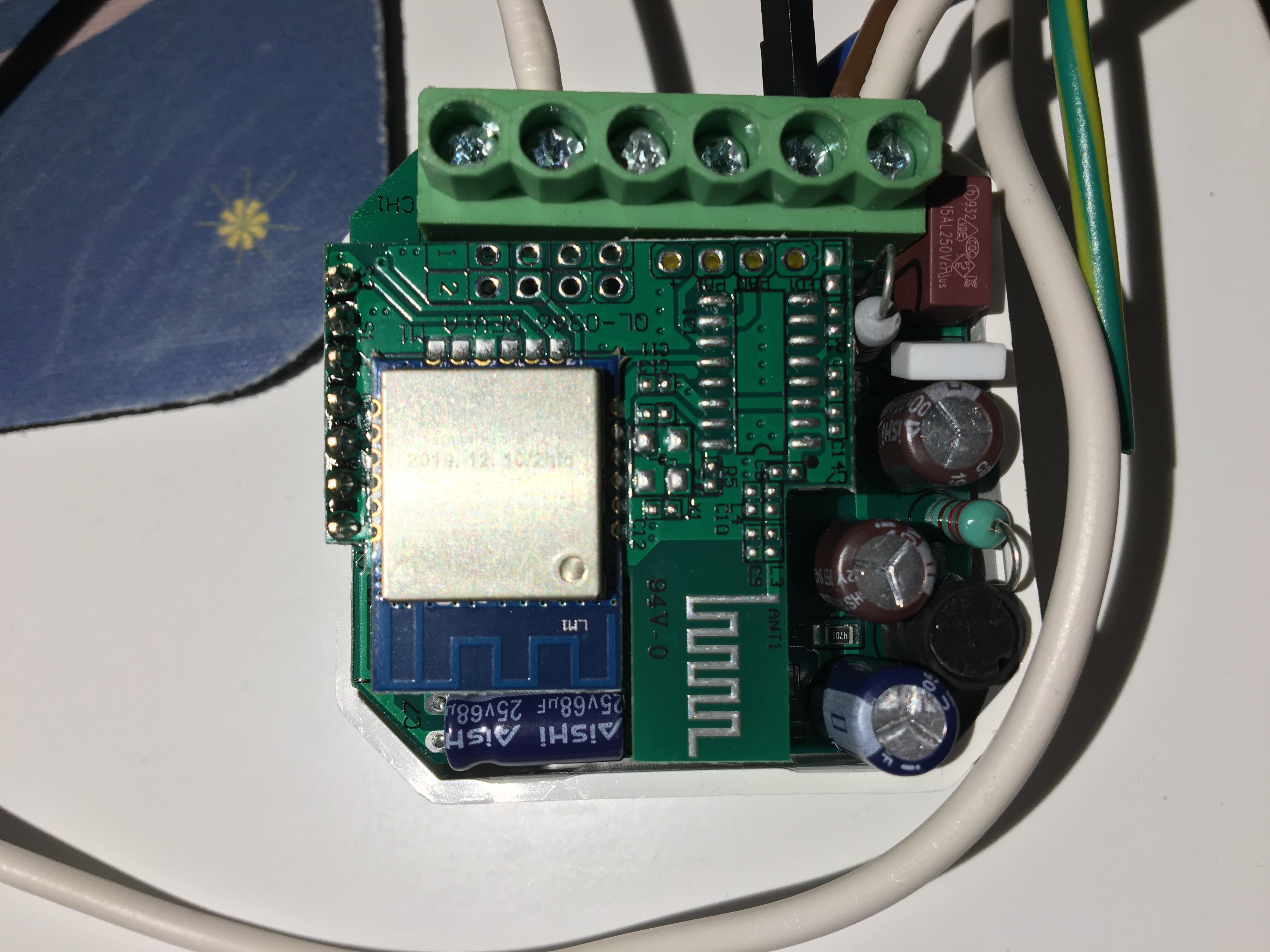
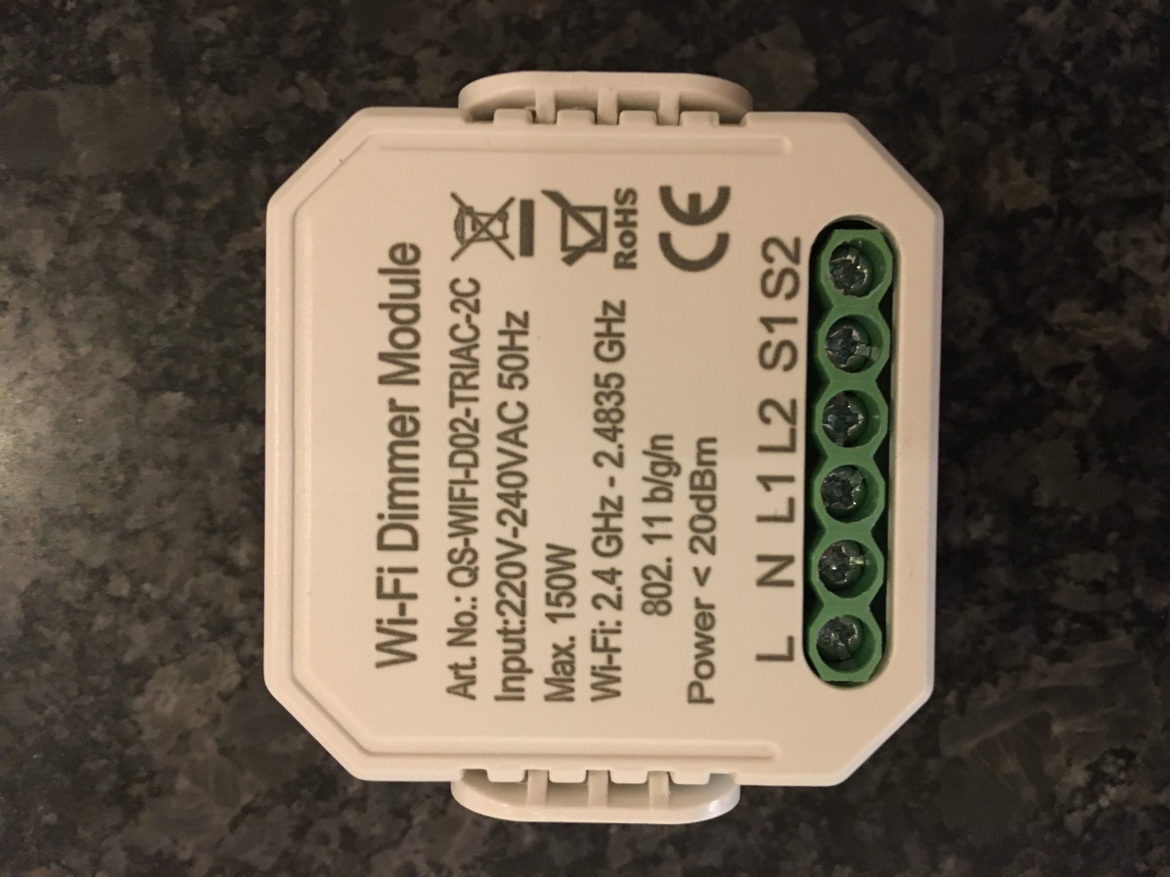
I didnt have the time to flash it with tasmota yet. Will try it this afternoon if I have the time.
 ressof
on 29 Jan 2020
ressof
on 29 Jan 2020
@ressof Please show your template and script when you have time
helio58
on 29 Jan 2020
@ressof Please show your template and script when you have time
I don't have any template or script.
ressof
on 29 Jan 2020
@ressof
Share your findings :)
helio58
on 29 Jan 2020
I manage to get it back. I did a power cycle. take a look in the wiki. Power cycle 4 times.
@helio58 Thanks for the link but it hasn't come back. I guess I got myself a mini brick.
I'll buy another one and give another try. I understand the script and I believe I could adapt it to support two channels (maximum scripting length allowing)
@ressof let us know of any progress.
lutierigb
on 29 Jan 2020
@lutierigb I bought 3 dimmers 1 gang.
2 work well. The third does not work and blows the fuses.
Just send a video to Bangood .
helio58
on 29 Jan 2020
Im working on a script that is working with two dimmers.
But its the first time writing script for Tasmota.
What does "sld1=Dimmer" do? Is Dimmer refering to the WebUi slider? and the PWM1?
What is the reference to PWM2?
This is what I got so far
>D
sw1=0
sw2=0
pw=0
cnt=0
tmr1=0
tmr2=0
hld1=0
hld2=0
tgl1=0
tgl2=0
sld1=0
sld2=0
dcmd=""
shtpl=2
shtpu=10
dd1=0
dd2=0
dmp=2.2
dsp=2
dll=15
dul=95
dv1=70
dv2=70

>B
=>Counter1 0
=>Counter2 0
=>Baudrate 9600
=#sd1(0)
=#sd2(0)

>F
cnt1=pc[1]
cnt2=pc[2]
if chg[cnt1]>0
then sw1=1
else sw1=0
endif
if chg[cnt2]>0
then sw2=1
else sw2=0
endif

tmr1+=1
tmr2+=1

if sw1==0
and tmr1>shtpl
and tmr1<shtpu
then
tgl1^=1
if tgl1==1
then
=#sd1(dv1)
else
=#sd1(0)
endif
endif

if sw2==0
and tmr2>shtpl
and tmr2<shtpu
then
tgl2^=1
if tgl2==1
then
=#sd2(dv2)
else
=#sd2(0)
endif
endif

if sw1>0
then
if hld1==0
then
dd1^=1
endif
if tmr1>shtpu
then
hld1=1
if tgl1>0
then
if dd1>0
then
dv1+=dsp
if dv1>dul
then
dv1=dul
endif
=#sd1(dv1)
else
dv1-=dsp
if dv1<dll
then
dv1=dll
endif
=#sd1(dv1)
endif
endif
endif
else
tmr1=0
hld1=0
endif

if sw2>0
then
if hld2==0
then
dd2^=1
endif
if tmr2>shtpu
then
hld2=1
if tgl2>0
then
if dd2>0
then
dv2+=dsp
if dv2>dul
then
dv2=dul
endif
=#sd2(dv2)
else
dv2-=dsp
if dv2<dll
then
dv2=dll
endif
=#sd2(dv2)
endif
endif
endif
else
tmr2=0
hld2=0
endif

>E
sld1=Dimmer
if chg[sld1]>0
then
if sld1>0
then
dv1=sld1
else
tgl1=0
endif
endif

sld2=Dimmer
if chg[sld2]>0
then
if sld2>0
then
dv2=sld2
else
tgl2=0
endif
endif

if pwr[1]==1
then
tgl1=1
=#sd1(dv1)
else
tgl1=0
=#sd1(0)
endif

if pwr[2]==1
then
tgl2=1
=#sd2(dv2)
else
tgl2=0
=#sd2(0)
endif

#sd1(pw)
dcmd="FF5501"+hn(pw*dmp)+"3005DC0A"
=>SerialSend5 %dcmd%
=>Dimmer %pw%
#

#sd2(pw)
dcmd="FF5502"+hn(pw*dmp)+"3005DC0A"
=>SerialSend5 %dcmd%
=>Dimmer %pw%
#
But its to long.
Can you pass two parameters to one sub?
ressof
on 30 Jan 2020
@ressof
Hi, plz give it a try (with SetOption68 1):
WiFi-2way-Dimmer-QS-WiFi-D02-Script.txt
I don't have a QS-WiFi-D02 2-way dimmer for testing.
Yes, "=Dimmer" refers to the WebUI slider and PWM1.
Could you please tell us the GPIOs for Counter1 and 2,
so we can add a template.
thxthx0
on 31 Jan 2020
@ressof
Hi, plz give it a try (with
SetOption68 1):
WiFi-2way-Dimmer-QS-WiFi-D02-Script.txtI don't have a QS-WiFi-D02 2-way dimmer for testing.
Yes, "=Dimmer" refers to the WebUI slider and PWM1.
Could you please tell us the GPIOs for Counter1 and 2,
so we can add a template.
I have one of these on the way and if it works well, I'll buy more. Would really love Tasmota support for it. Absolute cheapest way to dim two lights.
 bigrizzo
on 31 Jan 2020
bigrizzo
on 31 Jan 2020
@bigrizzo
Since these dimmers use frequency modulation to sense inputs, the scripting is required for these special devices. Key scripting features (e.g., fast polling >F) were developed to support these devices. Thus, Tasmota does support for these devices... as evidenced that users are using Tasmota and scripting for complete functionality. This type of "special" setup is not different than many other devices that require specific settings (SetOptions, etc.) as well as Rules for complete setup. It is the nature of the industry that new devices are constantly coming to market and thus requires additional investigation and configuration "discovery" in order to get a new device to be fully operational.
meingraham
on 31 Jan 2020
@ascillato2
Are there any plans for adding a version with scripting enabled to the auto builds on https://thehackbox.org/tasmota/
?
MortenVinding
on 31 Jan 2020
@MortenVinding
Perhaps you can make your case to @andrethomas. Or slip him enough benjamins ;-)
meingraham
on 31 Jan 2020
You mean as a variant or just with a custom my_user_config.h as we do with the wifiman binary?
 andrethomas
on 31 Jan 2020
andrethomas
on 31 Jan 2020
take into account that these inwall dimmers that require scripting are amongst the most visited pages on templates repo
blakadder
on 31 Jan 2020
@blakadder, In that case, it may be of interest if @arendst agrees to a new variant which is minimalized specifically for in-wall switches with added scripter support - This may also bring the binary size for such devices down significantly since it will never need any of the other drivers found in tasmota.bin
andrethomas
on 31 Jan 2020
I've been building my own on gitpod - it is true that for these switches, a
vast number of drivers can be excluded - which also leaves space to enable
TLS support for MQTT if that is something that worries you
On Fri, Jan 31, 2020 at 5:19 PM Andre Thomas notifications@github.com
wrote:
@blakadder https://github.com/blakadder, In that case, it may be of
interest if @arendst https://github.com/arendst agrees to a new variant
which is minimalized specifically for in-wall switches with added scripter
support - This may also bring the binary size for such devices down
significantly since it will never need any of the other drivers found in
tasmota.bin—
You are receiving this because you were mentioned.
Reply to this email directly, view it on GitHub
https://github.com/arendst/Tasmota/issues/5737?email_source=notifications&email_token=AABFQ4YC5SZ73322JE7ZYRTRARMSXA5CNFSM4HJ42QK2YY3PNVWWK3TUL52HS4DFVREXG43VMVBW63LNMVXHJKTDN5WW2ZLOORPWSZGOEKPLLXY#issuecomment-580826591,
or unsubscribe
https://github.com/notifications/unsubscribe-auth/AABFQ4ZYLIQ3HWY4OD7Z4YDRARMSXANCNFSM4HJ42QKQ
.
dbrb2
on 31 Jan 2020
if its a switch you don't need any sensor drivers or ir/rf stuff
@andrethomas probably, i just had no skin in the game so didn't think much of it. but that also draws the question of a shutters build 🌵
blakadder
on 31 Jan 2020
@blakadder yeah, or a combined one for things that don't need sensors... tasmota-nosensors.bin @arendst ? ;)
andrethomas
on 31 Jan 2020
I have got some information from this dimmer: QS-WIFI-D02_TRIAC-2C
It seems to be very similar to the one above but with the capability to dim two lights.The serial communication with STM8S003F3 has two more bytes
ff 55 01 1c 30 05 dc 0a
3rd byte dimmer 01 or 02
4th byte dim level 00 off, ff full on
the other bytes is the same as for the single dimmer.I didnt have the time to flash it with tasmota yet. Will try it this afternoon if I have the time.
I have tasmota running on it but cannot control second channel. Don't know if my dimmer is broken or the serial command is incorrect. Channel 1 works fine though. Can you re-check ?
EDIT:
GPIO13 is counter 1 and GPIO05 is counter 2
Any thing I send to 3rd byte 02 , second channel goes to around 100Volts and freezes there.
Any thing I send to 3rd byte 01 , first channel works fine.
Using WiFi-2way-Dimmer-QS-WiFi-D02-Script.txt channel 1 do up and down with switch also,
Channel 2 is not working correctly. I don't thing my unity is busted because on first boot without scripts enabled , both channels startup at around 60v, only channel 2 reacts badly to serial command. The unity seams to literally have 2 ST mcu soldered on the back of the esp lm1 pcb.
Since I did tuya-convert using a live xubuntu and since then rebooted, I don't have the backup of original FW.. arrgghh just to be sure my unit is not busted but I could swear I measure both channels going up and down with original fw though :S I'm hopping the serial hex string is missing something
 adfolfotregosa
on 3 Feb 2020
adfolfotregosa
on 3 Feb 2020
I have the same problem with second channel, but I found a solution.
1st channel use the 4th byte for dimm value
2nd channel use th 5th byte for dimm value
sd1(x)
di="FF5501"+hn(x*mp)+"0000000A"
=>SerialSend5 %di%
=>Channel1 %x%
sd2(x)
di="FF550200"+hn(x*mp)+"00000A"
=>SerialSend5 %di%
=>Channel2 %x%
#
 MaWork77
on 4 Feb 2020
MaWork77
on 4 Feb 2020
Could you guys also share the GPIOs?
lutierigb
on 4 Feb 2020
@ressof
Hi, plz give it a try (with
SetOption68 1):
WiFi-2way-Dimmer-QS-WiFi-D02-Script.txtI don't have a QS-WiFi-D02 2-way dimmer for testing.
Yes, "=Dimmer" refers to the WebUI slider and PWM1.
Could you please tell us the GPIOs for Counter1 and 2,
so we can add a template.
Just in case you didn't see @adfolfotregosa post below with the GPIOs as follows.
GPIO13 is counter 1 and GPIO05 is counter 2
bigrizzo
on 4 Feb 2020
Template:
{"NAME":"MS-105","GPIO":[255,107,255,255,38,43,255,255,37,42,255,255,255],"FLAG":0,"BASE":54}
Script:
script.txt
Console:
SetOption68 1
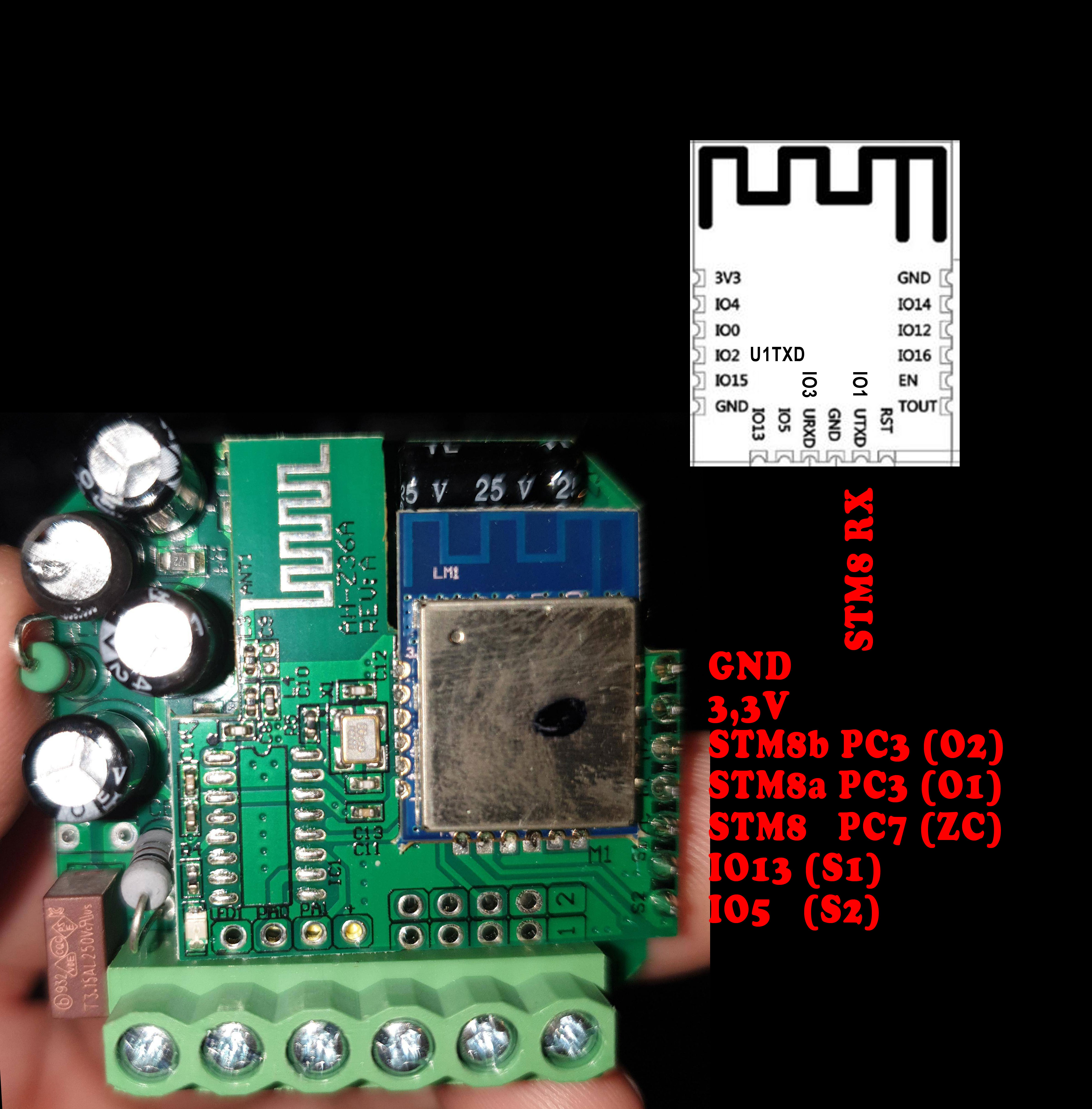
MaWork77
on 4 Feb 2020
Serial communication:
Byte 1+2: Header (FF55)
Byte 3 : Channel 1 (01) or Channel 2 (02)
Byte 4 : Dim Value Channel 1
Byte 5 : Dim Value Channel 2
Byte 6+7 : looks like a Delay Value for Fade (0000 -> hard, FFFF -> smoother)
Byte 8 : End (0A)
MaWork77
on 4 Feb 2020
Serial communication:
Byte 1+2: Header (FF55)
Byte 3 : Channel 1 (01) or Channel 2 (02)
Byte 4 : Dim Value Channel 1
Byte 5 : Dim Value Channel 2
Byte 6+7 : looks like a Delay Value for Fade (0000 -> hard, FFFF -> smoother)
Byte 8 : End (0A)
Yes, good find, very nice !
The script is not perfect yet, unfortunately, I can make it screw up when messing with the controls.
adfolfotregosa
on 4 Feb 2020
Thank for the script and correct serial communication.
Been on vacation so I have been able to try this until now.
I have on thing that doesnt work. The connection between Domoticz and Tasmota.
Tasmota always send 100 stregth to Domoticz by MQTT even if the slider is almost the lowest.
Do you know how to fix this?
ressof
on 4 Feb 2020
hello, i also have 2gang dimmer so i wanna ask if i have to convert to tasmota? Is it working?
 Bajger-M
on 8 Feb 2020
Bajger-M
on 8 Feb 2020
hello, i also have 2gang dimmer so i wanna ask if i have to convert to tasmota? Is it working?
Not exactly sure what you're asking. You can use the Tuya app with this. Use Tasmota only if you know what you are doing. By your question, you might be better off just using the Tuya app.
bigrizzo
on 9 Feb 2020
I have a Home assistant and I would like to integrate it into it, I have experience with tasmota, just wondering if the original is better or tasmota. Tuya have a problem with integration and there will probably be more time lag.
Bajger-M
on 9 Feb 2020
I have a number of Sonoff devices installed around the house running Tasmota. Two of these dual dimming modules have now arrived and I would love to begin catching up with you all. Would someone patient kindly summarise the amazing work done thus far into a mini-tutorial?
I would be able to flash Tasmota onto the device using the pinout posted above, but thereafter I would be lost --- how, for instance, are the scripts applied/used?
 doceave
on 9 Feb 2020
doceave
on 9 Feb 2020
Upload tasmota via tyua convertor I can handle, but set it to work dimmer. After inserting the script, the dimmer works fine? Or is the original better?
Bajger-M
on 9 Feb 2020
how is it now dad when there are no buttons in the tasmota?
Bajger-M
on 13 Feb 2020
How do you power cycle this dimmer switch? just on and off 4 times in quick
succession?
On Sun, Jan 26, 2020 at 2:26 PM Jose notifications@github.com wrote:
@lutierigb https://github.com/lutierigb I have problem at once with a
sonoff mini.
I manage to get it back. I did a power cycle. take a look in the wiki.
Power cycle 4 times.
https://github.com/arendst/Tasmota/wiki/Device-Operational-Recovery—
You are receiving this because you were mentioned.
Reply to this email directly, view it on GitHub
https://github.com/arendst/Tasmota/issues/5737?email_source=notifications&email_token=ALLKNQS7RZUAH2UEB5FDXH3Q7UUKZA5CNFSM4HJ42QK2YY3PNVWWK3TUL52HS4DFVREXG43VMVBW63LNMVXHJKTDN5WW2ZLOORPWSZGOEJ5MVZY#issuecomment-578472679,
or unsubscribe
https://github.com/notifications/unsubscribe-auth/ALLKNQXZIR6G7STHE626U4DQ7UUKZANCNFSM4HJ42QKQ
.
epicurean70
on 14 Feb 2020
when I turn on the 1st gang and then the 2nd gang, the lights will go to maximum luminosity. and you cannot turn off the 1st gang until I turn off the 2nd gang. Or if I turn on first 2.gang so you can not turn on 1.gang
Bajger-M
on 16 Feb 2020
I uploaded the tasmota. How to upload a script?
 aldii-hassio
on 22 Mar 2020
aldii-hassio
on 22 Mar 2020
You can find a modified version of the script which is intend to work with SetOption20 1 in order to have Channel
It has been working fine for about 2 months now.
Credits to thxthx0 and MaWork77, this script is based on their version.
In the repo README I have also summarize some info to properly set up the device.
 mick96
on 16 May 2020
mick96
on 16 May 2020
I just received a "2 gang wifi dimmer" (link).
Externally it looks identical to other dimmers but from the insides i looks different, so i'm not really sure if i could also use the script on this devices. Has someone already get it running on this devices? It's a TYWE2S (esp8285) chip.
Another question: i tried getting the device in ez-mode by turning s1 off and then pressing it for 10 seconds but without success. Sometimes the device will bleep once after 5 seconds of holding the button down, but it won't go in EZ-mode where is will bleep continuously.
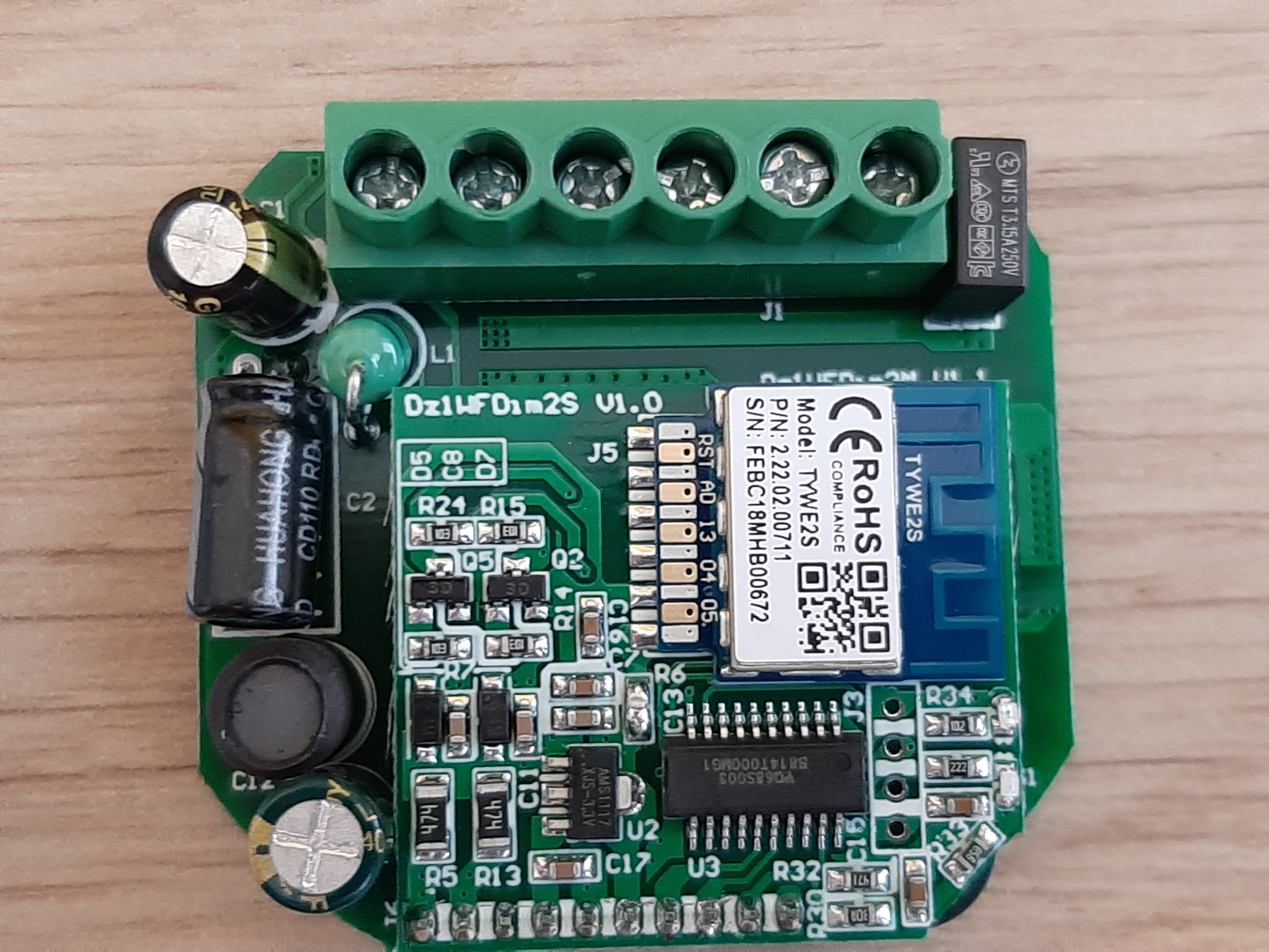
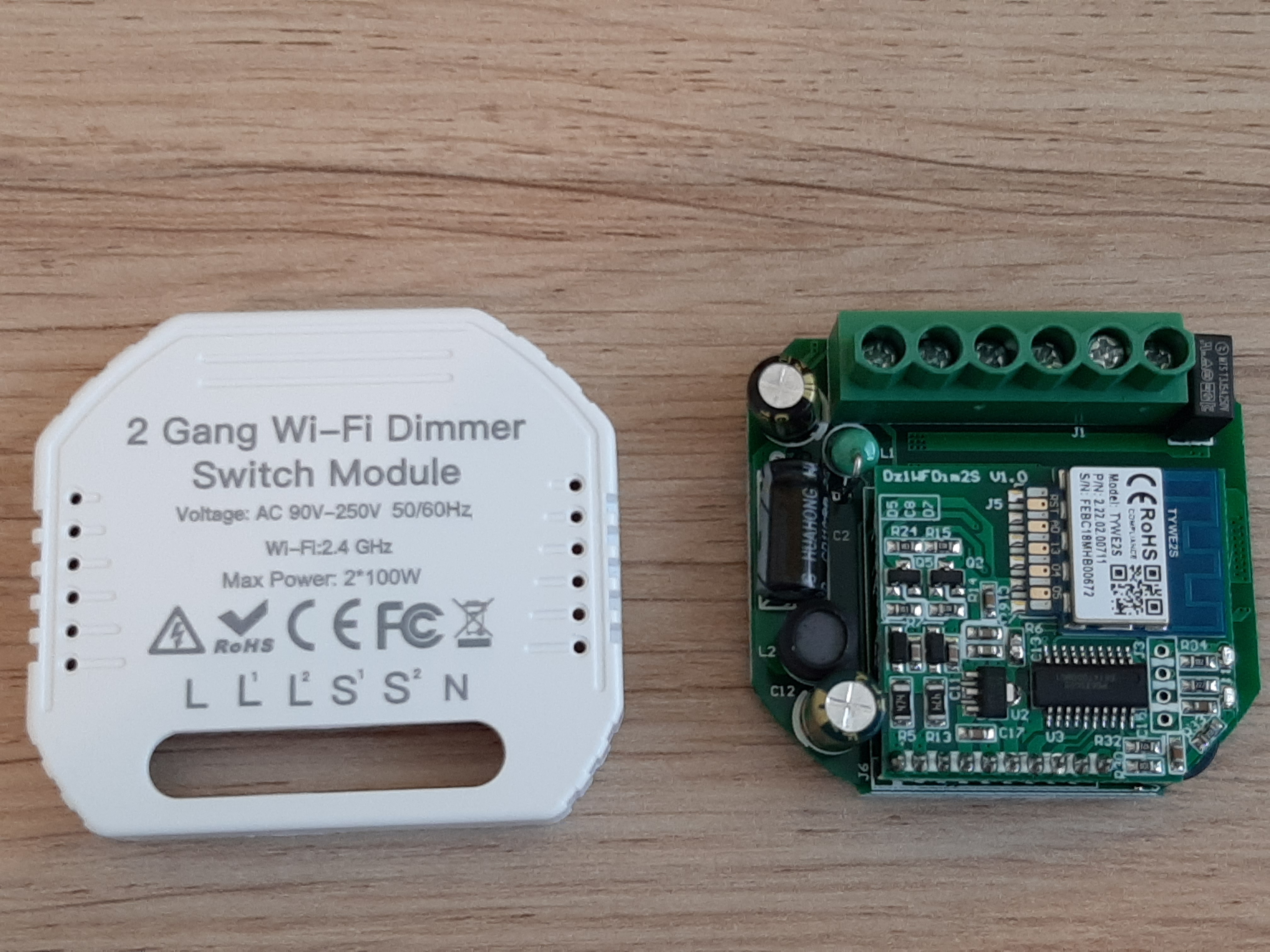
 LukevdPalen
on 18 May 2020
LukevdPalen
on 18 May 2020
Yes I just got my hand on this new version of the 2 gang dimmer. It has only one
MCU (mine has a HT66F019) so I'm pretty sure the script won't work on it. Unfortunately I can't work on it because it is not mine so I cannot risk to screw it up. My hope is that it uses the standard TuyaMCU Serial interface making the reverse engineering process easier.
@LukevdPalen Try to press the SW1 repeatedly for 10 times after having power it on. Not too fast or it won't work.
mick96
on 18 May 2020
@mick96 i successfully got the device in EZ-mode! Sadly enough the Tuya convert procedure doesn't work, I think due to a new PSK format https://github.com/ct-Open-Source/tuya-convert/issues/483. I think there is nothing more to due than get my soldering iron out to make a dump of the original firmware and start debugging.
LukevdPalen
on 19 May 2020
Ok, then if u have the possibility it would be nice to sniff serial communication between the MCU and ESP while running OFW.
I'm available to support you with the script if needed
mick96
on 19 May 2020
@mick96 it would be very helpful if you could point me in the right direction. I have no further experience with sniffing serial communications until now.
LukevdPalen
on 19 May 2020
To be honest, I never done it on this kind of device. But I would try to connect a serial to USB converter (e.g FTTDI rs232) and attach RX of your adapter to TX on the ESP (according to datasheet the pinout should be as in pictures). At this point you can try configure your serial device at 9600,n,8,1 using a console like PuTTY and see if you receive something. If this works you can try to connect on RX and you should see the MCU speaking to the ESP, providing that the communication is bidirectional that it is not the case in the old 2 gang dimmer.
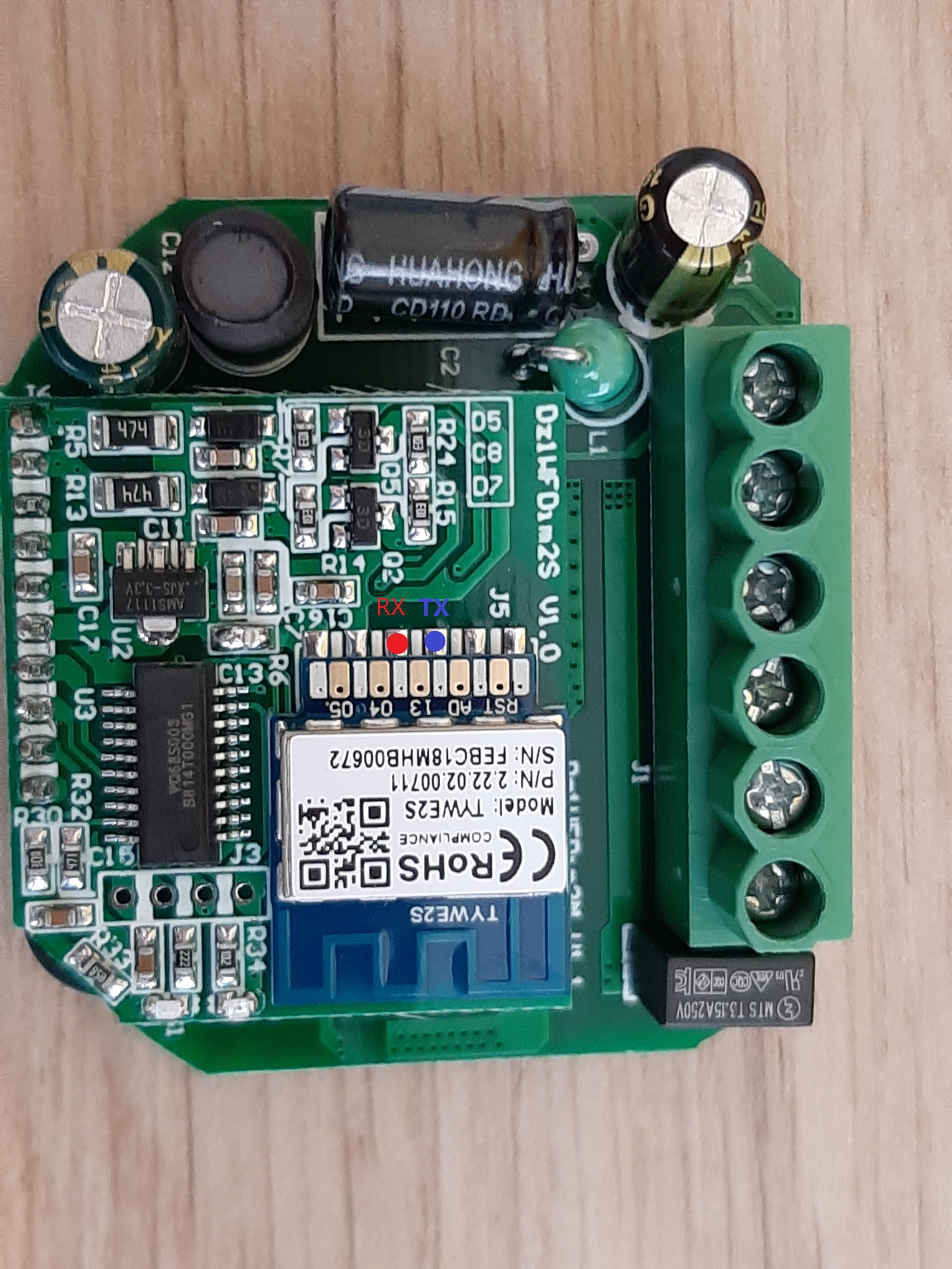
Hopefully someone more expert can guide you better.
Good luck
mick96
on 21 May 2020
I managed to sniff some serial communications by using the physical buttons
1 ON    55 aa 00 07 00 05 01 01 00 01 01 0f 55 aa 00 07 00 08 02 02 00 04 00 00 01 41 58
1 OFF   55 aa 00 07 00 05 01 01 00 01 00 0e 55 aa 00 07 00 08 02 02 00 04 00 00 01 41 58

2 ON    55 aa 00 07 00 05 07 01 00 01 01 15 55 aa 00 07 00 08 08 02 00 04 00 00 01 7e 9b
2 OFF   55 aa 00 07 00 05 07 01 00 01 00 14 55 aa 00 07 00 08 08 02 00 04 00 00 01 7e 9b
Somehow i have some difficulties to backup the firmware, I removed the shield and tried to connect ground to the gpio0 pin (on the chip) but without any luck, esptool won't recognize the chip
LukevdPalen
on 22 May 2020
Good job, it seems the it uses the standard Tuya MCU protocol and you are reading the MCU which notify the ESP of the changes (command word=07).
dpID:
-0x01: 1st switch (boolean)
-0x07: 2nd switch (boolean)
-0x02: probably 1st Dimmer value
-0x08: probably 2nd Dimmer value
Now you can try to send some command to the MCU using command word 0x06 and also listen to what the ESP is sending when controlled from wifi.
If you try to flash it without desoldering the TYWE2S you might encounter problems as it uses the same serial that is connected to the MCU. You can try and look for the Chip Enable pin on the MCU chip, pulling it down and see if the ESP gets recognized.
Before try everything, did you switch the connection after having sniff the serial and try to flash with ESPtool?
mick96
on 23 May 2020
How to desolder the TYWE2S from that new module?
 blackscreener
on 27 May 2020
blackscreener
on 27 May 2020
@mick96 sorry for my late reply I didn't manage to extract the firmware jet. But this weekend I installed the TUYA app and did some further serial sniffing. This is what I could intercept. I couldn't find a pattern in the dimming function command, maybe someone can help me with that?
|ACTION |Frame Header|Version|Command Word|Data Length|dpID|Data Type|Function Length|Function Command|Verification Method|
|--------|------------|-------|------------|-----------|----|---------|---------------|----------------|-------------------|
|1 ON |55aa |00 |06 |0005 |01 |01 |0001 |01 |0e |
|1 OFF |55aa |00 |06 |0005 |01 |01 |0001 |00 |0d |
|1 dim10 |55aa |00 |06 |0008 |02 |02 |0004 |00000065 |7a |
|1 dim20 |55aa |00 |06 |0008 |02 |02 |0004 |000000c3 |d8 |
|1 dim30 |55aa |00 |06 |0008 |02 |02 |0004 |00000127 |3d |
|1 dim40 |55aa |00 |06 |0008 |02 |02 |0004 |0000018b |a1 |
|1 dim50 |55aa |00 |06 |0008 |02 |02 |0004 |000001ef |05 |
|1 dim60 |55aa |00 |06 |0008 |02 |02 |0004 |0000025b |72 |
|1 dim70 |55aa |00 |06 |0008 |02 |02 |0004 |000002be |d5 |
|1 dim80 |55aa |00 |06 |0008 |02 |02 |0004 |0000031d |35 |
|1 dim90 |55aa |00 |06 |0008 |02 |02 |0004 |00000381 |99 |
|1 dim100|55aa |00 |06 |0008 |02 |02 |0004 |000003e8 |00 |
|2 ON |55aa |00 |06 |0005 |07 |01 |0001 |01 |14 |
|2 OFF |55aa |00 |06 |0005 |07 |01 |0001 |00 |13 |
|2 dim10 |55aa |00 |06 |0008 |08 |02 |0004 |00000061 |7c |
|2 dim20 |55aa |00 |06 |0008 |08 |02 |0004 |000000c3 |de |
|2 dim30 |55aa |00 |06 |0008 |08 |02 |0004 |00000129 |45 |
|2 dim40 |55aa |00 |06 |0008 |08 |02 |0004 |0000018d |a9 |
|2 dim50 |55aa |00 |06 |0008 |08 |02 |0004 |000001ef |0b |
|2 dim60 |55aa |00 |06 |0008 |08 |02 |0004 |00000254 |71 |
|2 dim70 |55aa |00 |06 |0008 |08 |02 |0004 |000002b9 |d6 |
|2 dim80 |55aa |00 |06 |0008 |08 |02 |0004 |0000031e |3c |
|2 dim90 |55aa |00 |06 |0008 |08 |02 |0004 |00000380 |9e |
|2 dim100|55aa |00 |06 |0008 |08 |02 |0004 |000003e8 |06 |
update: it seems to be normal dimming TUYA command as described over here:
https://tasmota.github.io/docs/TuyaMCU/#dimmers
One other thing that facing is that it's nearly impossible to de-solder the ESP. I think the pinout of the MCU on the dimmer is the same as those of the HT66F019, do you have a clue which pin cloud be the "chip enable" pin? Otherwise, we will have to wait until the PSK issue is resolved
LukevdPalen
on 2 Jun 2020
Amazing work man, now we know that it is using standard tuya interface for sure. Tasmota has tuyaMCU module which is perfect for controlling the MCU but it seems it can map only one dimmer. It might be possible to do some "dirty" implementation through script but it would be way better if in future release tasmota will support multiple dimmer. I'm a newbie of tasmota code therefore I have no idea where we need to work in order to add this features in the code.
Regarding flashing the chip I skimmed through the datasheet of the MCU and this one apparently does not have a chip enable or reset pin. Have you check if the esp and MCU are directly connected or maybe there is a resistor in between that can be removed? You can also check where the 4 pads (the one next to the MCU) lead to. My guess is that the vendor used it to flash the MCU or ESP and if we are lucky one of them is used to disable the MCU.
mick96
on 2 Jun 2020
How to desolder the TYWE2S from that new module?
You don't have to desolder the ESP module. I discovered that next to the VCC pin of the ESP module there is a soldered "bridge" that connects the MCU and the ESP module. If you remove the solder over there than the mcu won't be powered up and you than can program the esp by removing the shield and pulling down the GPIO0 pin.

LukevdPalen
on 3 Jun 2020
How to desolder the TYWE2S from that new module?
You don't have to desolder the ESP module. I discovered that next to the VCC pin of the ESP module there is a soldered "bridge" that connects the MCU and the ESP module. If you remove the solder over there than the mcu won't be powered up and you than can program the esp by removing the shield and pulling down the GPIO0 pin.
Thank you very much. How to remove the shield?
blackscreener
on 3 Jun 2020
With this script running, is it still possible to reset the device with
various combinations long presses...?
On Wed, Jun 3, 2020 at 4:23 PM blackscreener notifications@github.com
wrote:
How to desolder the TYWE2S from that new module?
You don't have to desolder the ESP module. I discovered that next to the
VCC pin of the ESP module there is a soldered "bridge" that connects the
MCU and the ESP module. If you remove the solder over there than the mcu
won't be powered up and you than can program the esp by removing the shield
and pulling down the GPIO0 pin.[image: 20200518_173412]
https://user-images.githubusercontent.com/1506262/83654731-c8885000-a5bd-11ea-8241-11faee596601.jpgThank you very much. How to remove the shield?
—
You are receiving this because you were mentioned.
Reply to this email directly, view it on GitHub
https://github.com/arendst/Tasmota/issues/5737#issuecomment-638269053,
or unsubscribe
https://github.com/notifications/unsubscribe-auth/AABFQ4Y7IQV3L7VRP5YYSCLRUZTIDANCNFSM4HJ42QKQ
.
dbrb2
on 3 Jun 2020
Flashed with tasmota standard, one channel is working like a charm. DimmerRange is 0 - 1003.
blackscreener
on 3 Jun 2020
@blackscreener nice, i also managed to flash the device. Can you share your configuration? What template did you use?
LukevdPalen
on 3 Jun 2020
@blackscreener nice, i also managed to flash the device. Can you share your configuration? What template did you use?
Template: TuyaMCU (54)
Initial config: https://tasmota.github.io/docs/TuyaMCU/#dimmers
21:32:36 RSL: stat/tasmota_57CA8B/RESULT = {"TuyaMCU":[{"fnId":11,"dpId":1},{"fnId":21,"dpId":2},{"fnId":12,"dpId":7}]}
dpID 1 - on, off 1 ch
dpID 2 - dimmer 1 ch
dpID 7 - on, off 2 ch
dpID 8 - dimmer 2 ch
We need to add 2nd dimmer option to Tasmota.
blackscreener
on 3 Jun 2020
@blackscreener Thanks for sharing. Besides channel 2 being uncontrollable in Tasmota. I also notice that the dimming state is not being stored. When switching on and off the dimming level is at a very low value. Do you also have this issue?
LukevdPalen
on 6 Jun 2020
@LukevdPalen
For me dimming state is being stored. Try my config, second channel as relay is disabled.
Tuya_2_ch dimmer_config_tasmota_57CA8B_2699_8.3.1.2.zip
blackscreener
on 6 Jun 2020
@LukevdPalen
2 channel works in esphome without problems. Thank you very much for help.

blackscreener
on 9 Jun 2020
With this script running, is it still possible to reset the device with various combinations long presses...?
@dbrb2
No, reset mode is only for default wifi settings. If you want to change minimum brigtness value for MCU you must send TuyaSend command from Tasmota console:
https://github.com/arendst/Tasmota/issues/7379#issuecomment-576697518
blackscreener
on 9 Jun 2020
Hi, I have the same 2 gangs (TYWE2S one) but I'm still stuck at the flashing part.
- I tried to desolder it in order to access the IO0 pin at the back without success.
- I tried Tuya Converter but I got a device with a new PSK format
How did you manage to flash it ?
Thanks
 Clement87
on 27 Jun 2020
Clement87
on 27 Jun 2020
Programming it is not the issue. The issue is to know how to configure it with the two dimming channels.
The GPIO_0 is accessible after you remove the metal shield.

@blackscreener, what are the complete comand list to configure the two dimming channels? I tried to restore the configuration file you shared and I lost the comunication with the module, I needed to erase and program again the flash.
Thanks
 diasarmando
on 27 Jun 2020
diasarmando
on 27 Jun 2020
I just can configure as funcion two relay, just one dimmer.

Commands used:
TuyaMCU 21,2
TuyaMCU 11,1
TuyaMCU 12,7
I think is missing the implementation of the second dimmer on the tasmota and I'm guessing the command would be:
TuyaMCU 22,8
There is any other way?
diasarmando
on 27 Jun 2020
@diasarmando
https://github.com/arendst/Tasmota/issues/8663
I gave up with tasmota. With esphome 2 channels works fine.
blackscreener
on 27 Jun 2020
@blackscreener can you please share the link or configuration?
Thanks
diasarmando
on 28 Jun 2020
@diasarmando
esphome:
  name: 2ch_dimmer
  platform: ESP8266
  board: esp01_1m

wifi:
  ssid: "xxxxxxx"
  password: "xxxxxxxx"

  # Enable fallback hotspot (captive portal) in case wifi connection fails
  ap:
    ssid: "2Ch Dimmer"
    password: "xxxxxxx"

captive_portal:

# Make sure logging is not using the serial port
logger:
  baud_rate: 0

# Enable Home Assistant API
api:
  password: "xxxxxx"

ota:
  password: "xxxxxx"

sensor:
  - platform: wifi_signal
    name: "2CH Dimmer RSSI"
    update_interval: 60s

# My dimmer used the hardware serial port on the alternate pins
uart:
  rx_pin: GPIO3
  tx_pin: GPIO1
  baud_rate: 9600

# Register the Tuya MCU connection
tuya:

# Create a light using the dimmer
light:
  - platform: "tuya"
    name: "dim1"
    dimmer_datapoint: 2
    switch_datapoint: 1
    min_value: 0
    max_value: 1003

  - platform: "tuya"
    name: "dim2"
    dimmer_datapoint: 8
    switch_datapoint: 7
    min_value: 0
    max_value: 1003
Is that new MS-105B 1 ch dimmer or it's old V2 version ? I flashed it with tuya convert.


blackscreener
on 1 Jul 2020
You can find a modified version of the script which is intend to work with
SetOption20 1in order to have Channel and Power decoupled. In other word the brightness channel and power are separated, so you are able to change brightness before powering on the device. The script is also shorter giving the possibility to add further features.
It has been working fine for about 2 months now.Credits to thxthx0 and MaWork77, this script is based on their version.
In the repo README I have also summarize some info to properly set up the device.
Hello!!!! I did everything according instruction.I have entered the script, the template and activated "Setoption68 1". In web interface I see all correct. Toggle 1 and 2 are working but my lamps not light(((((( What is the problem???
 yuraivan
on 7 Jul 2020
yuraivan
on 7 Jul 2020
Hello, I have this device without dimmer, I need to use with two channels for rollershutter with Tasmota blind option,
I tried flashing with tuya-convert but withoutc succes, Could someone help me with the GPIO mapping? thanks


 gonzaechev
on 13 Jul 2020
gonzaechev
on 13 Jul 2020
@LukevdPalen how did you remove the shield?
 jayjohns0n
on 5 Nov 2020
jayjohns0n
on 5 Nov 2020
@LukevdPalen how did you remove the shield?
I used a hot air iron. I also tried to drill a hole carefully at the right place. Both worked.
Clement87
on 6 Nov 2020
Thank you @Clement87 I got a hot air iron and it worked well. Did you manage to flash it? I can't get it into flash mode, I connected GPIO0 with a needle to ground but I couldn't flash it. same method worked with my Sonoff devices with ESP8266. Did someone have the same problem?

jayjohns0n
on 15 Nov 2020
@jayjohns0n I flashed four of them without issue. Check your wires and set GPIO0 to the ground only a few seconds while you flash it.
Clement87
on 19 Nov 2020
Thank you @Clement87 I got a hot air iron and it worked well. Did you manage to flash it? I can't get it into flash mode, I connected GPIO0 with a needle to ground but I couldn't flash it. same method worked with my Sonoff devices with ESP8266. Did someone have the same problem?
Hi I have the same problem, i dont get if flashed, did all as per above
-removed the shield
- soldered the serial connection
- removed the bridge
- while plugging in my usb in the computer i jump between GPIO0 and earth
Issue i don't know if it's in flashing mode ...? Neither with Tasmota or ESPeasy the flashing starts
Any suggestions ...
 TheeBeginner
on 5 Dec 2020
TheeBeginner
on 5 Dec 2020
Thank you @Clement87 I got a hot air iron and it worked well. Did you manage to flash it? I can't get it into flash mode, I connected GPIO0 with a needle to ground but I couldn't flash it. same method worked with my Sonoff devices with ESP8266. Did someone have the same problem?
Hi I have the same problem, i dont get if flashed, did all as per above
-removed the shield
- soldered the serial connection
- removed the bridge
- while plugging in my usb in the computer i jump between GPIO0 and earth
Issue i don't know if it's in flashing mode ...? Neither with Tasmota or ESPeasy the flashing starts
Any suggestions ...
Hi,
- Be sure you didn't invert RX and TX (take a look at the datasheet)
- Be sure the bridge is properly desoldered (use a multimeter to check)
- Be sure you used a USB cable that can transfert datas (a lot of cable only charge devices)
- Use an other USB to Serial adapter (not sure, but as I remember, you need one with 3.3V, not 5V. This is something to check)
- For the flashing part, touch GPIO0 with ground then connect the USB cable then run the flash. When flashing is progressing you can take off GPIO0 needle.
I was using esphome python module.
That's all.
Clement87
on 11 Dec 2020
Thank you @Clement87 I got a hot air iron and it worked well. Did you manage to flash it? I can't get it into flash mode, I connected GPIO0 with a needle to ground but I couldn't flash it. same method worked with my Sonoff devices with ESP8266. Did someone have the same problem?
Hi I have the same problem, i dont get if flashed, did all as per above
-removed the shield
- soldered the serial connection
- removed the bridge
- while plugging in my usb in the computer i jump between GPIO0 and earth
Issue i don't know if it's in flashing mode ...? Neither with Tasmota or ESPeasy the flashing starts
Any suggestions ...Hi,
- Be sure you didn't invert RX and TX (take a look at the datasheet)
- Be sure the bridge is properly desoldered (use a multimeter to check)
- Be sure you used a USB cable that can transfert datas (a lot of cable only charge devices)
- Use an other USB to Serial adapter (not sure, but as I remember, you need one with 3.3V, not 5V. This is something to check)
- For the flashing part, touch GPIO0 with ground then connect the USB cable then run the flash. When flashing is progressing you can take off GPIO0 needle.
I was using esphome python module.
That's all.
Thanks for the reply, did all at least I think i did, with RX / TX you mean RX goes on TX and TX on RX ? I also tried via Tuyaconvert and a pi but did not succeed there neither although i could get it into the flashing mode like that some times.
Thanks
TheeBeginner
on 11 Dec 2020
Related issues
 he-so
·
3Comments
he-so
·
3Comments
 Vujagig
·
3Comments
Vujagig
·
3Comments
 ximonline
·
3Comments
ximonline
·
3Comments
 TylerDurden23
·
3Comments
TylerDurden23
·
3Comments
 abzman
·
3Comments
abzman
·
3Comments
Most helpful comment
Got my WiFi Dimmer today and flashed it successfully with Tasmota,
it's workin'...
I had to set pin RE (= STM8 MCU Pin4 NRST) to GND for backup and flash
(and also GPIO0 to GND for flash mode) - didn't try Tuya-Convert.
As DeanoXX already found out, there seems to be only one simple command
with dim level between 0 to 255 (00 = Off / FF = full on).
With Tasmota and SerialSend5 I can now adjust all brightness levels:
off 0% -> SerialSend5 FF 55 00 05 DC 0A
on 100% -> SerialSend5 FF 55 FF 05 DC 0A
0 - 100% -> SerialSend5 FF 55 xx 05 DC 0A
Push Button / Switch input 'S' is connected to GPIO13
I can control the dimmer module well with virtual relays and rules,
but the manual push switch isn't working reliably yet, it doesn't always respond (?),
and of course no 'Long Push' for dimming.