Hi,
It is not a new issue per say, but need guidance so that I can upload the firmware. On Sonoff POW v2.0, how do I bring the unit to firmware change mode. Instructions that I found on the internet for different variations does not seem to work. Anyone can point to an article or link that would help on POW is greatly appreciated. Also, how do I identify that sonoff is in upload mode (visually).
Thank you. Apologies for putting this question in this forum.
Raj
 rajkedda
All 55 comments
Can you take a picture of the board?
 gajotnt
on 17 Nov 2017
gajotnt
on 17 Nov 2017
Hi,
Please the top view and pcb board side view.


rajkedda
on 17 Nov 2017
They really fill those tracks with tin now eheheh
Ok, connect the GPIO 0 to ground, try keeping it always connected until flash is done.

Hope it works
gajotnt
on 17 Nov 2017
Thank you for prompt response. Can you point out which one is GPIO0 and GND(which one to connect)
rajkedda
on 17 Nov 2017
Either one of the red circles is gpio 0. And ground is GND (bellow TX)
gajotnt
on 17 Nov 2017
Cool will try now
rajkedda
on 17 Nov 2017
I connected the two(GPIO0 and GND) for 2 secs and connected the power to FTDI. POW did not have any lights blinking (blue or red). Launched Ardiuno and tried upload the sketch. It gave me this error message:
Arduino: 1.8.5 (Windows 10), Board: "Generic ESP8266 Module, Serial, 80 MHz, 40MHz, DOUT, 115200, 1M (64K SPIFFS), ck, Disabled, None"
Archiving built core (caching) in: ..\AppData\Local\Temparduino_cache_173509\core\core_esp8266_esp8266_generic_UploadTool_esptool,CpuFrequency_80,FlashFreq_40,FlashMode_dout,UploadSpeed_115200,FlashSize_1M64,ResetMethod_ck,Debug_Disabled,DebugLevel_None_____28017859ea84c51dcfdb6c0670d2f894.a
Sketch uses 480644 bytes (50%) of program storage space. Maximum is 958448 bytes.
Global variables use 45472 bytes (55%) of dynamic memory, leaving 36448 bytes for local variables. Maximum is 81920 bytes.
warning: espcomm_sync failed
error: espcomm_open failed
error: espcomm_upload_mem failed
error: espcomm_upload_mem failed
This report would have more information with
"Show verbose output during compilation"
option enabled in File -> Preferences.
rajkedda
on 17 Nov 2017
Are connecting the FTDI correctly?
Try keeping the gpio always grounded while connected to the ftdi
gajotnt
on 17 Nov 2017
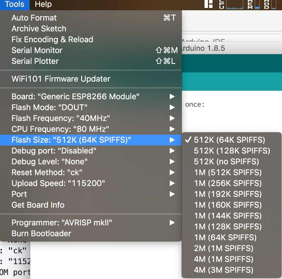
And use another linker file (1M no spiffs).
 arendst
on 17 Nov 2017
arendst
on 17 Nov 2017
Thank you. I had to hold it a sec longer than before to get it to load the flash. It loaded successfully with the 1M 64K spiffs, should I reupload with 1M no spiffs? For normal operation, should I put the unit on 5V to work or 3.3V is good. I unplugged the FTDI and replugged it back in. As I dont see any light flashing after the upload is done.
rajkedda
on 17 Nov 2017
If you want to be able to use OTA you will need to re-flash with the correct linker being 1M no spiffs.
Do not use 5V.
Do not use the FTDI when AC power is connected.
For now remove and reconnect the FTDI and configure via serial your Pow.
arendst
on 17 Nov 2017
On the webpage of the sonoff, it reads as Sonoff Basic vs POW. Did I upload the wrong bin file?
rajkedda
on 17 Nov 2017
No, no, no. Just select the correct module via the webpage and get to know the commands in the wiki.
arendst
on 17 Nov 2017
Thank you for help, was able to successfully do the flash update. I want to add an external switch to this unit, can you share which pins I need to solder so that I can connect a momentary push button and also if there is a 5v tap on this board. I wish there was documentation for this board.
rajkedda
on 10 Dec 2017
Its not recommended to plug anything to the POW...
Special Pow Attention ⚠️️
Do not connect AC power and the serial connection at the same time The Gnd connection of the Pow has a 50% chance of being connected to the live AC wire. Connecting serial with your PC will fry your PC.
Also do not connect any additional sensors to serial pins until you are 100% sure. It can at least destroy your Pow!
The GPIOs on the Pow might be connected to AC power, therefore it is not possible to add sensors to the Pow.
gajotnt
on 10 Dec 2017
Thank you. I saw folks connect an external button to Sonoff Basic to GPIO 14 and GND etc. I thought this may have it as well. This is one of the how-to, I saw on internet post, http://www.sigmdel.ca/michel/ha/domo/domo_07_en.html
rajkedda
on 10 Dec 2017
You can, but on the POW its not recommended... use at your own risk...
gajotnt
on 11 Dec 2017
Thank you. If it is risky, then I will skip on the POW and do it in Basic as others have done.
rajkedda
on 11 Dec 2017
Hello Everyone iam having the same problem.
Can some one please help me with flashing .
I tried the all the steps given above but still no luck
Arduino: 1.8.5 (Windows 10), Board: "Generic ESP8266 Module, 80 MHz, 40MHz, DOUT, 115200, 1M (64K SPIFFS), ck, Disabled, None"
Archiving built core (caching) in: C:\Users\SEETEN~1\AppData\Local\Temparduino_cache_709758\core\core_esp8266_esp8266_generic_CpuFrequency_80,FlashFreq_40,FlashMode_dout,UploadSpeed_115200,FlashSize_1M64,ResetMethod_ck,Debug_Disabled,DebugLevel_None_____a14c13a6526d97249f4a56d5e61c7930.a
Sketch uses 455164 bytes (47%) of program storage space. Maximum is 958448 bytes.
Global variables use 44720 bytes (54%) of dynamic memory, leaving 37200 bytes for local variables. Maximum is 81920 bytes.
warning: espcomm_sync failed
error: espcomm_open failed
error: espcomm_upload_mem failed
error: espcomm_upload_mem failed
This report would have more information with
"Show verbose output during compilation"
option enabled in File -> Preferences.
 seetendra
on 25 Dec 2017
seetendra
on 25 Dec 2017
I was able to get it flashed and the upload was also complete.
But for some reason when i connect it it does not connect to the Wifi
I have already checked the Wifi Password it is correct no no problem there.
What can i do to fix it ?
Also @arendst how do i do this
If you want to be able to use OTA you will need to re-flash with the correct linker being 1M no spiffs
I don't get the option in audrino IDE
seetendra
on 26 Dec 2017
@seetendra read the wiki again at https://github.com/arendst/Sonoff-Tasmota/wiki/Arduino-IDE
arendst
on 26 Dec 2017
tried to do it again but no luck getting these options only
seetendra
on 27 Dec 2017
OK My Bad i found it .
I am going to try to flash it again today hopefully it should work.
seetendra
on 27 Dec 2017
This is the first time I try to flash a device via ttl, sorry for the questione but I'm having the same problem trying to flash a sonoff pow 2.0 with this adapter

Can you confirm that pressing the sonoff button wile connecting 3.3v should work?
or should I solder one connect cable from the gpio0 on the bottom of the board to one more gnd on the usb/serial adapter?
thank you
 flaviodexter
on 9 Jan 2018
flaviodexter
on 9 Jan 2018
You can flash the device completely without connecting or soldering any wires. Key is to follow step by step as explained in the instructions and turn off firewall and antivirus for the duration of the flash as it interferes with the flashing.
rajkedda
on 9 Jan 2018
having GPIO connected to ground from before power is first applies should work
On this device, I don't know if the button is connected to GPIO0
 davidelang
on 9 Jan 2018
davidelang
on 9 Jan 2018
@rajkedda i guess you are talking about SONOTA
https://github.com/mirko/SonOTA
I'm on a desktop now without wifi card, i'll try it from a laptop
still I wonder why someone is able to flash sonoff pow and I'm not. maybe I should use a different serial adapter
update: I've run a test on my serial adapter, with putty I've connected to com3 port and with tx and rx looped back with a cable, both tx and rx led where blinking, so the device is working.
When I run the sonoff update only the tx led blinks until arduino ide fails
flaviodexter
on 9 Jan 2018
Here is how I did and worked everytime(did it twice as I had two POW and 5 sonoff Basic):
- Connect the Input side of the POW to the power Hot, Neutral and Earth.
- Install all the required software on the desktop (I used Windows 10 system)
- Disable AntiVirus and any Firewall that is going to block POW connecting to your PC.
- Note down your SSID and Password for your WiFi network
- Any WiFi card (need it only for temporary use)
To Flash:
- Launch the program
- It will show your PC wired connection with an IP address. Select that, usually 0. (do not select your wifi card ip address if it is connected to your wifi network)
- It will ask you for your WiFi credential (enter from #4) above.
- Follow the instruction of pressing the push button as per instructions on the screen
- Connect your wifi card to the ITEAD-xxx card with 12345678 as the password.
- It will go through the process and complete the flashing.
Full process should take about 4-5 minutes.
After flashing you can follow the customization and additional capabilities as show in the WiKI of Tasmota.
Hope this helps.
rajkedda
on 9 Jan 2018
@arendst I was able to do it just fine for the Sonoff Basics .
But for some reason when i do it with the Sonoff POW it just does not work it .
I tried to do it with FTDI adapter it was able to upload it without any problem but now it does not do any thing when i connect it to the power .
It just shows the wifi ssdi for some time and then just it disappears.
What can i do here did i brick the POW?
seetendra
on 10 Jan 2018
Check your userconfig file and ensure it is correct. Based on others suggestion, you may have to rewrite the flash via serial.
rajkedda
on 10 Jan 2018
Hey,
same problem here. I've flashed five sonoff basic, one sonoff touch and one sonoff TH16 right after the other. When I tried to flash the sonoff pow, the serial connection give me this failure:
00:00:00 Project sonoff Sonoff (Topic sonoff, Fallback DVES_3B71C0, GroupTopic sonoffs) Version 5.11.1a
00:00:00 WIF: Connecting to AP1 IoT in mode 11N as sonoff-4544...
00:00:03 RSL: INFO1 = {"Module":"Sonoff Basic","Version":"5.11.1a","FallbackTopic":"DVES_3B71C0","GroupTopic":"sonoffs"}
00:00:03 RSL: INFO2 = {"WebServerMode":"Admin","Hostname":"sonoff-4544","IPAddress":"192.168.178.73"}
00:00:03 RSL: INFO3 = {"RestartReason":"Hardware Watchdog"}
00:00:03 WIF: Connectedets Jan 8 2013,rst cause:4, boot mode:(3,7)
wdt reset
load 0x4010f000, len 1384, room 16
tail 8
chksum 0x2d
csum 0x2d
v4ceabea9
~ld
I can ping the device for just one ping, then the device resets again.
 DcFamas
on 10 Jan 2018
DcFamas
on 10 Jan 2018
I had the same problem with version 5.11.1d. It turned out that everything works if I disable USE_DISCOVERY in user_config.h.
 hpo13
on 27 Jan 2018
hpo13
on 27 Jan 2018
wow, it worked on my pow! what a hint! thanks @hpo13
flaviodexter
on 29 Jan 2018
@hop13 also works for me, thanks! :)
DcFamas
on 29 Jan 2018
@hop13 also works for me, thanks! :). +1
 carryonrewardless
on 8 Feb 2018
carryonrewardless
on 8 Feb 2018
Thanks @hpo13, that worked for me too.
 CyberDave17
on 14 Mar 2018
CyberDave17
on 14 Mar 2018
Thanks @hpo13, that worked for me too.
 danielperez505
on 5 Apr 2018
danielperez505
on 5 Apr 2018
Just use the button instead of bridging the solder point on the PCB. Pressing the button while supplying power made my module start in bootloader mode
 avion23
on 28 May 2018
avion23
on 28 May 2018
Thanks @hpo13, that worked for me too.
 Bram1nat0r
on 5 Jun 2018
Bram1nat0r
on 5 Jun 2018
Hi,
Seems that your question has been addressed. Closing this issue. Please reopen if needed. Thanks.
 ascillato2
on 10 Jul 2018
ascillato2
on 10 Jul 2018
Hello!
I had exacly the same problem with my new Sonoff Pow R2. Its with serial data transfer between the CSE chip and the ESP (you can see CSE´s data on RX pin). This may be the reason for the problem.
For me it worked by connecting a pull up resistor between RX and VDD. Found this using Oszi and Logic Analyser. I tried with about 500 ohms.
Greetings!
 Cartman18
on 7 Aug 2018
Cartman18
on 7 Aug 2018
@Cartman18
you mean to put a resistor between +Vd and RX on the Sonoff side?
Does the PoW R2 flashing or lighting some led when its in flash mode?
 woully
on 21 Aug 2018
woully
on 21 Aug 2018
I've had a 220 ohm resistor at hand.. which solved the flashing of Pow R2 (v1.0 2017-11-30) too.
100 ohm also does the job fine.
@woully, LED doesn't blink in flash mode (when you hold the button, while powering up).
After adding a resistor _esptool.py_ started working fine:

 i3laze
on 1 Sep 2018
i3laze
on 1 Sep 2018
@woully, sorry, was not here for a while!
@i3laze, that is exactly what i did to make it work!
For debug reasons i used softserial terminal on IO4/IO5. So you can have debug output on the softserial while hardware RX is used by CSE chip!
CSE->ESP is : Serial.begin(4800, SERIAL_8E1);
Cartman18
on 2 Sep 2018
@woully, sorry, was not here for a while!
@i3laze, that is exactly what i did to make it work!For debug reasons i used softserial terminal on IO4/IO5. So you can have debug output on the softserial while hardware RX is used by CSE chip!
CSE->ESP is : Serial.begin(4800, SERIAL_8E1);
@Cartman18 - Hi Cartman, could you please be so kind and give some more details?
I am a little confused because I used my own implementation on classical Sonoff Pows based on xoseperez hlw8012 library (https://github.com/xoseperez/hlw8012).
Now my problem: I manually assign the GPIOs for ESP8266 to communicate with the HLW8012 (or in this case the CSE7759 clone) which were: CF1 on CSE = IO 13, CF on CSE = IO 14 and SEL on CSE = IO 5 on classical POWs.
Now my problem is, that the code does not work on the new Pow R2 anymore and I assume, that the connectivity, and thus the GPIOs, have changed. If you can use IO5 for debugging, and RX is blocked by the communication with the CSE-Chip, I'd expect that the SEL-Pin has changed from 05 to 03. But this also does not work.
I could not find any schematic of the POW R2 and would appreciate any input.
Thanks a lot.
 schlaubstar
on 25 Oct 2018
schlaubstar
on 25 Oct 2018
@schlaubstar - Hi Schlaubstar, i am not sure about this library and the compatibility of this two chips. I did not even use a library to have first success with the CSE of the R2. I just set the hardware serial to 4800, SERIAL_8E1 and wrote code to receive from it. So I received the string message of the CSE chip (see datasheet) and for test reasons i forwarded it to the softserial on IO5 pin (at 115200) to send it out to PC running a terminal program.
The next step would be to interpret the string. I am still looking for a library with this function.
Have fun!
Cartman18
on 25 Oct 2018
@Cartman18 Thanks a lot - I just did not realize the radical change in the hardware layout. While the Sonoff (Classic) POW Ver 2.0 uses either HLW8012 or CSE7759 chips that behave the same way and need 3 GPIOs to be connected, the new POW R2.0 uses the Chipsea CS7759-SO which looks the same but behaves in a completely different way. For your "library" I just can reccomend looking into https://github.com/xoseperez/espurna/blob/dev/code/espurna/sensors/CSE7766Sensor.h best regards
schlaubstar
on 26 Oct 2018
@Cartman18 Thanks! Without you, I would spend many hours on this problem.
 aslabicki
on 28 Nov 2018
aslabicki
on 28 Nov 2018
Please could somebody write this solution to the Tasmota POW2 HW page? (about the 500ohm rezistor)
I spend 7 hours trying to flash the unit until I found this solution...
 xdanik
on 4 Jan 2019
xdanik
on 4 Jan 2019
Oh God, thanks @i3laze ! Putting 220Ohm resistor worked for me as well.
Unfortunately after 3h of re-soldering whole board :)
 rsurgiewicz
on 23 Feb 2019
rsurgiewicz
on 23 Feb 2019
I tried out with a 220 ohm, it is better, but the process stop at "Uploading stub..."
Command: esptool.py --port /dev/cu.usbserial-00000000 --baud 115200 --after no_reset write_flash --flash_mode dio 0x00000 /Users/../Downloads/sonoff (3).bin
esptool.py v2.6
Serial port /dev/cu.usbserial-00000000
Connecting....
Detecting chip type... ESP8266
Chip is ESP8266EX
Features: WiFi
MAC: 80:7d:3a:33:3a:3d
Uploading stub...
Any idea ?
 afaucogney
on 8 Apr 2019
afaucogney
on 8 Apr 2019
I've had a 220 ohm resistor at hand.. which solved the flashing of Pow R2 (v1.0 2017-11-30) too.
100 ohm also did the job fine.@woully, LED doesn't blink in flash mode (when you hold the button, while powering up).
After adding a resistor _esptool.py_ started working fine:
Hi, should the resistor be left in place for the entire duration of the flashing process? Or only during the first few seconds of connecting the USB Serial connector?
 RichieRich69
on 10 Jul 2019
RichieRich69
on 10 Jul 2019
@RichieRich69 I have keeped it the entire duration of the flashing process, and it worked.
xdanik
on 10 Jul 2019
Found really the simplest way to flash sonoff pow ver2.0. Have not tested with pow r2.
Video is available here https://www.youtube.com/watch?v=MOEmVYn4I8A
- connect all 4 wires. Do NOT connect AC power!
- pres the pow button for several seconds and release it
- click flash button in the flasher from ESPEasy
 kirbah
on 27 Jul 2019
kirbah
on 27 Jul 2019
It turned out to be my port was somehow blocked or in use. (windows 10). Disabling it (restart was required for it to take effect) then enabling it again.
That then allowed me to continue as usual.
Thanks to the peers on Drzzs Home Automation page on Facebook. Super helpful
RichieRich69
on 30 Jul 2019
Related issues
 esp32x
·
3Comments
esp32x
·
3Comments
 ximonline
·
3Comments
ximonline
·
3Comments
 wirelesssolution
·
3Comments
wirelesssolution
·
3Comments
 belidzs
·
3Comments
belidzs
·
3Comments
 garret
·
3Comments
garret
·
3Comments
Most helpful comment
Hello!
I had exacly the same problem with my new Sonoff Pow R2. Its with serial data transfer between the CSE chip and the ESP (you can see CSE´s data on RX pin). This may be the reason for the problem.
For me it worked by connecting a pull up resistor between RX and VDD. Found this using Oszi and Logic Analyser. I tried with about 500 ohms.
Greetings!