Tasmota: Split Interlock mode of 4 channel in 2 groups
Hi all
I wanted to use two 4CH Pro to control centrally 4 rollos. In consequence I needed to split the interlock mode of a 4CH/pro into 2 groups of 2 channels, in order to prevent, that the up/down motors can be activated the same time.
If somebody is interested my quick an dirty solution, you find it below. I tested it and it works like a charm. I combine it with PulseTime, which prevents, that the motors run by mistake forever.
You will need to add one variable and to replace two procedures in the code. In the answer section you will see the code. As this is quick an dirty, I doubt that it will make the way into the official code, but I would be ready to invest more time, so that it gets into the code.
!!! the current code only works with 4 CH devices and is not prepared for any hypothetical 3 or 6 Channel devices. For 2 Channels just use the Interlock function.
UPDATE 24.08.2018
The code evolved and you can find the solution now under:
- Shutter: https://github.com/lobocobra/sonoff-shutter (SHUTTER BRANCH). Channelsplit can be activated by SETOPTION as well as the Shutter option.
- Relay: https://github.com/lobocobra/sonoff-shutter/tree/RELAYonOFF (RELAYonOFF BRANCH). This code is usefull to work with your sprinkler. I will integrate the SHUTTER and OIL BURNER function I created to this code.
 lobocobra
All 91 comments
As promised, find here the solution. you need to replace 2 procedures in the SONOFF tab and to activate it you add a new variable in user_config_override.h. Uncomment it, if you do not need it and the original code is active:
In user_config_overide.h add the following:
define Sonoff4CH_Interlock_SPLIT 0
In sonoff, replace the procedure setRelay with below code:
void setRelay(uint8_t rpower)
{
uint8_t state;
if (4 == sysCfg.poweronstate) { // All on and stay on
power = (1 << Maxdevice) -1;
rpower = power;
}
#ifdef Sonoff4CH_Interlock_SPLIT 0 // split your channels into 2 groups, each group allows one active channel only
// ---- changes by lobocobra ----
if (sysCfg.flag.interlock) { // Allow only one or no relay set
uint8_t mask = 0x01;
uint8_t count = 0;
byte result1 =0;
byte result2 =0;
for (byte i = 0; i < Maxdevice; i++) {
if (rpower & mask) {
if (i <2) { result1++;}//increment if low part is ON
if (i >1) { result2++;}//increment if high part is ON
}
mask <<= 1;
}
if ((result1) >1 && (result2 >1)) {power = 0; rpower = 0;}
if ((result1) >1 && (result2 <2)) {power = power & 0x0C; rpower = power;} // 1/2 are both on and 3/4 max one is on
if ((result1) <2 && (result2 >1)) {power = power & 0x03; rpower = power;} // 1/2 max one is on and 3/4 both are on
}
#else // use original code, only one channel allowed
// ---- changes by lobocobra
if (sysCfg.flag.interlock) { // Allow only one or no relay set
uint8_t mask = 0x01;
uint8_t count = 0;
for (byte i = 0; i < Maxdevice; i++) {
if (rpower & mask) {
count++;
}
mask <<= 1;
}
if (count > 1) {
power = 0;
rpower = 0;
}
}
endif
// --- end of modification by lobocobra
In sonoff also replace the procedure do_cmnd_power with my below code
void do_cmnd_power(byte device, byte state)
{
// device = Relay number 1 and up
// state 0 = Relay Off
// state 1 = Relay On (turn off after sysCfg.pulsetime * 100 mSec if enabled)
// state 2 = Toggle relay
// state 3 = Blink relay
// state 4 = Stop blinking relay
// state 6 = Relay Off and no publishPowerState
// state 7 = Relay On and no publishPowerState
// state 9 = Show power state
uint8_t publishPower = 1;
if ((6 == state) || (7 == state)) {
state &= 1;
publishPower = 0;
}
if ((device < 1) || (device > Maxdevice)) {
device = 1;
}
byte mask = 0x01 << (device -1);
pulse_timer[(device -1)&3] = 0;
if (state <= 2) {
if ((blink_mask & mask)) {
blink_mask &= (0xFF ^ mask); // Clear device mask
mqtt_publishPowerBlinkState(device);
}
ifdef Sonoff4CH_Interlock_SPLIT 0 // split your channels into 2 groups, each group allows one active channel only
// ---- modifications by lobocobra ----
// find out if channel 1/2 or 3/4 are to be changed
if (device < 3 ) { // channel 1/2 are now changed
// we are on 1/2
if (sysCfg.flag.interlock && !interlockmutex) { // Clear all but masked relay
interlockmutex = 1;
for (byte i = 0; i < 2; i++) {
byte imask = 0x01 << i;
if ((power & imask) && (mask != imask)) {
do_cmnd_power(i +1, 0);
}
}
interlockmutex = 0;
}
} else {
// channel 3/4 are changed
if (sysCfg.flag.interlock && !interlockmutex) { // Clear all but masked relay
interlockmutex = 1;
for (byte i = 2; i < Maxdevice; i++) {
byte imask = 0x01 << i;
if ((power & imask) && (mask != imask)) {
do_cmnd_power(i +1, 0);
}
}
interlockmutex = 0;
}
}
else // original code where only 1 active channel is allowed
if (sysCfg.flag.interlock && !interlockmutex) {  // Clear all but masked relay
  interlockmutex = 1;
  for (byte i = 0; i < Maxdevice; i++) {
    byte imask = 0x01 << i;
    if ((power & imask) && (mask != imask)) {
      do_cmnd_power(i +1, 0);
    }
  }
  interlockmutex = 0;
}
endif //end of modification of lobocobra
switch (state) {
case 0: { // Off
  power &= (0xFF ^ mask);
  break; }
case 1: // On
  power |= mask;
  break;
case 2: // Toggle
  power ^= mask;
}
setRelay(power);
ifdef USE_DOMOTICZ
domoticz_updatePowerState(device);
endif // USE_DOMOTICZ
pulse_timer[(device -1)&3] = (power & mask) ? sysCfg.pulsetime[(device -1)&3] : 0;
}
else if (3 == state) { // Blink
if (!(blink_mask & mask)) {
blink_powersave = (blink_powersave & (0xFF ^ mask)) | (power & mask); // Save state
blink_power = (power >> (device -1))&1; // Prep to Toggle
}
blink_timer = 1;
blink_counter = ((!sysCfg.blinkcount) ? 64000 : (sysCfg.blinkcount *2)) +1;
blink_mask |= mask; // Set device mask
mqtt_publishPowerBlinkState(device);
return;
}
else if (4 == state) { // No Blink
byte flag = (blink_mask & mask);
blink_mask &= (0xFF ^ mask); // Clear device mask
mqtt_publishPowerBlinkState(device);
if (flag) {
do_cmnd_power(device, (blink_powersave >> (device -1))&1); // Restore state
}
return;
}
if (publishPower) {
mqtt_publishPowerState(device);
}
}
lobocobra
on 3 Sep 2017
Another solution:
Backlog power1 0; delay 20;power2 1
and reverse:
Backlog power2 0; delay 20;power1 1
Also use PulseTime to prevent one relay remaining ON for long time
 ionciubotaru
on 3 Sep 2017
ionciubotaru
on 3 Sep 2017
Unfortunately the backlog solution does not work for the buttons and the webpage. And a long-press would not work like this either. In such a scenario I would prefer to solve it with MQTT as you would get a confirmation for each task.
But this is not idiotic proof and as we know.... all that can go wrong will go wrong, I wanted to have a way that works in each case.
Of course it would be even cooler, if there would be a possibility to run small scripts on the SONOFF like on esayesp 2.0.
Not much is needed but things like....
- timer based scheduling (on at x:xx for x sec || all off once a day at 24:00)
- simple dependencies (if trigger x then // if relay x on then // if mqtt command x then backlog ...//
=> but only things that make sonoff failproof if the server is offline, because once deployed a sonoff device must always do the same 2-3 things, even if any central logic is down.
I want to avoid to explain to my wife, why she can not turn on the light, because an update on a mqtt server or openhab went wrong .... haha
BTW.... there is a bug in the codes, which can cause that a power cut leads to a permament on relay, if you want to work with MQTT.
I opened an issue and proposed a quick and dirty fix. The problem is that the pulsetime value is loaded to late in the boot sequence, which can lead to the situation that a relay is turned on and pulsetime is ignored (as pulsetime is loaded after the relay status.
=> there is a simple hack to have pulsetime at 1 instead of 0 at boot time. Because if Pulsetime is >0 in config, you never want a permanent on relay and prefer after a reboot in anycase an relay that is off.
lobocobra
on 3 Sep 2017
Your enhancement makes absolute sense because not only shutter requires this behaviour. My irrigation pumps also need 2 relays to open and close and should never be ON both. I solved this with the pulsetimer, but as you already mentioned this is just a workaround. I do not need a configuration what relays belong to the group. This can be hardwired. E.g. Relay 1 and 3 one group and 2 and 4 the other. In the GPIO definition, you just add two new definitions RelaysGroup1 and RelaysGroup2 and assign them to both GPIO. The rest should be easy to implement. In this case, you don't break the original functions. I will check if I can implement this in my fork of TASMOTA.
 stefanbode
on 4 Sep 2017
stefanbode
on 4 Sep 2017
This would be even better! I will check your fork, as currently I need to apply the changes to each upgrade manually :)
I like your Idea with 2 new GPIO definitions. Unfortunately I am not yet enough in the Tasmota code nor Arduino programming, to test your proposal.
lobocobra
on 10 Sep 2017
@lobocobra Could you help me out with a solution for this case? I think it will be similar to what you did.
https://github.com/arendst/Sonoff-Tasmota/issues/1423
 alakdae
on 23 Dec 2017
alakdae
on 23 Dec 2017
Never mind, did it. Solution is dirty, but working great. If anyone is interested let me know.
alakdae
on 24 Dec 2017
I modified the patch to the 5.12 version:
void SetDevicePower(power_t rpower)
{
uint8_t state;
if (POWER_ALL_ALWAYS_ON == Settings.poweronstate) { // All on and stay on
power = (1 << devices_present) -1;
rpower = power;
}
ifdef Sonoff4CH_Interlock_SPLIT 0 // split your channels into 2 groups, each group allows one active channel only
// ---- changes by lobocobra ----
if (Settings.flag.interlock) { // Allow only one or no relay set
uint8_t mask = 0x01;
uint8_t count = 0;
byte result1 =0;
byte result2 =0;
for (byte i = 0; i < devices_present; i++) {
if (rpower & mask) {
if (i <2) { result1++;}//increment if low part is ON
if (i >1) { result2++;}//increment if high part is ON
}
mask <<= 1;
}
if ((result1) >1 && (result2 >1)) {power = 0; rpower = 0;}
if ((result1) >1 && (result2 <2)) {power = power & 0x0C; rpower = power;} // 1/2 are both on and 3/4 max one is on
if ((result1) <2 && (result2 >1)) {power = power & 0x03; rpower = power;} // 1/2 max one is on and 3/4 both are on
}
else // use original code, only one channel allowed
if (Settings.flag.interlock) { // Allow only one or no relay set
power_t mask = 1;
uint8_t count = 0;
for (byte i = 0; i < devices_present; i++) {
if (rpower & mask) {
count++;
}
mask <<= 1;
}
if (count > 1) {
power = 0;
rpower = 0;
}
}
endif
// --- end of modification by lobocobra
XdrvSetPower(rpower);
if ((SONOFF_DUAL == Settings.module) || (CH4 == Settings.module)) {
Serial.write(0xA0);
Serial.write(0x04);
Serial.write(rpower &0xFF);
Serial.write(0xA1);
Serial.write('\n');
Serial.flush();
}
else if (EXS_RELAY == Settings.module) {
SetLatchingRelay(rpower, 1);
}
else {
for (byte i = 0; i < devices_present; i++) {
state = rpower &1;
if ((i < MAX_RELAYS) && (pin[GPIO_REL1 +i] < 99)) {
digitalWrite(pin[GPIO_REL1 +i], bitRead(rel_inverted, i) ? !state : state);
}
rpower >>= 1;
}
}
}
void ExecuteCommandPower(byte device, byte state)
{
// device = Relay number 1 and up
// state 0 = Relay Off
// state 1 = Relay On (turn off after Settings.pulse_timer * 100 mSec if enabled)
// state 2 = Toggle relay
// state 3 = Blink relay
// state 4 = Stop blinking relay
// state 6 = Relay Off and no publishPowerState
// state 7 = Relay On and no publishPowerState
// state 9 = Show power state
uint8_t publish_power = 1;
if ((POWER_OFF_NO_STATE == state) || (POWER_ON_NO_STATE == state)) {
state &= 1;
publish_power = 0;
}
if ((device < 1) || (device > devices_present)) {
device = 1;
}
if (device <= MAX_PULSETIMERS) {
pulse_timer[(device -1)] = 0;
}
power_t mask = 1 << (device -1);
if (state <= POWER_TOGGLE) {
if ((blink_mask & mask)) {
blink_mask &= (POWER_MASK ^ mask); // Clear device mask
MqttPublishPowerBlinkState(device);
}
ifdef Sonoff4CH_Interlock_SPLIT 0 // split your channels into 2 groups, each group allows one active channel only
// ---- modifications by lobocobra ----
// find out if channel 1/2 or 3/4 are to be changed
if (device < 3 ) { // channel 1/2 are now changed
// we are on 1/2
if (Settings.flag.interlock && !interlock_mutex) { // Clear all but masked relay
interlock_mutex = 1;
for (byte i = 0; i < 2; i++) {
byte imask = 0x01 << i;
if ((power & imask) && (mask != imask)) {
ExecuteCommandPower(i +1, 0);
}
}
interlock_mutex = 0;
}
} else {
// channel 3/4 are changed
if (Settings.flag.interlock && !interlock_mutex) { // Clear all but masked relay
interlock_mutex = 1;
for (byte i = 2; i < devices_present; i++) {
byte imask = 0x01 << i;
if ((power & imask) && (mask != imask)) {
ExecuteCommandPower(i +1, 0);
}
}
interlock_mutex = 0;
}
}
else // original code where only 1 active channel is allowed
if (Settings.flag.interlock && !interlock_mutex) {  // Clear all but masked relay
  interlock_mutex = 1;
  for (byte i = 0; i < devices_present; i++) {
    power_t imask = 1 << i;
    if ((power & imask) && (mask != imask)) {
      ExecuteCommandPower(i +1, POWER_OFF);
    }
  }
  interlock_mutex = 0;
}
endif //end of modification of lobocobra
switch (state) {
case POWER_OFF: {
  power &= (POWER_MASK ^ mask);
  break; }
case POWER_ON:
  power |= mask;
  break;
case POWER_TOGGLE:
  power ^= mask;
}
SetDevicePower(power);
ifdef USE_DOMOTICZ
DomoticzUpdatePowerState(device);
endif // USE_DOMOTICZ
if (device <= MAX_PULSETIMERS) {
// pulse_timer[(device -1)] = (power & mask) ? Settings.pulse_timer[(device -1)] : 0;
pulse_timer[(device -1)] = (((POWER_ALL_OFF_PULSETIME_ON == Settings.poweronstate) ? ~power : power) & mask) ? Settings.pulse_timer[(device -1)] : 0;
}
}
else if (POWER_BLINK == state) {
if (!(blink_mask & mask)) {
blink_powersave = (blink_powersave & (POWER_MASK ^ mask)) | (power & mask); // Save state
blink_power = (power >> (device -1))&1; // Prep to Toggle
}
blink_timer = 1;
blink_counter = ((!Settings.blinkcount) ? 64000 : (Settings.blinkcount *2)) +1;
blink_mask |= mask; // Set device mask
MqttPublishPowerBlinkState(device);
return;
}
else if (POWER_BLINK_STOP == state) {
byte flag = (blink_mask & mask);
blink_mask &= (POWER_MASK ^ mask); // Clear device mask
MqttPublishPowerBlinkState(device);
if (flag) {
ExecuteCommandPower(device, (blink_powersave >> (device -1))&1); // Restore state
}
return;
}
if (publish_power) {
MqttPublishPowerState(device);
}
}
 diasarmando
on 25 Feb 2018
diasarmando
on 25 Feb 2018
very good, I'm using a sonoff 4ch to control 2 roller shutters, and i need a interlocking mode working with group of two channels.
@diasarmando can you explain better what I need to replace in the original code?
 B1G1
on 25 Mar 2018
B1G1
on 25 Mar 2018
you need to edit the SONOFF file and replace the SetDevicePower(power_t rpower) and ExecuteCommandPower(byte device, byte state) code for the suggested above methods.
diasarmando
on 26 Mar 2018
No need to ad this?
In user_config_overide.h add the following:
define Sonoff4CH_Interlock_SPLIT 0
B1G1
on 26 Mar 2018
Yes its needed.
De: B1G1 notifications@github.com
Enviado: 26 de março de 2018 15:51
Para: arendst/Sonoff-Tasmota
Cc: diasarmando; Mention
Assunto: Re: [arendst/Sonoff-Tasmota] CH4 // Split Interlock mode of 4 channel in 2 groups (#824)
No need to ad this?
In user_config_overide.h add the following:
define Sonoff4CH_Interlock_SPLIT 0
—
You are receiving this because you were mentioned.
Reply to this email directly, view it on GitHubhttps://github.com/arendst/Sonoff-Tasmota/issues/824#issuecomment-376193698, or mute the threadhttps://github.com/notifications/unsubscribe-auth/APaCCYO4fuFI6G2OkmPWZksWZwzd3Fk2ks5tiQB6gaJpZM4PLCO-.
diasarmando
on 26 Mar 2018
Ok, can i update it from the administration page or i have to flash directly throug the serial?
B1G1
on 27 Mar 2018
You need to build and upload (serial or OTA) the firmware with the code modifications.
De: B1G1 notifications@github.com
Enviado: 27 de março de 2018 16:56
Para: arendst/Sonoff-Tasmota
Cc: diasarmando; Mention
Assunto: Re: [arendst/Sonoff-Tasmota] CH4 // Split Interlock mode of 4 channel in 2 groups (#824)
Ok, can i update it from the administration page or i have to flash directly throug the serial?
—
You are receiving this because you were mentioned.
Reply to this email directly, view it on GitHubhttps://github.com/arendst/Sonoff-Tasmota/issues/824#issuecomment-376577854, or mute the threadhttps://github.com/notifications/unsubscribe-auth/APaCCUs94_7nKVL54Ac4w6cLuhTQ3A0Qks5timESgaJpZM4PLCO-.
diasarmando
on 27 Mar 2018
Hi, when i try to upload the compiled bin I get this error
Upload Failed
Upload buffer miscompare
I read in other threads that the problem is a bad configuration of flash option, either 512 flash or no or to much spiffs, but in my Arduino ide is 1M (no SPIFFS) and it should be correct.
What's the problem?
B1G1
on 4 Apr 2018
Did you try this?
https://github.com/arendst/Sonoff-Tasmota/issues/1539
Assuming that you double checked your settings with the wiki.... load a minimal version first, and then your patched one...
lobocobra
on 18 Apr 2018
Yes! It worked!
thank you very much.
B1G1
on 24 Apr 2018
@lobocobra
I already use 8 Sonoff Dual R2 to control my roller shutters and they work great in Tasmota v6.00a. I also bought two CH4 R2 to control the remaining 4 roller shutters but I'm missing the GPIO pins of the Dual R2 to connect my wall switches for a good WAF ;-) .
- Did you connect manual switches on your CH4 (not Pro) to operate the shutters?
- Did you convert the 4 buttons into switches for that purpose?
I want to use your mod to be able to operate both shutters together, but still protecting the motors with the interlock feature.
Regarding your problems for flashing, I experimented that with CH4 R2 and Dual R2 (both are ESP8285) you don't have to enter Programming Mode like other ESP8266 but keep GPIO0 at Gnd during flashing.
 localhost61
on 14 Jun 2018
localhost61
on 14 Jun 2018
As I had some requests to update the function see here the working update for version 6.00a.
If you want to use it on CH4-Pro then you need to set the switches on the board :+1:
=> S6 on position 1
=> K5 all switch position ON
=> K6 all position OFF
=> Setoption14 need to be ON
The mod works on CH4 and CH4-pro (see switch settings above).
To implement the mod you need to download version 6.0.0a and to replace 2 functions completely with the code below and add one statement:
In user_config_overide.h add the following:
// start modification lobocobra
#define Sonoff4CH_Interlock_SPLIT 0
// end modification lobocobra
In sonoff, replace the procedure SetDevicePower with below code:
void SetDevicePower(power_t rpower, int source)
{
  uint8_t state;

  ShowSource(source);

  if (POWER_ALL_ALWAYS_ON == Settings.poweronstate) {  // All on and stay on
    power = (1 << devices_present) -1;
    rpower = power;
  }

#ifdef Sonoff4CH_Interlock_SPLIT 0 // split your channels into 2 groups, each group allows one active channel only
// ---- changes by lobocobra ----
if (Settings.flag.interlock) { // Allow only one or no relay set
uint8_t mask = 0x01;
uint8_t count = 0;
byte result1 =0;
byte result2 =0;
for (byte i = 0; i < devices_present; i++) {
if (rpower & mask) {
if (i <2) { result1++;}//increment if low part is ON
if (i >1) { result2++;}//increment if high part is ON
}
mask <<= 1;
}
if ((result1) >1 && (result2 >1)) {power = 0; rpower = 0;}
if ((result1) >1 && (result2 <2)) {power = power & 0x0C; rpower = power;} // 1/2 are both on and 3/4 max one is on
if ((result1) <2 && (result2 >1)) {power = power & 0x03; rpower = power;} // 1/2 max one is on and 3/4 both are on
}
#else // use original code, only one channel allowed

  if (Settings.flag.interlock) {     // Allow only one or no relay set
    power_t mask = 1;
    uint8_t count = 0;
    for (byte i = 0; i < devices_present; i++) {
      if (rpower & mask) count++;
      mask <<= 1;
    }
    if (count > 1) {
      power = 0;
      rpower = 0;
    }
  }
#endif
// --- end of modification by lobocobra
  XdrvSetPower(rpower);

  if ((SONOFF_DUAL == Settings.module) || (CH4 == Settings.module)) {
    Serial.write(0xA0);
    Serial.write(0x04);
    Serial.write(rpower &0xFF);
    Serial.write(0xA1);
    Serial.write('\n');
    Serial.flush();
  }
  else if (EXS_RELAY == Settings.module) {
    SetLatchingRelay(rpower, 1);
  }
  else {
    for (byte i = 0; i < devices_present; i++) {
      state = rpower &1;
      if ((i < MAX_RELAYS) && (pin[GPIO_REL1 +i] < 99)) {
        digitalWrite(pin[GPIO_REL1 +i], bitRead(rel_inverted, i) ? !state : state);
      }
      rpower >>= 1;
    }
  }
}
In sonoff replace ExecuteCommandPower with:
void ExecuteCommandPower(byte device, byte state, int source)
{
// device  = Relay number 1 and up
// state 0 = Relay Off
// state 1 = Relay On (turn off after Settings.pulse_timer * 100 mSec if enabled)
// state 2 = Toggle relay
// state 3 = Blink relay
// state 4 = Stop blinking relay
// state 6 = Relay Off and no publishPowerState
// state 7 = Relay On and no publishPowerState
// state 9 = Show power state

//  ShowSource(source);

  uint8_t publish_power = 1;
  if ((POWER_OFF_NO_STATE == state) || (POWER_ON_NO_STATE == state)) {
    state &= 1;
    publish_power = 0;
  }
  if ((device < 1) || (device > devices_present)) device = 1;
  if (device <= MAX_PULSETIMERS) pulse_timer[(device -1)] = 0;
  power_t mask = 1 << (device -1);
  if (state <= POWER_TOGGLE) {
    if ((blink_mask & mask)) {
      blink_mask &= (POWER_MASK ^ mask);  // Clear device mask
      MqttPublishPowerBlinkState(device);
    }
#ifdef Sonoff4CH_Interlock_SPLIT 0 // split your channels into 2 groups, each group allows one active channel only
// ---- modifications by lobocobra ----

// find out if channel 1/2 or 3/4 are to be changed
if (device < 3 ) { // channel 1/2 are now changed
// we are on 1/2
if (Settings.flag.interlock && !interlock_mutex) { // Clear all but masked relay
interlock_mutex = 1;
for (byte i = 0; i < 2; i++) {
byte imask = 0x01 << i;
if ((power & imask) && (mask != imask)) {
ExecuteCommandPower(i +1, POWER_OFF, SRC_IGNORE);
}
}
interlock_mutex = 0;
}
} else {
// channel 3/4 are changed
if (Settings.flag.interlock && !interlock_mutex) { // Clear all but masked relay
interlock_mutex = 1;
for (byte i = 2; i < devices_present; i++) {
byte imask = 0x01 << i;
if ((power & imask) && (mask != imask)) {
ExecuteCommandPower(i +1, POWER_OFF, SRC_IGNORE);
}
}
interlock_mutex = 0;
}
}
#else // original code where only 1 active channel is allowed
    if (Settings.flag.interlock && !interlock_mutex) {  // Clear all but masked relay
      interlock_mutex = 1;
      for (byte i = 0; i < devices_present; i++) {
        power_t imask = 1 << i;
        if ((power & imask) && (mask != imask)) ExecuteCommandPower(i +1, POWER_OFF, SRC_IGNORE);
      }
      interlock_mutex = 0;
    }
#endif //end of modification of lobocobra
    switch (state) {
    case POWER_OFF: {
      power &= (POWER_MASK ^ mask);
      break; }
    case POWER_ON:
      power |= mask;
      break;
    case POWER_TOGGLE:
      power ^= mask;
    }
    SetDevicePower(power, source);
#ifdef USE_DOMOTICZ
    DomoticzUpdatePowerState(device);
#endif  // USE_DOMOTICZ
#ifdef USE_KNX
    KnxUpdatePowerState(device, power);
#endif  // USE_KNX
    if (device <= MAX_PULSETIMERS) {
//      pulse_timer[(device -1)] = (power & mask) ? Settings.pulse_timer[(device -1)] : 0;
      pulse_timer[(device -1)] = (((POWER_ALL_OFF_PULSETIME_ON == Settings.poweronstate) ? ~power : power) & mask) ? Settings.pulse_timer[(device -1)] : 0;
    }
  }
  else if (POWER_BLINK == state) {
    if (!(blink_mask & mask)) {
      blink_powersave = (blink_powersave & (POWER_MASK ^ mask)) | (power & mask);  // Save state
      blink_power = (power >> (device -1))&1;  // Prep to Toggle
    }
    blink_timer = 1;
    blink_counter = ((!Settings.blinkcount) ? 64000 : (Settings.blinkcount *2)) +1;
    blink_mask |= mask;  // Set device mask
    MqttPublishPowerBlinkState(device);
    return;
  }
  else if (POWER_BLINK_STOP == state) {
    byte flag = (blink_mask & mask);
    blink_mask &= (POWER_MASK ^ mask);  // Clear device mask
    MqttPublishPowerBlinkState(device);
    if (flag) ExecuteCommandPower(device, (blink_powersave >> (device -1))&1, SRC_IGNORE);  // Restore state
    return;
  }
  if (publish_power) MqttPublishPowerState(device);
}
Btw... I disabled all sensors that I do not need an knx and similar. So the bin has a size of 484k.
=> If someone needs the full code or a bin, then let me know and I compile it for you.
@diasarmando, thanks for adapting it to v5.12.
lobocobra
on 22 Jun 2018
@localhost61
about your questions....
Did you connect manual switches on your CH4 (not Pro) to operate the shutters?
- No, I did not use any GPIO to connect manual switches, nor did I manipulate the CH4 switches.
- I mounted two CH4-pro in an electric box to the wall in my garage, where I could operate the shutters, but I never do that directly on the CH4-pro.
- I use the 433khz capabilities of the CH4-pro and bought four Intertechno Funk-Wandsender YWT-8500 and programmed the CH4-pro 433mhz to them. Now I have the Intertechno switches next to the window where the shutters are and they send a signal to the ch4-pro in the garage.
- I have in addition tablets on the wall and openhab-panel running to command the shutter.
- I have rules in openhab that close / open the shutter depending on rain, wind and sun elevation.
Did you convert the 4 buttons into switches for that purpose?
- I wanted a clean installation and bought Intertechno switches, which I put to the corresponding windows.
- Openhab rules do the main job and react on wind, rain, sun elevation. I seldom have to interfer. The ch4/pro are too ugly to have them somewhere visible.
I want to use your mod to be able to operate both shutters together, but still protecting the motors with the interlock feature.
- Great to hear, you probably want to set PULSETIME1-4 to something like 15 seconds, so if anything goes wrong, your motors stop after 15 seconds.
My flashing issues
- I solved them now completely with adding a 12v source the first time I have to program them. The issue was that an USB port has not enough ampere. Since I do that, flashing goes easy.
lobocobra
on 22 Jun 2018
I make a proposal how to support the shutter usecase, without changing adding to much code to it. The functionality is already added to my branch. See stefanbode mod.
Idea:
Added SetOption31 to enhance the interlock mode (SetOption14 must also be ON) to a paired version. This pairs ALL relays in groups of two. After using the option only relay 1,3,5,7... can be actively switched. Relay 2,4,6,... will be switched as a slave with the opposite of the corresponding relay.
Main change below in the interlock. PulseTime still works and set the corresponding relay after period
  //STB mode
  if (Settings.flag.interlock) {
    if (Settings.flag.paired_interlock) {
      for (byte i = 0; i < devices_present; i=i+2) {
        bitWrite(rpower, i+1, !bitRead(rpower, i));
      }
      power = rpower;
    } else {
      power_t mask = 1;
      uint8_t count = 0;
      for (byte i = 0; i < devices_present; i++) {
        if (rpower & mask) count++;
        mask <<= 1;
      }
      if (count > 1) {
        power = 0;
        rpower = 0;
      }
    }
  }
//end
@lobocobra
Many thanks for you update, I'll give it a try for sure !
@stefanbode
In my mind, shutters are 3-state: UP/DN/OFF
If I understand properly, your mod only allow UP/DN, isn't it?
OFF may be achieved with Pulstime, but it wouldn't allow open at 20%, for instance.
localhost61
on 25 Jun 2018
Yes, I was already thinking about this. The problem is not doing it, the problem is doing it in a smart way without adding to much code. Therefore using something that already exist is a good idea. A three state switch is nothing already be there. Just preventing two relays on is also something that you currently can simulate quite nice with the pulsetime, as long as you do not decide to switch during this period like my wife did. As far as I cann see the problem of the interlock is that you need to remember the old state to decide to switch off wich relay if in a request both are ON. If we solve this on the UI and the API that’s fine , too. I’m intrested to get this solved because I have some valves and a shutter to operate.
stefanbode
on 26 Jun 2018
Let me propose a simple solution. All,working in the group. If both relay OFF, all fine do nothing. If relay 1 or 2 ON also finen do nothing. If relay 1 and 2 are ON always switch OFF the second relay. Therefore you prevent mess but you cannot just move in the opposite direction by switching relay 2 to ON. You have to switch relay 1 OFF upfront manually or by a pulsetimer. If ok i can give it a try in my code and share results
stefanbode
on 26 Jun 2018
ok, done and checked in into my branch. Changes are small and smart. Here is how I did it. Honestly, easy way is just use my branch :-).
In sonoff.ino
Change Function ExecuteCommandPower snipped below.
    if (Settings.flag.interlock && !interlock_mutex ) {  // Clear all but masked relay
      interlock_mutex = 1;
    //stb mod
      if (Settings.flag.paired_interlock) {
        byte  temp = 2* !(device%2);
        power_t imask = 1 << (device- temp);
        //snprintf_P(log_data, sizeof(log_data), PSTR("SRC0: device %d, state: %d, source %d, devicebin: %d, power: %ld, mask: %ld, imask %ld"),device,state,source, device%2 ,power, mask, imask);
        //AddLog(LOG_LEVEL_DEBUG);
        if (power & imask) ExecuteCommandPower(device +1-temp , POWER_OFF, SRC_IGNORE);
      } else {
        for (byte i = 0; i < devices_present; i++) {
          power_t imask = 1 << i;
          if ((power & imask) && (mask != imask)) ExecuteCommandPower(i +1, POWER_OFF, SRC_IGNORE);
        }
      }
      //end
      interlock_mutex = 0;
    }
Additionally the wiping of all relays must be more conditional: change SetDevicePower
replace condition:
if (Settings.flag.interlock) {
with
if (Settings.flag.interlock && !Settings.flag.paired_interlock) {
For the nerds; What am I doing in the procedure?
Depending on the device%2 result I know if it is an even or non even relay. Depending on this value I know if I need to check the relay before or after. I check if the corresponding relay is ON and set it to OFF.
Example: relay1=ON Toggle relay2 to ON automatically set relay1 to OFF. Attention: If setting relay1 to OFF, even if it is already OFF (not working in webgui, but with MQTT) then relay2 will change to OFF. In this case both are off. I accept this side effect currently to save an extra check if the switched relay will result in an ON state.
stefanbode
on 26 Jun 2018
Hey stefanbode
I like your idea to change as little code as possible, but your solution is almost obsolet if you use an CH4pro, as each switch can be connected with 2 cables, where one is always switched on.
=> So using a CH4pro allows already already to attach 4 shutters and each is either set on UP or DOWN but there is no stop.
=> Now we could say that thus we simply change the wires and use 2 switches for each shutter.
- One to set the power ON/OFF
- The second to select UP/DOWN.
But how the heck could I explain that my wife?
For me this is no solution and I will extend my mod with the aim:
- Ensure that by pushing the device buttons, it is not possible that up/down are on on the same time
- SONOFF "knows" the position of the shutter anytime and answers at what % level down the shutter is
- I can give the MQTT order 30% to let it go down 30%, while up/down means fully up/down.
If we want to have this mod added to arendst master, we would probably to have it programmed as a module. If not arendst will for sure not consider it (at least I would not in his place).
lobocobra
on 26 Jun 2018
Hi,
CH4pro is nice for this: when you use two relays for one shutter, you can
power the second relay from the Normally Closed output of the first relay.
Then the shutter motor is physically protected, and you have the
up/stop/down functionality.
Cheers,
Mark
Op di 26 jun. 2018 om 13:59 schreef lobocobra notifications@github.com:
Hey stefanbode
I like your idea to channge as little code as possible, but your solution
is almost obsolet if you use an CH4pro as each Swich can be connected with
2 cables, where one is always on.
=> So using a CH4pro you could attach 4 shutter, but only select if they
go UP or DOWN and you can not stop then.This is why we would need to alter your function, so that it allows to
stop a shutter and not to have only the option to have it up/down but
up/stop/down.—
You are receiving this because you are subscribed to this thread.
Reply to this email directly, view it on GitHub
https://github.com/arendst/Sonoff-Tasmota/issues/824#issuecomment-400281522,
or mute the thread
https://github.com/notifications/unsubscribe-auth/ADULO53s-phZWufEd7Qz_AiZ7szmnM_vks5uAiI4gaJpZM4PLCO-
.
--
Mvg,
Mark
 markvenbrux
on 26 Jun 2018
markvenbrux
on 26 Jun 2018
Yes also a good idea, but then you have to take care of direction with one relay and motor on/off with the other. Maybe more overhead, if controlling it by MQTT or in something like openhab. Anyhow, I like the idea because it is failsafe by nature.
stefanbode
on 26 Jun 2018
@lobocobra with the current implementation a stop is also working. see example in my wiki. Only both relays ON in an invalid option that causes the other relay to switch. instead of this it behaves in the current implementation like a normal relay.
For a shutter with 3 wires (NUL,UP,DOWN) your wiring example works. For valves that have only TWO wires and need a polarisation switch + -> - and - -> + your solution will not work anymore. As far as I seen. Also with the switching relays.
stefanbode
on 26 Jun 2018
@stefanbode
Thanks for the hint. I did not realise that your solution accepts OFF/OFF.
=> But does this not mean that ON/ON can be activated for a fraction of a second as well?
=> My shutters would then go directly into programming mode and the mess is starting.
My plans go even further. I want SONOFF to handle the position of the shutter. So I send the mqtt command 30% and SONOFF brings it to that position. This means that I will need to add a few variables and to save the current position. And of course I will need to add some MQTT commands.
=> once done we can talk about creating a module, which could increase the probablilty that arendst consider to add it to the master.
lobocobra
on 26 Jun 2018
In the code there is definitely a secure function to ensure one relay gets of BEFORE the other gets on. Now we have to talk about physics and how long a mechanical relays takes to switch from one state to another. If both times are equal, no problem, but if switching off takes 0.3sek and swtiching on only 0.1, uhhhhh, you're in trouble because the code is fast. If you want ensure you can add a delay(200) for example after the Switch OFF command.
if (power & imask) {
   ExecuteCommandPower(device +1-temp , POWER_OFF, SRC_IGNORE);
   delay(200);
}

I have added a 0.5 sec delay after switch off one relay. This should make it secure for everyone and quite visible they never be ON at he same time.
Hi all,
i'm interested about the possibility to handle the position of the shutter by the sonoff.
On the home assistant forum, kabongsteve has done an extension for that.
https://community.home-assistant.io/t/sonoff-tasmota-extension-for-covers/44694
May be you could start from that.
B1G1
on 26 Jun 2018
Regarding your idea with the 30% and then let it run is great, but really nasty to implement. You have to work with pulsetimer to exactly controll motor run time. From outside switching is not accurate enough. Now the use case from my wife: shutter 80% just in the middle during operation. "hm, to much 40%" Expectation immediate stop and follow the new instructions like I do :-). This is really hard to do inside the firmware because you need to cancel the pulsetimer and recalculate the current runtime=position of the shutter before calculatiing the duration and direction.
stefanbode
on 26 Jun 2018
ok, done. After some hours coding, this is now reliably working in my mod. All calculation is done in the firmware and you can change the target position at any time, even it the blind is still operating. I support different times for OPEN and CLOSE but have currently no startuptime that might reflect the delay until the blind starts to move. Let me know if this works for you in the current configuration.
stefanbode
on 2 Jul 2018
Today I found finally some time to code it. I was not aware that you are also on it.... haha!
=> but now we have 2 versions, so that will work for sure for all ;-)
Currently I support following commands, all can either set or request the value from the sonoff:
- ShutterMinSec: minimum position of the shutter in seconds ( my stopper does not work...)
- ShutterMaxSec maximum position of the shutter in seconds ( how long I run the motor max)
- shutterPosSec what is the current position of the shutter in seconds
- shutterGoPercent order to move the shutter to the right position (anytime)
- shutterStartDelay what delay does the motor has to start (important if you stop,go,stop,go)
Those commands can be sent either per mqtt or in the console for Shutter 1/2 and 3/4 (pair =down).
Start/Stop can come from mixed input like mqtt start, web stop and button start.
Of course you can change direction anytime during operation, push the buttons or use the web-interface or mqtt.
=> I did not yet foresee different times for up/down, but you are right this is probably needed.
=> I am unsure if STOP needs also a delay, currently the delay is only applied to START
=> I like your usecase
lobocobra
on 3 Jul 2018
Please share your code and let’s work on a common solution. The reason for different open and close time is mainly for blinds. If the motor has to open there is load on the system that slows down the opening process. This is up to 30% depending on the weight of the blinds. If you overengineer it you should change the factor linear over the open position. I just leave it constant. OpenHAB is working, now I need some help for homeassistant and domotricz for easy integration. Also the report of the current position must be integrated into the teleperiod state report.
domotricz.
stefanbode
on 3 Jul 2018
Great work guys!
have you planned the possibility to use momentary switches?
in my case i need a pulse to start the rolling shutter and a pulse if i want to stop it before it’s fully open or fully closed
B1G1
on 3 Jul 2018
This will also work without any modification. Just define a short pulsetimer on the both relays should fulfill your requirements
stefanbode
on 3 Jul 2018
@stefanbode ok, and can i manage an initial delay only when i open the roller shutter from fully closed?
You can watch this video to understand what I mean https://youtu.be/Ifp-bqG9y54
B1G1
on 3 Jul 2018
Just as an update....
I have now a working version, where I added additional commands to MQTT like:
- ShutterMinDSec1/2 (enter DeciSec = Sec*10)
- ShutterMaxSec1/2
- shutterPosSec1/2
- shutterGoPercent1/2
- shutStartDelayDSec1/2 (enter DeciSec = Sec*10)
- shutLagUpwardsDSec1/2 (enter DeciSec = Sec*10)
You can operate the shutter by: buttons, mqtt, the web-interface. And it stops automatically, when you are at MIN, MAX or at the desired position in %. You can stop the operation anytime and change direction or the % and it still works.
=> Why I did it not release yet, is because I have minor bugs in, which have the effect, that the shutter is not going fully up and it stays 5% out, while the sonoff thinks it is fully up.
=> I also am unsure how the buttons should behave, if the SONOFF believes that a shutter is at position 0 and someone requires to go UP.
I am gradually improving this and consider to move from using my own TimerVariable to UTC and not to use anymore PulseTimer, which causes the problem. The current version would only usable anyway for systems where you do NOT need a pulse to start/stop but a continous ON of a relay.
lobocobra
on 10 Jul 2018
Here we are, for those who are interested: https://github.com/lobocobra/sonoff-shutter
Following commands are supported....
- ShutterMinDSec1/2 (enter DeciSec = Sec*10) : minimal position of the shutter
- ShutterMaxDSec1/2 (enter DeciSec = Sec*10) : maximum position of the shutter
- shutterPosDSec1/2 (enter DeciSec = Sec*10) : current position in DSEC (corrected)
- shutterGoPercent1/2 (enter DeciSec = Sec*10) : Move shutter to x%
- shutStartDelayDSec1/2 (enter DeciSec = Sec*10) : time the motor needs to start the shutter in Dsec
- shutLagUpwardsDSec1/2 (enter DeciSec = Sec*10) : difference in Dsec the shutter needs longer UP
Commands can be entered on MQTT, Web, button. The sonoff will figure out all the rest.
This is only an add-on and I will probably not keep it up to date with future releases (only if it is needed for me). But I have commented what I did in the code. Search for LOBOCOBRA and you will understand my code.
lobocobra
on 14 Jul 2018
Great! Can you make a pull request?
 ascillato
on 14 Jul 2018
ascillato
on 14 Jul 2018
Where did you put the code. I'm missing something like xdrv_99_... ino. All additional capabilities should be separated into files to ensure compatibility and the option to add/remove the code from compiling. I agree that some changes are required inside the master code, but the changes here should be as less as possible. Can you explain why you have SchutterMin and SchutterMax and shutterLagUp? Normally Min should always be 0. == fully open. @ascillato with the current coding a pull request is difficult.
stefanbode
on 14 Jul 2018
@stefanbode Yes, you are totally right.
@lobocobra Can you isolate your modifications so a pull request can be made?
ascillato
on 14 Jul 2018
I see that you work with pulsetimers. This was my first attempt, too, but it has many disadvantages. The most important one, is that you cannot make any change during operation. Therefore I decide in my implementation not to use it. Additionally, you will get into trouble, if you want to integrate two switches to drive the shutter manually. One additional problem that you will find sooner or later is, that there are shutter tapes that work with pulses instead of continuous ON /OFF. This will also make it hard with the pulsetime. All of this persuades me to track position on my own. https://github.com/stefanbode/Sonoff-Tasmota/blob/master/sonoff/xdrv_97_shutter.ino
See Wiki here: https://github.com/stefanbode/Sonoff-Tasmota/wiki/Shutter-support-for-ONE-shutter-blinds-working-with-two-relays
stefanbode
on 14 Jul 2018
Ah, great. You have made as a driver! So, could you make a pull request with your changes?
ascillato
on 14 Jul 2018
Last changes comitted yesterday. Lets wait for some user feedback and fix bugs, if there are still some in. Later on a pull request is a good idea. Normally I wait 2-4 weeks to ensure the code is stable and optimized; at least that @arendst take a look at it :-).
stefanbode
on 14 Jul 2018
@all
Thanks for your input, I will work on it, bit by bit.
@stefanbode
Regarding pulsetime
I solved the problem differently and you can start/stop in the middle of any operation with MQTT, Button, Switches or WEB and the code makes the rest.
=> The only thing that does not work is, when you need an impulse to start/stop the shutter. If this is really needed, I can add that quite quickly into the code as I need pulsetime only to go to a certain %.
Minimum Value
My shutter has the problem that it goes too much up. So I added the possibilty of a minimum level. The shutter stops at the minimum and the maximum, whatever pulsetime is set.
Separate the code
You are fully right here, the code should be fully separated into a module. But as I would always have to change the main code, I decided to separate my changes with my "lobocobra" start/stop comments. I believe that I am faster in updating code like this, if arendst main code is changing.
Pull request
In my opinion arendst can not consider this type of code to be added. It is too specific to solve one issue (see also my oil burner code). The only chance is to make an separate module, but I did not yet look, what is needed to create one. We would need to be more than a hand-full persons that it is worth to create a module in my opinion.
lobocobra
on 14 Jul 2018
Explanation of:
- ShutterMin
My shutter does have an issue and is going too much up. So I added the possibility to stay above 0. So if I set the variable at 10, then the shutter will stop at position 10 (which represents 1 sec)
- ShutterMax
This is the time needed to go from 0 (not Min) to Max. It will always stop at Max position. - shutterLagUp
This is the time difference between going DOWN and UP. So if your shutter needs 3.5 seconds longer to go up, set this value to 35.
Where I am unsure is how the code should react if you are at ShutterMin and it receives an UP command. Someone could say, that nothing should happen, but whatif the code has calculated the wrong current position. How did you solve the problem?
lobocobra
on 14 Jul 2018
I moved now the code to a xdrv_91.ino, in order to update it more easily. I could also reduce a bit the code and it takes now complied 455k. I will need the saved space for my other projects:
=> My plans are to extend it to calculate also how much water my garden is using (electric pump).
=> In addition I will use it as basis for my heating counter (define how much oil is left).
lobocobra
on 16 Jul 2018
@lobocobra
I tried but couldn't compile your project.
File xdrv_91.ino is missing so it fails to find ExecutePowerUpdateShutterPos().
platformio.ini was missing too
localhost61
on 17 Jul 2018
Thanks for the feedback. I re-uploaded the project.
=> can you check it again?
I downloaded it and compiled the code => it works.
=> For a fast start.... after compiling and uploading you probably want to....
- Setoption14 ON
- go to the releasenotes and check the added commands
- set shutterMaxDSec1 respectively 2 to the max time your shutter needs to go down (15 sec = 150)
- leave shutterMinDSec1&2 at 0 (unless your shutter goes too much up like mine)
- leave shutterStartDelayDSec1&2 at 0 (unless the motor is doing nothing the first 0.5 sec => 5)
- adjust shutLagUpwardsDSec1&2 by setting for example 50, if your shutter needs 5 sec longer to go up than down
Just open some issues if you have some. I use the code on 4 shutter.
lobocobra
on 17 Jul 2018
Yes, I could compile.
The only weird thing is that platform.io couldn't locate _Adafruit_Sensor.h_, so I turn around the issue by putting a copy from _Adafruit_Sensor-1.0.2.02_ into _Adafruit_BME680-1.0.5_
Do you think I'll get an issue if I test on a Dual R2? My CH4 R2 devices are still not installed.
localhost61
on 17 Jul 2018
It's cosmetic but in user_config.h, you don't need to assign a value to define Sonoff4CH_Interlock_SPLIT because in sonoff.ino the #ifdef directive test if Sonoff4CH_Interlock_SPLIT is defined, not it's value.
So you should remove the 0 value assignment in both file to remove both warning at
- sonoff.ino:323:35 &
- sonoff.ino:1270:34: warning: extra tokens at end of #ifdef directive
Thanks for the input, you are right, with assigning the value, its an obsolete piece of code I made a year ago.
=> As I am currently removing that part completely and will replace it by SETOPTION81 , this code is already gone in the dev section.
For testing I see no big issue as long you do not send commands for the Shutter2. But I probably need to fix that anyhow in the next version. Of course it can make sense to use as well an DUAL Sonoff.
=> I currently rewrite now the code as I saw that this can be usefull for others too and am open for any suggestions.
lobocobra
on 17 Jul 2018
updated to latest arendst version
lobocobra
on 30 Jul 2018
Hi,
I will also need a shutter solution for the sonoff 4CH and found this.
If I understood your comments, you have already done a firmware.
But I need it to switch via MQTT, WEB,... and also via Buttons.
This means:
Btn1 -> shutter 1 up (as long as you press the butten it goes up)
Btn2 -> shutter 1 down (as long as you press the butten it goes down)
Btn 3 -> like Btn1, but for shutter 2
Btn 4 -> like Btn2, but for shutter 2
Additional if the shutter goes up (Btn1 was pressed) and you press Btn2 (shutter 1 down) short,
the shutter only stop at the actual position.
Could I do this with your firmware?
If yes, but also if no, is there a bin file for OTA update?
Thanks a lot in advance
regards
Speedy
 speedymk1
on 6 Aug 2018
speedymk1
on 6 Aug 2018
Hi speedymk1. A side development (branch) can help you. https://github.com/stefanbode/Sonoff-Tasmota . If you need a BIN file for the 4CH let me know. This supports up to 4 shutters, if you have the hardware :-)
stefanbode
on 7 Aug 2018
@speedymk1
Yes, my solution offers the requested functuonality you requested. You will find it here:
https://github.com/lobocobra/sonoff-shutter
I send you a bin if you wish.
lobocobra
on 7 Aug 2018
Hi, a bin file will be perfect.
Thanks in advance
MfG
Gesendet mit TypeApp
Am 7. Aug. 2018, 09:06, um 09:06, lobocobra notifications@github.com schrieb:
@speedymk1
Yes, my solution offers the requested functuonality you requested. You
will find it here:
[https://github.com/lobocobra/sonoff-shutter]I send you a bin if you wish.
--
You are receiving this because you were mentioned.
Reply to this email directly or view it on GitHub:
https://github.com/arendst/Sonoff-Tasmota/issues/824#issuecomment-410956023
speedymk1
on 7 Aug 2018
Try this one please:
sonoff.ino.zip
If you want to use a 4ch or pro with 2 shutter, you might want to set following options...
- Setoption81 ON
- Setoption82 ON
- Setopion14 ON
- shutterMinDSec1/2 (min position to move to) => set it to 0
- shutterMaxDSec1/2 (max position to move to) => set it to 150 if your shutter needs 15 sec to go down
- shutterPosDSec1/2 (current position in Dsec) => leave it as it is, shows the position in Dsec
- shutterGoPercent1/2 (1-100%, current or move to) => you can also send a MQTT statement to move th shutter
- shutStartDelayDSec1/2 (time your motor needs to do a movement) => in case your shutter has a delay, if not set it to 0
- shutLagUpwardsDSec1/2 (additional time your motor needs to go upwards) => if your shutter needs longer for example 2 seconds to move up, then set it to 20 (=2 sec)
- ShutStdPulseTDsec1/2 (standard pulsetime to be set afer any movements) => predefine how much down your shutter shall move when pressing a button (70 = 7 seconds)
lobocobra
on 8 Aug 2018
Hi, thanks I will try it tomorrow
speedymk1
on 8 Aug 2018
Hi, today I got time to test it. I think the most work how I thought.
I use it with iobroker and there is one think I miss.
Position Shutter1 in % -> will always be empty.
Why, I think there should be the % like the I use the command
shutterPosDSec1 I also get the value {"ShutterPosDSec":27}
I think I have to write an function to fill this variable with an trigger (button, command,...).
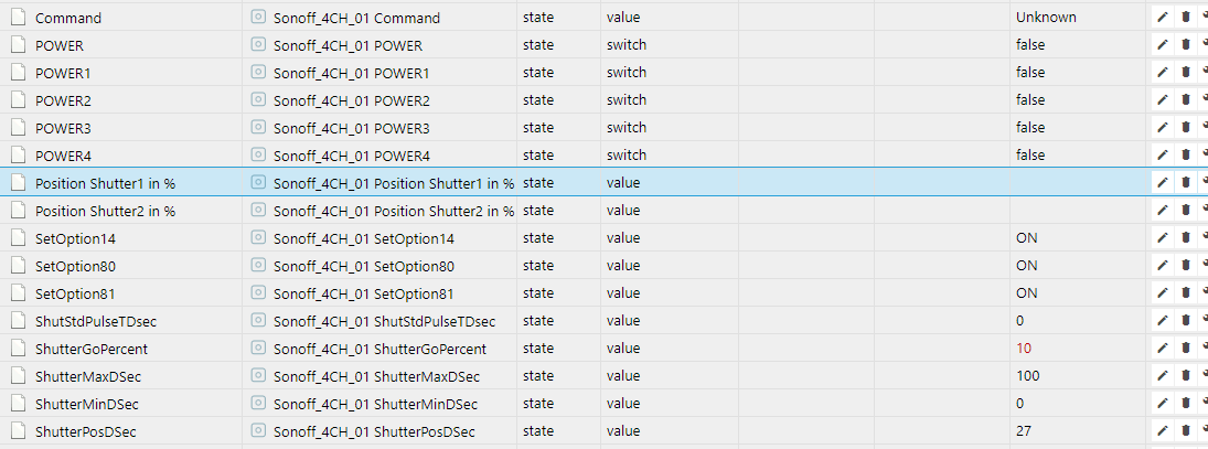
But all in all, you have done really a perfect work, thanks a lot.
[EDIT]
It was my mistake, I forgot to do an refresh - everything is fine....
speedymk1
on 11 Aug 2018
But now I found really a problem.
As you can see, there is only one possibility to send the shutter to xx%.
But in your firmware are 2 shutter with interlock - so it is not 100% defined.
Now always shutter 1 (Relay 1 and 2) go to the xx%....
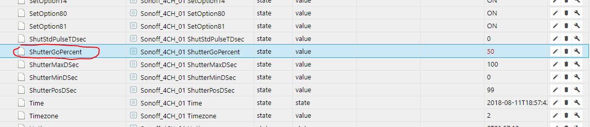
There should be 2 lines with ShutterGoPercent1 and ShutterGoPercent2...
speedymk1
on 11 Aug 2018
Hi
This is already implemented.
If you send the command shuttergopercent1 or shuttergopercent2, without any value, it will show you the % at which the shutter is. But not during the run, only when it stopped.
For your second topic....
You probably missed to add 1 or 2 after each command. You need to add to each command 1 OR 2, to tell, for which shutter the command is, if not it is for shutter 1 onl (default)
Example:
ShutterGoPercent2 50 => this sets the shutter 2 to 50%.
Wrong example:
If you use ShutterGoPercent 50, then it will assume that you want to move shutter one, right would be:
ShutterGoPercent1 50
lobocobra
on 11 Aug 2018
HI,
I know that I have to use the command
ShutterGoPercent1 50 or
ShutterGoPercent2 50
but in iobroker is only a object for ShutterGoPercent there is no object ShutterGoPercent2 or ShutterGoPercent1...
so maybe you could help me and could tell me how to use the command in iobroker, I got no answer how to use it.
I think it shuld be possible to send a command like ShutterGoPercent2 50 or other like Power1 true
[EDIT]
I think, the main point is, if you send
ShutterGoPercent1
you get following answer:
09:46:19 MQT: stat/Sonoff_4CH_01/RESULT = {"ShutterGoPercent":0}
and it should be
09:46:19 MQT: stat/Sonoff_4CH_01/RESULT = {"ShutterGoPercent1":0}
-->> ShutterGoPercent1
speedymk1
on 12 Aug 2018
Hi
I use Openhab. So I can not tell you, how to configure Iobroker. But if the SONOFF device receives a command like: cmnd/garten_buero-sz_storen/shutterGoPercent2 40
Then the device is moving correctly. Of course I am little help for you, how to do that in iobroker, but I am sure that you can define there like in Openhab the MQTT statement you want to send.
=> In Openhab you create an item, that does the trick.
In regard of the MQTT answer, you are correct and the SONOFF does not send back info on which device you requested the position.
=> I will fix that and upload here for you a new bin.
lobocobra
on 12 Aug 2018
Hi,
It will be nice, if you could correct the mqtt answer. This will also solve my problem. :)
Am 12. Aug. 2018, 13:37, um 13:37, lobocobra notifications@github.com schrieb:
Hi
I use Openhab. So I can not tell you, how to configure Iobroker. But
if the SONOFF device receives a command like:
cmnd/garten_buero-sz_storen/shutterGoPercent2 40
Then the device is moving correctly. Of course I am little help for how
to do that in iobroker, but I am sure that you can define there like in
Openhab the MQTT statement you want to send.In regard of the MQTT answer, you are correct and the SONOFF does not
send back info on the device.
=> I will fix that and upload here for you a new bin.--
You are receiving this because you were mentioned.
Reply to this email directly or view it on GitHub:
https://github.com/arendst/Sonoff-Tasmota/issues/824#issuecomment-412336832
speedymk1
on 12 Aug 2018
Here we are:
sonoff.ino.bin.zip
Now MQTT will report for which device you request the current status.
=> btw... there is a new feature. If the shutter is outside of the Min/Max, it will not move.
=> Example, if your shutter is at 0 and you push UP, with will not move, before it moved 0.1 sec.
lobocobra
on 12 Aug 2018
Perfect you are the best, I will try it tomorrow.
Am 12. Aug. 2018, 16:49, um 16:49, lobocobra notifications@github.com schrieb:
Here we are:
sonoff.ino.bin.zipNow MQTT will report for which device you request the current status.
--
You are receiving this because you were mentioned.
Reply to this email directly or view it on GitHub:
https://github.com/arendst/Sonoff-Tasmota/issues/824#issuecomment-412347831
speedymk1
on 12 Aug 2018
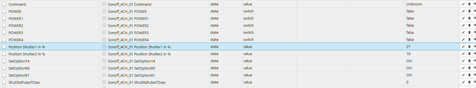
Hi again,
With the new firmware I got both possibilities and the command
ShutterGoPercent1 50
ShutterGoPercent2 50

work perfect -> THANK YOU
speedymk1
on 16 Aug 2018
Just for reference:
https://github.com/arendst/Sonoff-Tasmota/issues/3204
https://github.com/arendst/Sonoff-Tasmota/pull/719
 ascillato2
on 23 Aug 2018
ascillato2
on 23 Aug 2018
For those who are interested, I made now a new version that can deal with SPRINKLER or devices where you would like to know how much time there were on and how much this costs in Euro/Dollar.
=> It is programmed as a driver and can be activated with SETOPTION and can split channels.
=> I will transform my SHUTTER MOD to this version and also my previous HEATING MOD
Example: I want to know how much water I use with my sprinkler and how much this costs.
=> Sprinkler: https://github.com/lobocobra/sonoff-shutter (USE THE ONoffCOUNTER BRANCH)
=> Shutter: https://github.com/lobocobra/sonoff-shutter (USE THE MASTER BRANCH)
lobocobra
on 24 Aug 2018
Cross-posting from #3709
The two and two grouping is one scenario. Logically one would group 1&2 and 3&4. But, for unforeseen reasons, one might select the channels in each group differently. I wouldn't, but someone might (say in a retrofit where they now want to take advantage of this new firmware feature but they had already wired something differently. Just surmising). One might want only one group and then the remaining channels ungrouped.
The real reason this occured to me was a group of three scenario. I have this scenario for my ceiling fans. Three channels are used to control the speed of the fan. The interlocking varies from manufacturer to manufacturer.
Full interlock:
A - Low
B - Medium
C - High
Hybrid interlock:
A - Low
A&B - Medium
C - High
I use the fourth channel to control the ceiling fan light. This channel operates independently from the other three.
A part of the group configuration would be to specify which channels make up the group. Thus, if one has the ability to specify which three channels to group, then this same capability could be used in the 2/2 grouping to specify which channels are in each group. One could extend this thinking to a 5Ch switch (still two groups at most).
 meingraham
on 6 Sep 2018
meingraham
on 6 Sep 2018
I like your idea and will implement it in the next version
lobocobra
on 8 Sep 2018
Hi Lobocobra
I have Sonoff 4CH Pro R2
1- Does your firmware work with Sonoff 4CH Pro R2?
2-Which of these patterns can you use with your firmware?
3- Do you have the firmware in the bin format?

 achillealb
on 28 Sep 2018
achillealb
on 28 Sep 2018
@achillealb
1) Does your firmware work with Sonoff 4CH Pro R2? YES
On the picture above you have a SONOFF PRO R1, but I assume that you know this already and ordered a R2. I can tell you that there should be no issues a using R2 with my firmware. The differences are handled on lower level of the code by arendst.
=> But I will receive a R2 the next day and then I can tell for sure, but this should not stop you.
=> If there is an issue, let me know and we can fix it easily.
2) 2-Which of these patterns can you use with your firmware?
Looking at your picture above your shutter motor is simillar to mine and needs on one of the 2 phases
to be powered (never both) to go to either up or down. The firmware was build for that propose, if your motor works like this, then the answer is YES.
=> The small device on bottom right, seems only to be needed, if you do not use a sonoff or use the sonoff in the pulse mode. If you want to use pulse Switches you do not need this with my firmware.
If you want to work with sonoff in pulse mode, then I recommend you the regular firmware, as all the add-on make no sense (with a pulse for start and a pulse for stop, you will never know the exact position of your shutter).
Personally I do use 2 433mhz pulse-switches ( intertechno ywt , just google it) which are connected to the ch4-pro by 433mhz, but you can also use any other switch with my firmware. But in all cases, sonoff is not in the pulse-mode, only the switches are.
3- Do you have the firmware in the bin format?
Yes I have and here it is... and its posted above in a ZIP file. 9 posts before this one.
LINK
=> let me know if you need support
lobocobra
on 29 Sep 2018
https://www.ebay.com/itm/1pc-DC12V-G3-4-Normally-Closed-Brass-Electric-Solenoid-Water-Valve-Fast-Install/323265864011?hash=item4b4425a14b:g:zkcAAOSw~RFa2Htu:rk:1:pf:0 Would such a valve be a good choice for use with the Sonoff 4ch or the R2 or the Pro versions of this hardware.
Thanks in advance for advice!
 marksev1
on 30 Nov 2018
marksev1
on 30 Nov 2018
Do you have a 12V power supply for this application? Why not use a mains powered valve like the one used in a dish machine?
localhost61
on 30 Nov 2018
Anyhow no problem here. Just some relays in front and you’re done. Standard installation
stefanbode
on 1 Dec 2018
@lobocobra
Can you make a Pull Request with your Splitted Interlock Mode, please ?
Thanks
ascillato2
on 22 Dec 2018
I hope to see the "Interlock mask funcionality", written by @stefanbode, implemented in the master Tasmota code because is usefull for various scenario.
Thank you.
 GianCann
on 2 Jan 2019
GianCann
on 2 Jan 2019
@GianCann
I already asked to both @lobocobra and @stefanbode for a PR to add that feature to Tasmota but there is no answer so far. They must be very busy.
ascillato2
on 3 Jan 2019
@lobocobra @stefanbode we trust in you ;)
GianCann
on 4 Jan 2019
Ah sorry I was on vacation! I will do it :-)
lobocobra
on 4 Jan 2019
Hi,
Do you think it would be possible to use the interlock option only on 2 channels of a t1 with 3 ch???
I think that changing something on this code this would be possible, can you help me???
 Pako75
on 12 Jan 2019
Pako75
on 12 Jan 2019
Hi gents. I’m still on holiday and can not commit a change he master branch until feb 2019. THe requested masking of specific relays is already implemented and tested. The code changes are quite a few. Not very complicated.
stefanbode
on 13 Jan 2019
@ascillato2
Hi
I submitted the Pull Request and tested it. Sorry for the delay, I was away and then sick.
=> I submitted the version that is since 2 years in operation.
@Pako75
Can you please check? It should work on 3 channel as well. CH1/2 would be a group, CH3 alone
lobocobra
on 13 Jan 2019
Added with PR https://github.com/arendst/Sonoff-Tasmota/pull/4910 from @lobocobra
ascillato2
on 13 Jan 2019
Thanks a lot for sharing this and thanks everyone for sharing theirs ideas. Very appreciated. :+1:
ascillato2
on 13 Jan 2019
@lobocobra
Tomorrow i’ll try and let you know
Pako75
on 13 Jan 2019
Related issues
 j4k3
·
3Comments
j4k3
·
3Comments
 jensuffhaus
·
3Comments
jensuffhaus
·
3Comments
 renne
·
3Comments
renne
·
3Comments
 smadds
·
3Comments
smadds
·
3Comments
 abzman
·
3Comments
abzman
·
3Comments
Most helpful comment
@lobocobra
Can you make a Pull Request with your Splitted Interlock Mode, please ?
Thanks