Tasmota: S20 - Expansion by AM2301 Temperature & Humidity
Simple solution to expand the S20 by an AM2301 module.
Required:
- Jack socket 3.5 mm stereo
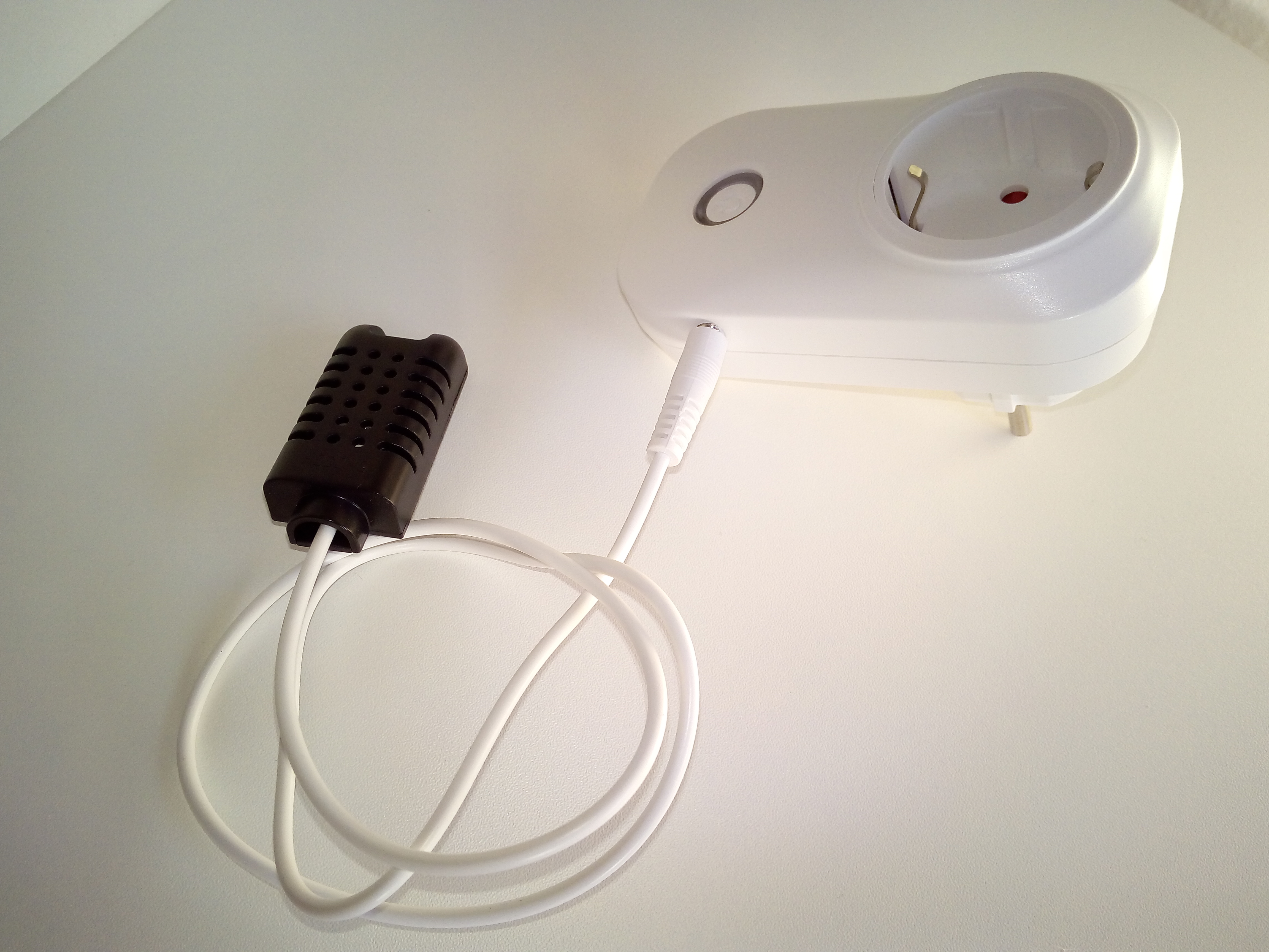
- AM2301 (DHT21) Digital Temperatur& Humidity Sensor
- 0.5m audio cable with 3.5mm stereo plug


 FabianHM
All 9 comments
What pins go to what from the S20 to the audo jack? How do I configure this as there is no gpio 14 for the s20 in tasmota? @FabianHM
 jat80
on 6 Aug 2017
jat80
on 6 Aug 2017
Thnx. Closed issue and add link in Wiki.
 arendst
on 9 Aug 2017
arendst
on 9 Aug 2017
@arendst I still don't know how to configure this?
Sorry don't worry, i've figured it out. Had a mind blank! lol. Thanks!
jat80
on 11 Aug 2017
For others:

arendst
on 11 Aug 2017
@arendst It's the wiring for the jack to correspond with the socket that would be the issue for most people.
jat80
on 12 Aug 2017
You need only connect 3 cables!
AM2301 red to S20 VCC (3.3V)
AM2301 black to S20 GND (Ground)
AM2301 yellow to S20 RX or TX (GPIO 1 or 3)
FabianHM
on 12 Aug 2017
@FabianHM how would someone wire the 3.5mm jack is what i'm saying. the above is obvious but if someone wants to make there own jack to the sensor themselves, which pins correspond with the jack pins - jack to jack socket.
jat80
on 12 Aug 2017
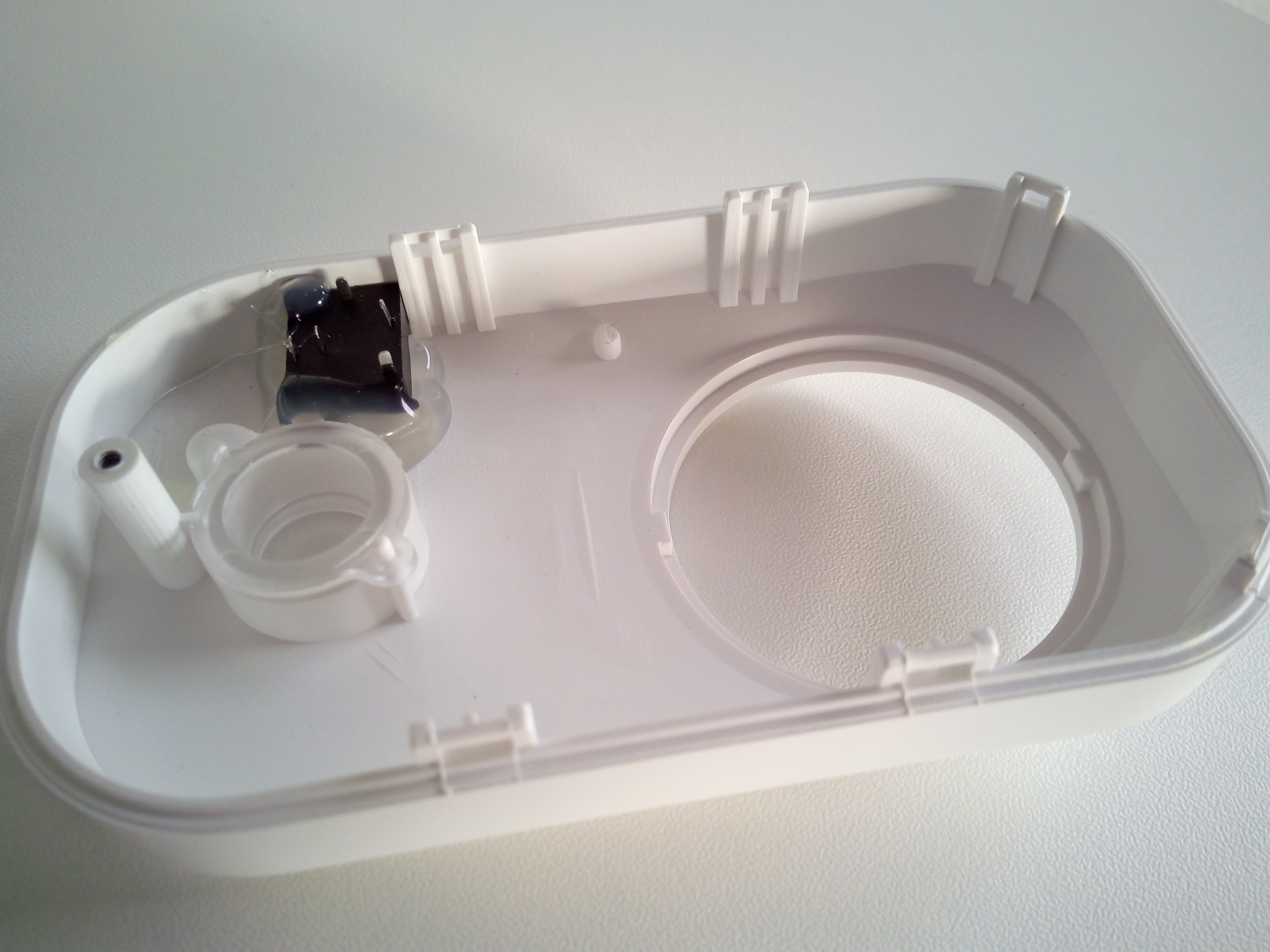
Connect the audio cable with 3.5mm stereo plug with the Jack socket.
Now simply measure the pin assignment of the socket with a measuring device. The allocation of the bushes are different in the case of some manufacturers.
FabianHM
on 12 Aug 2017
Is any pull-up resistor needed between VCC and DATA?
I am getting elevated Temp measurements from my AM2301s (I have tested with 3 different AM2301s) on different S20 sockets and I am trying to debug why.
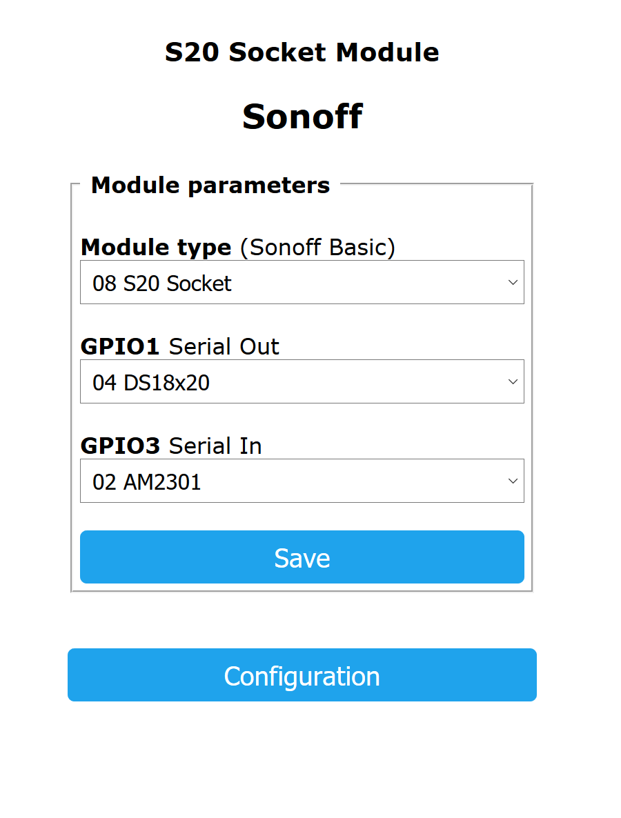
I have collected a DS18B20 to the other S20 pin to compare readings, see below:

Any ideas?
 CaptInsano
on 24 Sep 2017
CaptInsano
on 24 Sep 2017
Related issues
 belidzs
·
3Comments
belidzs
·
3Comments
 ximonline
·
3Comments
ximonline
·
3Comments
 TylerDurden23
·
3Comments
TylerDurden23
·
3Comments
 j4k3
·
3Comments
j4k3
·
3Comments
 grizewald
·
3Comments
grizewald
·
3Comments
Most helpful comment
For others: