Tasmota: Building an Espressif OTA (user{1,2}.bin) compatible Tasmota FW image
This is slightly off-topic, however -- in case my poor google skills didn't leave me in the lurch and indeed nobody managed to do so before -- might ease flashing the Tasmota supported itead/sonoff devices without HW/serial access.
I took a closer look at the original firmware, reversed engineered a few pieces and implemented a basic server which can communicate with the Sonoff devices (basically a subset of what the amazon services are doing for itead).
Goal is to use the original internal upgrade mechanism to flash custom firmware onto the devices without opening them, attaching a serial cable, potential soldering, pulling down GPIO0, you know the game...
By now I managed to trick a Sonoff device to download a custom FW from servers under my control, passing the verification, and eventually flashing the image. That's some fair progress, however the device doesn't boot.
My first naive try consisted of providing a sonoff.ino.bin instead of the original upgrade file the device would usually fetch.
Then I noticed, the original upgrade image doesn't contain the bootloader section, so I chopped off the first 0x1000 bytes.
Still, the device doesn't boot.
That could mean that
a) the original bootloader can't load the tasmota firmware (e.g. tasmota requires a modified bootloader to be loaded appropriately)?
b) the internal upgrade mechanism expects a different image format
After some research I figured the original FW uses the Espressif OTA functionality. This apparently makes use of some Ping-Pong, meaning, it splits the usable flash and always flashes the inactive part.
That also matches with the requests for files named "user1.bin" and/or "user2.bin".
Those -- the original upgrade files -- start with (HEX):
EA 04 00 01 04 00 10 40
The Tasmota built starts with (HEX at offset 0x1000):
E9 04 02 00 04 00 10 40
As you can see, the first 4 Bytes don't match, while the second 4 Bytes do.
The Tasmota image header matches the Espressif documentation[1] about how an image should like (always starting with E9).
I couldn't find any documentation on what the image header in the original upgrade images is supposed to represent.
Long story short: If case b) applies ("the internal upgrade mechanism expects a different image format"), what is the that image format / header and (how) could build I build a Tasmota FW matching that image format criteria? If a) applies ("the original bootloader can't load the tasmota firmware"), can we workaround that somehow, at least for an intermediate image providing the Tasmota OTA functionality?
 mirko
mirko
All 77 comments
The world is full of funny coincidences... after sometime thinking about this i had finally started looking into this last night as well.
I presume you are using a little DNS trickery and setting up a websocket which issues the update command (along with custom url). One thing to note is that i don't believe with standard tools you can update the bootloader OTA (but maybe you can by directly overwriting the flash... it wouldn't be 'safe' from possible corruption - but in this case the only thing that could happen is to have to flash it via serial which is where we have come from anyway).
I think the first question to determine is which bootloader they are using - using esptool i believe you can dump flash from an arbitrary memory location maybe we can get some clues on their bootloader.
PS: The latest firmware that i sniffed an upgrade to (2.0.2) seems to use SSL end to end for the websockets so this could close this avenue in the future if they start shipping with newer firmware
PPS: From sniffing it would also be possible to maintain compatibility with the ewelink app infrastructure so devices could be controlled by both mqtt and the ewelink - not sure if that would be usefull for anyone..?
 khcnz
on 23 May 2017
khcnz
on 23 May 2017
http://esp8266-re.foogod.com/wiki/SPI_Flash_Format#0xea_Header
Seems its a newer boot mode format (boot mode 1 vs boot mode 2)
khcnz
on 23 May 2017
khcnz
on 23 May 2017
Glad to hear somebody else is also looking into this!
The hint towards the 2 image formats explains a lot - unfortunately it doesn't provide an easy solution to the issue.
From analyzing the original firmware there's no (proper) way of flashing the bootloader - only the "user1" and "user2" partitions - so flashing the bootloader from within the internal original upgrade procedure doesn't seem feasible.
So, if I'm understanding correctly, Tasmota images use the old image format (0xE9), including an bootloader which supports the old image type, while the original FW uses a bootloader which supports the new image format?
If correct, I guess the way to go would be to build (minimal) Tasmota images with the new 0xEA header(?)
Update: it seems esptool.py as well as the arduino esptool only create 0xE9 images. :/
mirko
on 23 May 2017
Wohoo! I just managed to flash and boot a tasmota firmware image onto a sealed Sonoff Basic!
Tutorial and code will follow.
mirko
on 24 May 2017
(Assuming we can find a toolchain that support building the new format) I think you could maybe create a very minimal 0xEA firmware whose sole purpose is to flash the bootloader to the tasmota and enable the second stage firmware flash - however still dependent on being able to flash over the current bootloader while its running... my knowledge gets very slim here but from some reading I think the bootloader is loaded in ram... so it could be possible to flash while its running (maybe....).
khcnz
on 24 May 2017
Edit - wow! nice! A wiki page would probably be the best place
Assuming you managed to compile tasmota with 0xEA bootloader I also guess this means we could retain backwards compatibility with the existing firmware for those who want/need to roll back?
khcnz
on 24 May 2017
Yes, I didn't touch the bootloader, just modified the image.
mirko
on 24 May 2017
please double-check that you can do an OTA upgrade from tasmota to a new tasmota
image after this.
 davidelang
on 24 May 2017
davidelang
on 24 May 2017
please double-check that you can do an OTA upgrade from tasmota to a new tasmota image after this.
Could you elaborate your concerns?
I'm still struggling with forcing the Sonoff to flash our custom image to the user1 partition, as -- depending what part is (in)active -- it might get flashed to user2 which is bad for several reasons.
My first thought was to figure out which image the device asks for and provide a faulty image to get the device booting from the other partition, however I noticed quite quickly that the only faulty thing in this logic is me:
When the currently running system is stored on user1 (user1 == active), then we'd flash user2. Providing a faulty image only result in the bootloader not being able to boot user2 and again boot into user1.
UPDATE:
The only way I come up with right now is, in case the device asks for the user2 image (meaning user1 == active), to override the internal data segment, which comes right after the user2 one, as the internal data section stores the information for the bootloader which partition is the currently active one.
But that sounds rather nasty and requires us to know the exact flash size to calculate the exact extra padding.
mirko
on 24 May 2017
you have been able to get tasmota running from the base build, but by not
replacing the bootloader.
my concern is that since you didn't replace the bootloader, trying to d a
tasmota -> tasmota OTA upgrade could possibly not work (or require changes to
tasmota)
If it's possible/required to do different update URLs for the two 'slots' in the
router, that may not be a bad thing, we are getting to the point where size
limits are pushing us to the need to do a 'two step' upgrade (first to a minimal
build, then to a full build)
davidelang
on 24 May 2017
my concern is that since you didn't replace the bootloader, trying to d a tasmota -> tasmota OTA upgrade could possibly not work (or require changes to tasmota)
I see, though I figured tasmota also flashes the bootloader, doesn't it?
If so, then -- once tasmota is running (even with the original bootloader) -- it would OTA-update the whole flash starting from 0x0 and therewith also replace the bootloader, wouldn't it?
Or does tasmota use the bootloader to perform the upgrade? That would indeed be an issue then.
If it's possible/required to do different update URLs for the two 'slots' in the router, that may not be a bad thing, we are getting to the point where size limits are pushing us to the need to do a 'two step' upgrade (first to a minimal build, then to a full build)
Good to know! That will definitely make certain things easier.
However the current problem is, that the tasmota build (with the 0xEA header) only boots when being flashed as user1.bin. When being flashed as user2.bin it doesn't.
Taking a closer look at the original upgrade images user1.bin and user2.bin also slightly differ.
I assume the place where they'll be flashed onto flash is somehow encoded and read/used by the bootloader.
mirko
on 24 May 2017
On Wed, 24 May 2017, Mirko Vogt wrote:
my concern is that since you didn't replace the bootloader, trying to d a tasmota -> tasmota OTA upgrade could possibly not work (or require changes to tasmota)
I see, though I figured tasmota also flashes the bootloader, doesn't it?
If so, then -- once tasmota is running (even with the original bootloader) -- it would OTA-updates the whole flash starting from 0x0 and therewith also replaces the bootloader, wouldn't it?
Or does tasmota use the bootloader to perform the upgrade? That would indeed be an issue then.
I'm not sure. The max size you can OTA on tasmota is 1/2 (memory size -
bootloader) so I think it doesn't replace the bootloader with an OTA upgrade.
When arendst is back he can comment on this with a lot more knowledge. I'm just
raising potential issues in the hope that you can check them and make this rock
solid.
David Lang
k
davidelang
on 24 May 2017
It's hard to say without knowing a little more about the process you are using to modify your tasmota image to boot?
I presume you have the user1.1024 and user2.1024 images from itead? When you diff them there are considerable differences (starting at the simple like byte 4 is 01 or 02 depending on which file).
I would guess that itead are using the espressif OTA mechanism - you can see more here http://www.espressif.com/sites/default/files/99c-esp8266_ota_upgrade_en_v1.6.pdf and it describes how to create the two versions aside from the bye mentioned above I believe memory addresses differ ti think..?
khcnz
on 24 May 2017
You may also want to look at the code in the Arduino ESP8266 updater https://github.com/esp8266/Arduino/blob/master/cores/esp8266/Updater.cpp - may give some hints
khcnz
on 24 May 2017
It's hard to say without knowing a little more about the process you are using to modify your tasmota image to boot?
I'm sorry, I didn't mean to beat around the bush. esptool.py can indeed create v2 images, although that's undocumented. From the source I figured that the "--version" parameter -- while usually (and according to the docs) printing the version string of the tool -- in combination with "elf2image" accepts an parameter, specifying the version of the image to be created.
tl;dr: < esptool.py elf2image --version 2 sonoff.ino.elf > - sonoff.ino.elf in this case is the tasmota image created by the Arduino frontend.
I would guess that itead are using the espressif OTA mechanism
Yes, according to my image analysis they most certainly are.
you can see more here http://www.espressif.com/sites/default/files/99c-esp8266_ota_upgrade_en_v1.6.pdf and it describes how to create the two versions aside from the bye mentioned above I believe memory addresses differ ti think..?
Oh, interesting! So far I only stumbled over documents from Espressif describing how to use their SDK to build user1.bin and user2.bin which wasn't very helpful. The document you mentioned is way more detailed and helpful, let's see what to make out of it.
EDIT: The most interesting part of the doc probably is:
user1.bin and user2.bin are same software placed to different regions of flash. The only difference is address mapping on flash.
However it doesn't get into detail.. will now try my luck on the OTA source
mirko
on 25 May 2017
Great! One other thing that was confusing me that may help you... based on my reading of the Arduino IDE Uploader.cpp Arduino OTA mechanism (that tasmota uses) doesn't seem to ever flash OTA user 1 image... only ever user 2. User1 is left for fallback as far as I can tell (see how it calculates the start address of where to write the flash to. Thats why the fact that the tasmota/arduino image has the first 0x1000 as the bootloader is irrelevant. its written to a space that isn't used (but according to the link above its kept for symmetry reasons).
This differs from espressif as far as i can tell where they write alternatively between the two - you can tell which one is currently executing with the call system_upgrade_userbin_check
khcnz
on 25 May 2017
Check this out - tasmota only uses linker script 1
https://github.com/arendst/Sonoff-Tasmota/tree/master/arduino/version%202.3.0/tools/sdk/ld
Look at this example of a make script building 1 & 2 images https://github.com/jeelabs/esp-link/blob/master/Makefile
I think we just need to have a secondary ld script
khcnz
on 25 May 2017
One last link :) https://github.com/espressif/ESP8266_RTOS_SDK/tree/master/ld you can compare eagle.app.v6.new.1024.app1.ld and eagle.app.v6.new.1024.app2.ld
I think if you changed the tasmota over-ride and change irom0_0_seg from 0x40201010 to 0x40281010 it will work
khcnz
on 25 May 2017
With these user1 and user2 images I see two concerns:
- What happens to the arduino EEPROM flash area at address fb000? Is it left untouched by the max size image?
- How about the nice arduino feature of being able to OTA upload a larger image than half the flash size as it uses dynamic image loading
Just some thoughts during holiday...
 arendst
on 25 May 2017
arendst
on 25 May 2017
What happens to the arduino EEPROM flash area at address fb000? Is it left untouched by the max size image?
Well, I'd say (for now) this method only allows flashing images < 0xfb000−0x81000 = 488KB which at least a minimal tasmota image shouldn't exceed (or would it?).
From there we could second-stage flash a normal image, then also incl. the bootloader.
Does that make sense?
How about the nice arduino feature of being able to OTA upload a larger image than half the flash size as it uses dynamic image loading
Honestly, I've absolutely no idea as this is my first arduino project I kinda involve myself and frankly this arduino world doesn't appear to be mine so I'm not sure I'd be of any help here..
Just some thoughts during holiday...
Enjoy your holidays! When are you gonna be back? And where are you? And how is it? :)
mirko
on 25 May 2017
@mirko How did you go with building a user2 image?
@arendst I can't find any info on dynamic sized arduino images but I have done a lot more digging and finally have my head around how the boot rom, bootloader and ota is working.
Boot Rom - this is flashed into the actual ESP (not the flash chip). Used to setup system / spi flash etc and then run normal bootloader. Also takes care of the process for flashing via UART when put into flash mode. The boot rom can not be updated but can be dumped out as it is mapped to a flash memory address Reverse engineering info here
Bootloader - this is normally flashed to 0x0 - espressif and arduino both have their own bootloaders and both work very differently and have have quite strict flash layouts. The bootloader is essentially responsible for any custom setup and also determining the entry point to the 'real' application. See more below
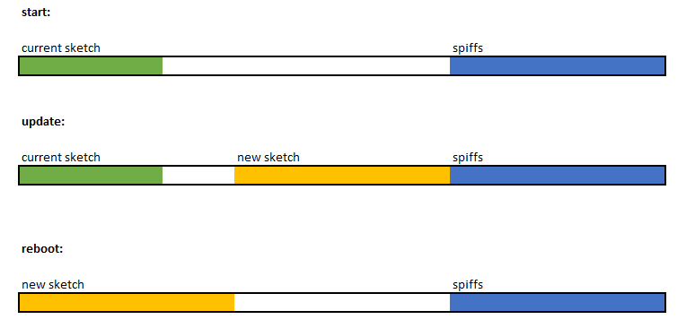
Espressif Bootloader - Splits flash essentially in 1/2 - an image can be flashed to either half and the bootloader is responsible for determining which to execute. 'Safety' is created by writing to the other 1/2 of flash from the one being used and then switching over at next boot.
Arduino OTA - Works quite differently - still splits the flash in 1/2 but OTA updates always save the new sketch to the second half of flash. The bootloader then copies the newsketch from the second half of flash back to 0x0 on next boot.

So.. in conclusion
- It seems should be possible for sure to create both user1/user2 images that the espressif bootloader will work with - just need to check out how the layout is flashed (especially since the images from iteads servers don't seem to have the bootloader AFAIK - just the application code. Perhaps these are even just stub images that don't do much but allow for a secondary image to be loaded? Flashed to match the arduino bootloader?
The the arduino bootloader is pretty restrictive if we want to include larger than 1/2 of flash size images (and when i say restrictive i mean not possible).
There is a 3rd party esp8266 bootloader rboot that seems to fit the bill and allows arbitrary # of roms and rom sizes. I would suggest we would have 3 binaries
- Bootloader
- Very very small (smaller than minimal) upgrade rom - would need to be able to boot into this rom and accept a new image. Whats the best way to do this while still maintaining flexibility - download from a url? webpage? The more options we add the less space is available for the main application.
- Normal application / sketch
Obviously depending on how small the small upgrade rom could get - we could have a lot more flash available for the main application
Thoughts?
(edited images to be inline)
khcnz
on 27 May 2017
the #define BE_MINIMAL is intended to do this. It builds an image that has
almost all features disabled, but still has the wifi and webserver functionality
so that you can tweak configs and download/install a new image.
If it's not small enough, we would need to figure out what's eating the space
and can be disabled.
davidelang
on 27 May 2017
From memory the minimal still includes MQTT and there is a ton of config upgrade logic that wouldn't need to exist, and the webserver code is massive as well. Even just the base arduino and espressif libraries add a ton.
Clearly the smaller it can be the better - but the smaller it is made the less ways we could support upgrade (the smallest way would probably only to support connecting to a defined wifi network and pulling from a defined url). Of course then you get into questions like dns/mdns, HTTPS, static ips etc etc.
khcnz
on 27 May 2017
there isn't actually a way right now to not compile in the mqtt code.
I think the webserver is still needed to be able to direct an upgrade and
configure things like network connection.
As long as the minimal build + real build < flash space (- bootloader), it
should be good enough
It should also be possible for the firmware to overwrite the bootloader to
conver it from the stock sonoff firmware to the one that tasmota has been using.
davidelang
on 27 May 2017
https://github.com/espressif/ESP8266_RTOS_SDK/tree/master/ld you can compare eagle.app.v6.new.1024.app1.ld and eagle.app.v6.new.1024.app2.ld
I think if you changed the tasmota over-ride and change irom0_0_seg from 0x40201010 to 0x40281010 it will work
This indeed sounded like the hint, however the images I managed to create (user1 = without that change, user2 = with that change) only differ in what I think is the build timestamp.
Nothing like the diff between the original user1/user2 upgrade images :/
mirko
on 27 May 2017
the #define BE_MINIMAL is intended to do this. It builds an image that has almost all features disabled, but still has the wifi and webserver functionality so that you can tweak configs and download/install a new image.
BTW, that fails for me (current master) with:
"/home/mirko/.arduino15/packages/esp8266/tools/xtensa-lx106-elf-gcc/1.20.0-26-gb404fb9-2/bin/xtensa-lx106-elf-g++" -D__ets__ -DICACHE_FLASH -U__STRICT_ANSI__ "-I/home/mirko/.arduino15/packages/esp8266/hardware/esp8266/2.3.0/tools/sdk/include" "-I/home/mirko/.arduino15/packages/esp8266/hardware/esp8266/2.3.0/tools/sdk/lwip/include" "-I/tmp/arduino_build_518542/core" -c -w -Os -g -mlongcalls -mtext-section-literals -fno-exceptions -fno-rtti -falign-functions=4 -std=c++11 -MMD -ffunction-sections -fdata-sections -DF_CPU=80000000L -DLWIP_OPEN_SRC   -DARDUINO=10803 -DARDUINO_ESP8266_ESP01 -DARDUINO_ARCH_ESP8266 -DARDUINO_BOARD="ESP8266_ESP01"  -DESP8266 "-I/home/mirko/.arduino15/packages/esp8266/hardware/esp8266/2.3.0/cores/esp8266" "-I/home/mirko/.arduino15/packages/esp8266/hardware/esp8266/2.3.0/variants/generic" "-I/home/mirko/Arduino/libraries/PubSubClient/src" "-I/home/mirko/.arduino15/packages/esp8266/hardware/esp8266/2.3.0/libraries/Ticker" "-I/home/mirko/.arduino15/packages/esp8266/hardware/esp8266/2.3.0/libraries/ESP8266WiFi/src" "-I/home/mirko/.arduino15/packages/esp8266/hardware/esp8266/2.3.0/libraries/ESP8266HTTPClient/src" "-I/home/mirko/.arduino15/packages/esp8266/hardware/esp8266/2.3.0/libraries/ESP8266httpUpdate/src" "-I/home/mirko/Arduino/libraries/ArduinoJson/src" "-I/home/mirko/.arduino15/packages/esp8266/hardware/esp8266/2.3.0/libraries/ESP8266WebServer/src" "-I/home/mirko/.arduino15/packages/esp8266/hardware/esp8266/2.3.0/libraries/DNSServer/src" "/tmp/arduino_build_518542/sketch/sonoff.ino.cpp" -o "/tmp/arduino_build_518542/sketch/sonoff.ino.cpp.o"
/home/mirko/src/Sonoff-Tasmota.git/sonoff/sonoff.ino: In function 'void GPIO_init()':
sonoff:2384: error: 'dht_setup' was not declared in this scope
         if (dht_setup(i, mpin)) {
                              ^
[..]
exit status 1
'dht_setup' was not declared in this scope
that section should be wrapped with #ifdef USE_DHT
a patch similar to:
diff --git a/sonoff/sonoff.ino b/sonoff/sonoff.ino
index c022965..203d60a 100644
--- a/sonoff/sonoff.ino
+++ b/sonoff/sonoff.ino
@@ -2380,6 +2380,7 @@ void GPIO_init()
led_inverted[mpin - GPIO_LED1_INV] = 1;
mpin -= 4;
}
+#ifdef USE_DHT
else if ((mpin >= GPIO_DHT11) && (mpin <= GPIO_DHT22)) {
if (dht_setup(i, mpin)) {
dht_flg = 1;
@@ -2388,6 +2389,7 @@ void GPIO_init()
mpin = 0;
}
}
+#endif
}
if (mpin) {
pin[mpin] = i;
davidelang
on 27 May 2017
BTW, this is the current state of my implementation instructing a sonoff device to fetch and flash a custom image from an arbitrary (reachable) server: https://pb.nanl.de/show.php?id=2765&hash=14959135
mirko
on 27 May 2017
This indeed sounded like the hint, however the images I managed to create (user1 = without that change, user2 = with that change) only differ in what I think is the build timestamp.
Nothing like the diff between the original user1/user2 upgrade images :/
Are you sure you changed the correct file? I just rebuilt mine with the change and the files were very different (in a similar way to the difference between itead user 1 and user2 files).
Not sure what platform you are running on but it is not this file Sonoff-Tasmota\arduino\version 2.3.0\tools\sdk\ld\ but the one in ArduinoDatapackages\esp8266\hardware\esp8266\2.3.0\tools\sdk\ld that needs modification.

khcnz
on 28 May 2017
Are you sure you changed the correct file?
I thought so...
Not sure what platform you are running on but it is not this file Sonoff-Tasmota\arduino\version 2.3.0\tools\sdk\ld\
Oh...
ArduinoDatapackages\esp8266\hardware\esp8266\2.3.0\tools\sdk\ld[eagle.flash.1m64.ld]
That actually did the job!
In my case it's: /home/mirko/.arduino15/packages/esp8266/hardware/esp8266/2.3.0/tools/sdk/ld/eagle.flash.1m64.ld (Linux)
IT WORKS!
I assume /home/mirko/.arduino15/packages/esp8266/hardware/esp8266/2.3.0/tools/sdk/ld/eagle.flash.1m64.ld is the linker script coming from the esp8266 library? So the tasmota linker scripts are not used at all when using the Arduino environment?
mirko
on 28 May 2017
When using the arduino ide you are supposed to replace the inbuilt arduino linker script with the one inside tasmota - the only difference is theo has provided a non SPIFFS version (which arduino ide doesn't have out of the box) - there are some instructions here https://github.com/arendst/Sonoff-Tasmota/wiki/Prerequisite
khcnz
on 28 May 2017
And by "it works" I assume you mean you can now flash both User1 and User2 images "OTA" from stock itead firmware and they run. I presume you are still stripping off the first 0x1000 bytes from the build that arduino does (to remove the bootloader) - since the itead/espressif ota isn't expecting the bootloader.
Ideally we can now find a way to bootstrap replacement of the bootloader as well as I think right now OTA won't work from the booted tasmota image since the OTA process works differently.
khcnz
on 28 May 2017
And by "it works" I assume you mean you can now flash both User1 and User2 images "OTA" from stock itead firmware and they run.
Correct.
I presume you are still stripping off the first 0x1000 bytes from the build
As I convert the ELF images to the v2 image format -- which don't have the bootloader included -- I don't have to chop off the first 0x1000 from those.
mirko
on 28 May 2017
Ideally we can now find a way to bootstrap replacement of the bootloader as well as I think right now OTA won't work from the booted tasmota image since the OTA process works differently.
Indeed it doesn't work. But right now mainly because the image (I assume) gets now flashed to user1 (as we're running our custom tasmota image right now from user2 as we flashed from the original FW from user1) however the bootloader still tries to boot from user2.
As the tasmota image is a bit bigger -- when being written to user1 -- it also (again, I only assume) overrides parts of the user2 partition. So booting user2 fails after the update.
This would also imply the bootloader doesn't get flashed indeed via OTA since I'd expect the tasmota bootloader loading from 0x1000 (user1).
So we either need to replace the bootloader (which would be best I guess as then the device would be in a state as it would be after being flashed via serial) or tell the original bootloader to switch back to user1 after successful flashing (which would imply using and modifying the system information partition (last 16KB)).
mirko
on 28 May 2017
From my reading of the Arduino OTA and Espressif OTA code I think the problem you will be running into is the the Arduino OTA (which is running once you flash) is expecting a bootloader header.
Checkout packages\esp8266\hardware\esp8266\2.3.0\cores\esp8266 Arduino saves the following info to RTC which the Arduino bootrom tries to pickup
if (_command == U_FLASH) {
eboot_command ebcmd;
ebcmd.action = ACTION_COPY_RAW;
ebcmd.args[0] = _startAddress;
ebcmd.args[1] = 0x00000;
ebcmd.args[2] = _size;
eboot_command_write(&ebcmd);
So write out the data from _StartAddress on flash to 0x0 with _size (so obviously the bootloader must be replaced)
but the Espressif bootloader tries to run from the following for user2
0x4010800c((((offset + 4) >> 1) << 12) + 0x1000);
Which i haven't math'd but pretty sure that its saying find 1/2 the flash size then skip the first 0x1000 bytes - which is going to put it 0x1000 bytes into your image - rather than the start of it.
khcnz
on 28 May 2017
Actually edit that - I think a closer reading of Update.cpp and the Arduino OTA flashlayout - it is writing the Update to a block aligned flash address just after the end of the current sketch - note 1/2 way...
Suggest if you updated Updater.cpp (need to triple check this is what is actually being used by tasmota) so that the image is written out to 0x4010800c((((offset + 4) >> 1) << 12) + 0x1000); it would work - but as you say you may end up hitting into other flash regions that the Espressif code uses depending on code size.
khcnz
on 28 May 2017
I wonder if it makes sense at all to get that into the tasmota project or if it would be better to create a very own espressif-ota->arduino bootstrap project which compiling would result in 2 minimal images (user1.bin / user2.bin), having the v2 image format right away, and providing Arduino OTA functionality (incl. support for flashing the bootloader) for properly switching to custom FW (e.g. tasmota)
Or we add code to the tasmota project (=OTA code) checking which bootloader is used and respectively replace it or not. The image the Tasmota/Arduino OTA code expects has a bootloader included anyway and apparently just gets chopped off after being transmitted via HTTP.
mirko
on 28 May 2017
Agree I think a standalone would probably be best - working on the assumption you can't flash what you are running I think we need three parts
- User1 image - ony purpose is to kick-off the user2 image update using the Espressif OTA functionality as we can't overwrite bootloader while running as user1 image
- User2 image - Download "User3" image and flash directly using SPI erase/write to 0x0. Would need to manipulate the flash to change which image is booted next time.
- An Arduino IDE build (can be tasmota).
khcnz
on 28 May 2017
I put the script on github now:
https://github.com/mirko/SonOTA
and published the progress and findings in a blog post:
http://blog.nanl.de/2017/05/sonota-flashing-itead-sonoff-devices-via-original-ota-mechanism/
I'm happy about criticism / feedback including tips pointing out missing / insufficient credits.
mirko
on 28 May 2017
Nice writeup! I might just get some time this week to do some coding rather than just google kung-fu.
khcnz
on 28 May 2017
Some additional info that could be helpful for creating 'dummy' OTA builds which i hope to look at soon.
From dumping out the firmware before/after the ewelink app stores the wifi credentials you enter at
1) SSID: 0x79000 -> 0x7901F (null terminated / padded) - Up to 30 chars +0
2) Password: 0x79020 -> 0x79066 (null terminated / padded) - Up to 70 chars including 0
khcnz
on 30 May 2017
I have a custom little flashing image now that can install OTA and then reflash the other 1/2 of flash not currently running and force the reboot and switch to the new image. But working on making it a bit simplier (from a user perspective) but a bit more complicated from a code perspective.
Pretty sure I can make this work with one image that can run as an Espressif image on the second ROM slot (and always get there even if user1 is requested) - then flash on the Arduino bootloader and then copy the running image on rom 2 back to slot 1 while dynamically changing the header so that the arduino bootloader can start it up... After that you would just need to connect to the a webpage and flash tasmota.
khcnz
on 31 May 2017
I have a custom little flashing image now that can install OTA and then reflash the other 1/2 of flash not currently running and force the reboot and switch to the new image. But working on making it a bit simplier (from a user perspective) but a bit more complicated from a code perspective.
Pretty sure I can make this work with one image that can run as an Espressif image on the second ROM slot (and always get there even if user1 is requested) - then flash on the Arduino bootloader and then copy the running image on rom 2 back to slot 1 while dynamically changing the header so that the arduino bootloader can start it up... After that you would just need to connect to the a webpage and flash tasmota.
Yeah, that sounds like great process! Thanks for your effort on this!
mirko
on 1 Jun 2017
Getting pretty close to have this working end to end will probably finish over weekend. Currently have a standalone version and thinking it will easily integrate into tasmota with #ifdefs so that its a one OTA rom download from stock to running tasmota.
khcnz
on 2 Jun 2017
Been following this discussion in the background and really interested/exciting to see the progress. I would ideally like to integrate it with different firmware from Tasmota so using some #ifdefs would certainly be a great implementation, though I guess this will be more complex than having a first flash file which is universal (and just enables the update page), followed by flashing the actual arduino bin file...
 cjcharles0
on 2 Jun 2017
cjcharles0
on 2 Jun 2017
I also just pushed a new version of the SonOTA script which now can also provision the device (without the need of the proprietary app).
This work is based on the research of Jan Almeroth ( https://wiki.almeroth.com/doku.php?id=projects:sonoff#pairing ).
Neat side effects are that while provisioning we can now also specify the serving host, which means
- we do not need to spoof / redirect DNS requests
- it doesn't need to run as root (as we can also specify the port and don't need to listen on 443)
anymore.
mirko
on 2 Jun 2017
Nice update mirko - this is very very good!
On my end I have mixed news
Dynamic Self Patching idea - Download to User2, rewrite bootloader and copy over application to slot 1. Bootloader successfully replaced and reboot works fine - HOWEVER the symbols inside irom.text now sitting in the first half of flash still resolve to memory address mapped in the 2nd half of the flash partition. Everything works until you can erase the second half of flash (and of course therefore can't do another following OTA.
By comparing the differences between user1/user2 bin files I have worked out how I can rewrite the memory addresses on the fly with some heuristics and this works well for a standalone example - however fails with something as complex as Tasmota.
So may have to go back to the 3 file idea
1) User 1 Espressif Image which Downloads User2 Espressif Image
2) User 2 Espressif Image which downloads Tasmota and rewrites to 0x0
3) Tasmota
The 3 file version isn't quite as neat but does work - i'll guess I'll have to put aside the more complicated version until I can find some references on the layout inside the irom portion. Should be able to post some code tomorrow of the 3 step version.
PS: If anyone knows how to parse the irom section and remap the symbols please get in touch. Remapping is easy just involves subtracting 0x80000 from memory addresses of all items.. but knowing which values are memory addresses and which are just values is proving hard
khcnz
on 4 Jun 2017
If anyone knows how to parse the irom section and remap the symbols please get in touch
I dropped Richard Burtons[1] an email pointing to that ticket - he might have the insights and be willing to provide some help on this.
mirko
on 4 Jun 2017
You can't remap the application at runtime - it isn't simply a case of the base address being stored in the header, the elf is linked with that address baked in in ways you will not be able to understand / adjust in the completed binary. You need to have two separate roms - one for the lower 1/2 and one for the upper 1/2. Yes, that isn't as neat but it's no big deal. If there had been a bigger flash than 8mbita on the device you could have used a single rom, by spacing them in separate mbs of flash each mb will be mapped to the same base address in memory. Of course they have used the smallest flash they can for cost purposes. Luckily it's trivial to create both versions at link time and then when you ota you just need to request the correct one file be downloaded and flashed.
 raburton
on 5 Jun 2017
raburton
on 5 Jun 2017
Thanks for responding Richard - much appreciated - I have some follow up questions though
You can't remap the application at runtime - it isn't simply a case of the base address being stored in the header, the elf is linked with that address baked in in ways you will not be able to understand / adjust in the completed binary.
Well clearly it is interpretable - after all that's how its run as instructions on the CPU! The offsets are actually very simple (different by exactly 0x080000 of course). If you binary compare the two builds you can see the changes are pretty straight forwards, and with a simple/small build you can get away with some logic basically saying rewrite on the fly any 4byte aligned 32bit address between 0x40280000 -> 0x402B0000 by subtracting 0x80000. This actually works fine with smallish builds (mostly by chance to be fair). On larger builds the chance goes up you get something that shouldn't actually be modified as its not an address but matches the pattern described above.
I guess I was hoping there would be some info on how to read the actual section (have read out the headers etc), that way could iterate through the sections and only manipulate the address. Tools like idapro can obviously do this - however the question would become if a) its feasible to do in a small micro, especially when you can't hold the entire section in ram at once and b) worth the time :)
If there had been a bigger flash than 8mbita on the device you could have used a single rom, by spacing them in separate mbs of flash each mb will be mapped to the same base address in memory.
Yea I started down this rabbit hole briefly while looking at your rboot source but alas as you say you can only map in 1mB chunks.
You need to have two separate roms - one for the lower 1/2 and one for the upper 1/2. Yes, that isn't as neat but it's no big deal.
Have just pushed my original code up to here https://github.com/khcnz/Espressif2Arduino that effectively does this. I haven't yet tried this with your code @mirko but pretty sure it will work end to end - i would be interested to know if it picks up the wifi credentials you entered in the itead app?
Have also created a tiny utility for flip-flopping / ping-ponging between the two images on the device https://github.com/khcnz/EspressifRomSwitcher
khcnz
on 5 Jun 2017
@mirko I think with a bit more work on both of our ends I think we could
1) Provide small one off python script to end users that provisions device and points to
2) Public webserver running websockets code + Espressif2Arduino x2 Images + Stock sonoff Image
That way we / people can 'jailbreak' the device very simply with no setup other than needing to be able to run one python script.
khcnz
on 5 Jun 2017
Well clearly it is interpretable - after all that's how its run as instructions on the CPU!
True, but I didn't say the CPU couldn't understand them, I said "you" (though that wasn't supposed to be personal or rude - I meant your code, unless you plan to write an embedded version of IDA in less than half a mb).
The offsets are actually very simple (different by exactly 0x080000 of course). If you binary compare the two builds you can see the changes are pretty straight forwards, and with a simple/small build you can get away with some logic basically saying rewrite on the fly any 4byte aligned 32bit address between 0x40280000 -> 0x402B0000 by subtracting 0x80000.
You can identify 4 byte sequences, that are 4 byte aligned, which when interpreted as uint32 fall within that range, but you have no idea if it is an address or even a number, so it would be unsafe to modify them, as you have found. Also, the ram sections are checksummed, and if you alter those sections without updating the checksum it will not boot.
I'm afraid the only option to having two copies of the rom on flash is to have two differently linked images. There are other strategies, which I think have been mentioned in passing before here, like downloading the new image to the end of the rom, and having the boot loader copy it to the first slot on next boot, so you only ever have a slot one rom. The extra complexity and the lack of fallback in case of a bad flash though make this a much less sensible option.
raburton
on 5 Jun 2017
@raburton Thanks a lot for for jumping in here and helping out!
- Stock sonoff Image
Jan Almeroth and me noticed independently -- but didn't put much more thought into this -- that dumping an original image from one Sonoff device and flashing it to another will result in it not booting.
That doesn't mean the Sonoff OTA upgrade images are also device specific, however you can't download them without passing your deviceid and a sign parameter which looks like a sha256 hash, however -- again -- I just noticed and didn't dig into it any further.
Without those CGI parameters the server just returns a HTTP 500.
So, even if it sounds unlikely, the server might generate deviceid specific images on the fly and provide them for download. That needs to be ruled out beforehand I guess.
About the CGI parameters there's some context in this ticket: https://github.com/mirko/SonOTA/issues/1
Apart from that I'm really thrilled by the overall progress being made and seeing we're getting closer and closer!
I'll hopefully have the time to take a look and try out your (@khcnz) code later today.
PS: @khcnz, can I reach you in IRC / XMPP / email / whatever-medium? I'm mirko on freenode (IRC) and mirko@[DOMAIN-OF-MY-BLOG] on xmpp/email.
mirko
on 5 Jun 2017
the problem is that you would have to decide the binary to figure out what is an
address and what is data and change only the bytes for the address.
Unless the binary is explicitly compiled to be relocateable, this is virtually
impossible to do (unreliable even on large systems, completely impractical to
consider on small systems like this)
davidelang
on 5 Jun 2017
Jan Almeroth and me noticed independently -- but didn't put much more thought into this -- that dumping an original image from one Sonoff device and flashing it to another will result in it not booting.
I assume some protection against clones. The esp doesn't have any useful hardware protection (as far as we know) to help with this, but it could do something simple like check the mac address on boot. Easy to hack to make a clone, but they could detect the clones and prevent them getting ota updates.
That doesn't mean the Sonoff OTA upgrade images are also device specific, however you can't download them without passing your deviceid and a sign parameter which looks like a sha256 hash, however -- again -- I just noticed and didn't dig into it any further.
As above. As an example the mac address could be inserted into the image file for checking at run time. Sonoff could record all the legit device ids and deny any other ota updates, so a rom hacked to run on a clone wouldn't be able to get any updates. I don't have a device with which to try getting roms. Perhaps you could message me about that and I could have a look at them
raburton
on 5 Jun 2017
If the program is compile to only use relative addressing internally, then it
can be put anywhere in the flash, but I don't know what it would take to do that
(this should be happening in the linker step, and since it's possible to have
custom linker scripts, it should be possible to do)
On Mon, 5 Jun 2017, Richard Antony Burton wrote:
You can't remap the application at runtime - it isn't simply a case of the base address being stored in the header, the elf is linked with that address baked in in ways you will not be able to understand / adjust in the completed binary. You need to have two separate roms - one for the lower 1/2 and one for the upper 1/2. Yes, that isn't as neat but it's no big deal. If there had been a bigger flash than 8mbita on the device you could have used a single rom, by spacing them in separate mbs of flash each mb will be mapped to the same base address in memory. Of course they have used the smallest flash they can for cost purposes. Luckily it's trivial to create both versions at link time and then when you ota you just need to request the correct one file be downloaded and flashed.
davidelang
on 5 Jun 2017
If the program is compile to only use relative addressing internally, then it can be put anywhere in the flash, but I don't know what it would take to do that (this should be happening in the linker step, and since it's possible to have custom linker scripts, it should be possible to do)
Yes, it can be put anywhere in flash, after being correctly linked - that's how it works already. The question was about runtime relocation (or possibly flash-time relocation).
raburton
on 5 Jun 2017
The linking can be done using relative addressing so that it can be relocated at
runtime.
davidelang
on 5 Jun 2017
As above. As an example the mac address could be inserted into the image file for checking at run time. Sonoff could record all the legit device ids and deny any other ota updates, so a rom hacked to run on a clone wouldn't be able to get any updates. I don't have a device with which to try getting roms. Perhaps you could message me about that and I could have a look at them
Agreed - I have some 'vigin' sonoffs at home - i will dump their entire flash and post / compare - must either be using
1) Chip id / MAC Address
2) Something saved to flash outside at the end of each rom slot
3) Something saved to RTC
khcnz
on 5 Jun 2017
The linking can be done using relative addressing so that it can be relocated at
runtime.
Although a PC can support relative addressing I didn't think the ESP could.. do you have some references to the contrary? There is possibly some related/helpful info here but I haven't had a chance to properly digest it yet https://github.com/jcmvbkbc/gcc-xtensa/issues/3
khcnz
on 5 Jun 2017
I don't know what it takes to make the tools do this, but if you think about it,
the ojects that get linked together are all compiled with relative addressing
(aka Position Independent Code) internally, and then the linker is tieing them
together and determines any absolute addressing.
for what it's worth, I haven't ever seen an assembly language that doesn't
support relative addressing (although I have seen systems where the relative
addressing could not span the entire address space and so couldn't be used
everywhere, including 8086 assembly) There's no reason why a 32 bit system with
only a few MB of address space should not be able to use relative addressing
throughout.
If everything is compiled with -fpic it should just come down to the linker, and
assuming it supports the -r option, you should be good to go.
davidelang
on 6 Jun 2017
If everything is compiled with -fpic it should just come down to the linker, and assuming it supports the -r option, you should be good to go.
No, it really isn't that simple. The esp does not support relocatable code. You would have to write a loader yourself, which is pretty much what was already discussed (be it boot time or flash time). Tweaking the linker options could make this process easier, but it does not make it magically just work. You would still need to do a lot more work, all to solve a problem that isn't really a problem in first place. If this was simple, or even necessary, don't you think espressif would have done it?
raburton
on 6 Jun 2017
You would still need to do a lot more work, all to solve a problem that isn't really a problem in first place.
Solving random problems like these is how i best like to learn how they work under the hood :) Even if the result is a little theoretical.
If I was only doing a home automation project to save time, I think i would have invested more than a life time of manually switching light switches on and off already :)
khcnz
on 7 Jun 2017
Actually found I have 6 original sonoff pows I hadn't used due to the recall. Have dumped them all and it seems clear there is some encoding of the MAC address in a slightly obfuscated way. Fortunately I got some nice close mac address so it makes it much easier to determine what they have done. Anyone want them let me know and I can upload otherwise will create a quick python script in coming days
khcnz
on 7 Jun 2017
This is also interesting to me because the new Sonoff Smart LED does not have serial pins or a button. (I bought a few to have a play and just pulled one apart).
 mianos
on 10 Jun 2017
mianos
on 10 Jun 2017
I just want to confirm, that the OTA firmware images are not branded/specific with their MAC-address or anything. I have got two Sonoff Basics here and they both get the same DL URL and the same digests.
 jalmeroth
on 15 Jun 2017
jalmeroth
on 15 Jun 2017
I just want to confirm, that the OTA firmware images are not branded/specific with their MAC-address or anything. I have got two Sonoff Basics here and they both get the same DL URL and the same digests.
Hu? For me - at least regarding the DL URL - the device ID is transmitted as CGI GET variable, so it is specific:
http://52.28.103.75:8088/ota/rom/xpiAOwgVUJaRMqFkRBsoAAAAAAAAAAAA/user1.1024.new.2.bin?deviceid=10000XXXXX&ts=DDDDDDDDD&sign=XXXXXXXXXXXXXXXXXXXXXXXXXXXXXXXXXXXXXXXXXXXXXXXXXXXXXXXXXXXXXXXX
Or are you talking about the actually downloaded images - downloaded with two different (as in: different deviceids) DL URLs - and they are the same?
mirko
on 16 Jun 2017
Yes, I am talking about the latter:
Device 10000xxxxx receives:
{"bizRtnCode":10001,"deviceid":"10000xxxxx","model":"ITA-GZ1-GL","version":"1.5.5","binList":[
{"downloadUrl":"http://52.28.103.75:8088/ota/rom/xpiAOwgVUJaRMqFkRBsoI4AVtnozgwp1/user1.1024.new.2.bin","digest":"1aee969af1daf96f3f120323cd2c167ae1aceefc23052bb0cce790afc18fc634","name":"user1.bin"},
{"downloadUrl":"http://52.28.103.75:8088/ota/rom/xpiAOwgVUJaRMqFkRBsoI4AVtnozgwp1/user2.1024.new.2.bin","digest":"6c4e02d5d5e4f74d501de9029c8fa9a7850403eb89e3d8f2ba90386358c59d47","name":"user2.bin"}]},
and Device 10000yyyyy will receive:
{"bizRtnCode":10001,"deviceid":"10000yyyyy","model":"ITA-GZ1-GL","version":"1.5.5","binList":[
{"downloadUrl":"http://52.28.103.75:8088/ota/rom/xpiAOwgVUJaRMqFkRBsoI4AVtnozgwp1/user1.1024.new.2.bin","digest":"1aee969af1daf96f3f120323cd2c167ae1aceefc23052bb0cce790afc18fc634","name":"user1.bin"},
{"downloadUrl":"http://52.28.103.75:8088/ota/rom/xpiAOwgVUJaRMqFkRBsoI4AVtnozgwp1/user2.1024.new.2.bin","digest":"6c4e02d5d5e4f74d501de9029c8fa9a7850403eb89e3d8f2ba90386358c59d47","name":"user2.bin"}]},
As the exact same digest will be sent to the device via upgrade message, there's no way that the images get modified server-side.
jalmeroth
on 16 Jun 2017
But the device will append those CGI variables to the given DL string - no matter how the DL string provided by AWS looks like. When I tried to download the images with the provided DL URLs without the appended CGI vars, the HTTP request failed (500 Server error 400 Bad request).
mirko
on 16 Jun 2017
Makes sense. I don't have the download files, but comparing the dumps there is no difference in the code area. The important bit(s), such as device id, is/are in a data area. The code will validate this at boot time, against something fixed like the mac address. This prevents simple cloning. Hacking the app to run on a clone by bypassing that check will work fine, until the user tries to do an OTA. The device info sent will not be recognised and so the server will not send back the update (and if it did that rom would not be hacked and so would fail the boot check). I've decompiled the rom, but it's tough going trying to find the code that does the boot check (and I haven't had a lot of time to spend on it). This is purely for interest - I don't want to make clone,s let alone non-OTAable clones - the option of buying the hardware to run your own software seems much more appealing to me than the other way around.
raburton
on 17 Jun 2017
As the exact same digest will be sent to the device via upgrade message, there's no way that the images get modified server-side.
Interesting - hadn't considered they wouldn't do the same per device custom firmware as they come out from the factory. As per @raburton no intention of making counterfeit devices (and i'm assuming their cloud platform wouldn't even recognize them, so not usable with ewelink). But I do like the idea of having a repository of stock images that someone can reflash back to (and if all devices share the same then even easier). I know I reflashed to stock a lot while testing the OTA itead -> Arduino process.
Should be easy pretty straight forwards to dump the stock bootloader and OTA upgrade image for each device to make reverting straight forwards.
khcnz
on 24 Jun 2017
@khcnz I would like to support the idea of having this repo of stock images. I could provide some older versions for different Sonoff devices. But I am wondering about the legal implications of re-distributing binaries files here.
As a workaround we could provide/safe the base-urls instead, as long as the files will stick under the same address after a new version has been released, which needs further testing.
In any case, it would be beneficial to understand the generation of the sign-parameter for the download-requests, which seems to be the last piece of the puzzle.
jalmeroth
on 24 Jun 2017
Is there anywhere with a step by step guide on how this should be used?
I can't find any clear documentation.. ${SONOTA} pops up a few times but I have NO idea what it's referring to.. Is it some sort of build environment path variable? If so what, where, how?
The information is all over the place and segmented so you're never sure if it's relevant to what you're trying to achieve. A simple guide would be VERY much appreciated.
EDIT: I got as far as trying to create the user 2 image but even when I edit ~/.arduino15/packages/esp8266/hardware/esp8266/2.3.0/tools/sdk/ld/eagle.flash.1m64.ld as required it always generates image_user2.ino-0x01000.bin when I run it through esptool.py.
I think this might be the only thing preventing me from getting this to work now.
NOTE: In case this makes any difference, I am using the 1M (no SPIFFS) flash size option as required by 5.x TASMOTA.
EDIT2: Well I'm an idiot.. Of course it does.. I need to edit eagle.flash.1m0.ld
EDIT3: Now no matter what I do I seem to be getting:
2017-07-05 12:02:24,417 (WARNING) [Errno 2] No such file or directory: 'static/image_user1-0x01000.bin'
2017-07-05 12:02:24,417 (WARNING) [Errno 2] No such file or directory: 'static/image_user2-0x81000.bin'
even though:
ls -l static/
total 1904
-rw-r--r--  1 michal  staff  487040  5 Jul 11:40 image_user1.ino-0x01000.bin
-rw-r--r--  1 michal  staff  487040  5 Jul 11:54 image_user2.ino-0x81000.bin
I've also tried setting the SONOTA env variable in case that was the problem.
EDIT4: OK.. It took me a while to notice that ".ino" in the filenames. Fixed it but now the device seems to be saying that it can't find the file (404). If I follow the link being provided (http://192.168.1.41:8080/ota/image_user2-0x81000.bin) I can download the firmware. Here's what I'm seeing:
2017-07-05 12:23:47,505 (INFO) 200 POST /dispatch/device (192.168.1.132) 0.47ms
<< HTTP POST /dispatch/device
>> /dispatch/device
>> {
    "error": 0,
    "reason": "ok",
    "IP": "192.168.1.41",
    "port": 4223
}
2017-07-05 12:23:47,673 (INFO) 101 GET /api/ws (192.168.1.132) 0.32ms
2017-07-05 12:23:47,673 (DEBUG) << WEBSOCKET OPEN
~~~ device sent action request,  acknowledging / answering...
~~~~ register
>> {
    "error": 0,
    "deviceid": "10000bd813",
    "apikey": "a2a39b12-e099-486c-977c-84869d465294",
    "config": {
        "hb": 1,
        "hbInterval": 145
    }
}
2017-07-05 12:23:47,680 (DEBUG) << WEBSOCKET INPUT
2017-07-05 12:23:47,680 (DEBUG) << {
    "userAgent": "device",
    "apikey": "113af144-a8a9-4b59-a733-4cc910dbf557",
    "deviceid": "10000bd813",
    "action": "register",
    "version": 2,
    "romVersion": "1.5.5",
    "model": "ITA-GZ1-GL",
    "ts": 743
}
2017-07-05 12:23:47,680 (INFO) We are dealing with a ITA-GZ1-GL model.
~~~ device sent action request,  acknowledging / answering...
~~~~ date
>> {
    "error": 0,
    "deviceid": "10000bd813",
    "apikey": "a2a39b12-e099-486c-977c-84869d465294",
    "date": "2017-07-05T12:23:47.687Z"
}
2017-07-05 12:23:47,686 (DEBUG) << WEBSOCKET INPUT
2017-07-05 12:23:47,687 (DEBUG) << {
    "userAgent": "device",
    "apikey": "a2a39b12-e099-486c-977c-84869d465294",
    "deviceid": "10000bd813",
    "action": "date"
}
2017-07-05 12:23:47,694 (DEBUG) << WEBSOCKET INPUT
2017-07-05 12:23:47,694 (DEBUG) << {
    "userAgent": "device",
    "apikey": "a2a39b12-e099-486c-977c-84869d465294",
    "deviceid": "10000bd813",
    "action": "update",
    "params": {
        "switch": "off",
        "fwVersion": "1.5.5",
        "rssi": -58,
        "staMac": "5C:CF:7F:41:EF:89",
        "startup": "off"
    }
}
~~~ device sent action request,  acknowledging / answering...
~~~~ update
>> {
    "error": 0,
    "deviceid": "10000bd813",
    "apikey": "a2a39b12-e099-486c-977c-84869d465294"
}
>> {
    "action": "update",
    "deviceid": "10000bd813",
    "apikey": "a2a39b12-e099-486c-977c-84869d465294",
    "userAgent": "app",
    "sequence": "1499221427694",
    "ts": 0,
    "params": {
        "switch": "off"
    },
    "from": "hackepeter"
}
>> {
    "action": "update",
    "deviceid": "10000bd813",
    "apikey": "a2a39b12-e099-486c-977c-84869d465294",
    "userAgent": "app",
    "sequence": "1499221427694",
    "ts": 0,
    "params": {
        "switch": "on"
    },
    "from": "hackepeter"
}
>> {
    "action": "update",
    "deviceid": "10000bd813",
    "apikey": "a2a39b12-e099-486c-977c-84869d465294",
    "userAgent": "app",
    "sequence": "1499221427695",
    "ts": 0,
    "params": {
        "switch": "off"
    },
    "from": "hackepeter"
}
>> {
    "action": "update",
    "deviceid": "10000bd813",
    "apikey": "a2a39b12-e099-486c-977c-84869d465294",
    "userAgent": "app",
    "sequence": "1499221427695",
    "ts": 0,
    "params": {
        "switch": "on"
    },
    "from": "hackepeter"
}
>> {
    "action": "update",
    "deviceid": "10000bd813",
    "apikey": "a2a39b12-e099-486c-977c-84869d465294",
    "userAgent": "app",
    "sequence": "1499221427695",
    "ts": 0,
    "params": {
        "switch": "off"
    },
    "from": "hackepeter"
}
>> {
    "action": "upgrade",
    "deviceid": "10000bd813",
    "apikey": "a2a39b12-e099-486c-977c-84869d465294",
    "userAgent": "app",
    "sequence": "1499221427697",
    "ts": 0,
    "params": {
        "binList": [
            {
                "downloadUrl": "http://192.168.1.41:8080/ota/image_user1-0x01000.bin",
                "digest": "a34a9cf1825f8c0f007239d974b8d3c9b1939fb1de07d94396254f7106f83a9d",
                "name": "user1.bin"
            },
            {
                "downloadUrl": "http://192.168.1.41:8080/ota/image_user2-0x81000.bin",
                "digest": "05698c30ae130ea573730798ec31fd61995143a7ceb351e2076064888f4781c6",
                "name": "user2.bin"
            }
        ],
        "model": "ITA-GZ1-GL",
        "version": "23.42.5"
    }
}
~~~ device sent action request,  acknowledging / answering...
~~~~ query
>> {
    "error": 0,
    "deviceid": "10000bd813",
    "apikey": "a2a39b12-e099-486c-977c-84869d465294",
    "params": 0
}
2017-07-05 12:23:47,704 (DEBUG) << WEBSOCKET INPUT
2017-07-05 12:23:47,704 (DEBUG) << {
    "userAgent": "device",
    "apikey": "a2a39b12-e099-486c-977c-84869d465294",
    "deviceid": "10000bd813",
    "action": "query",
    "params": [
        "timers"
    ]
}
2017-07-05 12:23:48,447 (INFO) 206 GET /ota/image_user2-0x81000.bin?deviceid=10000bd813&ts=1700375105&sign=b53480d51b506e93eb072bc53af0c1ae467194db95fc056e56b5b8a936eeb1ec (192.168.1.132) 0.53ms
2017-07-05 12:23:48,461 (DEBUG) << WEBSOCKET INPUT
2017-07-05 12:23:48,461 (DEBUG) << {
    "error": 404,
    "userAgent": "device",
    "apikey": "a2a39b12-e099-486c-977c-84869d465294",
    "deviceid": "10000bd813",
    "sequence": "1499221427697"
}
2017-07-05 12:23:48,461 (DEBUG) ~~~ device acknowledged our action request (seq 1499221427697) with error code 404
 mihalski
on 5 Jul 2017
mihalski
on 5 Jul 2017
It seems like the device is not accepting the image for whatever reason.
"404" in this regard gets returned by the Sonoff whenever it doesn't like the downloaded image (e.g. sha256-checksum wrong).
Please also mind, that this issue/thread is to gather information. For issues on how to use SonOTA please open an issue in the respective project (https://github.com/mirko/SonOTA).
mirko
on 6 Jul 2017
This issue has been automatically marked as stale because it has not had recent activity. It will be closed if no further activity occurs. Thank you for your contributions.
![stale[bot] picture](https://avatars3.githubusercontent.com/in/1724?v=4&s=40) stale[bot]
on 24 Apr 2018
stale[bot]
on 24 Apr 2018
This issue will be auto-closed because there hasn't been any activity for a few months. Feel free to open a new one if you still experience this problem.
stale[bot]
on 8 May 2018
Related issues
 esp32x
·
3Comments
esp32x
·
3Comments
 belidzs
·
3Comments
belidzs
·
3Comments
 renne
·
3Comments
renne
·
3Comments
 abzman
·
3Comments
abzman
·
3Comments
 TylerDurden23
·
3Comments
TylerDurden23
·
3Comments
Most helpful comment
I also just pushed a new version of the SonOTA script which now can also provision the device (without the need of the proprietary app).
This work is based on the research of Jan Almeroth ( https://wiki.almeroth.com/doku.php?id=projects:sonoff#pairing ).
Neat side effects are that while provisioning we can now also specify the serving host, which means
anymore.