Qiskit-terra: Circuit incorrectly justifed
Information
- Qiskit Terra version: master
- Python version: 3.7
- Operating system: macOS
What is the current behavior?
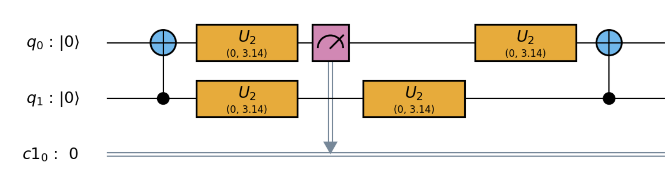
The following circuit is not correctly justified, the first U2 after the measure appears in its own column, rather than underneath the other U2.
Steps to reproduce the problem
qasm = """
OPENQASM 2.0;
include "qelib1.inc";
qreg q[5];
creg c1[1];
u2(0,3.14159265358979) q[0];
u2(0,3.14159265358979) q[1];
cx q[1],q[0];
u2(0,3.14159265358979) q[0];
u2(0,3.14159265358979) q[1];
u2(0,3.14159265358979) q[1];
measure q[0] -> c1[0];
u2(0,3.14159265358979) q[0];
cx q[1],q[0];
u2(0,3.14159265358979) q[0];
u2(0,3.14159265358979) q[1];
 """
from qiskit import QuantumCircuit
qc = QuantumCircuit.from_qasm_str(qasm)
print(qc)
        ┌──────────────┐┌───┐┌──────────────┐┌─┐                ┌──────────────┐┌───┐┌──────────────┐
q_0: |0>┤ U2(0,3.1416) ├┤ X ├┤ U2(0,3.1416) ├┤M├────────────────┤ U2(0,3.1416) ├┤ X ├┤ U2(0,3.1416) ├
        ├──────────────┤└─┬─┘├──────────────┤└╥┘┌──────────────┐└──────────────┘└─┬─┘├──────────────┤
q_1: |0>┤ U2(0,3.1416) ├──■──┤ U2(0,3.1416) ├─╫─┤ U2(0,3.1416) ├──────────────────■──┤ U2(0,3.1416) ├
        └──────────────┘     └──────────────┘ ║ └──────────────┘                     └──────────────┘
q_2: |0>──────────────────────────────────────╫──────────────────────────────────────────────────────
                                              ║
q_3: |0>──────────────────────────────────────╫──────────────────────────────────────────────────────
                                              ║
q_4: |0>──────────────────────────────────────╫──────────────────────────────────────────────────────
                                              ║
c1_0: 0 ══════════════════════════════════════╩══════════════════════════════════════════════════════
What is the expected behavior?
        ┌──────────────┐┌───┐┌──────────────┐┌─┐┌──────────────┐┌───┐┌──────────────┐
q_0: |0>┤ U2(0,3.1416) ├┤ X ├┤ U2(0,3.1416) ├┤M├┤ U2(0,3.1416) ├┤ X ├┤ U2(0,3.1416) ├
        ├──────────────┤└─┬─┘├──────────────┤└╥┘├──────────────┤└─┬─┘├──────────────┤
q_1: |0>┤ U2(0,3.1416) ├──■──┤ U2(0,3.1416) ├─╫─┤ U2(0,3.1416) ├──■──┤ U2(0,3.1416) ├
        └──────────────┘     └──────────────┘ ║ └──────────────┘     └──────────────┘
q_2: |0>──────────────────────────────────────╫──────────────────────────────────────
                                              ║
q_3: |0>──────────────────────────────────────╫──────────────────────────────────────
                                              ║
q_4: |0>──────────────────────────────────────╫──────────────────────────────────────
                                              ║
c1_0: 0 ══════════════════════════════════════╩══════════════════════════════════════
 maddy-tod
All 27 comments
It seems like this example has the same issue (last round of H):

 1ucian0
on 16 Jul 2019
1ucian0
on 16 Jul 2019
The file to examine for the bug is qiskit-terra/qiskit/visualization/text.py
 jwoehr
on 17 Jul 2019
jwoehr
on 17 Jul 2019
I think the error is likely to be in qiskit-terra/qiskit/visualization/utils.py in the method _get_layered_instructions() as I am seeing the bug in both the mpl and the latex outputs too. It is probably an error with the way the layers are being generated rather than drawn.

maddy-tod
on 17 Jul 2019
print(qc.draw(justify='right')) works as expected. left the default and none are broken.
Ditto circuit_drawer. Try:
circuit_drawer(qc, output='latex', interactive=True, justify='left')
circuit_drawer(qc, output='latex', interactive=True, justify='right')
circuit_drawer(qc, output='latex', interactive=True, justify='none')
I have examined the code and have enough of a handle on this that I can fix it .IF. I am sure I knew what is intended by left, right, and no justification. _I do think I understand, but want to be sure._
Can someone please clearly enunciate the definitions?
Furthermore, I don't understand the "expected behavior" in the original report: There are 2 u2 operations on q1 after the cx and before the measure, so shouldn't there be a "hanging" one to right of the stacked u2s and before the measure? And likewise, the "hanging" u2 seems to have moved over to the right of the measure ... is this really the "expected behavior" of diagramming the circuit generated by the qasm code given?
jwoehr
on 3 Aug 2019
print(qc.draw(justify='right'))works as expected.leftthe default andnoneare broken.Ditto
circuit_drawer. Try:circuit_drawer(qc, output='latex', interactive=True, justify='left') circuit_drawer(qc, output='latex', interactive=True, justify='right') circuit_drawer(qc, output='latex', interactive=True, justify='none')
I was wrong, I believe now the only one that appears to be correct is none justification.
jwoehr
on 3 Aug 2019
@jwoehr the justifications are to enable you too see the ASAP/ALAP layouts of the circuit. left means all the gates are drawn in the circuit as far to the left as possible, so the ASAP ordering. right means they are drawn as far to the right, ALAP ordering. none means each gate appears in its own column in the circuit.
The expected behaviour in the top example is that the two u2 gates are stacked on top of eachother, as regardless of the order they were declared in they can happen at the same time.
maddy-tod
on 5 Aug 2019
Okay, thanks, @maddy-tod , I will work on it.
jwoehr
on 5 Aug 2019
The expected behaviour in the top example is that the two
u2gates are stacked on top of eachother, as regardless of the order they were declared in they can happen at the same time.
@maddy-tod, me still confoozed :)
There are 3 u2 circuits in the last stack before the measure in the example given, 1 for q[0] and 2 for q[1].
u2(0,3.14159265358979) q[0];
u2(0,3.14159265358979) q[1];
u2(0,3.14159265358979) q[1];
Are you saying the 2 for q[1] get superimposed, drawn on top of one another, so I only see one of the q[1] ops?
jwoehr
on 5 Aug 2019
See, if I add an id op:
u2(0,3.14159265358979) q[0];
u2(0,3.14159265358979) q[1];
id q[0];
u2(0,3.14159265358979) q[1];
measure q[0] -> c1[0];
etc., it comes out very nicely both left and right justification, as expected, with both u2 operations showing:
left
┌────────────┐┌───┐┌────────────┐ ┌────┐ ┌─┐┌────────────┐┌───┐┌────────────┐
q_0: |0>┤ U2(0,pi/1) ├┤ X ├┤ U2(0,pi/1) ├────┤ Id ├────┤M├┤ U2(0,pi/1) ├┤ X ├┤ U2(0,pi/1) ├
├────────────┤└─┬─┘├────────────┤┌───┴────┴───┐└╥┘└────────────┘└─┬─┘├────────────┤
q_1: |0>┤ U2(0,pi/1) ├──■──┤ U2(0,pi/1) ├┤ U2(0,pi/1) ├─╫─────────────────■──┤ U2(0,pi/1) ├
└────────────┘ └────────────┘└────────────┘ ║ └────────────┘
q_2: |0>────────────────────────────────────────────────╫──────────────────────────────────
║
q_3: |0>────────────────────────────────────────────────╫──────────────────────────────────
║
q_4: |0>────────────────────────────────────────────────╫──────────────────────────────────
║
c1_0: 0 ════════════════════════════════════════════════╩══════════════════════════════════
right
┌────────────┐┌───┐┌────────────┐ ┌────┐ ┌─┐┌────────────┐┌───┐┌────────────┐
q_0: |0>┤ U2(0,pi/1) ├┤ X ├┤ U2(0,pi/1) ├────┤ Id ├────┤M├┤ U2(0,pi/1) ├┤ X ├┤ U2(0,pi/1) ├
├────────────┤└─┬─┘├────────────┤┌───┴────┴───┐└╥┘└────────────┘└─┬─┘├────────────┤
q_1: |0>┤ U2(0,pi/1) ├──■──┤ U2(0,pi/1) ├┤ U2(0,pi/1) ├─╫─────────────────■──┤ U2(0,pi/1) ├
└────────────┘ └────────────┘└────────────┘ ║ └────────────┘
q_2: |0>────────────────────────────────────────────────╫──────────────────────────────────
║
q_3: |0>────────────────────────────────────────────────╫──────────────────────────────────
║
q_4: |0>────────────────────────────────────────────────╫──────────────────────────────────
║
c1_0: 0 ════════════════════════════════════════════════╩══════════════════════════════════
No, this is about the column they are drawn to, they should never be superimposed.
In the example you gave, the right justify is not correct, as the first U2 gate is not in the column as far to the left as it can be. It should be directly underneath the other U2.
right
┌────────────┐┌───┐┌────────────┐ ┌────┐ ┌─┐┌────────────┐┌───┐┌────────────┐
q_0: |0>┤ U2(0,pi/1) ├┤ X ├┤ U2(0,pi/1) ├────┤ Id ├────┤M├┤ U2(0,pi/1) ├┤ X ├┤ U2(0,pi/1) ├
├────────────┤└─┬─┘├────────────┤ └────┘ └╥┘├────────────┤└─┬─┘├────────────┤
q_1: |0>┤ U2(0,pi/1) ├──■──┤ U2(0,pi/1) ├───────────────╫─┤ U2(0,pi/1) ├──■──┤ U2(0,pi/1) ├
└────────────┘ └──────────── ║ └────────────┘ └────────────┘
q_2: |0>────────────────────────────────────────────────╫──────────────────────────────────
║
q_3: |0>────────────────────────────────────────────────╫──────────────────────────────────
║
q_4: |0>────────────────────────────────────────────────╫──────────────────────────────────
║
c1_0: 0 ════════════════════════════════════════════════╩══════════════════════════════════
Now I'm more confused!
In your diagram above, how can the "extra" u2 on q[1] be to the right of the measure? It comes before the measure in the qasm code.
jwoehr
on 6 Aug 2019
It is not directly following the qasm order, it is more looking at the topological order - aka which order the gates have to be executed in to stay consistent with the qasm.
Consider the circuit
qc = QuantumCircuit(2)
qc.iden(1)
qc.h(0)
qc.h(0)
When printed with left justify this follows the same ordering as the code.
┌───┐ ┌───┐
q_0: |0>┤ H ├─┤ H ├
├───┴┐└───┘
q_1: |0>┤ Id ├─────
└────┘
but with right justify the Id gate is shifted to be in the second column.
┌───┐┌───┐
q_0: |0>┤ H ├┤ H ├─
└───┘├───┴┐
q_1: |0>─────┤ Id ├
└────┘
even though the Id gate was declared before the H gates in the code. This is because with right justify we try to draw each gate as far to the right in the circuit, consistent with the code. As there is nothing else on this qubit it is ok to draw the gate in the final column.
Does this make more sense?
maddy-tod
on 6 Aug 2019
Okay, I think I was confused by the measure but since q[1] isn't being measured it doesn't matter where the second u2[q1] appears w/r/t the messure.
jwoehr
on 6 Aug 2019
It seems like this example has the same issue (last round of
H):
@1ucian0 , I recreate qasm for the circuit you illustrated above and test draw left, right, and none with this code:
qasm = """
OPENQASM 2.0;
include "qelib1.inc";
qreg q[4];
h q[0];
h q[1];
h q[2];
h q[3];
cx q[0],q[3];
h q[1];
cx q[0],q[2];
cx q[0],q[1];
h q[2];
cx q[0],q[1];
h q[2];
cx q[0],q[2];
h q[1];
cx q[0],q[3];
h q[0];
h q[1];
h q[2];
h q[3];
 """
from qiskit import QuantumCircuit
qc = QuantumCircuit.from_qasm_str(qasm)
print("draw left")
print(qc.draw(justify='left'))
print("draw right")
print(qc.draw(justify='right'))
print("draw none")
print(qc.draw(justify='none'))
The resulting output is show below. Am I correct that _both_ left and right are incorrect (left for the reason you pointed out above, and right for the positioning of the last h q[3]) while none is correct?
draw left
        ┌───┐                                             ┌───┐
q_0: |0>┤ H ├──■─────────■────■────■────■─────────■───────┤ H ├
        ├───┤  │  ┌───┐  │  ┌─┴─┐┌─┴─┐  │  ┌───┐  │  ┌───┐└───┘
q_1: |0>┤ H ├──┼──┤ H ├──┼──┤ X ├┤ X ├──┼──┤ H ├──┼──┤ H ├─────
        ├───┤  │  └───┘┌─┴─┐├───┤├───┤┌─┴─┐└───┘  │  ├───┤
q_2: |0>┤ H ├──┼───────┤ X ├┤ H ├┤ H ├┤ X ├───────┼──┤ H ├─────
        ├───┤┌─┴─┐     └───┘└───┘└───┘└───┘     ┌─┴─┐└───┘┌───┐
q_3: |0>┤ H ├┤ X ├──────────────────────────────┤ X ├─────┤ H ├
        └───┘└───┘                              └───┘     └───┘
draw right
        ┌───┐                                        ┌───┐
q_0: |0>┤ H ├──■─────────■────■────■────■─────────■──┤ H ├
        ├───┤  │  ┌───┐  │  ┌─┴─┐┌─┴─┐  │  ┌───┐  │  ├───┤
q_1: |0>┤ H ├──┼──┤ H ├──┼──┤ X ├┤ X ├──┼──┤ H ├──┼──┤ H ├
        ├───┤  │  └───┘┌─┴─┐├───┤├───┤┌─┴─┐├───┤  │  └───┘
q_2: |0>┤ H ├──┼───────┤ X ├┤ H ├┤ H ├┤ X ├┤ H ├──┼───────
        ├───┤┌─┴─┐     └───┘└───┘└───┘└───┘└───┘┌─┴─┐┌───┐
q_3: |0>┤ H ├┤ X ├──────────────────────────────┤ X ├┤ H ├
        └───┘└───┘                              └───┘└───┘
draw none
        ┌───┐                                                                      ┌───┐
q_0: |0>┤ H ├──────────────────────■────■────■────■────────────────────────■────■──┤ H ├──────────
        └───┘┌───┐┌───┐            │    │  ┌─┴─┐┌─┴─┐┌───┐┌───┐            │    │  └───┘
q_1: |0>─────┤ H ├┤ H ├────────────┼────┼──┤ X ├┤ X ├┤ H ├┤ H ├────────────┼────┼─────────────────
             └───┘└───┘┌───┐       │  ┌─┴─┐└───┘└───┘└───┘└───┘┌───┐┌───┐┌─┴─┐  │       ┌───┐
q_2: |0>───────────────┤ H ├───────┼──┤ X ├────────────────────┤ H ├┤ H ├┤ X ├──┼───────┤ H ├─────
                       └───┘┌───┐┌─┴─┐└───┘                    └───┘└───┘└───┘┌─┴─┐     └───┘┌───┐
q_3: |0>────────────────────┤ H ├┤ X ├────────────────────────────────────────┤ X ├──────────┤ H ├
Thanks, @maddy-tod
jwoehr
on 13 Aug 2019
Given this source:
OPENQASM 2.0;
include "qelib1.inc";
qreg q[4];
h q[0];
h q[1];
h q[2];
h q[3];
cx q[0],q[3];
h q[1];
cx q[0],q[2];
cx q[0],q[1];
h q[2];
cx q[0],q[1];
h q[2];
cx q[0],q[2];
h q[1];
cx q[0],q[3];
h q[0];
h q[1];
h q[2];
h q[3];
is this now correct for left-justification?
┌───┐ ┌───┐
q_0: |0>┤ H ├──■─────────■────■────■────■─────────■──┤ H ├
├───┤ │ ┌───┐ │ ┌─┴─┐┌─┴─┐ │ ┌───┐ │ ├───┤
q_1: |0>┤ H ├──┼──┤ H ├──┼──┤ X ├┤ X ├──┼──┤ H ├──┼──┤ H ├
├───┤ │ └───┘┌─┴─┐├───┤├───┤┌─┴─┐├───┤ │ └───┘
q_2: |0>┤ H ├──┼───────┤ X ├┤ H ├┤ H ├┤ X ├┤ H ├──┼───────
├───┤┌─┴─┐ └───┘└───┘└───┘└───┘└───┘┌─┴─┐┌───┐
q_3: |0>┤ H ├┤ X ├──────────────────────────────┤ X ├┤ H ├
└───┘└───┘ └───┘└───┘
And ditto the question for this source and output, is this correct left-justification?
OPENQASM 2.0;
include "qelib1.inc";
qreg q[2];
creg c1[1];
u2(0,3.14159265358979) q[0];
u2(0,3.14159265358979) q[1];
cx q[1],q[0];
u2(0,3.14159265358979) q[0];
u2(0,3.14159265358979) q[1];
u2(0,3.14159265358979) q[1]; // or should this u2 appear to left of the measure?
measure q[0] -> c1[0];
u2(0,3.14159265358979) q[0];
cx q[1],q[0];
u2(0,3.14159265358979) q[0];
u2(0,3.14159265358979) q[1];
        ┌────────────┐┌───┐┌────────────┐┌─┐┌────────────┐┌───┐┌────────────┐
q_0: |0>┤ U2(0,pi/1) ├┤ X ├┤ U2(0,pi/1) ├┤M├┤ U2(0,pi/1) ├┤ X ├┤ U2(0,pi/1) ├
        ├────────────┤└─┬─┘├────────────┤└╥┘├────────────┤└─┬─┘├────────────┤
q_1: |0>┤ U2(0,pi/1) ├──■──┤ U2(0,pi/1) ├─╫─┤ U2(0,pi/1) ├──■──┤ U2(0,pi/1) ├
        └────────────┘     └────────────┘ ║ └────────────┘     └────────────┘
c1_0: 0 ══════════════════════════════════╩══════════════════════════════════
A little program to test this and 2 example qasm files representing the circuits we have been discussing.
usage: lay.py [-h] [filepath [filepath ...]]

Test qiskit-terra issue 2802. Usage: python lay.py file.qasm [file.qasm ...]

positional arguments:
  filepath    Filepath to 1 or more .qasm files

optional arguments:
  -h, --help  show this help message and exit
@jwoehr Yes, both those examples are now correct as all the gates are as far to the left in the circuit as they can be
maddy-tod
on 15 Aug 2019
@jwoehr Yes, both those examples are now correct as all the gates are as far to the left in the circuit as they can be
Well, here is the punchline of the joke: That's what the code does when one calls for right justification!
Since none already works, I just have to
- switch
leftandrightinutils.py _get_layered_instructions(), and - make the _formerly-left-now-right_ work correctly.
jwoehr
on 15 Aug 2019
I think the issue is that the layers don't taken into account where the actual gates will be plotted
draw left
        ┌───┐                                             ┌───┐
q_0: |0>┤ H ├──■─────────■────■────■────■─────────■───────┤ H ├
        ├───┤  │  ┌───┐  │  ┌─┴─┐┌─┴─┐  │  ┌───┐  │  ┌───┐└───┘
q_1: |0>┤ H ├──┼──┤ H ├──┼──┤ X ├┤ X ├──┼──┤ H ├──┼──┤ H ├─────
        ├───┤  │  └───┘┌─┴─┐├───┤├───┤┌─┴─┐└───┘  │  ├───┤
q_2: |0>┤ H ├──┼───────┤ X ├┤ H ├┤ H ├┤ X ├───────┼──┤ H ├─────
        ├───┤┌─┴─┐     └───┘└───┘└───┘└───┘     ┌─┴─┐└───┘┌───┐
q_3: |0>┤ H ├┤ X ├──────────────────────────────┤ X ├─────┤ H ├
        └───┘└───┘                              └───┘     └───┘
For example, of the last 3 columns, the first 2 are in the same layer, as all the gates could be executed in parallel. The last column is in a separate layer, as that contains gates that overlap with the previous two columns.
The required change would keep track of where in the column already contained gates, and use that to decide if a gate should stay in that column or not. I think the right justify works in a manner similar to this already.
maddy-tod
on 15 Aug 2019
So that change would still happen in utils.py _get_layered_instructions()?
jwoehr
on 15 Aug 2019
Yes :)
maddy-tod
on 15 Aug 2019
@maddy-tod , I offer apologies for being so dull-witted here, but I find the programming problem trivial and the behaviour specification nearly impenetrable :)
Given the following qasm:
OPENQASM 2.0;
include "qelib1.inc";
qreg q[3];
creg c[1];
h q[0];
h q[1];
h q[2];
measure q[0] -> c[0];
h q[1];
Here is the current behaviour of the various justifications. Are they correct? Can a "rule" be enunciated about the priority of a multibit gate w/r/t a single bit gate, or the priority of a measure over other operators?
justification left:
        ┌───┐┌─┐
q_0: |0>┤ H ├┤M├─────
        ├───┤└╥┘┌───┐
q_1: |0>┤ H ├─╫─┤ H ├
        ├───┤ ║ └───┘
q_2: |0>┤ H ├─╫──────
        └───┘ ║
 c_0: 0 ══════╩══════

justification right:
        ┌───┐┌─┐
q_0: |0>┤ H ├┤M├─────
        ├───┤└╥┘┌───┐
q_1: |0>┤ H ├─╫─┤ H ├
        ├───┤ ║ └───┘
q_2: |0>┤ H ├─╫──────
        └───┘ ║
 c_0: 0 ══════╩══════

draw justification none:
        ┌───┐               ┌─┐
q_0: |0>┤ H ├───────────────┤M├
        └───┘┌───┐┌───┐     └╥┘
q_1: |0>─────┤ H ├┤ H ├──────╫─
             └───┘└───┘┌───┐ ║
q_2: |0>───────────────┤ H ├─╫─
                       └───┘ ║
 c_0: 0 ═════════════════════╩═
Is even justifcation none correct in the above?
Incidentally, the bizarre output of utils.py _get_layered_instructions() as currently defined illustrates how tangled the code really is :)
ops by layer:
:::
    <qiskit.extensions.standard.h.HGate object at 0x7fb44f23f780> [Qubit(QuantumRegister(3, 'q'), 0)]
    <qiskit.extensions.standard.h.HGate object at 0x7fb44f23f4a8> [Qubit(QuantumRegister(3, 'q'), 1)]
    <qiskit.extensions.standard.h.HGate object at 0x7fb44f23f6d8> [Qubit(QuantumRegister(3, 'q'), 2)]
:::
    <qiskit.circuit.measure.Measure object at 0x7fb44f23f3c8> [Qubit(QuantumRegister(3, 'q'), 0)]
    <qiskit.circuit.measure.Measure object at 0x7fb44f23f3c8> [Qubit(QuantumRegister(3, 'q'), 0)]
    <qiskit.circuit.measure.Measure object at 0x7fb44f23f3c8> [Qubit(QuantumRegister(3, 'q'), 0)]
:::
    <qiskit.extensions.standard.h.HGate object at 0x7fb44f23f240> [Qubit(QuantumRegister(3, 'q'), 1)]
I attach again the current version of my little program lay.py to test layer generation and draw output.
lay.py.zip
jwoehr
on 20 Aug 2019
For justification right, the H on q_2 should be on the last time slice, not the first.
 ajavadia
on 21 Aug 2019
ajavadia
on 21 Aug 2019
Question about DagCircuit:
Given the following Qasm source as qasm_src:
OPENQASM 2.0;
include "qelib1.inc";
qreg q[3];
creg c[1];
h q[0];
h q[1];
h q[2];
measure q[0] -> c[0];
cx q[2],q[1];
h q[1];
and then
q_circ = QuantumCircuit.from_qasm_str(qasm_src)
noney =_get_layered_instructions(q_circ, justify='none')
_get_layered_instructions(q_circ, justify='none') simply does a
ops = []
for node in dag.topological_op_nodes():
    ops.append([node]
which comes out like this:
<qiskit.extensions.standard.h.HGate object at 0x7f214a874668> [Qubit(QuantumRegister(3, 'q'), 0)]
<qiskit.extensions.standard.h.HGate object at 0x7f214a874ba8> [Qubit(QuantumRegister(3, 'q'), 1)]
<qiskit.extensions.standard.h.HGate object at 0x7f214a874e80> [Qubit(QuantumRegister(3, 'q'), 2)]
<qiskit.extensions.standard.cx.CnotGate object at 0x7f214a862c50> [Qubit(QuantumRegister(3, 'q'), 2), Qubit(QuantumRegister(3, 'q'), 1)]
<qiskit.extensions.standard.h.HGate object at 0x7f214a862ac8> [Qubit(QuantumRegister(3, 'q'), 1)]
<qiskit.circuit.measure.Measure object at 0x7f214a862dd8> [Qubit(QuantumRegister(3, 'q'), 0)]
- Why does
topological_op_nodes()move themeasureto the end? - Is this behavior predictable and following a rule for all circuits?
jwoehr
on 27 Aug 2019
If you have a look at the DAG generated by the qasm you have given, it can be seen that the measure is independent of the cx and final h so it does not matter where in the list comes in relation to them.
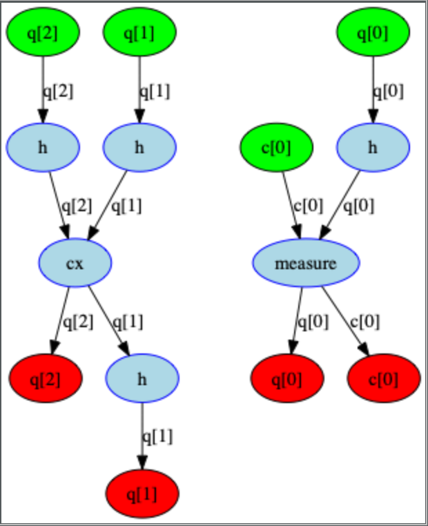
According to the networkx documentation topological sorts are non unique, which means that both the qasm order and the order returned by the DAG are valid (along with many other potential orderings!). We have found that the order the nodes are returned can vary with python versions, but ultimately they are all valid orderings.
maddy-tod
on 27 Aug 2019
Related issues
1ucian0
·
5Comments
 jaygambetta
·
6Comments
jaygambetta
·
6Comments
 kdk
·
4Comments
kdk
·
4Comments
 manoelmarques
·
4Comments
jaygambetta
·
5Comments
manoelmarques
·
4Comments
jaygambetta
·
5Comments
Most helpful comment
@1ucian0 , I recreate qasm for the circuit you illustrated above and test draw
left,right, andnonewith this code:The resulting output is show below. Am I correct that _both_
leftandrightare incorrect (leftfor the reason you pointed out above, andrightfor the positioning of the lasth q[3]) whilenoneis correct?