Prusa-firmware: [BUG] Firmware 3.9.0-RC1 print quality degradation compared to 3.8.1
Printer type - MK3S
Printer firmware version- 3.9.0-RC1
MMU Upgrade - MMU2S
**MMU upgrade firmware version 1.0.6
Describe the bug
Print source: https://www.thingiverse.com/thing:3494496
and explicitly: https://www.thingiverse.com/download:6386081
While printing the above STL sliced with PrusaSlicer 2.20-RC2 and using PETG material works just fine when using the MK3S firmware 3.8.1 (build result on the left), the very same gcode results an awful quality after the printer was upgraded to 3.9.0-RC1 (end result on the right).
Please, see the attached picture.
To Reproduce
Upgrade firmware MK3S firmware to 3.9.0-RC1
and print the above mentioned STL file.
Expected behavior
The print quality should not degrade, compared to previous firmware version.

 nikkolade
All 104 comments
Could you post the 3mf file saved by PrusaSlicer using the same settings you used to print it? Also posting the gcode itself would help so we can have a look.
 wavexx
on 16 Mar 2020
wavexx
on 16 Mar 2020
Sure, here is the 3mf file.
nikkolade
on 16 Mar 2020
And the gcode
gcode.zip
nikkolade
on 16 Mar 2020
Hm... have you tried re-calibrating your linear advance K-value with 3.9.0? I'm not saying the default shouldn't work fine, but I'm curious whether calibrating for the 1.5 K-value makes the issue go away.
 vintagepc
on 16 Mar 2020
vintagepc
on 16 Mar 2020
No, I haven't. What is the proper way to run the linear advance calibration ?
My printer is currently busy for the next 12 hours, but I can certainly try this out after it's idle again.
nikkolade
on 17 Mar 2020
You can find instructions on what Linear advance is and how to calibrate it here: https://marlinfw.org/docs/features/lin_advance.html
You are looking for LA 1.5.
 leptun
on 17 Mar 2020
leptun
on 17 Mar 2020
FWIW, I hadn't paid it much mind but since you are also using PETG... I've noticed my PETG prints are also a little sloppier in terms of strings, sags and zits, but nowhere near the picture levels of bad. I initially ascribed it to wet filament but a fresh roll last night didn't show any improvement, so there may be something to this issue. I'll also try running an LA1.5 calibration for PETG next time I load it up.
PLA's been fine so far.
vintagepc
on 17 Mar 2020
@nikkolade thanks for reporting, this is a serious issue and we must solve it before the 3.9 final goes out.
Could you please do the LA15 calibration test as @leptun proposed? We are especially interested in the "correct" K-factor you get (a photo of the whole print sheet with calibration lines will be great).
 DRracer
on 18 Mar 2020
DRracer
on 18 Mar 2020
I don't know what is the problem with this particular calibration, as I only increased the temp to 210C and changed some filenames, but for some reason the included gcode crashes the printer right after the initial bed calibration. Therefore I was unable to print anything with this test.
I tried a few times from octoprint and from SD-card, didn't matter at all.
nikkolade
on 18 Mar 2020
I used that code/page recently for flex, so the gcode should be okay.
I see you have an MMU. There's a known bug if you try to extrude with IR=1 and FINDA=0, or a runout detected with a "?" on the screen for the filament. (Fix is pending merge)
Try doing a load to nozzle first if you haven't already done so - the gcode does not have the MMU single mode Tx/Tc commands that prompt filament selection.
vintagepc
on 18 Mar 2020
@nikkolade Just tried the gcode on a MK2.5S without MMU and there was no crash. It is as @vintagepc said.
leptun
on 18 Mar 2020
Yes, manually loading to nozzle first allowed the test to be executed.
Of course the PLA-filament I used is clear, so the end result is slightly difficult to see. I can certainly run it again with for example white PLA or some PETG if needed.

nikkolade
on 18 Mar 2020
The calibration is technically filament specific, so you might want to use the orange PETG for the calibration.
leptun
on 18 Mar 2020
Also, you're going to want to run a lot narrower range. Your 0.1 line is already showing overextrusion at the start of the fast section, and it just gets worse. Try something like 0 to 0.2 with 0.02 steps instead. (I think the default range of up to 2 is targeted at bowden setups, which require much higher K values)
What you're looking at here are the transitions from slow to fast and back again - ideally you should have some that are too fat at the start of the fast segment, and some that are too fat at the end, to show you've got some values on either side of the correct one.
You want the most uniform line you can get, it should not be possible to see where the fast travel part starts and ends.
Hope that helps clarify what you're looking at. You might need a few cycles to narrow down the right range of values to test.
vintagepc
on 18 Mar 2020
Ok, yet another test result. Any tuning suggestions after this ?
Although, the numbers are somewhat missing, this one is in the range of 0 -> 0.2
as suggested.

nikkolade
on 18 Mar 2020
@nikkolade looking at your calibration print I'd say the best K factor is 0.08. S far we've been using 0.12 AFAIK.
Now please take your g-code and search for:
M900 K45 ; Filament gcode
Change it to:
M900 K0.08
Save and run a few centimeters of your container print to see if there is any difference.
We'll be doing similar tests at Prusa HQ tomorrow.
DRracer
on 18 Mar 2020
.08 looks pretty good to me - Edit your custom filament g-code for the orange PETG and change the K value for the M900 command, e.g. M900 K0.08
Then try your original print again (be careful you don't revert the K change if you re-open the 3MF file!)
You can probably skip doing the whole print and just cut out a chunk of it or stop a few cm in where the issue would have manifested itself
Edit: Aha, ninja'd by @DRracer :-)
vintagepc
on 18 Mar 2020
Ok, I'll let the printer try again with the modified gcode. Let's see if the end result is equal to FW 3.8.1 this time. I'll let you know latest in the morning.
nikkolade
on 18 Mar 2020
I would definitely use a smooth PEI sheet to determine the K factor. :smile:
 Panayiotis-git
on 18 Mar 2020
Panayiotis-git
on 18 Mar 2020
Ok, the K0.08 value modification improved the end result a lot!

nikkolade
on 18 Mar 2020
Interesting, and good to know.
I'm guessing that's Prusament PETG?
I'll spot check my Overture (AKA former Amazon) PETG tonight and see if I get a similar value or if it's closer to 0.12.
vintagepc
on 18 Mar 2020
@nikkolade interesting result, please let the print finish if possible for detailed comparison with the one printed with FW 3.8.1
Btw. how old is your nozzle - i.e. how much filament did go through (roughly)?
@vintagepc please do a LA15 calibration on your machine too
@wavexx @leptun FYI
DRracer
on 18 Mar 2020
Will do. Current print is finishing in about 20 minutes. Will post pictures of the plate.
vintagepc
on 18 Mar 2020
Results are in. For me, PLA @ 210C (red) comes in best at 0.04, PETG@235 (black) also at 0.08.


I do have a Skelestruder but the gear->nozzle distance isn't as different from stock as it used to be; the 3S revision shortened that a bit; so my values might be a smidgen lower than expected. (FWIW I was running 20 for PLA and 35 for PETG in LA1.0, but those were not calibrated at all and just going off a generic comment that I could drop the Mk3 values by ~10. )
vintagepc
on 18 Mar 2020
The print is now complete and there seems to be still a big difference with the latest 3.9.0-RC1 and the older 3.8.1 versions. The print looks much better from the front after the K-value change.
However, the lefthand side of the print is still much more worse than the other sides.
The filament is Prusa PETG, not prusament. All my filaments have been dried every once in a while, so they are not wet. The printer itself is originally of MK3 model and it has been delivered on December 2018. It has not been used heavily though as there has been occasionally months between the prints. I quess 3-4 complete rolls and half a dozen non-empty rolls.

.

nikkolade
on 19 Mar 2020
@nikkolade oh, this is interesting - it looks like some error is being accumulated after those many retractions.
@wavexx what do you think?
DRracer
on 19 Mar 2020
I don't think that's K value related anymore. The parts that are not clean (esp. right under the thicker bands) all have a very "melty" look to them, like there is not enough cooling. Notice how it "shrinks" inwards instead of just being extra ooze attached to the exterior of the part like previously.
This seems even more likely given the front of the print is reasonable and the sides have issues
@nikkolade Has your filament been sitting out in the open for a while? PETG absorbs moisture and that can produce symptoms like we are still seeing. How much time elapsed between the print you made on 3.8.1 and the reprint with the RC firmware?
vintagepc
on 19 Mar 2020
I did the two prints after each other, ~8h difference. The latter one was using the FW 3.8.1 and the same roll of PETG, so the FW3.8.1 print should have had the quality issues, if it would be caused by moisture in the filament.
I have a food drier and this particular roll has been dried 2 days ago. After drying, the filaments are kept in a ikea samla plastic box that has been "sealed", together with silica gel pouches (a lot of them, also recently dried).
I bet that I can print again one of these containers with the older 3.8.1 and using the same filament roll and they will still look good.
nikkolade
on 19 Mar 2020
@wavexx Does LA1.5 slow down acceleration even when just Z and E moves are done? Maybe these are slower with LA1.5 compared to LA1.0 which didn't take Ejerk into account.
leptun
on 19 Mar 2020
I'll give part of the print a go today on my own setup to see whether I also have the same artifacts even with a corrected K-value. It won't be completely conclusive but very informative as to whether it's heat related.
Edit: Hooboy, this print is a good retraction torture test.... :-)
vintagepc
on 19 Mar 2020
Print still in progress, but quality is indeed abysmal. Part of the problem is the thin vertical sections flex quite a bit, which also results in uneven sides and stringiness. Will edit in a picture when it finishes. I am experimenting with tuning cooling/temps to see if I can get an improvement.
vintagepc
on 19 Mar 2020
Update:
I think this is indeed compounded by a cooling issue. Not sure why that would have changed from 3.8 to 3.9 though.
I printed a shorter part but the results are similar. It looks like the worst parts of the print for me are those that are shielded somewhat by other print parts, whereas the best ones are most exposed to the cooling fan airstream.
Part as printed on the bed:

I made tuning adjustments as the print progressed:
-> No changes until halfway up the first course of spindles
-> Dialled back temp to 230 (from 235), increased fan setting to 110 (from 76) halfway up the first stage
-> For the second stage of spindles, I dialled up the fan to 200, flow to 95%
Picture of the cooling duct:

Additional part photos:


vintagepc
on 19 Mar 2020
It always looked like a cooling issue to me more than LA itself, but given a higher K factor will lead to slower jerk the issues are probably connected. These thin features will overheat quickly.
The gcode is resliced already at E-jerk=4.5, which looks good. Did you change it yourself?
I also see Tx/Tc gcodes which I didn't see before.
To respond also to @leptun, any move which is not involving extrusion is not changed by LA (so wipes/jumps shouldn't be affected).
For the stock Prusament Orange I do use K=0.12 at the default temperature of 250C.
For the "Prusa clear PETG" which I use at 240C ("generic pet" profile) I've set up a K=0.13 even. It depends a bit.
I'd love to try this, but I'm currently restricted in movement for this covid19 thing, so huuh, it's a bit hard to test stuff. I don't have PETG at the moment :/
I'd try two thing out of my mind:
reduce retraction length: the default is 0.8, I'd go for 0.5. I know it sounds counter-intuitive, but if the LA factor is properly tuned there's generally a lot less pressure left at the end of the extrusion. Some retraction is still needed to avoid ooze, but reducing it will reduce the time spent on small features like these.
bump E-jerk even higher. In machine-limits, in "maximum jerk E" try to increase to something much higher, like 8. This is not a solution in itself, but it will increase acceleration overall which is useful to see if results in an appreciable difference.
wavexx
on 19 Mar 2020
reduce retraction length: the default is 0.8, I'd go for 0.5. I know it sounds counter-intuitive, but if the LA factor is properly tuned there's generally a lot less pressure left at the end of the extrusion. Some retraction is still needed to avoid ooze, but reducing it will reduce the time spent on small features like these.
FWIW my default retraction is 0.4. I'll up the E-jerk in the .gcode file and reprint to see what happens.
Also, I had similar strings and crap on larger full-bed prints where localized part heating should not have been an issue.
vintagepc
on 19 Mar 2020
Not sure how it can help, but I just gave a try to the K-factor calibration with Stratasys Blue ABS-M30. I got the best result at 0.04 on a MK3s.
 Kachidoki2807
on 19 Mar 2020
Kachidoki2807
on 19 Mar 2020
As I happened to have some use for an additional silica gel container, I printed with the same original PETG filament roll & FW 3.8.1 the following items (75mm size this time) and the end result is very good in my opinion. There is certainly some tuning to be done for the upcoming FW version before it will produce the same quality out of the box.


nikkolade
on 19 Mar 2020
No improvement changing the E-jerk to 8.
I had a go at trying to back out LA1.5 from the current RC to confirm if it is the origin of the difference. Alas this introduces a few compile errors I'm not easily able to resolve without slogging through the history of those changes.
vintagepc
on 19 Mar 2020
On Thu, Mar 19 2020, vintagepc wrote:
I had a go at trying to back out LA1.5 from the current RC to confirm
if it is the origin of the difference. Alas this introduces a few
compile errors I'm not easily able to resolve without slogging through
the history of those changes.
You can set K0 to disable LA completely. This will generate some
overextrusion on the corners, but this would help determining if LA can
be the source of the issue
wavexx
on 19 Mar 2020
Well, the simplest solution... :tada:
Anyway, print in progress. Looking good so far...
vintagepc
on 20 Mar 2020
Well, I think these pictures speak for themselves. (I cut off just a segment to speed up the testing)


vintagepc
on 20 Mar 2020
Is this comparable to 3.8.1 all-else being equal?
wavexx
on 20 Mar 2020
I don't have a 3.8.1 reference to compare it to but it looks very much like the OP's 3.8.1 print in terms of stringing/quality. Slicing settings are identical to the lower half of my other print; only difference here is M900 K0 instead of K0.08
If it's beneficial I can compile 3.8.1 for my printer and try the same g-code tomorrow. (Can't use official release as 3.8.1 doesn't have #2306 and my setup seemed to hit that last time I flashed back.)
vintagepc
on 20 Mar 2020
I'm going to try to reproduce the issue (or at least try to see if I can notice a difference) using regular PLA. At this point it's either still too much e-jerk influence or there is some odd overextrusion going on that hopefully I should be able to spot with PLA
wavexx
on 20 Mar 2020
That sounds quite possible - Observing the previous prints most of the stringing and junk is from PETG that has crept up the sides of the nozzle and is being dragged around partially sticking to fresh bits that get laid down.
vintagepc
on 20 Mar 2020
Indeed, once some petg starts sticking to the sides of the nozzle it's going to stick it everywhere until a long extrusion cleans it all up (in this case the rings)
wavexx
on 20 Mar 2020
Yeah, and that's with a Ni-plated nozzle too, so it strings off in chunks more easily than brass.
Overextrusion certainly explains the meltiness, since if you're adding extra plastic, you also add more heat that needs removing - which is why cranking up the fan helped quite a bit. The test part wasn't flexing nearly as much while the spindles were printing.
Edit - if you don't have PETG and PLA doesn't reproduce it... maybe flex, if you have some? I was having terrible issues getting a clean print out of that too... which, in retrospect could be related to the same issue, since one of the things I tried was setting up an LA value...
https://forum.prusaprinters.org/forum/original-prusa-i3-mk3s-mk3-how-do-i-print-this-printing-help/suggestions-for-printing-this-in-flex/#post-200217
Don't hesitate to let me know if you need me to test anything. I'm also stuck at home and have an ample stash of filament. :-)
vintagepc
on 20 Mar 2020
In the early days of the LA1.5 for the Mk3 I also notices some cases where overextrusion would occur. It’s mostly with really small segments.
The place I encountered it was with some infill that was filling a small gap between perimeters on the first layer. This kind of overextrusion will most likely cause degradation in quality. Please note that it manifested a long time ago and the issue is probably fixed in this case, Also, I was testing Simplify3D for this.

I also think that the “corners” of a solid infill (when it finishes and makes smaller segments) got worse with LA1.5. This is a recent print, so it's the latest LA1.5 implementation. (colored with blue in the picture):

leptun
on 20 Mar 2020
@wavexx Was the K0 compatibility issue fixed or does it still lock to one value or another? It would be best if all these tests were done without this kind of issue since it would most likely create false results with calibrations.
leptun
on 20 Mar 2020
@wavexx Was the K0 compatibility issue fixed or does it still lock to one value or another? It would be best if all these tests were done without this kind of issue since it would most likely create false results with calibrations.
Is there an explicit # for this issue? I opted to use K-1 as a manual "reset". The reset is still done between SD prints, and I would love to implement "print timers" to have an extra hook to reset stuff between prints when using a host (see https://github.com/prusa3d/PrusaSlicer/issues/3724)
K0 still disables LA, but without the mode reset. The reason is that slicer++ (supermerill's fork) allows to customize the K factor by fill-type, so for example you can decide to disable LA during infill. Resetting the mode on K0 could introduce random swaps during the print, which I think is worse.
wavexx
on 20 Mar 2020
If the gcode starts with a K0 and then swithches to another value, will the compatibility be locked because of K0 or will it switch accordingly when K0.01 (LA1.5) or K5 (LA1.0) are seen later?
leptun
on 20 Mar 2020
Mode is decided on the first non-zero value seen. I've been thinking a lot whether adding an explicit "set mode" flag would be a good idea or not, given marlin has none :/
wavexx
on 20 Mar 2020
@nikkolade just a short notice - interestingly, we haven't been able to reproduce you issue so far, we have multiple prints from PETG coming out beautifully in FW 3.8.1 and 3.9.0-RC1, i.e. LA10 and LA15 - directly from your G-code.
I'm not saying there is no issue (there obviously is at least on your and @vintagepc 's printer), we are still searching. Any even minor notice/comment may help.
DRracer
on 25 Mar 2020
Ok, this is baffling new to me. Could there be something in my old printer that is different compared to your's ? I just checked and my printer has been delivered on Dec 2017 as an (early) MK3. It has been updated later on to MK3S and I have added the MMU2S unit at the same time.
I really don't understand, how otherwise my printer could have issues with the 3.9.0-RC1 FW, while your test machines work fine. After all, with the FW 3.8.1, my printer works just nicely and produces good results. Has there been some updates in the HW afterwards, that make the newer models print with better results ... ?
I assume that you have used a similar printer with a textured sheet in at least some of the tests ... ?
nikkolade
on 25 Mar 2020
Interesting. My own printer was received early 2019, with a Mk3S & MMU2S update as well.
I will see if I can do some more experimenting today to try to identify what is going on.
@nikkolade I'm guessing you have a completely stock printer? If yes, that likely eliminates any of the modifications on mine as interferents.
Can you weigh both of your prints to see if there's an appreciable difference in weight between the good one and the bad one? That might help narrow down whether it's an overextrusion issue or primarily a heat issue.
vintagepc
on 25 Mar 2020
Yes, my printer is completely stock. I did add the updated MK3S (latest github models, compared to originals from 2017) Y-belt printed parts a few weeks ago though.
nikkolade
on 25 Mar 2020
OK. To give a complete rundown on my mods:
-> 0.9 degree steppers on X/Y
-> Skelestruder (3.5:1 gear ratio).
-> Firmware is stock + #2526 + #2499 + #2508 + #2473 + #2464 + #2201 (basically all my own open PRs except for the first one)
There are also a few minor load distance tweaks to correct the MMU behaviour with the skelestruder, but nothing that impacts anything other than load/unload.
Edit: I see from the original pictures we both have LACK enclosures. That could certainly exacerbate the issue if it is heat related (but still doesn't explain why things changed across versions)
vintagepc
on 25 Mar 2020
I think I've just confirmed that this is definitely overextrusion:
- I sliced a small part of the offending model that takes about 30 min to print.
- Sliced G-code.
- Edited code to change to K0, saved as a separate file. All other contents identical.
- I cut two identical 1m lengths of filament.
- Used the first to print with M900 K0. 166 mm of filament remaining after the print completed.
- Loaded the second and printed the file with M900 K0.08. 54 mm of filament left after it completed.
So enabling linear advance pushed an extra 112mm of filament (>10%, or, 269mm^3) of plastic into the model. I'd say that is well outside the measurement error which I'd expect to be give or take 10mm (the remaining plastic in the melt zone from load/unload between prints)
Edit: I should note the PS filament consumption estimate was 0.82m, with an observed value of 0.835 is basically within the expected error (significant digits and melt zone)
vintagepc
on 25 Mar 2020
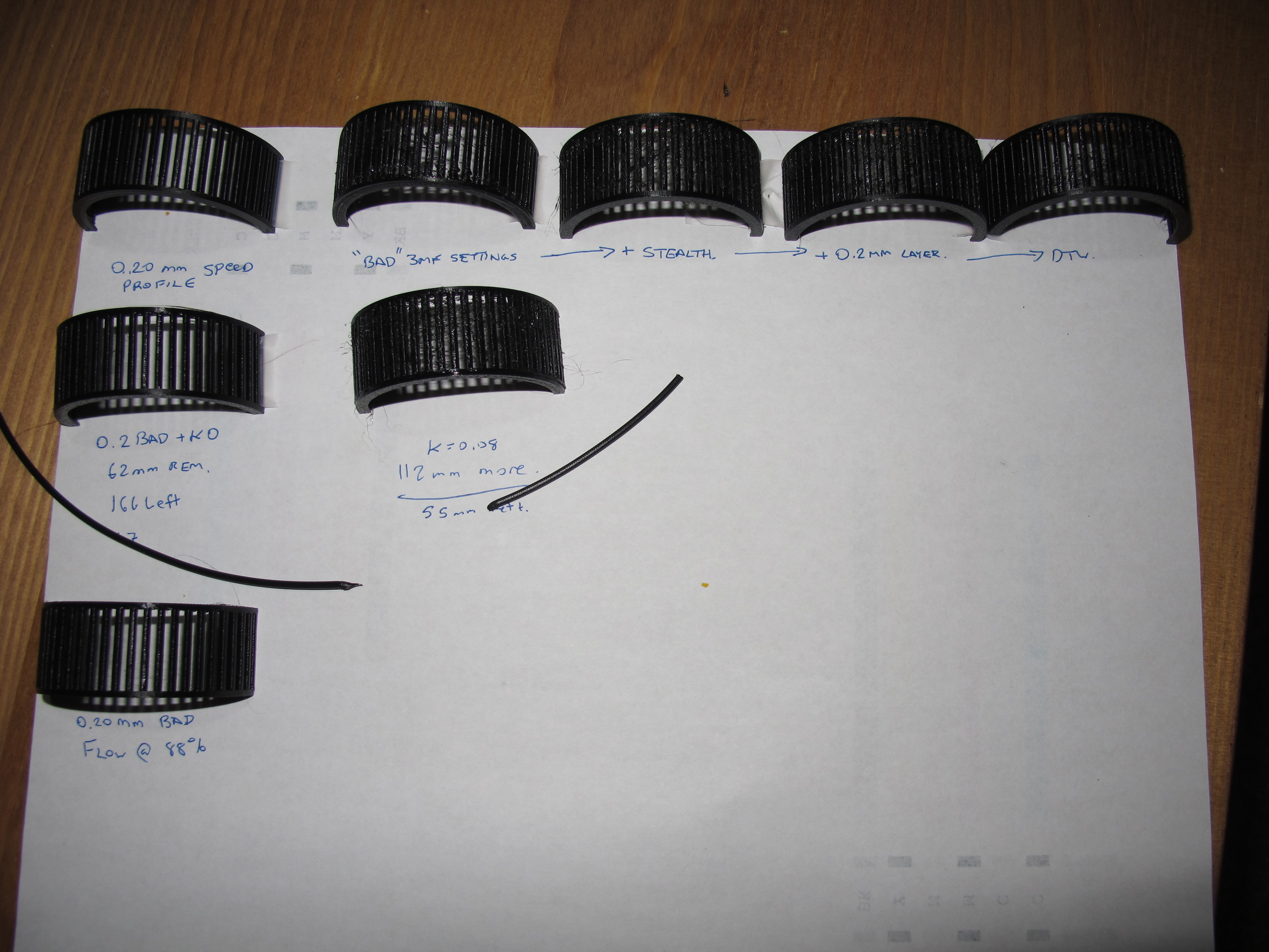
Further update - I ended up getting a good print with a different speed print profile with LA1.5 enabled. It was probably still overextruded (did not do the filament length test on it, can do so if desired) but I was printing perimeters at a much faster rate and at 0.2mm layer height. Top left in the images. The spindles look wider than the "correct" ones.
Reversing the overextrusion calculation and running the "bad" print gcode with a flow rate of 88% produced a good print too. (Bottom left)
I think that means that this particular combo of part and print settings just makes the issue show up particularly well, owing to solid geometry, lower layer height, and a material that stays soft and gummy quite a while.
(Top row is various parameter tweaks based on the working LA slice I was experimenting with, middle row is the overextrusion test from the previous post, bottom row is the reprint at 88% flow)
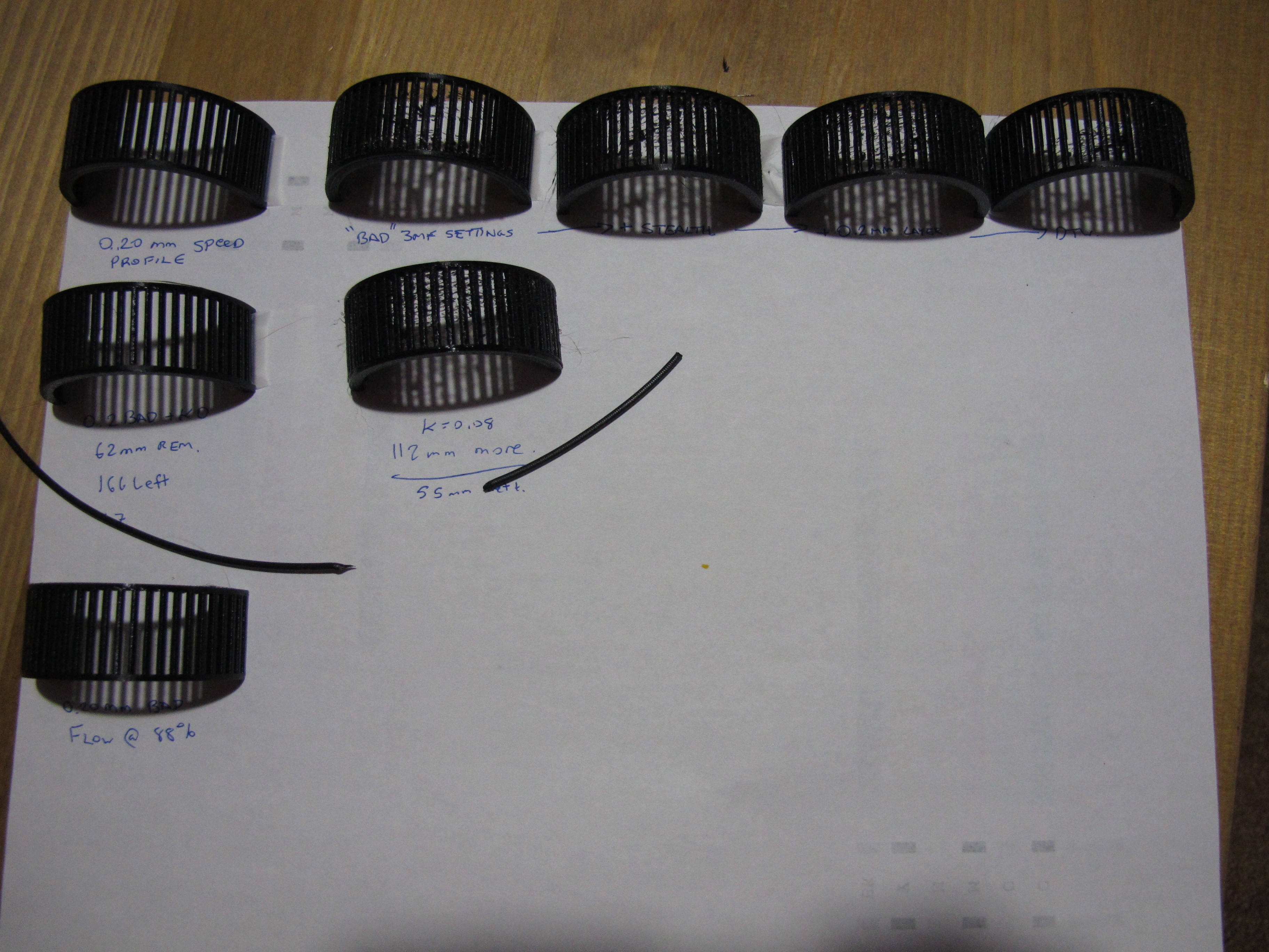
vintagepc
on 25 Mar 2020
I think we have a winner - LA is not working properly on retractions/deretractions.
Disabling retraction results in a reasonably good print, barring the sort of stringing you'd expect from such a setting - but not the overextruded melty mess we are observing in other cases.
I browsed through the code and I suspect there is cumulative error creeping in from the asymmetry of retractions and de-retractions, where negative extruder moves are not compensated, but forward moves are.
It appears to be constant and not related to retraction distance, my default is 0.4, and changing to 0.2 and 0.8 did not appear to make the result any better or worse than 0.4
vintagepc
on 26 Mar 2020
@vintagepc exellent analysis, good job
We have been able to simulate similar results with an MK3S with "MMU" extruder. A "normal" machine doesn't do this.
Probably rising the E-jerk beyond limits (say 20) can also solve the problem, probably the retractions were fine-tuned in previous FW's with respect to the inaccurate material flow and mechanical properties of the extruder.
DRracer
on 26 Mar 2020
Iiiiiinteresting - now I'm curious what it is about the MMU addition that makes it so much worse - especially since it doesn't seem like that should (in theory) alter any of the LA behaviour.
At least in my case I'm not slicing with an MMU profile; I'm slicing with a standard profile that requires manual load-to-nozzle first
Edit: For kicks I tried printing the same model with the MMU disconnected (printer thinks it is a MK3S)- no change, still overextruding.
vintagepc
on 26 Mar 2020
It might not have anything to do with the MMU extruder after all. I did some testing and came to the conclusion that this is a bug in the LA1.5 algorithm.
I created a gcode which should retract+wipe and unretract for ~15s. With K0 it behaves as expected, but with K45 it starts drifting wildly.
Here are videos with the gcode in action:
K0: https://photos.app.goo.gl/oa5ifCEY2mK5Mtfx7
K45: https://photos.app.goo.gl/mcJn5DuAAE2Y4hzg7
Over time, the drifting adds up and results in overextrusion/underextrusion.
leptun
on 27 Mar 2020
Out of curiosity, does it improve if you make retractions symmetric? (e.g. disable the code that cancels LA calculations for negative E moves)
Still feels weird to me to account for compression of filament in one direction but not account for decompression in the other.
Edit - I agree - it'd be weird to be specific to the MMU extruder design since I am still seeing it despite running a third party design myself- which has no filament path alterations for MMU support.
vintagepc
on 27 Mar 2020
@vintagepc I'm not the author of the LA1.5 code. @wavexx Should be able to help us in this regard
leptun
on 27 Mar 2020
Sure, that's fair. It looked like it'd just be removing the if delta_mm[E_AXIS]>0 in the relevant block in planner but I also am not intimately familiar with that area so I could be very wrong ;-)
vintagepc
on 27 Mar 2020
That and maybe also e_D_ratio. But I don't really know.
leptun
on 27 Mar 2020
yeah, I noticed the comments in that area that it might also have issues with retraction lengths <~0.2mm.
But I'm really annoyed I can't do 35mm wide extrusions with my 0.4mm nozzle 🤣
I did also play with Z-hop a bit since retraction =0 also disables z-hop (and it looks like there's a chance for interference there with combo z moves in cases where the planner might combine moves. I didn't get any change boosting Z-hop to 0.8 to get it on the other side of that threshold in the C
vintagepc
on 27 Mar 2020
Would you mind sharing the exact model for this? I know I could just cut it out of the original, but it makes it easier to compare exact results and I'd like to run a few prints :P
I've been looking at this for some days. It is indeed an overextrusion which is something I wouldn't have expected (!), but it actually caused by the wipe move in this case. The original LA and LA1.5 never handled travel/retraction moves, and at least in theory this is because they don't need to do so. This was done differently in the LA found in the MK3, which used a slightly different approach that being fully symmetric didn't have this issue.
The idea in LA is that it should be a zero-sum game: we aim to equalize the pressure in the nozzle according to the speed of the segment. If we end the extrusion on a full stop, or a retraction, the calculated pressure at the end of the segment _will_ be zero and no overextrusion is done (the opposite usually happens).
There _is_ a problem however on a zero-extrusion segment which happens to be in-line with the previous extrusion, thus maintaining momentum. This is currently ignored, but even if we disable the check it would be miscalculated later in the planner. We currently assume that the pressure is lost in this case, as it's normally the case for travel moves, but it's definitely not if the nozzle is kept pressed on the surface as done here. It's also not easy to add back as efficiently as I hoped, because in the end the E axis is still tightly coupled to the entire move, with LA just being slapped on top.
It's also interesting to say that with LA you can have consistent "overusage" of material (I don't really want to say overextrusion) for a couple of reasons. The obvious one is travels or stalls. If we can detect the nozzle has lost pressure, we re-pump material into it on a subsequent move anyway which is usually the right thing to do: a blob on the nozzle will not be dragged along the path of the extrusion, it's just going to ruin the print. You really need more material _within_ the nozzle.
The second is that we cheat a lot in the stepper code. LA ticks are scheduled on a "best effort" basis to avoid skipping and/or degrading the regularity of all the over moves. Especially at fast accelerations with a geared extruder the timing can be _really_ tight, and we do sacrifice a step or two in a segment if needed. This is usually always balanced by it's relative deceleration though, so the cumulative error should be minimal.
wavexx
on 4 Apr 2020
Sure, here you go!
Interesting explanation. I had a sense this would be well above my pay grade to suss out... at least, without a deeper understanding of the real-time parts of the system :-) .That also explains the issue I was running into with my flex print where I'd attempted to set up LA for the material. Things went south very quickly once there was a "step" on the inner wall that caused gap fill, hop over the recess, and then more gap fill. Add in a K-value of 1.2 and you're on your way to blob-ville.
I'm actually kind of curious how you begin to debug something like this, at least in terms of stepping through the code while it's running. I've done similar stuff at work and there are all kinds of considerations w/r/t breakpoints in code that has time constraints...
Seems like this is a magical model that is a hat trick for demonstrating the issue - pathing like you describe, thin parts that are solid, and also don't handle heat build-up well.
Would this have been impacted by the "wipe while retracting" setting? I tend to slice with it off given that a functioning LA cal makes it unnecessary, but based on the description I have to wonder if I'd have seen it had I left it checked, since that's the default.
vintagepc
on 4 Apr 2020
Sure, here you go!
Thanks you so much! Your analysis was invaluable!
Things went south very quickly once there was a "step" on the inner wall that caused gap fill, hop over the recess, and then more gap fill. Add in a K-value of 1.2 and you're on your way to blob-ville.
This is where LA1.5 comes into help and really shines!. Tune down E-jerk. When LA is enabled, you can consider E-jerk as the "compression speed" of the material. It will still be calculating the compression you requested, but the speed at which the target compression is attained can be limited to whatever you need.
Rigid materials can usually have an E-jerk which is defined by the limits of the stepper, but with soft materials it can become an additional tool
I'm actually kind of curious how you begin to debug something like this, at least in terms of stepping through the code while it's running. I've done similar stuff at work and there are all kinds of considerations w/r/t breakpoints in code that has time constraints...
Heh, I'm not joking that I usually add a couple of print statements to where I think the problem is, and go take a walk (when I could!) to think more about it. I have no debugger for the avr, and I cannot currently use my scope due to the lockdown, so ... not the best :P
Seems like this is a magical model that is a hat trick for demonstrating the issue - pathing like you describe, thin parts that are solid, and also don't handle heat build-up well.
This is fascinating to me, also because if we didn't have the MK3 implementation of LA I'm pretty sure this would have never came up (you would probably just assume the issue as a fact!).
Would this have been impacted by the "wipe while retracting" setting? I tend to slice with it off given that a functioning LA cal makes it unnecessary, but based on the description I have to wonder if I'd have seen it had I left it checked, since that's the default.
It really depends on what slicer emits in this case, I'm not sure
wavexx
on 4 Apr 2020
Thanks for the follow-up. Every time I think I've found all the knobs and settings to twiddle with, someone throws me a shovel so I can dig myself even deeper :) (though in reality, the good ship hope kinda sailed as soon as I started poking at the firmware... :rofl: )
Code analysis is fair game, and of course we all fall back to printf debugging when we have to. I was curious whether there were additional secrets; I have an ATMEL ICE here which might be of use for that sort of stuff, but never shun the tried and true.
AFAIK with "wipe while retracting", all P'licer does is essentially add a little swirl at the end of the extrusion to smush around any ooze and iron it out. (Think whipped cream flourish?) Seems that would break the situation where the travel segment is in-line with the LA segment.
I'm in the middle of testing and modelling a print for the contest right now so I've got PLA loaded. But I might give that a test for kicks once I get back to PETG.
vintagepc
on 4 Apr 2020
The main issue with debugging a RT system is that most of the time you cannot really stop the system, except for very rare cases. In most of the cases tracing is the only option, and you have to be very selective to avoid slowing down the system and introduce a _new_ variable into the game. For example, stopping cpu while the heater is active is not a good idea for obvious reasons, but you need that heater on if you're extruding. Similarly you cannot really stop the motion system either, because a hard stop would in most cases just skip and fail to recover later. That being said, having a state dump at specific time points would be a godsend from time to time, I'm not sure if the ICE can be used for this fast enough.
wavexx
on 4 Apr 2020
At that point I would probably start thinking pretty seriously about hardware simulation. Has that been considered? If not I may have a casual tinker to see what can be accomplished in that regard.
vintagepc
on 4 Apr 2020
At that point I would probably start thinking pretty seriously about hardware simulation. Has that been considered? If not I may have a casual tinker to see what can be accomplished in that regard.
I think there would be a business opportunity there =), it's absolutely non-trivial.
To bring back the discussion on topic, which settings did you use for the sliced model? The original gcode was the ".3 quality" with a ".6 nozzle", but re-reading everything right you're also printing with a .4. But the .2 speed profile seems "fat", but good.
I'd like to get the worst result for a .4 nozzle :P
wavexx
on 5 Apr 2020
Well, the bootloader works... :rofl:
Here's my g-code, you should be able to import it into P'licer to get the settings as used. Note if you reslice you might need to edit the startup gcode as there are a few undefined (M914) and specific-to-me (M907 E400) calls.
vintagepc
on 5 Apr 2020
@vintagepc that looks awesome! What are you using for the simulation?
leptun
on 5 Apr 2020
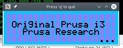
I started mucking around with SimAVR. There'll be some work to define the various parts and connections, but seems like it's not to wild an idea. I'm having fun tinkering with it from an educational perspective; I'll be sure to share if it gets anywhere interesting/useful.
Unfortunately loading the main firmware doesn't do anything yet, probably because I haven't defined anything but the LCD and it's either expecting an answer from the SPI flash or thinks reset/PP is triggered.
vintagepc
on 5 Apr 2020
@vintagepc
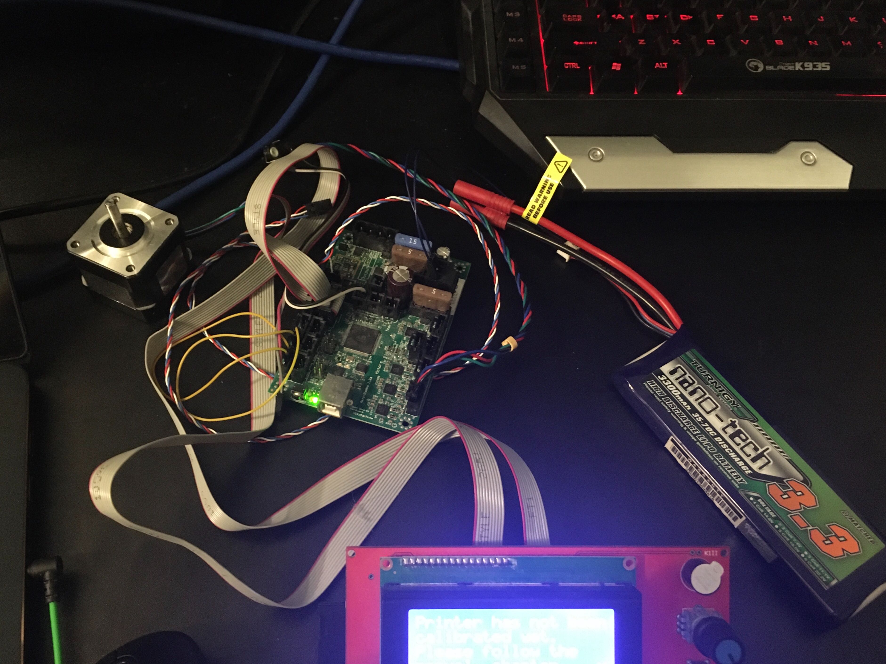
My "simulator"... Almost portable 😆
leptun
on 5 Apr 2020
I started mucking around with SimAVR. There'll be some work to define the various parts and connections, but seems like it's not to wild an idea. I'm having fun tinkering with it from an educational perspective; I'll be sure to share if it gets anywhere interesting/useful.
Even if we cannot do much with it, just faking the peripherals enough to let FW think it's running for a while could still be super-useful. As we were discussing with @leptun, this could help finding the cause of very odd issues and crashes which are likely due to memory corruption.
wavexx
on 5 Apr 2020
absolutely, it opens up a world of possibilities in that regard (easy memory inspection/validation, scripted automated tests of certain conditions (e.g. repeated PowerPanics)... and of course, you can halt it at any time without actually melting your heater because the PWM is stuck on :)
And yeah, I define "useful" as anything close to functional. The beauty of it is that despite how complex the whole system is, it's still just a bunch of individual parts each doing their own thing.
vintagepc
on 5 Apr 2020
So I ran your gcode on my MK3S with some prusament petg (the orange one) and I'm comparing to some other ones I have.
At least with this material, using the .15/.2 quality and speed profiles (so default params) I see thin strings, but nothing too bad.
Using yours it starts similar (similar amount of thin stringing in general), but then I noticed the pillars start to wobble heavily towards the top, and this is when quality degrades very quickly. In my case it detached on one side, so I'm re-running it again.
Did you notice this effect as well, or something different?
wavexx
on 5 Apr 2020
Yes, that is one of the observations I had made.
Edit: Might be insightful to do the same test I did, that is, cut two pieces of filament slightly over 1m in length, and use that to look at the volume of material being extruded.
vintagepc
on 5 Apr 2020
So I ran through some different trade-offs, and came to this:
https://github.com/wavexx/Prusa-Firmware/tree/la15_chained_wipes
Before I make a PR, I'd love some feedback.
I see an improvement in both your "bad" test, as well as a re-sliced model with .15 layers. Stringing is reduced and the pillars look very consistent, however at least using PETG there are still tiny whisps which very in quantity just by reprinting the same model twice. I'd say this is consistent with what I would expect - but I've been wrong before ;)
wavexx
on 9 Apr 2020
Sure, I'll take it for a spin tomorrow!
vintagepc
on 9 Apr 2020
It does look quite good- I don't have any 3.8.1 references, but the surface finish is perfect, and the stringing is about on par with the better results I've gotten for this particular model. It was worse than those for my default K of 0.08 but improved when I tried 0.12 (which makes sense, since this altered the K handling slightly it means a different value might now be optimal).
vintagepc
on 9 Apr 2020
Printed on my stock (no hardware changes) Prusa MK3s with Firmware version
commit 02a36c498cfb087fc4d1e470a7490d08a10484a5 (HEAD)
Author: Yuri D'Elia <[email protected]>
Date:   Wed Apr 8 22:49:48 2020 +0200

 3d-gussner
on 10 Apr 2020
3d-gussner
on 10 Apr 2020
@vintagepc I pushed one last change which again covers some even rarer corner cases. I re-checked this model and I get consistent results with the previous version. I was only able to see a minor difference in a synthetic test that starts extrusion mid-flight (something at least prusa-slicer and slic3r never does).
But if you have filament to spare, I'd love an extra test :P
Mostly to see if you see any difference at all with random models.
wavexx
on 12 Apr 2020
I have a number of items on the to-print list; I'll merge your changes to my local build and use it during the coming week :+1:
vintagepc
on 12 Apr 2020
3d-gussner
on 15 Apr 2020
Been waiting for this to be resolved to try LA1.5. To be clear, do I need to change anything in the slicer to make use of this or will my existing slicer profiles be recognised as legacy and translated by the LA1.5 firmware?
 Makhaira
on 29 Apr 2020
Makhaira
on 29 Apr 2020
Old gcodes are converted automatically. You don’t have to change anything. Slicer profiles will be updated after the final release (hopefully 2 weeks from now)
leptun
on 29 Apr 2020
My 2 cents: I dialed in the K-factor for PETG (with marlin LA 1.5 pattern) and observed a decrease in quality compared to LA 1.0 as well. Most notably, corners were sometimes massively underextruded. To the extent that there were holes in them.
Also, I noticed that the k-factor sensibility has shifted by a factor of 5 or more. What used to be 60 (in LA 1.0) now is around 0.1-0.15.
On another note: Why dont you use a different parameter for LA1.5, like M900 L0.12? Less confusion and error-prone
 apphead
on 29 Apr 2020
apphead
on 29 Apr 2020
We can't switch to another letter since the Marlin test pattern only uses K as the K factor :(
leptun
on 29 Apr 2020
Also, the two ranges don't overlap. Anything over ~15 has to be LA1.0, anything under ~2 (unless you have a bowden system) is 1.5
vintagepc
on 29 Apr 2020
LA1.5 is < 10
LA1.0 is >= 10
leptun
on 29 Apr 2020
I stand corrected. I was going from memory and the thresholds I saw in earlier code. (I do know that it was <15 but in reality values over 2 don't make a lot of sense for most cases, especially stock MK3s)
vintagepc
on 29 Apr 2020
@nikkolade please contact me via email, we'd like to reward you for helping us fixing this issue.
DRracer
on 27 May 2020
Ok, yet another test result. Any tuning suggestions after this ?
Although, the numbers are somewhat missing, this one is in the range of 0 -> 0.2
as suggested.
I haven't seen this calibration method yet. Can someone point me to a URL where I can read more about it? THX!
 scuba840
on 28 May 2020
scuba840
on 28 May 2020
https://marlinfw.org/docs/features/lin_advance.html
It was linked in the first few posts.
vintagepc
on 28 May 2020
Hello!
Maybe interesting: with the great help of @3d-gussner, I created a little document where in PrusaSlicer to find the values for the linear advance calibration website and a little example how to use it ...
 mmuellerphoto
on 29 May 2020
mmuellerphoto
on 29 May 2020
@mmuellerphoto very helpfull. I saw a preliminary version of this PDF a couple of days ago. This would be a nice addition directly to prusa help.
DRracer
on 29 May 2020
@mmuellerphoto very helpfull. I saw a preliminary version of this PDF a couple of days ago. This would be a nice addition directly to prusa help.
Thank you for the kind words - what can I say ... I'm here ... ;o)
mmuellerphoto
on 29 May 2020
@nikkolade I think we sorted out and fixed this issue. Can we close it and continue on other things in https://github.com/prusa3d/Prusa-Firmware/issues/2693 ?
[stale][fixed]
BTW: Thanks again to everyone helping testing and improving the firmware. Awesome community we have here.
3d-gussner
on 13 Jul 2020
I'm closing this issue as stale, thanks for understanding.
 JohnnyDeer
on 12 Aug 2020
JohnnyDeer
on 12 Aug 2020
Related issues
 ulab
·
3Comments
ulab
·
3Comments
 brettvitaz
·
3Comments
brettvitaz
·
3Comments
 anilrobo90
·
3Comments
anilrobo90
·
3Comments
 mike-wi
·
3Comments
3d-gussner
·
4Comments
mike-wi
·
3Comments
3d-gussner
·
4Comments
Most helpful comment
I started mucking around with SimAVR. There'll be some work to define the various parts and connections, but seems like it's not to wild an idea. I'm having fun tinkering with it from an educational perspective; I'll be sure to share if it gets anywhere interesting/useful.
Unfortunately loading the main firmware doesn't do anything yet, probably because I haven't defined anything but the LCD and it's either expecting an answer from the SPI flash or thinks reset/PP is triggered.