Prusa-firmware: Extruder temperature PID compensation on fan speed change, including off -> on and on -> off
I don't know if this has been reported before but upon turning the fan on after the first layer, the extruder temperature drifts up to -10 degrees, which is far from negligible. It stays like this for a good 10-15 seconds, oscillating once more around 5 degrees difference probably due to high D term, before returning to normal. Depending on the part being printed, this could last up to a few layers, affecting the quality of those drastically.
This could be fixed easily by compensating for the fan speed deltas, through e.g compensating the I term with something like c*deltaFan where c is a coefficient to be calibrated. I do not know however how this fits into the PID calibration routines or the UI menus of the Prusa firmware.
 ayberkozgur
All 15 comments
Have you tried PID tuning with fan on? Just an idea.
 Panayiotis-git
on 14 Aug 2018
Panayiotis-git
on 14 Aug 2018
The idea here is to compensate for fan speed deltas, not for statically on/off cases.
ayberkozgur
on 14 Aug 2018
The problem (Part cooling fan cools down nozzle) is well known.
The magnitude (10°C) is uncommon.
The situation can likely be improved by:
- speeding up heat transfer,
* from heater element to heater block. (proper fit, thermal compound)
* from heater block to thermometer. (same)
* Increasing PIDMAX if below max
* a more powerful heater element - lessening heat losses
* by isolating the heater bock
* using a fan duct not blowing directly onto the nozzle
 AnHardt
on 14 Aug 2018
AnHardt
on 14 Aug 2018
The magnitude (10°C) is uncommon.
I'm using an unmodified MK3 extruder (I intend to keep it that way), and the temperature is otherwise very stable and quick to reach the setpoint.
I agree that it is possible to alleviate the situation via PID calibration or adjustment of limits but why not compensate for a very well known input to the controlled system? For any hardware setup, no matter the amount or quality of heat isolation, there will be some temperature delta that strongly depends on fan speed (maybe not linearly but that should be tested) and I imagine that the dependency to be very predictable as long as the hardware setup doesn't change.
I believe this kind of compensation will contribute a lot to the extruder being "smart". Another kind would be to compensate the temperature drop for the air flow when the extruder moves fast (I've seen it cause up to 1-2 degrees of temporary change at a time), but of course this is another issue.
I'll try to make a pull request for this at some point.
ayberkozgur
on 15 Aug 2018
So do you imply that a PID tuning is changing the extruder, so that it is "modified"?
A PID tune is the first logical step to undertake, when you have problems with temperatures on your printer that most people do not have. And yes, PID tune with activated fan.
Here is how you could do it:
https://shop.prusa3d.com/forum/general-discussion-announcements-and-releases-f61/-howto-pid-calibration-your-way-t18479.html#p87639
 stahlfabrik
on 15 Aug 2018
stahlfabrik
on 15 Aug 2018
So do you imply that a PID tuning is changing the extruder, so that it is "modified"?
Not at all, "modified" here means hardware modifications such as improved insulation, better thermal contact etc.
I know what PID is and how it works. I know tuning it will alleviate the problem and probably will pull down the fan on delta temp to much lower values. Yet the essential problem will remain as it is inherent to design of the fan and the fan duct: As long as the fan duct design is somehow "optimal", some of the air will blow on the extruder and will cause cooling (you could argue that even if it is optimal, some amount of air flow will nevertheless contact the extruder block). The same goes for air flow due to extruder motion. This could be negligible, via good PID tuning to compensate for it, for some applications and not for others. Yet the core problem remains.
Maybe I should have clarified that this issue I opened is not a help request or a "support ticket" (which do not belong in github repo issues but people post these here anyway for some reason), it is a real missing feature that I identified with the firmware.
ayberkozgur
on 15 Aug 2018
PID regulation does not regulate the fan. It regulates the heater alone. Yours needs to have more "attack" - a quicker response.
I personally use a silicon sock. But also without it, temperatures were never fluctuating 10C down.
stahlfabrik
on 15 Aug 2018
@ayberkozgur Inserting FAN speed into PID calculation is wrong. It's part of external input (current temperature).
The issue is the drastic temperature change. Depending on the model, you might get a full air flow to the heater on the second layer due to proximity to the bed. There are multiple options how to solve it:
- Mechanically by changing the air flow. Just remember you are 0.2-0.4 mm away from the bed (on the second layer). Doesn't really matter at which angle you're blowing full speed, it will bounce back to the heater block. That's why silicon sock is so popular. It just works.
- With software. Like more aggressive PID coefficients or what I've done previously is increasing the FAN speed over time instead of 0 to 100%. This provides the PID function enough time to guaranty stable temp. This can be easily done in gcode already.
The only thing we could implement in firmware is a new gcode command (or modified version of existing M106) where you can set the fan speed and provide a time when it should reach the set temp.
For example: M106 P0 S255 T10 (set full speed slowly. In 10 seconds it should be 255).
 workinghard
on 15 Aug 2018
workinghard
on 15 Aug 2018
Inserting FAN speed into PID calculation is wrong.
I totally disagree. It's just another (predictable) system variable, just like kinematic variables such as extruder head velocities and current z height (as you said) or even the already printed plastic underneath the extruder for a much more advanced hypothetical printer's firmware who has access to STLs and can process them. Feeding these variables into the controller based on a physical system model of the printer makes it a slightly customized kind of controller derived from stock PID, nothing more and certainly nothing exotic.
You could in theory devise much more complicated controllers for the extruder temperature, e.g ones involving neural networks (someone up for this task? :D). These kinds of more advanced controllers are prevalent in the scientific literature. Would these be overkill for consumer 3D printers who usually have to track one temperature at a time? Almost certainly.
That's why silicon sock is so popular. It just works.
Silicon sock is a good idea in the long run, if it's designed correctly so that it's robust against vibrations and doesn't fall off randomly. However, such a design is not stock yet for mk3 and those that are available seem to have issues. I haven't tested these on any printer I used so far so I cannot say for sure.
a new gcode command where you can set the fan speed and provide a time when it should reach the set temp.
I don't think it's a good idea. Scenarios like PLA printing may need immediate cooling depending on the part's geometry, meaning that this kind of ramp up may not be enough.
Just as a side note, I performed the PID calibration from the menu (with/without fan at full speed). The results are slightly worse than factory in both cases, overshooting significantly up to 6 degrees when getting up to temperature (was 2-3 with factory settings) and dropping by -11 degrees when the fan turns on. Having recently assembled my mk3 kit, I haven't had the time yet to calibrate through M303 and I'll do that next. In the end, I'll most probably not be satisfied with that either and hand tune my PID coeffs like I always do.
ayberkozgur
on 16 Aug 2018
Another example for system variables that could be fed into the temperature controller is the extrusion feedrate, which directly determines the material to be melted per unit time, thus the extra power that must be put into the heater. I've seen this being considered elsewhere before, within the context of the marlin firmware.
ayberkozgur
on 16 Aug 2018
I think I understand what you're trying to achieve with a more sophisticated PID control. To get there you need some kind of prediction model. As you already mentioned with neural networks or any other complex algorithms. For this you will need a lot of computational power. Current processor will not be able to handle that :).
Regular PID control is already working for the most cases very good. During the operation I have +/-1C. That's already a pretty good value. Some people make it to +/- 0.5 C . As long as you have smooth operation speeds, there is no need for complex control. But if you have good knowledge in this area, feel free to contribute. We all will be very thankful for that :)
workinghard
on 16 Aug 2018
I don't think a neural network controller for such a low dimensional task as temperature control (not considering ones that would take 3d model into account to achieve a sort of FEA simulation) would take so much computational power. Then again, I believe a modified PID controller would be more than enough for most common applications.
I believe I can easily get +-0.5 ripple through manual calibration on the mk3. The problem is the non-steady regimes like fan turn on, whose effect I find to be extremely predictable on the controller in the most common use case of the fan, that is when it turns on from layer 0 to 1. I believe similar prediction can be done on different layers and much better stability can be achieved in these cases compared to stock PID with any tuning.
I'm indeed planning to implement this when I have the time and resources.
ayberkozgur
on 16 Aug 2018
When you have the fan running on layer 1, or if you have it running while printing a "pancake" shape, a lot of the air will flow directly around the nozzle and printhead. On the other hand, when you are printing the wings and neck of the "Adalinda" dragon, very little of the air will necessarily flow around the nozzle and printhead because there is so much space below the currently printing layer that is wide open. Thus, the result is that trying to insert an open-loop compensation term into the closed-loop control will not necessarily have the desired predictable and correct compensation effect.
And by the way, just for further complicating things, I've proven to myself that when the fan is running on Layer 1 or while printing a pancake, the Nozzle does end up getting cooler than the heater block and thermistor. This was one of the roadblocks I had to overcome to print TPU reliably; now I just keep the print fan completely off while printing TPU (except for bridging).
 RetireeJay46
on 6 Sep 2018
RetireeJay46
on 6 Sep 2018
@RetireeJay46 That's why ideally you need an FEA simulation of the entire print, including the knowledge of the entire plate STL or some form of recreation from gcode. But, I believe an "approximation" of this process (i.e assuming that the model is an "average" shape) will still have better thermal stability than not having it.
ayberkozgur
on 7 Sep 2018
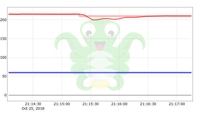
I have the same problem. For me it started after the R3 part upgrades on my MK3. When the hotend temperature drops on the second layer and the part cooling fan kicks in there is a 10°C undershoot and it takes almost a minute to recover to the proper temperature. I upgraded from 3.3.1 to 3.4.1 and re-ran the PID tuning, but it still happens.
I understand adding an E3D Silicone Socks may prevent this, but it seems like the printer should be able to properly adjust without the sock.
 OmenWild
on 26 Oct 2018
OmenWild
on 26 Oct 2018
Related issues
 duartemv
·
5Comments
duartemv
·
5Comments
 sgoll
·
3Comments
stahlfabrik
·
5Comments
sgoll
·
3Comments
stahlfabrik
·
5Comments
 RacingHell
·
4Comments
RacingHell
·
4Comments
 erikcramerjr
·
4Comments
erikcramerjr
·
4Comments
Most helpful comment
I totally disagree. It's just another (predictable) system variable, just like kinematic variables such as extruder head velocities and current z height (as you said) or even the already printed plastic underneath the extruder for a much more advanced hypothetical printer's firmware who has access to STLs and can process them. Feeding these variables into the controller based on a physical system model of the printer makes it a slightly customized kind of controller derived from stock PID, nothing more and certainly nothing exotic.
You could in theory devise much more complicated controllers for the extruder temperature, e.g ones involving neural networks (someone up for this task? :D). These kinds of more advanced controllers are prevalent in the scientific literature. Would these be overkill for consumer 3D printers who usually have to track one temperature at a time? Almost certainly.
Silicon sock is a good idea in the long run, if it's designed correctly so that it's robust against vibrations and doesn't fall off randomly. However, such a design is not stock yet for mk3 and those that are available seem to have issues. I haven't tested these on any printer I used so far so I cannot say for sure.
I don't think it's a good idea. Scenarios like PLA printing may need immediate cooling depending on the part's geometry, meaning that this kind of ramp up may not be enough.
Just as a side note, I performed the PID calibration from the menu (with/without fan at full speed). The results are slightly worse than factory in both cases, overshooting significantly up to 6 degrees when getting up to temperature (was 2-3 with factory settings) and dropping by -11 degrees when the fan turns on. Having recently assembled my mk3 kit, I haven't had the time yet to calibrate through
M303and I'll do that next. In the end, I'll most probably not be satisfied with that either and hand tune my PID coeffs like I always do.