Prusa-firmware: Inconsistent Extrusion
 TheBrigandier
All 1241 comments
Yes! This is driving me crazy as well. Thanks for isolating this more @ff8jake ! I've got a pile of calibration cubes printed with different slicer settings and was never able to make the issue go away.

 HeySideburns
on 5 Apr 2018
HeySideburns
on 5 Apr 2018


S3d with a brim, slic3r without. john.n13
Here's an s3d version with fan turned off half way up wall - at the mark:

 TheRedcoat
on 5 Apr 2018
TheRedcoat
on 5 Apr 2018
More examples:


TheBrigandier
on 5 Apr 2018
Just want to add that I compiled 3.2.0 alpha as of today's commits with no change on this issue.
TheBrigandier
on 6 Apr 2018
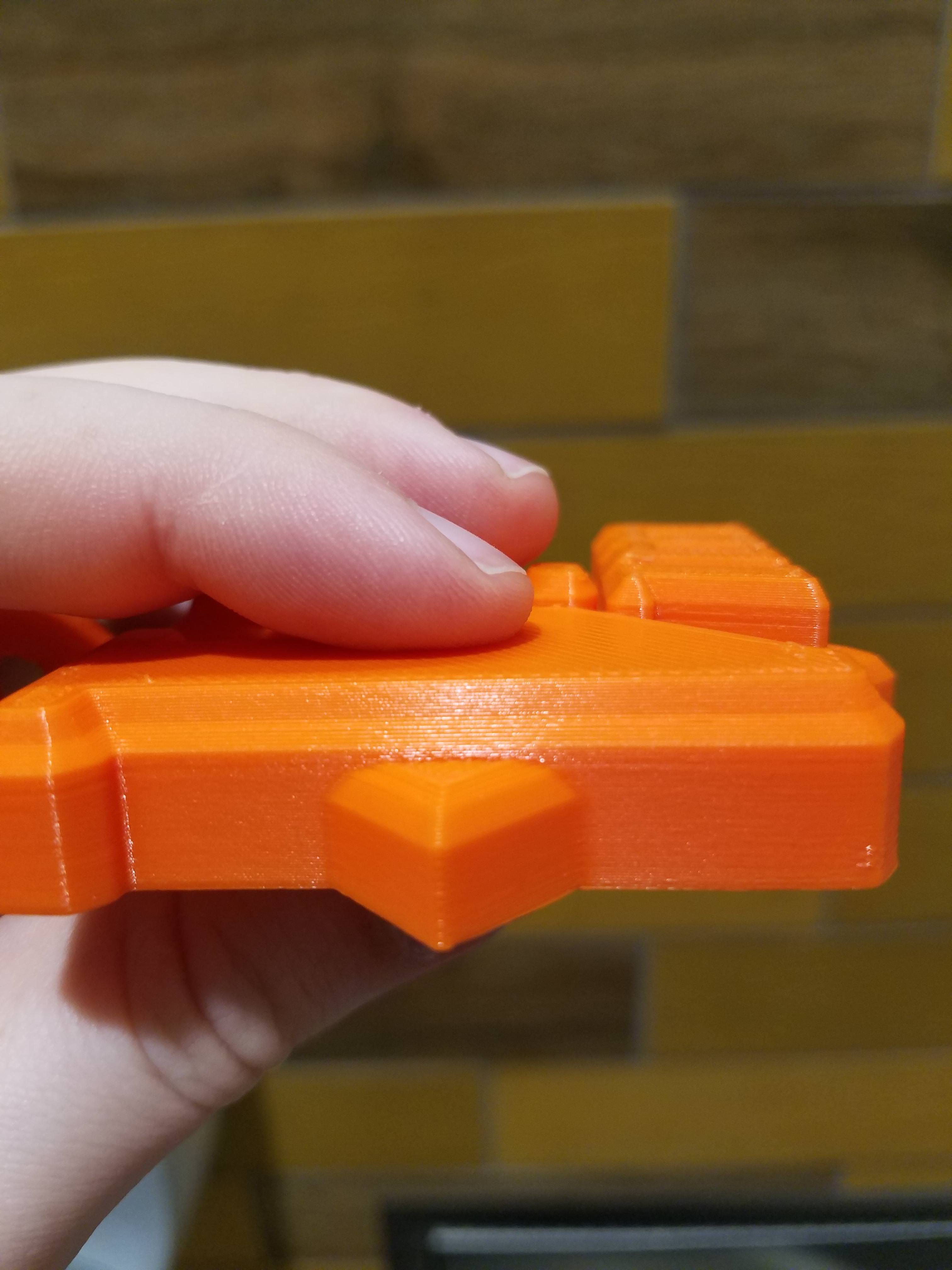
Just to highlight the problem only shows up when indirect light is hitting the print, here's a single wall test piece I just did with and without my phone flash:

TheBrigandier
on 6 Apr 2018
Not the single wall box, which I will try later, but one example of somehow irregular extrusion on my MK3 using 3.1.3 firmware version.

However, I reckon output quality was better when the filament was freshly opened.
 misan
on 6 Apr 2018
misan
on 6 Apr 2018
Did you try to calibrate your extruders? Which slicer did you use? Did you tried another slicer like Cura, IceSL-slicer, ideaMaker (all free), PrusaControl or different versions of Slic3r PE?
Did it change with the firmware update?
 3d-gussner
on 6 Apr 2018
3d-gussner
on 6 Apr 2018
Did you try to calibrate your extruders? Which slicer did you use? Did you tried another slicer like Cura, IceSL-slicer, ideaMaker (all free), PrusaControl or different versions of Slic3r PE?
Did it change with the firmware update?
Extruder calibration appears to be spot on (single wall thickness matches Slic3r setting of 0.45mm precisely). I have been able to reproduce this artifact on both Slic3r and S3D. I am getting this issue on both 3.1.3 and 3.2.0 Alpha.
So far the only thing I have found that lessens the effect is cutting the flow rate waaaay back (70%) which gives horrible inaccuracy, or dropping temp to around 195 (from the default 210) and having to print very slowly, or turning the external perimeter speed way up and dealing with ringing. The lower temp works fine for single wall cubes, but it causes clogs on the higher speed movements like infill.
Could it be that the temp is too high for the slow external perimeter speed required to prevent ringing? I understand it needs to be up there to get the filament flowing at the fast rate, but it also seems to be extremely oozy out the nozzle at 210 when stationary. If lowering the temp ends up being the answer, then all speeds across the board would need to be dropped...
TheBrigandier
on 6 Apr 2018
I’ve also had the same issues as listed about, just to confirm also... cura, slic3r and S3D all have the same results. So far I haven’t seen a print off a mk3 without this happening.
There is tons of pictures on Facebook to back this all up, it doesn’t matter what I try the issues remains. Just to Also make clear this isn’t material specific either, PETG is also as bad.
Thanks Jon
 jonbet83
on 6 Apr 2018
jonbet83
on 6 Apr 2018
I have also noticed this. I was convinced I didn't have my extrusion multiplier set right. I did calibrate my extruder and my single wall cubes were coming out .45mm ish. I assumed I hadn't dialed my slicer settings in but it's possible I am having a similar issue to OP.
 mvasilakis
on 6 Apr 2018
mvasilakis
on 6 Apr 2018


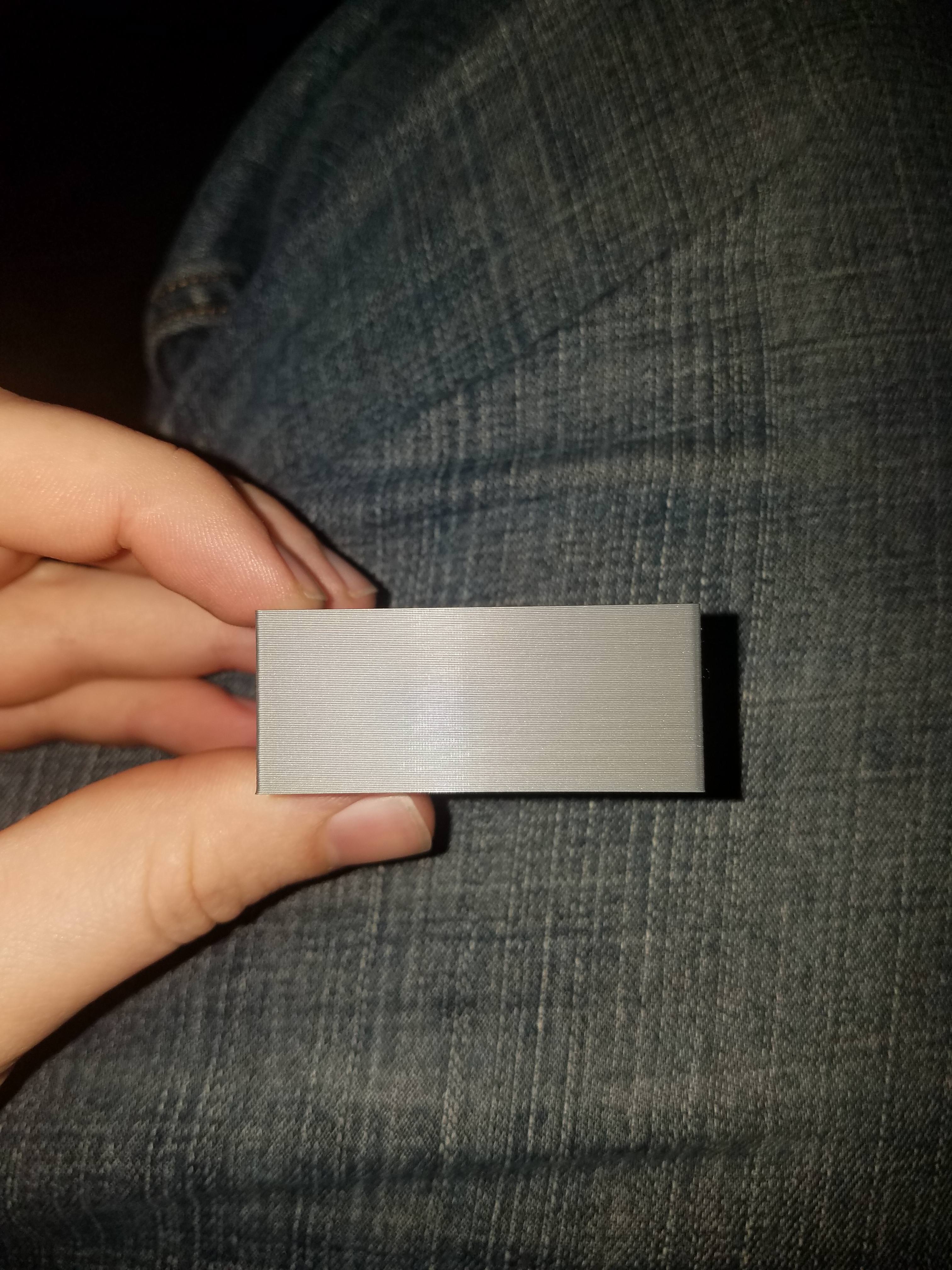
Same here: printed in vase mode on 2 mk3's. the red one on a pre-assembled mk3, the silver one on a self assembled kit. FW 3.1.3
 vanvlierden
on 6 Apr 2018
vanvlierden
on 6 Apr 2018
I own a MK2s Prusa printer and I can add that this is the case for my printer also. Only with ABS I have good results. The PETG produces the worst.
 Panayiotis-git
on 6 Apr 2018
Panayiotis-git
on 6 Apr 2018
I sped it up 1/3 to the top.

misan
on 6 Apr 2018
Could this really be adressed to the extruder stepper movement? Had kinda similar results on earlier firmware with 0.25 nozzle underextruding, but flowrate already was fixed. Otherwise the ominously „clicking back slapping extruder“ might cause this. 3rd mention I would have might be bad manufactured (concentricity) or dirty bondtech gears.
 RacingHell
on 6 Apr 2018
RacingHell
on 6 Apr 2018
More pics from the forums. @josefprusa @PavelSindler @XPila


TheBrigandier
on 7 Apr 2018
Couldn't that be caused by inconsistent filament diameter?
Chris
On 04/05/2018 01:27 PM, HeySideburns wrote:
>
Yes! This is driving me crazy as well. Thanks for isolating this more
@ff8jake https://github.com/ff8jake ! I've got a pile of calibration
cubes printed with different slicer settings and was never able to
make the issue go away.—
You are receiving this because you are subscribed to this thread.
Reply to this email directly, view it on GitHub
https://github.com/prusa3d/Prusa-Firmware/issues/602#issuecomment-379065815,
or mute the thread
https://github.com/notifications/unsubscribe-auth/ABPAj9-Pmi1fa9RQ2PHo4EZ1-SDSieH8ks5tln4WgaJpZM4TI5uR.
 cjshaker
on 8 Apr 2018
cjshaker
on 8 Apr 2018
Any progress PRUSA?? I get the feeling you seem to be ignoring us on this topic, It would be nice if someone could at least come and give us some advise or say what your thinking???
jonbet83
on 8 Apr 2018
Please note this part, being a single perimeter, was being slowed down to keep a minimum time per layer. When I sped it up 2/3 to the top extrusion became more uniform.

misan
on 8 Apr 2018
I am printing a 200x200mm single wall part currently, no change.
TheBrigandier
on 8 Apr 2018
I'm having the same issue with my MK2. Prints were coming out great and then all of a sudden the issue started. I can't remember if it coincided with a firmware update or not unfortunately.
Edit: Just looked at my older prints and they actually are the same. The lighting that you look at the print under makes a MASSIVE difference.
The extruder is calibrated. I even tried lowering the extrusion multiplier to the point where there were gaps on the top layer, but it made no change to the inconsistent side walls. Tests were done with multiple high quality filaments - no change in the results.


As you can see, the visibility of the inconsistency is definitely dependent on the lighting. These pictures were of the cali cat but the same thing happens with all other prints, including a single walled cube. I'll do some testing with earlier firmware versions and see if the issue still presents itself
 Matts-Hub
on 9 Apr 2018
Matts-Hub
on 9 Apr 2018
@PavelSindler, how about a statement or analysis or progress on this issue?
 ghost
on 10 Apr 2018
ghost
on 10 Apr 2018
@cjshaker - I don't think filament inconsistency is the issue here, since it's happening for a lot of users using many different filament rolls. I've had this happen since day 1 with lots of filaments, some of them very high quality.
I'm also getting these on my MK3. It doesn't look like an axis issue, but an extrusion issue. Look at the octopus' head:

If this was an axis issue, the circles would be misaligned. This is not the case here - you can clearly see the extrusion lines being very inconsistent.
This has persisted through a nozzle swap as well.
 MoshiBin
on 11 Apr 2018
MoshiBin
on 11 Apr 2018
These were not printed by myself but kindly by Eric Clinedinst who has pretty much every variant of mk2/3.
The following prints were from (top to bottom)
Mk3
Mk2.5
Mk2s
Mk2s with MMU

and the printers:

The prints were sliced with the exact same slicer settings, checked with slic3r PE vs S3D, Linear Advance enabled and disabled, in every case the result remains the same.
The fact that the Mk2.5 has the same print surface quality problem (caused by what clearly seems to be inconsistent extrusion for whatever reason) as the Mk3 means we can rule out the Mk3's einsy board as a possible culprit.
The only remaining possible culprits I can see are as follows:
1) Use of bondtech extruder gears. I don't think this is likely though and given that his print with the Mk2s MMU (that uses the exact same bondtech extruder gears) came out exactly the same as his Mk2s print seems to support this. Having said that, the fact the MMU is a bowden setup could be masking its affect if present though from the slack in the bowden acting like a dampener/smoother on the filament feed rate. I still think this is unlikely but I cannot rule it out (yet).
2) Use of Mk52 heatbed. I can't see how or why but like with the bondtech, I can't rule it out the possibility completely (yet).
3) Firmware. This I believe is the most likely culprit. Both Mk2.5 and Mk3 use new (but seperate) firmwares that diverged from the Mk2s's last (November 2017). I think there is a reasonable chance that the culprit lies with this.
Eric has kindly offered to help try to troubleshoot this problem. He's currently in the process of performing tests that will hopefully be able to narrow down the culprit. Will keep you all informed of the progress and findings.
Additional comments:
Eric distinctly remembers his now Mk2.5 printing as well as his remaining Mk2s before he converted it to an Mk2.5 from an Mk2s. And the fact the prints come out with identically looking and distinct problems as the Mk3 vs. the mk2s just drives the point home that it's not random or caused by user error/incompetence for any that think it might be. The problem is also way too consistent for so many to be that too.
 MTJC
on 11 Apr 2018
MTJC
on 11 Apr 2018
@MTJC - Awesome, this brings me a little more hope Prusa will acknowledge this issue and get started on a fix.
TheBrigandier
on 11 Apr 2018
The MK2s prints directly to the PEI Sheet, if three is the slightest off vibration up or down laying down the filament ? on the MK3 on the PEI Sheet with the steel sheet.
if you have 0.2mm layer and 0.1mm vibration and the steel sheet acting as a speaker and amplifier.
Can that do this ? to me on the images I have see it looks like the filament moving around on the top off the wall is hard to see on many images true.
Only way is to test it to be sure.
 alfskaar
on 11 Apr 2018
alfskaar
on 11 Apr 2018
@ff8jake - Agreed. If we can confirm that it is indeed firmware and easily prove it, then i think it can galvanise enough mk2.5/3 users into demanding Prusa Research to a) recognise it's real and b) do something about it (since it should be resolvable).
@alfskaar - nice idea but I suspect you don't have an mk2.5/3 because if you did, you wouldn't have any doubts that couldn't be the cause. The steel sheets stick extremely well to the Mk52 heat bed.
MTJC
on 11 Apr 2018
@alfskaar your idea about the speaker might be genius.
So I guess printing without heat on the bed should be all that is need to prove or „counter prove“ that theory.
Cause yes. The heatbed clicks audibly so it DOES swing.
EDIT: Is it possible to set bed temperature via the tune menu during print? If so, could someone print half a cube with heat bed on and upper half with heat bed off?
 stahlfabrik
on 11 Apr 2018
stahlfabrik
on 11 Apr 2018
My MK3 is boxed for awhile (needed to make room), but it seems to me that if this were due to the steel sheet, we'd see differing results depending on bed position. Can anyone try a cube or five in the center vs the corners of the bed just to rule this idea out?
TheBrigandier
on 12 Apr 2018
Just in case, I printed this with the heatbed off:

Now I am repeating the print with the heatbed on, I will report back later. But so far the above print looks better than the first test I uploaded to this thread.
misan
on 12 Apr 2018
@MTJC you are correct I don´t have one yet. Consider getting one.
@stahlfabrik interesting findings now I relay start to wonder what happens when it heat up and cool down, also make you wonder why nobody have done this before, if you look at the Build tack
it have a magnet that is covering the bed and I think the steal sheet is thinner.
@misan very interesting.
I resonantly cut a small steal sheets, thickens 0.7mm 122x127mm and I notice the resonance in the sheet and that it is not flat.
Eave to my very small bed it was only one way I cold use it to make it as flat as I can. In my first design I did not have enough magnets I had to add 4 more magnets around the center.
I learn that I had to use the magnets to suck down the air pocket at the center off the bed it simply did not work the other way around. My bed is not heated.
Also it will be impossible to use the steal sheets on both sides alt least for the one I have.
The MK3 Is similar to a Race Car if I may use that comparison.
When you change sow many things as the same time is hard to predict the outcome.
There is really only on way to find the problem and that is to start back tracking and see where did it go wrong.
At the resent pictures off the Benchy at the Prusa forum it real looks like something is moving around again this may not ONLY be the steal sheet it can be multiple things.
The user say that if he use 0.15mm layers problem is bigger and if he use 0.20mm layers problem is smaller.
Also moving the bed around with the steal sheet it is more heavy, but the stepper motors is the same and the gearing is the same as fare as I know.
I will be very interesting to see what a long digital dial indicator will show on the Z axis, when it moves up, you need two on one both Z axis.
This will be and expensive test if you need to invest in this tools, I do have two short ones as I do use it on my Trinus and my Sherline CNC mill.
But I really think you need a long one at this may only occur at some places maybe it is missing steps or Z1 and Z2 getting out off sync.
You may be able to use two or one digital caliper if yo make a jig that can hold it it will not be perfect but may give you and indication.
It can also be imperfections on the lead screw, or backlash making the Z1 and Z2 move around/UP/DOWN.
Flipping the steal sheet around may be interesting to test to.
I am not going to suggest adding PEI directly to the bed as I under stand it is a pain to remove.
What about the magnets are there any parts under the bed that magnets can try to stick to ? or slow something down ?
Only trying to help as it will be in my interest to that this is fixed :-)
alfskaar
on 12 Apr 2018
The one with the heatbed on:

But just in case you want a side to side comparison (left one is with the heated bed off):

I would say, the one on the left looks cleaner.
misan
on 12 Apr 2018
The story about the magnetic heat bed is that it clicks synchronized with the power/ LED.
So it must vibrate as well.
So the question is if that vibration affects print quality.
If so, a better way to drive the heatbed would be needed
stahlfabrik
on 12 Apr 2018
@stahlfabrik
If so, a better way to drive the heat-bed would be needed
The best way to minimize this problem is while designing the tracks on the bed, to minimize the impedance of the circuit.
@misan
Even if the moire effects are slight visible on both your prints, it seems to me that the left one (printed with the heated bed off) has more extrusion problems than the right one.
Panayiotis-git
on 12 Apr 2018
How about trying a test that eliminates the steel sheet altogether? Use blue tape on the heated bed without the steel sheet and compare the results.
 rcfsguy
on 12 Apr 2018
rcfsguy
on 12 Apr 2018
If you print say, a 60-80mm cylinder and watch the Z motors, they slightly turn as the X and Y makes the "circle". I guess this is its adjustment from mesh bed leveling? If so, has anyone tried to remove that from the equation? Could it be this calculation is off?
 Skiidlive
on 12 Apr 2018
Skiidlive
on 12 Apr 2018
That does not work because the PINDA will grind into the heatbed during mesh bed leveling. IMHO
stahlfabrik
on 12 Apr 2018
@stahlfabrik Dohhh, I didn't think that one through. Sorry, I just woke up. :)
rcfsguy
on 12 Apr 2018
@Skiidlive Yes, that is the mesh leveling turning your Z steppers, and yes, I have tested this with mesh leveling disabled. I had my bed leveled to within 0.025mm (by using this: https://github.com/ff8jake/OctoPrint-PrusaMeshMap ) so I was able to print solely with the initial auto home. No difference was observed. Additionally, if this were a mesh level issue, we'd likely see more of a pattern to this instead of random fat/skinny lines.
TheBrigandier
on 12 Apr 2018
@ff8jake I just realised it's you brigadier. Hehe. Btw, when you managed to print without mesh bed leveling, did you notice whether any of the moire's pattern changed or went away by doing so by any chance?
MTJC
on 12 Apr 2018
@mtjc Yep, it's me. :)
Not that I remember. Moire pattern is directly affected by the stepper linearity correction though. It's irritating, as it's compounding this issue.
If you're running 3.2.0 Alpha and copy the variant file for mk3 over (usually it's already in place, but I have been noticing sometimes the variant file has #defines flagged differently than the one sitting in Configuration_prusa.h), you can toy with linearity correction in settings. 1.100 is recommended last I checked, but that doesn't work in my experience. You can definitely tell a difference at say 1.050 if you hold the pieces to the light and compare looking down the moire lines. I haven't been able to arrive at a setting that makes it go away completely yet. I have gotten close enough to be fairly certain they are separate issues though. I can affect a change in moire easily, just can't get the inconsistent extrusion to change that I can see.
TheBrigandier
on 12 Apr 2018
@ff8jake indeed. I've been playing with the E-Correct constant on 3.2.0a as well and confirm your findings that while that setting does effect the 'moire' pattern on the surface finish of prints, it doesn't seem to affect the wavy inconsistent extrusion issue.
 c-stewart
on 13 Apr 2018
c-stewart
on 13 Apr 2018
I did find this interesting reading.
http://www.prusamk2.com/get-great-first-layer-original-prusa-i3-mk2-bed-level-correction/
If the mesh bed leveling is giving problems. Or other new functions use older firmware or try to turn it off to see if it possible can be a firmware issue in combinations with hardware.
It will be interesting to turn it all off and do manual bed leveling.
But that involved some work to pull that off.
I have some parts that is printed on the MK2 I will have a close look at them, but I don´t remember that there was any indications on what we see hear. And the parts looks greet.
The person at 3d hubs that printed them do have lots off experience.
Soon I need to decide what to get. I really like to get a bigger machine.
I most likely will need to do several modifications to print at 100/280 I need high temp to print strongest possibly parts.
I am playing with the idea/dreaming to do a product case and look into getting a Markforged I do not know if it can produce the parts as strong as I need them.
alfskaar
on 13 Apr 2018
@alfskaar interesting read, fairly certain this isn't a mesh leveling issue though. Using this https://github.com/ff8jake/OctoPrint-PrusaMeshMap and installing wave springs under the 9 bed mounts I was able to not only level my bed but get variance across it down to 0.025mm~, level enough to completely disable the G80 bed correction and print strictly with autohome like a printer without mesh level correction. It made no difference unfortunately.
TheBrigandier
on 13 Apr 2018
Here's an idea, can someone attempt to extrude several lengths of filament, say 10mm each, and measure them precisely with calipers (above the extruder, obviously)? It looks to me that if this is inconsistent extrusion at the stepper level, we should have a measurable variance in lengths that actually get extruded.
Edit: If anyone decides to do this, make sure to take the measurements down in order and do several. Would be interesting to see if this is cyclic in nature.
TheBrigandier
on 13 Apr 2018
ff8jake So your thinking is even with the extruder calibrated correctly, several say 10 separate extrusions of 10 mm will not have extruded 100mm?
Skiidlive
on 13 Apr 2018
@Skiidlive that, or if it's extruding more or less in a pattern, the 10mm lengths would vary. Say one 9.5, 10, 10.5, 10.3, etc. The issue is if it's cyclic, at the end of 100mm it may seem like everything is fine, but in reality you have extruded 100mm total but at different rate of speed the entire way through that 100mm.
Does that make sense? I guess what I am saying is many people have tested extrusion calibration with long lengths of say 100mm, but we need some tests done with smaller lengths to determine if this may be caused by bondtech gear wobble, oval shape, or something similar.
EDIT: We should probably test with a length that is half the circumference of the bondtech gears. With this, we should see a back/forth length if they are off.
TheBrigandier
on 13 Apr 2018
@ff8jake Yes, I will try most anything at this point.
Skiidlive
on 13 Apr 2018
@ff8jake The difference was immeasurable with the calibration method my calipers and my glasses on. My fine marks stopped at the tip of the inlet every time. Best I can do without a counter of some sort attached to measure the filament.
Skiidlive
on 13 Apr 2018
@ff8jake many thanks for the update.
I have the funny story that when I wanted to get the MK2 but the wait killed me and I got the
Trinus one off the things I really wanted was the "mesh bed leveling" no I really like to have a
MK2 or MK3 but manual bed leveling good to know it is possible.
@ff8jake
@Skiidlive
Maybe this extruding test will not work as you have no resistance. ?
I suspect that you need to get the extrude motor hot before you start to see problems.
Or did you extrude going true the hot end ?
If this is a blind end ?
Do anyone have a oscilloscope ?
what if this i ripple ? spikes volt drop amp drop ?
if I am not mistake all problems is with 120 volt ? or are I wrong ?
alfskaar
on 13 Apr 2018
I had the problem on my mk2s and now on my mk3. I had this also on my old tevo printer with bowden But I forgot How I fixed it. I changed too Many things hard and software Its hard to pin point
 dielessen
on 13 Apr 2018
dielessen
on 13 Apr 2018
Btw Im on 220v. I Dont think Its a voltage thing
dielessen
on 13 Apr 2018
FYI, a new release candidate just went out and "extruder linearity correction" is listed as a feature. We might be able to tweak these settings more easily now that they're on an official RC (easier to get testers?) https://github.com/prusa3d/Prusa-Firmware/releases/tag/v3.2.0-RC1
MoshiBin
on 13 Apr 2018
@moshibin many of us have already been playing with that feature for awhile with our own compiled firmwares. It affects the consistent moire/banding artifact, but not this inconsistent extrusion. I have used the linearity correction to very nearly get rid of the moire (it works), but it has no noticeable effect on this issue. I can confirm the commits since these tests haven't touched anything in that department since our tests as well.
Has anyone tried a cube with absolutely no filament "tug" from above from the spool? Say a test cube while holding the filament loosely above the extruder? I am curious if the extruder is tilting up slightly before the spool holder gives.
TheBrigandier
on 13 Apr 2018
https://shop.prusa3d.com/forum/user-mods-octoprint-enclosures-nozzles--f65/mk3-filament-spool-bowden-tube-feeder-t15550.html#p77647 Bigdogbro1 has a Bowden tube rigged up in a way that it wouldn't have upward pull. Asked him if he can print us a cube.
TheBrigandier
on 13 Apr 2018
@ff8jake I've tried exactly that. I cut some loose filament and just had it resting on the spool holder. Unfortunately no difference
Matts-Hub
on 14 Apr 2018
Have extruder temperature fluctuations been eliminated as a possible source? I saw a video on YouTube by CNC Kitchen talking about PID tuning showing that he was getting a +/- 5 degrees C oscillation around the set temperature before running a PID calibration. https://youtu.be/4NlPzp05VwY?t=1m33s
 TheDuggem
on 14 Apr 2018
TheDuggem
on 14 Apr 2018
@TheDuggem Yes, I am seeing this with no temp variance. Attempted a PID tune just to make sure of this. Also attempted printing extra hot to affect this. No change.
TheBrigandier
on 14 Apr 2018
I tried also about all options possible.
Leaving only some options :
Hardware design .
Motherboard / stepper drivers
Stepper motor
Firmware specific prusa settings.
dielessen
on 14 Apr 2018
I still wait for my MK3 but is there any chance that the MK3 speed setting get the printer to resonate at specific speeds and gcode: Checkout CNC Kitchen Prusa i3 MK2 - Practical Vibration Analysis video
https://www.youtube.com/watch?v=Ws1JfHl3Y0o
I know the chance with a calibration cube is small but you never know.
3d-gussner
on 14 Apr 2018
@3d-gussner We tried this as well in the Prusa forum thread I believe. I know I have tried slowing it down to 50%, and I have tried keeping it as fast as 400% with high heat. Very high speeds made a slight improvement (I suspect more consistent pressure on the nozzle?), but at the speeds to get that effect I was up to ungodly amounts of ringing.
Regarding the size of the print, I also did a 180x180 single wall cube awhile back (wanted something to get an Xbox a little higher so the IR sensor was visible in our cabinet lol). Same effect all the way around. Considering the varied amounts of prints showing this (including those with curved varied perimeters), I don't think resonance is to blame; however, that video before did lead me to finding that the MK3 has horrible vibration when moving in Y, particularly so in movement towards the front. If you do a calibration cube at high enough speed to see ringing, you'll notice your ringing is worse on the side the print bed is moving forward on. :)
TheBrigandier
on 14 Apr 2018
@ff8jake
" If you do a calibration cube at high enough speed to see ringing, you'll notice your ringing is worse on the side the print bed is moving forward on. :)"
Very interesting that have to be magnets or binding.
Magnets slowing down the print taking up the slop/damping (mass damping) off the belt.
Raise the bed.
Read on pleas as I see your post after I write all under this line.
I am starting to think that this is a combination off things.
Can someone disconnect the belt from the Y axis and try to squish / move the bed with one finger to rule out any binding or any magnets trying to grip on to something ?
You need to do the test with both the steel sheet on and off.
The weight off the bed make it harder to feel sow as a last step you should remove the heated bed to and only try to move the "Y-carriage"
If there is any binding I will remove the single U-bolt and replace it with the old method zip tiers, if it still bind I will then remove the two on the other side to and replace with zip tiers.
Not having 3 U-bolt under there give you less metal but, if it bind may be more important as I m not sure how close the magnet are.
Next I will consider to use longer spacers and longer screws most off the kit according to the manual have 12mm I will double the length.
depending on length on screws you can print some spaces but they may not last long but if the heated bed is off it will be a start.
Then you need to calibrate it, losing some Z is a small price to pay if this will help.
It is also possible that the magnet is not gripping on to something but slowing things down (inconsistency), that is why I will like to raise the bed.
And maybe some grease in the bearings is needed to.
alfskaar
on 14 Apr 2018
@josefprusa @XPila @PavelSindler Guys, this ticket has been open over a week and has over 60 comments, can we at least get a "Yeah we see it" from you guys?
Also, devilhunter on the forums has built two machines from scratch with COMPLETELY different hardware except for the Einsy, magnetic bed, and fans. https://shop.prusa3d.com/forum/general-discussion-announcements-and-releases-f61/i-made-custom-scratch-built-mk3-clones-and-yes-you-t15658.html#p77755 - His machines have this exact same issue, so I think it's likely safe to say this is a software issue or an Einsy issue.
TheBrigandier
on 14 Apr 2018
@ericclinedinst

Great. "Not much we can say about it, when we don't know what's causing it. But we can continue to ship them out to customers and collect their money, so we have that going for us!"
We've yet to find an MK3 that doesn't experience this issue. Stop jerking our chain already @josefprusa, you guys are seeing this on yours just as much as we are on ours. You should be ashamed of your business practices.
TheBrigandier
on 15 Apr 2018
@josefprusa @XPila @PavelSindler Guys, this ticket has been open over a week and has over 60 comments, can we at least get a "Yeah we see it" from you guys?
Most likely because as soon as they do that, they have to spend hours upon hours (at 1am at night it seems) to reply to facebook posts guessing what might be the cause of it, instead of working on fixing it.
And since some people seems to be very very impatient as soon as they don't get an instant reply, I understand their silence. (I also understand the frustration, since I myself has been quiet impatient with PR in the past, so I know the feeling)
 GurliGebis
on 15 Apr 2018
GurliGebis
on 15 Apr 2018
Lack of communication only seems to sow more distrust. A concise "We're on it" or "It's on our list" does not warrant hours upon hours of replies; just acknowledge this issue so we'll know it will be fixed eventually.
Ultimately we did get this acknowledgement, it's just unfortunate that it had to devolve into that facebook argument.
MoshiBin
on 15 Apr 2018
History has just shown, that once things has been acknowledged, people keep asking for updates.
Just look at the Facebook post above, Eric is already asking what they expect might be the issue, even though it is pretty clear they don't know yet.
GurliGebis
on 15 Apr 2018
@ericclinedinst can we try to keep this thread for technical discussion rather than harassing staff? The SNR is rapidly deteriorating at the moment.
 cjo20
on 15 Apr 2018
cjo20
on 15 Apr 2018
@ericclinedinst the only thing you are accomplishing is to annoy PR.
Can you explain how asking what Joseph think is the cause is helping?
If they knew, and they told, then instantly everyone would start demanding an instant fix for it.
I hope they find a solution soon - trying to get different Youtubers to cover it won't make it any faster, just waist more time.
GurliGebis
on 15 Apr 2018
From what I have done and read I reckon the problem (which I consider a mild one) could be connected to:
- Bondtech gears: either some of them are defective, or the mount creates a defective working mode, or they pick up debris in a way that does not self-clean
- TCM stepper driver: either the drive logic creates a not so linear motion with micro-stepping, torque ripple could easily explain what we are seeing here.
- E3D hotend: some turbulence in the melt zone could cause uneven flow
That said, I think that both E3D and Bondtech are well-known products, with a proven record, so that makes it quite unlikely to be the source of the problem.
Increasing micro-stepping may induce its own problems as explained here https://www.micromo.com/media/wysiwyg/Technical-library/Stepper/6_Microstepping%20WP.pdf that might be coupled with certain extruder steppers ... ?? so not all users experience the problem ... ??
Let's see if some test firmware is made available to rule out this hypothesis.
misan
on 15 Apr 2018
@misan As it was pointed out earlier, we're seeing this on an MK3 built from the ground up (with completely different hardware, save for the Einsy, magnetic heat bed, and fans). That knocks out 1 and 3 on your list likely. TMC stepper driver is possible, maybe, and we're already seeing linearity correction added to firmware to help with the predictable moire pattern (not related to this, that we can tell). Could still be the Einsy or TMC drivers (or firmware).
Also in regards to torque or skipping steps, I have dropped this down from 32 microsteps to 8. No change, so I took it a step further and disabled the TMC microstep interpolation (looks at your steps and automagically interpolates up to 256 steps), again no change other than the printer got a hell of a lot louder.
TheBrigandier
on 15 Apr 2018
https://youtu.be/bZGJ9M62L0M
Have a look at 06:20 don't know if it can be related.
alfskaar
on 15 Apr 2018
@misan @ff8jake Additionally regarding the E3D V6 hotend - The MK3 has a special heatbreak marked by a red section in the middle. In the Prusa store it is marked as the MK3/MMU heatbreak. I have replaced my entire hotend with a new one from E3D, with a regular V6 heatbreak (no red section). I can confirm that it did not affect the issue we're seeing in any way - older prints with the MK3 heatbreak have these lines, newer prints with the default heatbreak also have these lines.
MoshiBin
on 15 Apr 2018
Today I replaced the stepper motor and hot end for new, it had no effect on the problem.
I also replaced the x axis bearings for SKF, while that hasnt had an effect on the problem it’s has made that axis total silent.
jonbet83
on 15 Apr 2018
Here is mine. Note on what SHOULD be a flat surface there are clear ebbs and flows of the filament.
Also notice there is a clear pattern where it extrudes more, then almost comes to a stop in other areas.
Note my prints from ~2 days ago didn't have this problem. So it's clear there is something intermittent about this, probably firmware.

 rackley096794
on 15 Apr 2018
rackley096794
on 15 Apr 2018
@ff8jake
Progress, perhaps?
chris.s39 and me perhaps found something.
See here:
https://shop.prusa3d.com/forum/general-discussion-announcements-and-releases-f61/i-made-custom-scratch-built-mk3-clones-and-yes-you-t15658-s10.html#p77928
and the conversation downwards.
Quoting chris.s39:
In stock Marlin when you use software auto bed level correction you can choose a height to fade the correction out by (so the z doesn't keep moving throughout the entire print: M420 Z0.2 or something like that) I have no idea whether the mesh bed corrections are faded out after a while in Prusa's firmware or not. If they aren't, then yes the z would keep moving along the mesh for the entire print. If they are faded out, there is a specific point in the print where the z will not move along the corrections anymore.
http://marlinfw.org/docs/gcode/M420.html
And quoting myself:
Then we have found our culprit/one of our culprits for the extrusion issues.
I'm currently 10cm high into a print, and the couplers still wobble from side to side.
The MK2 feverishly locks down the Z motors with a high holding current, so that the motors get hotter when holding then they would moving.
And guess what, the old MK2 firmwares does not have this problem.
The MK2.5 firmware, same old board, introduces this problem for the older machines.
So a software dev most likely half baked this feature into the firmware versions above 3.1.x somewhere.
I would start here, if nobody has any leads where to look.
 devilhunter84
on 15 Apr 2018
devilhunter84
on 15 Apr 2018
Hello, I'm chris.s39 on the prusa forums.
It would make sense to me that if for some reason the mesh bed level corrections were not being faded out, and the z motors were moving up and down slightly during normal layer printing, that could possibly create artifacts like we're seeing.
It would be interesting to see if someone could get stock Marlin configured for a mk3...
c-stewart
on 15 Apr 2018
However, wasn't someone able to run a print without bed leveling, and it didn't help? I think that would negate this theory
c-stewart
on 15 Apr 2018

good night, after testing and dismantling many times I decided to put the v6 direct to bowden and the impressions to a perimeter were the same, the problem of extrusion is clear, the body of the bondtech is not well designed. I pass photos to you.


 austaquio32
on 16 Apr 2018
austaquio32
on 16 Apr 2018
@devilhunter84 @c-stewart Alright, you made me dig my MK3 out of the box and plug it back in. :)
Took 3.2.0 RC1, commented out MESH_BED_LEVELING and went through all the firmware errors that popped up because of it until I finally got a working firmware. I can confirm my original 50mm single wall cube no longer performs the G80 it was doing before. Unfortunately, no change. :(
TheBrigandier
on 16 Apr 2018
Darn. Thanks for all of your continued effort @ff8jake
c-stewart
on 16 Apr 2018
@ff8jake
Please try it with the tape to the leadscrew method, to see if its still wobbling from side to side if you already have the MK3 out.
devilhunter84
on 16 Apr 2018
@devilhunter84 What do you mean tape to leadscrew, as in some indicator of movement of the screw itself? At the bottom of the lead screw there are dust covers, and I watched each one for about four or five layers. Zero turn during print on both steppers. Is that what you are meaning?
TheBrigandier
on 16 Apr 2018
Yes, that. Tape works better bc its longer to See movement. Also print something larger like a 80x80mm rectangle (no top/bottom layers, perhaps some grid infill
devilhunter84
on 16 Apr 2018
@devilhunter84 found some tape, couple inches away from the lead screw, no movement except when layer change happens. Got another test going now with super old b137 firmware, to see if this was a firmware regression. Will report back in a few.
Edit: No change.
TheBrigandier
on 16 Apr 2018
JFYI. I tried to decouple lead screw from X gantry using this method:

And it changes nothing, extrusion inconsistency is not related to lead screw wobbling.
 sneaky-tricky
on 16 Apr 2018
sneaky-tricky
on 16 Apr 2018
@devilhunter84 Well, I give up again. Things I tried tonight:
- Disabled MESH_BED_LEVELING, no change. Confirmed no movement in Z steppers during prints except during layer changes,
- Tried Slic3r vs S3D again, no difference,
- Tried bumping E motor current up (to same setting as Z), no difference,
- Tried old (b137) firmware vs new, no difference,
- Tried locking down bondtech gears in case the springs were allowing it to vary travel distance, no difference,
- Tried setting very high jerk settings on the off chance maybe some wonky acceleration was affecting things, no difference (other than some more ringing, yay),
- Tried looking at other printers online to provoke jealousy and maybe get better performance through damaged confidence, no difference (printer appears to be proud of how shitty it prints).
The only thing I can say about tonight's testing is when I view the bondtech via the little viewing window, it looks like it isn't turning uniformly. I disabled everything I could to make each layer identical, no lin advance, no retraction, no wipe, aligned seams, literally every layer in the gcode has identical moves and extrudes. While watching it print, shining light completely from the side and looking completely from the side, to prevent shadows from messing with my eyes, it seems like sometimes the bondtech is turning fast, sometimes it pauses and catches up, sometimes it's consistently slow. The variance is hard to pick up on sometimes, but I feel pretty confident my eyes aren't fooling me here.
Can anyone else check this, or maybe someone has some video equipment they could use to examine this accurately?
EDIT: Better yet, does anyone have an oscilloscope and experience enough to use it? I bet that would be very telling.
TheBrigandier
on 16 Apr 2018
Off topic.
@jonbet83
The SKF bearings are not more silent than PRUSA bearings. If you not hear the balls rotating, then they do not touch the smooth rod and the contact point is the rubber seal at the two ends of the bearing. If you preload them (press the metallic plates at the outside of the perimeter) then you will hear the balls making contact with the rod and start rolling as you move the bearing.
Panayiotis-git
on 16 Apr 2018
@Panayiotis-git Thanks for the heads up, you can just hear the balls rotating. but your right I was concerned about the movement of the races but the carriage gives them a nice nip, I also got the version without DL Oil seals so the seals aren't in any contact with the rod.
@ff8jake also more on topic, I managed to get marlin 1.1.x bugfix running on my MK3 this morning and the extrusion issue was still present. I'm not sure what to make of that, there's a picture on the forum.
jonbet83
on 16 Apr 2018
@jonbet83 Ah didn't realize that was you. Saw that, good find. Wonder if anyone has an alternative board they could try with this, something else running Marlin but not the Einsy?
TheBrigandier
on 16 Apr 2018
@ff8jake maybe a mini Rambo would be good, I don't have one to hand, I did think i could buy one but its £100 test.
or there's a duet but again I don't have one either. I only have a RAMPS with DVR8825 but i'm not sure how easy that would be to hook up. I guess buy doing that it proves all the hardware (Motors, extruders, heaters and thermistors) are all O.K. and all things then point to the EINSY board??
Maybe 24v is having some effect? I have no idea, the MK2 is 12V.
People have really worked hard trying to diagnose this, its getting to the point where now its looking like the EINSY isn't it?
My other printer group I'm in, ANET A8 (AM8 Steel frame conversion) has users who use the TMC2130 Divers on a RAMPS and i've seen some lovely prints coming from them.
I'm guessing we all don't have boards from the same production run and some boards have the daughter boards, are they all effected the same?
more questions that answers...
jonbet83
on 16 Apr 2018
@jonbet83 You're mirroring my thinking at this point.
If only we had a printer company behind us that could test these sort of things instead of us dumping tons of money into fixing it ourselves...
TheBrigandier
on 16 Apr 2018
Indeed! I literally just ordered a mk2s last night so I can have a prusa that's usable for my business. (I also have a MMU2.0 on preorder for my mk3, here's holding out hope that it will be fixed by the time that arrives! ;)) I do believe that you're right that it is looking very much like the einsy or the 2130's at this point. I'd be willing to swap in the mini Rambo when it arrives with my new old kit, but that will take a few weeks. All that said, I am confident that the fine people at prusa will eventually figure this out, the question is how dusty will my mk3 be by that time?
c-stewart
on 16 Apr 2018
@jonbet83 @c-stewart I just realized, there's a pic of this happening on a MK2.5 above. That would still be miniRAMBO wouldn't it?
TheBrigandier
on 16 Apr 2018
@ff8jake yeah you'd think so especially with Mr Prusa acknowledging the problem at last. i'm not going to get into a slagging match but your right a little help would be nice, people are pulling there printers apart to find a fix and so far to no avail. I'm not sure how many people this is actually affecting right now. I have a feeling its a lot, because this feels to me like lets not talk about it because it could mean replacing thousands of mk3 boards.....
Yeah there is that picture too, I forgot about it. It would be a minirambo. Your right @ericclinedinst its on 12v too isn't it?
@c-stewart I too have order MMU 2 on ordered when I ordered my MK3.
jonbet83
on 16 Apr 2018
extruder gears are common to both, I removed half of the gear (Idler side) and didn't do a complete swap out.
MK2S MMU had o.k print quality and that has them I believe
jonbet83
on 16 Apr 2018
At this point I can't think of anything else to try besides firmware.
- We've seen this on bondtech, bowden, and completely different hardware altogether (thanks devilhunter). I think this pretty much rules out hardware issues,
- We've seen this on MK2.5 and MK3, so that rules out Einsy vs miniRAMBO I think.
Do we have anyone with an MK2.5 who can go flash it back to MK2S firmware and see if they can make the problem go away? I realize that may be a challenge to get to print with the new heatbed and such, but all we need is that single wall cube.
TheBrigandier
on 16 Apr 2018
@ericclinedinst Dang, that sucks.
TheBrigandier
on 16 Apr 2018
That could be worth a look, do they have a forum? I might try and get in contact with some of them see what setups there using/running.
No wonder prusa are struggling to get a fix for the problem, I’m actually yet to see a good straight walled print, has anyone actually seen one? I’d love to see a picture. Even people who don’t have the problem never seem willing to show some evidence.
Judging from what I’ve seen people trying a geared extruder seems like the best solution to mask the problem but that’s not a cure. I think I might need to look again at getting my Titan aero mounted on the frame, I think devil hunters post on the forum was showing a setup
jonbet83
on 16 Apr 2018
Since PR says they are working on this, is anyone aware of weather or not al of this has already been looked at by them? I am greatful for the efforts to speed this up but it would be nice to know its not all a step or two behind the crew at the factory.
Skiidlive
on 16 Apr 2018
From what I gather they don’t know the cause or the fix
jonbet83
on 16 Apr 2018
@jonbet83 https://ibb.co/mLYCwc this was posted by sean on the forums, but in my opinion it's still slightly there (and he didn't stick to the test per-se, I think this was 0.01mm layer height). That's with a geared stepper system of some type he's working on.
EDIT: Also, I just placed an order for a 27:1 stepper. Gonna see if I can hack an adapter together, will be interesting to see.
@Skiidlive Beyond the screenshots @ericclinedinst posted, nothing from Prusa thus far...
TheBrigandier
on 16 Apr 2018
Yeah it’s still there it seems, I just don’t know what else to try except maybe some
Zaribo parts
jonbet83
on 16 Apr 2018
@jonbet83
The Printers i built use the Zaribo/Haribo frame and a lot of it's printed parts.
But the Zaribos he sells are actually MK2's with mini RAMBo's and 12V parts. Wolfgang Schadow (Zaribo) calls it currently the MK3. Which uses MK2 parts, and some MK2.5 parts. Everything you can buy from him is buyable from Prusa as well (well except the Misumi extruded parts)
It seems there's nothing anyone can really do right now except wait for Prusa's firmware guys to take their time to figure it out.
MK2.5's got this problem now too (but i'd like to have a few more confirmations here for the MK2.5's to say for sure), so it's not just the Einsy and the TMC2130's
@ff8jake
Thanks for trying out the method without MBL.
Shame this didn't work, but this is a bug nevertheless. (I saw that jltx made a version with a hard MBL cap)
I'm going to open another ticket for this bug.
Also don't go bonkers on the steppers, higher steps will slow down everything, and planetary gear steppers are really weak.
devilhunter84
on 16 Apr 2018
@devilhunter84 thanks for the info, so even the Zaribo (MK3) which is mostly really just a 2.5 has the same issues were seeing? its hard to keep up with all that everyone has tried, so many things with zero cure to the problem.
I'm far from any sort of expert on most of this stuff but I find it very hard to sit back and wait for a fix when my £700 printer is sitting mostly unused or printing cubes lol. i'm sure everyone feels like that, I was really expecting the 3.2 RC1 to fix most of this, even the E correction doesn't seem to do anything when either off or at max setting.
jonbet83
on 16 Apr 2018
I have been browsing TMC2130 datasheet https://www.trinamic.com/fileadmin/assets/Products/ICs_Documents/TMC2130_datasheet.pdf and I have come across page 78 where the sine-wave lookup table is discussed:
"... the table is pre-programmed with a sine wave, which is a good starting point for most
stepper motors. Reprogramming the table to a motor specific wave allows drastically improved
micro stepping especially with low-cost motors."
I have checked existing firmware and while there is provision to use the feature it does not seem they are using a custom table so far.
https://github.com/prusa3d/Prusa-Firmware/blob/MK3/Firmware/tmc2130.cpp#L521
So that could be, perhaps, a way for a possible fix, in case the problem was related to the TCM2130, which is so far unclear, as @jonbet83 ANET A8 seems to be working ok with them. Still, it may be the driver is fine but some of the configurations are not. However, jonbet83 also mentions Marlin 1.1 in the EINSY does not seem to work any better regarding extrusion ...
Still, I'd like to have some clear indication that indeed the driver is the culprit before committing more time and work to the task ;-) I won't be surprised the problem could be somewhere else.
misan
on 16 Apr 2018
@misan Well we seem to have ruled out most of the hardware between here and the forum, even with Marlin and Prusa Folks the problem remains there, it seems you have experience and knowledge of what's required even if you don't have time to commit to looking into it more depth. would the changes be easy to make? is its a trail and error with the settings?
jonbet83
on 16 Apr 2018
@misan trouble related to the microstepping LUT would manifest much differently than this issue. Since only 1/4 wave is stored in this LUT the problematic motion would occur repeatedly through every 0.45 degrees the motor turns. On all axes including E those movements would be too small to produce the size of artifacts we see in the photos. This cannot be the cause of the trouble.
 johnlaur
on 16 Apr 2018
johnlaur
on 16 Apr 2018
@jonbet83 I do understand when Josef mentions he does not know what is going on. The first step to a good solution is a precise diagnose. I know we all are here trying to figure out what's wrong. I was just throwing an idea to the wall, but @johnlaur has a good point for it not to stick.
misan
on 16 Apr 2018
I thought that the micro-stepping table is what they were changing to remove the moire pattern?
cjo20
on 16 Apr 2018
@cjo20 I have failed to see these functions called from somewhere else.
misan
on 16 Apr 2018
In regards to TMC2130 functions in the firmware, be careful. Some of the "define" lines in Configuration* files are defined but not used elsewhere in the firmware. I am guessing they put them there for future use, and maybe forgot? When changing these "define" settings, make sure you search the entire firmware folder to see if/where it's being used.
Example: The TMC2130 INTPOL lines are defined in config, but not ultimately used anywhere. Interpolation is instead hard coded to 1 and it's a pain the butt to hunt down.
TheBrigandier
on 16 Apr 2018
@misan I believe it's this code that sets it up https://github.com/prusa3d/Prusa-Firmware/blob/MK3/Firmware/tmc2130.cpp#L216
cjo20
on 16 Apr 2018
@cjo20 when you are right, you are right ;-) thanks.
misan
on 16 Apr 2018
If the problem has indeed been introduced into stock Marlin firmware the best way to find it is to reproduce it on a printer with hardware that has had Marlin support for quite some time (RAMBO or RAMPS) and then begin regression testing older releases of stock Marlin to isolate the commit that caused it. Trying to analyze the changesets between mk2->mk3 or mk2->mk25 is a needle in a haystack exercise. Although I do not understand all the ins and outs of Marlin, as someone who has done low level work with AVRs in the past I think that the most likely trouble is going to be race conditions among ISRs or issues with the hardware timers, etc.
johnlaur
on 16 Apr 2018
@misan thanks for getting involved, its the more technical side I have no clue on. the information everyone is providing always help me get a better understanding.
@johnlaur So I have access to a working RAMPS board on my other printer I was going to strip is down at some point anyway, are you suggesting hooking up the mk3 hardware to it and giving it a go?
jonbet83
on 16 Apr 2018
ff8jake
"
The only thing I can say about tonight's testing is when I view the bondtech via the little viewing window, it looks like it isn't turning uniformly. I disabled everything I could to make each layer identical, no lin advance, no retraction, no wipe, aligned seams, literally every layer in the gcode has identical moves and extrudes. While watching it print, shining light completely from the side and looking completely from the side, to prevent shadows from messing with my eyes, it seems like sometimes the bondtech is turning fast, sometimes it pauses and catches up, sometimes it's consistently slow. The variance is hard to pick up on sometimes, but I feel pretty confident my eyes aren't fooling me here.
"
Firs and foremost don't judge me as and arrogant... From what I about to say
When I firs sow the MK3 "E-axis assembly" I say to my self this is never going to work.
Then I conclude with that if Prusa have 300 printer in the print farm running and testing this I put my trust in that he know what he is doing.
I also know that I will never use the Extrude as I will put a Flexion extruded on to print flexible filament.
Many off you have put a lot off work and effort into this.
But may be it is time to call it day and put a precision extruder on made out off metal that can withstand the forces need to make this work.
If it is correct that the gear don't run true and is asymmetrical then unless you redesigning it to make it work put a proper extruder on it and test. That is one thing left as one off the things that need to be tested.
It is also possible that the problems is a combinations off things and that the problems are different on the mk2.5 and mk3.0 but looks similar.
I have a oscilloscope and I think it is possible to use the logging, to see what the extruder is doing anyone have one ?
Thank-you all for your hard work
alfskaar
on 16 Apr 2018
@alfskaar Devilhunter (in this issue and on the forums) built an mk3 from scratch with a completely different extruder and saw the same issues.
TheBrigandier
on 17 Apr 2018
different extruder and saw the same issues.
@ff8jake so that would rule out the Bondtech gears and MK3 extruder ... and would be pointing again to a firmware problem.
misan
on 17 Apr 2018
@misan Yep, this issue is way too long, hard to keep all the information straight.
- We're seeing this on bondtech, bowden straight to the e3d, and on a completely different from scratch built "MK3" with only the einsy/heatbed/fans in common.
- We're seeing it on MK3 and MK2.5 (more examples of MK2.5 would be appreciated though), so that seems to rule out Einsy issues as we're seeing it on miniRAMBO as well.
- Seeing it on miniRAMBO makes me think Trinamic drivers may not be to blame either.
- Seeing it on both Prusa and Official Marlin firmware.
I think between the above two things, we can pretty reasonably rule out hardware at this point.
TheBrigandier
on 17 Apr 2018
PRUSA has acknowledged the issue, says it is a firmware issue and are working on it. We are being told wait on new firmware. I was hoping for the fix in 3.2 but that does not seem like it will happen.
Skiidlive
on 17 Apr 2018
@Skiidlive do you have new information, or are you basing this on the screenshots posted earlier? Just curious.
TheBrigandier
on 17 Apr 2018
@ff8jake Nothing new. Support has been telling me while working on other issues they are still working on it. I guess I should have screen shot the conversations. You can tell they do not like to discuss specifics and some seem like they just do not know.
Skiidlive
on 17 Apr 2018
Please do not get me wrong. The work done by people here to get a fix is amazing and I would like nothing more than to buy the one a drink that does it. I would apply it to my machine right away. My Monoprice Select Mini puts out better prints on the outside.
Skiidlive
on 17 Apr 2018
@Skiidlive Funny you make the comparison, I had a Monoprice Mini Delta that stomps this too lol.
I'm in agreement with you at this point. I think all we can do is sit back, wait, and remind them.
TheBrigandier
on 17 Apr 2018
@ff8jake I sent another message to PR earlier today "reminding" them and mentioned the increasing number of people like us growing fast. I bought this machine knowing there would be some tweaks needed but have had enough. They are spending too much time on April fools tools and MMU while bragging about the insane number of these "broken" or "unfinished" printers they are shipping. I believe many people are new or came from a printer so old these prints are really good to them. They are not compared to what I was "SOLD" I bought this machine because I could not find a better printer without spending tons more money. Had I known, I would have just spent the extra money.
Skiidlive
on 17 Apr 2018
@Skiidlive Right there myself. I can say that once they fix this "OMIGOD they seriously shipped it with this?" issue and moire, I will have finally got this thing to where I expect it. It only took:
- Replacing smooth idlers that are too small diameter to have teeth against them with GT2 toothed idlers of appropriate size ($15),
- Swapping bearings to IGUS because stock bearings were making grinding noises ($25),
- Swapping all bearings to Misumi after IGUS had too much play ($60),
- Designing/installing sorbothane feet to replace the horrible rubber ones causing ringing in Y ($25),
- Shims and eventually wave spring washers to level the bed and correct bed warp ($15),
- Helicoil kit to fix a stripped screw hole from said leveling operations wearing a hole out ($30, ouch lol, but seriously this is such an obvious thing to do to the bed I can't believe they didn't implement it from the start in some way),
- Replacing every printed part on the machine (literally) to R2 parts to fix stupid issues like misaligned X idler, misaligned Z steppers, badly aligned Y axis belt. Time spent replacing all these parts. Besides my time, I count this as a $150 charge. I ordered the pre-assembled unit, and shouldn't have had to do this...
I'm sure I missed some misc items there, so I would say I spent about $350 too much on this machine so far. If we counted time, I'd be pushing some scary numbers. :)
TheBrigandier
on 17 Apr 2018
@ff8jake Ouch, I only have new bearings, new power supply and need a few printed parts replaced. My belt wobbles and is wearing on the side. The bearings I sorted at work to find enough good ones to use from the two sets. I just didn't want to spend the money for INA bearings or better. I have a replacement aftermarket power supply and the printed mount ready for when the prusa one fails again. I have not found a good option for feet. I will focus on finishing it when prusa get sit printing right or maybe we start sending them back.
Skiidlive
on 17 Apr 2018
Comments like that aren't constructive or helpful at all Eric.
Matts-Hub
on 17 Apr 2018
Just seeing several comments on the PINDA temp correction, I’m guessing it only affects the first layer height and won’t be changing anything after that...like all the time depending on temperature changes while printing? The Mk2.5 and the Mk3 both have the new PINDAS correct?
jonbet83
on 17 Apr 2018
@jonbet83
Pinda Temperature is considered during the mesh bed leveling and then not anymore. So especially not during print.
I also have inconsistent layer lines. I also tried yesterday to disable the heatbed since I wanted to prove myself that it is not caused by the vibrating magnets (which vibrate each time the power is kicked in on the heatbed). The quality was MAYBE slightly better. But maybe that is just imagination. The problem, it seems to be, has nothing to do with the heatbed 42 vs 52. Is that common understanding? So what are the remaining differences between MK2 and MK2.5 (firmware obviously)?
I really think we need more evidence that MK2.5 shows that problem (what @ff8jake) pointed out already.
stahlfabrik
on 17 Apr 2018
Ok, I did think that but I wasn’t 100% sure if there was some sort of programming mistake taking it into account all the time, that and the ambient readings on display. It was a common change part between the 2.5 and 3. That was my thinking anyway and I didn’t remember it being mentioned before in previous comments here and I guess my little marlin trial would have ruled that out anyway.
I have no more ideas for now, I’ve been trawling twitter pictures today and there does seem to be some good prints off the mk3 which makes this more frustrating.
What affect would lowering the supply voltage have one the connected components? Is the supply voltage very stable under load? I’ve not checked it running I have to say only that it was 24VDC not running
jonbet83
on 17 Apr 2018
Hey guys , did any of you tried to calibrate PID ? I had exactly same problem since day 1, and just yesterday after frustrating print i though to calibrate PID since this inconsistency seems most likely from more melted plastic.... Well i got perfect layers after that !! I don't have anymore this problem !
ps : the ringing become more visible tho... How do you fix this ?
 venci1ty
on 17 Apr 2018
venci1ty
on 17 Apr 2018
@venci1ty PID tuning made no difference in my testing. Can you please provide a photo of a single wall cube, with light shining from above (this isn't visible well with camera flash)?
TheBrigandier
on 17 Apr 2018
When one prints a cylinder in Vase Mode, is the extruder motor supposed to turn at a constant rate?
Is there someone here with a stethoscope camera attached to the extruder? Why not put it to watch the motor/gears instead of the nozzle:-)
I am trying to think of test prints that let us put our fingers on unreasonable behavior
I also saw someone in the forum mention that in first layer calibration every fourth line of the small square is a little longer. I have that too. Maybe that is something to look into as well.
Maybe a bug in the „path planning“.
stahlfabrik
on 17 Apr 2018
@ericclinedinst Well volunteered :)
cjo20
on 17 Apr 2018
I use the E3D Titan which has a smooth idler against the hobbed goblin. (in my eyes E3D's hobbed goblins give better results than the expensive bondtech gears.)
Also I've pushed my 320mm max build height for a test print yesterday, and today i wake up with a giant vase on the print bed.
( see pics, also the left Vase is from the MK2, max height, 200mm. Right one is the expensive MK3 clone, with 320mm height.)
The vase might look good from further away, but if you get closer, it's kinda super ugly.
Lots of small misaligned layers, some uneven, and moire pattern all over it. Now i saw the moire pattern on my test prints, too.
Completely different hardware and extruder, just MK3 board and MK3 software.
Worst vase i ever printed, with a printer that has the most top-notch hardware i could find. Sigh.
Just left of it is a MK2 vase, which looks very smooth without any printing pattern.
Inconsistent extrusion + non-fadeout mesh bed leveling = worst vase mode ever.
(Z axis moves from side to side also in vase mode)
devilhunter84
on 17 Apr 2018
@ericclinedinst I tried removing the other idle half of the gear and it mad no difference, I've attached a picture of the setup.

jonbet83
on 17 Apr 2018
@ericclinedinst has to be user error... lol
EINSY? Firmware?
jonbet83
on 17 Apr 2018
its a combination of both
jonbet83
on 17 Apr 2018
Based on @ericclinedinst going back and forth between mk2s and mk2.5 and seeing the problem go away when switching back, I am thinking we need to take the mk2s firmware he's using (if he can let us know the exact version), and try to get a barely viable version of it going on MK3. Just to see if we can affect a change.
I realize that may take A LOT of work. I wonder if there's a few pieces we could swap in like the old planner code? Anything to help us isolate the section of firmware responsible.
TheBrigandier
on 17 Apr 2018
Actually, this would likely be a million times easier to find by swapping mk2.5 firmware chunks with mk2s legacy chunks. Since the board is the same.
TheBrigandier
on 17 Apr 2018
Did anyone tried to use a slightly modified MK2 firmware on a MK2.5 upgraded kit? Sorry i don't own one and can't help here.
Use MK2 extruder with MK52 bed, needs firmware changes
1.a. for bed calibration as there are just 4 calibration points and maybe more
If the results are good should not be an issue with the bed and sheetUse MK2.5 extruder and MK52 bed, needs firmware changes
2.a. what i can think of are the e-steps due to bondtech gears
If the results are good, the MK2.5 extruder part and bondtech gears aren't the issue
???
Just try to help analyse the issue, as it just can be
hardware wise:
- Extruder body or are there more parts to be changed?
- Bondtech gears
- MK52 and spring steel sheet
or firmware
3d-gussner
on 17 Apr 2018
The MK25 firmware brach has been generated of the MK3 branch (few weeks ago) and the MK3 it self few months ago from the MK2 firmware branch.
Lot of changes made to MK2 branch never made it to MK3, and the same happend with MK25 and MK3.
It is quite challenging to figure out which commit is the right one as they differ quite a lot.
3d-gussner
on 17 Apr 2018
@all, @ff8jake wrote that original Marlin has the same issue: https://github.com/prusa3d/Prusa-Firmware/issues/602#issuecomment-381775629
Therefore I don't know why there is such a strong heading to PrusaFW, or why it should be a FW issue at all? Only thing I can read out of all this postings here is that no real reason has been found, so it's all open. And FW + driver issues could be ruled out easily using an oscilloscope if someone has one.
On the other hand I want to share a picture and the results from tests I did due to the massive amount of comments here. I printed single wall, no infill, 40x40x10 cubes using PLA from different brands and colors on my modified TAZ 5 (running current Marlin RCBugFix) and on my Prusa i3 MK2.
Settings used: 0.45mm line width, 0.1mm layer height, 20mm/s print speed to keep any pressure effects low (I'm sensitive to this topic due to my lin advance..)
From this cubes, I did very slim vertical cuts so I got a lot of small cross-sections with 100 layers in one line. I put them onto my microscope, aligned with a steel ruler to have a nice edge I can compare to.
Result: With all filaments I have, on both printers using completely different hardware and FW, there is about the same amount of extrusion width inconsistencies like you can see on the picture below as an example.
I can't tell if it would be worse on an MK3, I just want to show that there is always some imperfections on all prints I have ever seen in my life so far. And it would be nice to see some compareable pictures from an MK3 user to get some compareable data with numbers that can be actualy measured.

PS: I was thinking about quite some time if I should join this conversation or not. Please keep it technical so I don't regret it ;)
 Sebastianv650
on 17 Apr 2018
Sebastianv650
on 17 Apr 2018
@ericclinedinst i see all the pain and effort you all put to into it and thought how to troubleshoot that, by using the MK2 firmware as base and try to find the issue as this issue seams to be less on a MK2/s.
But having MK52 bed, new extruder body, bondtech gears, PINDAv2 and filament sensor, Noctua fan (okay that should be less the problem here) you should try one thing after another to make sure you find the right thing.
3d-gussner
on 17 Apr 2018
I don't know how to compile but it shouldn't be too difficult to narrow down the offending commit.
If we take the last known good version and the first broken version lets say there are 300 commits. If the firmware is compiled with 150 of those commits the resulting code will either have or not have the issue. Then we halve the commits again on the half that has an issue. (If it prints without the extrusion issue we know its in the other batch of 150.)
The issue should be narrowed down to 2 commits in 7 compiles.
Side note who remembers Conflict Catcher on OS9? :D
mvasilakis
on 17 Apr 2018
I’m happy to roll back to the earliest firmware and try it.
I think the microscope idea is a good one, I may be able to sneak over the lab at work and use one, so you just took a cut done the layers, all I could see was a wave pattern not what I’d expect more sort of oval shapes
jonbet83
on 17 Apr 2018
@ericclinedinst I don't know if we need it... maybe we should wait for Prusa and let them investigate...but as far i can see from 150+ comments people are willing to troubleshoot it. But you gonna need somebody is willing to do that and also being able to modify the firmware.
If you are sure that you tried everything let Prusa do their job, and as said before by somebody you gonna need to wait few days or even weeks before they find the time to investigate and do any comment on this one.
3d-gussner
on 17 Apr 2018
@jonbet83
so you just took a cut done the layers, all I could see was a wave pattern not what I’d expect more sort of oval shapes
This picture should make it more clear how I cut the single wall "cube". The gap in the front wall is the place where I extracted my probe:

Sebastianv650
on 17 Apr 2018
Can somebody make kind of conclusion what have been done and what results have been found?
As far i can see:
This issues are related to MK3 (firmware versions ???)
This issues are related to MK2.5 (firmware versions ???)
It is not an issue on a MK2/s with the firmware from Nov 2017?
Switching between MK2 and MK2.5 issue can be reproduced.
3d-gussner
on 17 Apr 2018
@ericclinedinst one more datapoint: is your mk3 using the stock einsy with the daughter board or the v1.1 that you got directly from Ultimachine? I bought one of those but have not gotten around to installing yet.
 zafuquazar
on 17 Apr 2018
zafuquazar
on 17 Apr 2018
@ericclinedinst so its one of them things your replacing that's doing it.
I think we can rule out the bondtech gears, different extruders still show the problem, also I removed half the idle side of them and still there. I guess it won't be too hard to get the MK3 extruder housing on a MK2 if it would rule that out 100%. plus in direct drive or Bowden its no change.
PINDA 2 - shouldn't really be having anything effect except on first layer height with temp compensation.
Both MK52 bed are the same except voltages, would totally disconnecting the heatbed make any odds? some sort of back EMF? there's a lot of magnets and moving pats there...
Marlin and Prusa FW still show the problem
I really cant think of anything, the heat bed one seems sort of logical.
jonbet83
on 17 Apr 2018
Back emf is a nice idea. But disabling heat does not improve things. I mean in tune menu: set heatbed to 0C
stahlfabrik
on 17 Apr 2018
Nevertheless. Disconnect the cable is a thing to try. Volunteers?
stahlfabrik
on 17 Apr 2018
@mvasilakis Can't comment on the MK2.5, but on the MK3 I will have to try compiling some pre launch firmware and see if there's any change. I have already tested the earliest public release that I know of and it still contains the issue.
@Sebastianv650 I will have to buy a microscope lol. Good to see in that image the inconsistency is actually in the amount of filament extruded instead of X/Y being slightly off. Considering you are seeing this on another Marlin machine, maybe we've chopped away at potential causes enough for this to point at a Marlin bug that has been introduced somewhere?
I can't tell if it would be worse on an MK3, I just want to show that there is always some imperfections on all prints I have ever seen in my life so far.
I agree, and in your example photo that may be an acceptable amount of variance. I've had a couple lower end printers before this one though, and I am fairly certain this isn't a case of unrealistic expectations. For instance, off a $159 printer:
It's not great, but it's definitely more consistent than what we're seeing in this issue. Side by side with a print off my MK3, everyone's immediate reaction is "why does this one have lines on the side?", even people who have no 3d printer experience.
Has anyone tried this build lately? https://github.com/notnyt/Prusa-Firmware/commits/MK3+LA+PINDA
Talked to notnyt once in #reprap and he mentioned he'd worked in LA 1.5. I haven't tried it as it'll require new K values to be figured out, but at this point I am curious what it would look like with K0 if anyone wants to give it a shot? I don't think LIN_ADVANCE has anything to do with it, but I am wondering if any of his changes may have affected something causing this issue. Shot in the dark, hail mary sort of thing.
TheBrigandier
on 17 Apr 2018
I’m game tomorrow, I don’t finish work until 10pm and it will be to late by the time I get home. It’s a shot in the dark I know
jonbet83
on 17 Apr 2018
@ericclinedinst I doubt it as well, but I haven't heard of anyone trying LA 1.5 yet (unless jon had it going in the stock Marlin test he did). Also, just because it's not enabled in the slicing doesn't mean it's not having an effect. Example: Go comment out MESH_BED_LEVELING in configuration and you'll soon discover when compiling blows up that it's being used in several places even if you aren't running a G80 in your start gcode. I am wondering if maybe some LA math is being applied incorrectly, even if we're not using LA.
Edit: Before everyone says LA was disabled until recently, it was merely commented out on the define line. The code was still there, and it's how I was releasing LA enabled firmwares so easily.
TheBrigandier
on 17 Apr 2018
I can’t remember if I had turned it on in the firmware of not, I think I did. Because I remember doing babystepping and it’s in the same area of the software. I didn’t set a K value tho, just G28 then G29 and straight into the print. I can go back and try it, it’s only a case of an upload. I can always share the files if people want to have a play around with it too
jonbet83
on 17 Apr 2018
Yes the do have magnetic beds don’t they.
jonbet83
on 17 Apr 2018
nevermind, after calibrating PID is the same thing. Ugly as FK . Welll another sugestion, what about new fandukt ? To cool the plastic ASAP, Dont you think there is some heating element in this wave pattern?
venci1ty
on 17 Apr 2018
Someone mentioned a while back about finding the offending commit.
You would be able to use git to do it, by using the bisect feature it has - but it might take some fiddling, to get the different intermediates working, since it might hit in the middle of a set of commits.
But if you ignore that part, it should be possible to narrow down in 8-9 compile/flashes, since there are around 200 commits between 3.1.0 and 3.2.0-RC0 if I recall correctly.
I only have a MK2s, so somebody else has to be adventurous :)
GurliGebis
on 17 Apr 2018
ok, if not temp related for real , then one more + for software issue.. People here tried everything else anyway..
Is it known if PR are doing something about it ? Did they check this ticket ?
venci1ty
on 17 Apr 2018
Testing 3.0.12 RC2 now, from October 2017. Will get back with a photo. I may have been able to go a bit older, but started seeing commits about changing from Einsy 0.3a to 0.4a (which is what mine is, I believe).
TheBrigandier
on 18 Apr 2018
No good with 3.0.12 RC2, zero difference. Also while I was mid print, I pulled power from the heatbed and from z-probe, no change.
TheBrigandier
on 18 Apr 2018
@ericclinedinst msg sent
Also, had the idea that maybe the Z steppers weren't stopping on the same steps reliably and maybe causing some Z axis "walking" upwards, so I configured microstep resolution to 1. No good though.
TheBrigandier
on 18 Apr 2018
We are certainly looking into this issue. There are two problems to it:
1) We are not quite able to reproduce the problem reported. We are trying to get back the seemingly buggy MK3 printers from some of our customers in exchange for a replacement unit, so we can debug the issue on our site.
2) The effect reported may be a result of a set of independent problems, so we may be mixing apples with oranges and possibly potatoes here. For example, one customer may have issues with low quality filament, another customer may have mechanical issue with the Z lead screws, the other customer may have the object incorrectly sliced. And yes, there may be firmware issues.
We have already confirmed one cause of this effect: When slicing small irregular objects with Slic3r with the current settings, the cooling slow down kicks in, and to some extent slowing down the print may lead to a bit wider extrusions. This is physics, the flow through the nozzle is limited by the heat transfer, viscosity, turbulence etc. You may exclude the cooling slow down effect of Slic3r by printing multiple objects at once, or by modifying the cooling slow down parameters in Slic3r.
@Sebastianv650 has shown some irregularity on the microscope. Our print expert Jindrich has shown me three prints of various filaments yesterday, half of them sprayed with a primer. On the non-sprayed parts the print surface quality looked very different. On the sprayed parts the surface quality looked very similar. This just shows that the light diffusion and pigmentation of the filament may help to hide the irregularities. It is really difficult to compare the apples to apples here.
 bubnikv
on 18 Apr 2018
bubnikv
on 18 Apr 2018
@bubnikv Thanks for getting back to us all, As you can see were all happy to help as best we can, i'm sure you can tell from the nearly 200 comments on here and in your forum.
I don't think were in any illusion that the layers will be perfect when looking under a microscope but if there visible to the eye then we assume something is up.
If you have identified one issue would you be able to provide us with a suitable .gcode so we can test it on our own MK3'S?
All the prints I have done is using your PLA also. the filament makes zero difference i've found, I only use Fillamentum also
jonbet83
on 18 Apr 2018
@ericclinedinst
Here's why I call bologna on most of that.
As a non-native English speaker, I am happy to have the opportunity to learn a new slang.
The following print is with filamentum. Hardly cheap. Second. Print isn't small. Third. I have a mk2s that prints great as a mk2s. The second you dump (and I do mean dump) the mk2.5 kit and firmware on it the prints go to hell. Convert it back to mk2 and it's beautiful again.
I am sorry to hear that. We are taking your report seriously.
So while I'm glad you guys finally responded I call bs. Especially to the z screw thing, poor filament, and slicing errors.
I am sorry you feel that way and I share your frustration. It would help us, if you could please send us your built, incorrectly working MK2.5 for the exchange of an MK2.5 model built by us. We will pay your shipping fees. If you are interested, please send me an e-mail to Vojtech.[email protected]
Thank you.
bubnikv
on 18 Apr 2018
@bubnikv
I don't yet have MK3 (have a long wait ahead of me), but I must say really thanks for you in advance for responding to this issue.
My personal opinion is too that this issue is like the typical 'my program crashes' thing - there are several independent issues here that cause the same thing.
Heck, at work we have an 'Innovation center' which has an Ultimaker 3 and their prints looks like shit as well, probably even worse that what people complain here. Granted, the guys in the lab are total noobs (they don't know what a slicer is) but still. :)
One thing I think is worth checking is if new additions to MK3 is timing of the steps done by the timer routine. After all you even had to redo it in case when linear advance is enabled.
A logic analyzer on some free IO line, which would be set together with the step IO line would be the best.
Also another thing is to add a counter (32 bit integer probably) and make firmware to increment it on each step it sends. Then check that its is correct by comparing the counter for several print layers.
It is worth noting that MK3 reads tach output from fans (I don't yet know how, but this must have done using an interrupt on each line change. Or do you use the Tn inputs to run a timer from the tach input? That would be cool but I don't know if the lines you use fit for this)
Also the fillament sensor is polled using sofware I2C - this should add some overhead as well.
BTW, what is the reason to use software I2c? I know that it is connected correctly to hardware i2c lines
The AVR I2C controller sucks that much?
And finally a shameless plug, I created a very detailed, summary of AVR chips (currently Atmega32u2, Atmega32u4 and Atmega2560.
Once I get the printer I will try too to debug this if I run into this issue.
 maximlevitsky
on 18 Apr 2018
maximlevitsky
on 18 Apr 2018
@maximlevitsky
A logic analyzer on some free IO line, which would be set together with the step IO line would be the best.
That is exactly what we do. You will find the LOGIC_ANALYZER_xxx macros at the end of
https://github.com/prusa3d/Prusa-Firmware/blob/MK3/Firmware/pins_Einsy_1_0.h
We have reviewed the processing complexities of the fan measurements and the software I2C, some of the timings are documented inside the source code. I don't know why we did not use the hardware I2C, but I have verified with a logical analyzer, that the software routine is not a bottleneck.
bubnikv
on 18 Apr 2018
@ericclinedinst
Are the parts at your two last photos printed with MK2s or MK2.5?
Because, if I manage to get such a print quality with my MK2s I would consider them perfect.
Panayiotis-git
on 18 Apr 2018
Apart from @ericclinedinst , is there anybody else having this "Inconsistent Extrusion" issue with his MK2.5?
bubnikv
on 18 Apr 2018
@bubnikv I've got an MK3 with the issue that I'd be happy to send back in exchange for a new unit. I've just ordered a mk2s kit from you as well, you could possibly ship them together to save some cash?
c-stewart
on 18 Apr 2018
That is, if you need more mk3s with the issue to test
c-stewart
on 18 Apr 2018
@bubnikv Please find attached the 50x50mm cube I have been using to test this (on MK3). I have tried my best to normalize it (no retraction, no wipe, aligned seam, etc) and I have gotten it down to four moves/extrudes, one for each side of the cube. Testing procedure on this is pretty specific, needs to have something like a flashlight shining down from above. This really makes the problem jump out, as the fat layers begin to cast shadows on the narrow layers. Is there a way for you to post an image of this or a similar print with these lighting conditions, so we can see a print from your side for comparison?
I also have this issue on a 180x180mm rectangle, and also seeing it on S3D, in regards to the low layer time auto cooling by lower speed. To take this further, I have also tested with no part fan and a higher temp, pid calibration, etc to no effect.
Also before there's any confusion, I am looking at this and the very predictable moire effect as completely different issues. Moire I can get to go away (or very close to it) by fiddling with linearity correction, but this problem I can't affect a change on at all.
One worrisome thing that comes to mind is power. Have you guys tested this on 110/120v @ 60hz? It's looking to me like you guys may have 230v @ 50hz? I know that's way out there, but just considering things that may have changed moving a machine from your facility to us.
Beyond that, we're seeing it on MK3 kit or assembled, MK3 clones built from scratch except for Einsy/heatbed/fans (meaning completely different everything else), and immediately seeing it on MK2S and MK2.5 swap. Also, this image is probably the best in the issue:
This was posted by @MTJC about a week ago. The order from top to bottom is MK3, MK2.5, MK2S, MK2S MMU.
Thank you guys for your investigation of this. I would send my printer back, but at this point it is hardly a stock MK3. If I weren't seeing this on so many other machines, I would have thought it was something I put in place.
Thanks
TheBrigandier
on 18 Apr 2018
@ff8jake I also am in Europe, 230V, 50Hz, same issue
@ff8jake Thanks (for below)! You are also a good one!;-) LOL
stahlfabrik
on 18 Apr 2018
Wow what a read, this topic is on fire. I know the filament sensor detects movement, does it actually adjust movement based on it's readings? I did read every comment, however maybe I missed it, I assume someone has tested without the filament sensor turned on?
 vertigo235
on 18 Apr 2018
vertigo235
on 18 Apr 2018
@stahlfabrik You are my favorite person on Github.
@vertigo235 I print exclusively with it off. I do a lot of shiny PETG, and got tired of it interrupting my prints.
TheBrigandier
on 18 Apr 2018
I knew it couldn't be that simple, but didn't recall any mention of it yet.
vertigo235
on 18 Apr 2018
@vertigo235.
According to the source, the fillament sensor is only polled for movement.
maximlevitsky
on 18 Apr 2018
@maximlevitsky
"According to the source, the fillament sensor is only polled for movement."
Is it though? I had an issue with mine and White MatterHackers Pro PETG. Filament sensor kept triggering during print. (Didn't have sensor runout issue prior to 3.2.0 RC1) Funny thing though. Sometimes extrusion would slow down and even pause for upwards of 30/40 sec randomly during the print. It actually left burn marks on the print in several places. Speed was most certainly affected during this particular print. You could see it slow to a crawl and then sometimes stop to request reload and other times just pick back up. As though the it thought it might be out but then changed it's mind. (Technical explanation :D) This behavior stopped immediately once the filament sensor was turned off.
I wouldn't be quick to rule anything out.
That said I have noticed a significant improvement when switching to Black MH Build PETG. The difference? Only thing I can find is that the Black is 1.69/1.70 thick and the White was 1.74ish thick.
(And yes I am aware that white magnifies flaws but there is a noticeable improvement not attributable to illusion.) Nothing else I can find. I am running the same Slic3r profile I ran with the white with the exception of _Diameter_ .
mvasilakis
on 18 Apr 2018
Also, when asking the livechat yesterday about shipment delays, the support said: "NO, it is filament sensor problem". So either:
1) there is a shortage of these things what I don't believe
2) they want to replace the sensor with another that doesn't have problems with black filaments etc.
3) the sensor is related to this extrusion problem
 Beaving
on 18 Apr 2018
Beaving
on 18 Apr 2018
@mvasilakis I only looked at pat for now.
Now I did a look at fsensor.c and I do see a code which tries to run fillament back and fourth a bit before giving up. This is what you had seeing I guess
if (fsensor_err_cnt > FSENSOR_ERR_MAX)
{
    fsensor_stop_and_save_print();
    fsensor_err_cnt = 0;

    enquecommand_front_P((PSTR("G1 E-3 F200")));
    process_commands();
            cmdqueue_pop_front();
    st_synchronize();

    enquecommand_front_P((PSTR("G1 E3 F200")));
    process_commands();
    cmdqueue_pop_front();
    st_synchronize();

    if (fsensor_err_cnt == 0)
    {
        fsensor_restore_print_and_continue();
    }
    else
    {
        eeprom_update_byte((uint8_t*)EEPROM_FERROR_COUNT, eeprom_read_byte((uint8_t*)EEPROM_FERROR_COUNT) + 1);
        eeprom_update_word((uint16_t*)EEPROM_FERROR_COUNT_TOT, eeprom_read_word((uint16_t*)EEPROM_FERROR_COUNT_TOT) + 1);
        enquecommand_front_P((PSTR("M600")));
        fsensor_M600 = true;
        fsensor_enabled = false;
    }
}
Yet, there are no code which changes print speed according to the filament sensor.
The 'fsensor_err_cnt' is updated from fillament sensor interrupt handler which probably connected to MOTION pin of the sensor.
I still have to learn a lot about the hardware on this printer, I only did a quick look so far to be honest.
maximlevitsky
on 18 Apr 2018
@ff8jake
Considering you are seeing this on another Marlin machine, maybe we've chopped away at potential causes enough for this to point at a Marlin bug that has been introduced somewhere?
If so, it would be a very old one as I know this varying extrusion since my first day with the TAZ 5 which was running some Marlin 1.0 version. @bubnikv did quite a lot of timing checks, where such a basic error has to show up. Plus, a timing issue would result in a wavy pattern (if the molten filament even could follow this slight variation, I realy don't believe in that) and not in thin or thick lines - they would require a lack or excess of executed E steps which is definitly not the case.
I'm somewhat sure (beeing an engineer for aviation) what we see as inconsitencies along Z is a result from instable flow situations inside the melt chamber and especialy the transition point from solid to "less solid" inside the heat brake. A field where a lot of inovation could be done on 3D printing hotends..
I haven't tried it as it'll require new K values to be figured out, but at this point I am curious what it would look like with K0 if anyone wants to give it a shot? I don't think LIN_ADVANCE has anything to do with it, but I am wondering if any of his changes may have affected something causing this issue.
I don't know notnyt, you mean he is working on LA 1.5 for Prusa FW or Marlin? As far as I know, LA1.5 isn't modified inside Prusa at the moment, for Marlin I'm quite sure I'm the only one changing LA related code up to now.
Nevertheless, an enabled LA (1.0 or 1.5) with K0 will not change the print in a visual manner. It will result in a little bit more overhead and slightly changed timings, but thats all.
I doubt it as well, but I haven't heard of anyone trying LA 1.5 yet
As I did the 1.5 port for MK2 PrusaFW, I of course also tested it with no problems. But LA only affects acceleration and deceleration parts of the print, so it will not affect the lines we see here.
Sebastianv650
on 18 Apr 2018
@maximlevitsky
That could be what I was seeing as far as the pause over certain areas but doesn't explain the times the printer seemed to slow down. (Heck maybe it didn't and I thought it did?) Also could the code itself be causing a processing bottleneck? Maybe getting stuck in a loop between the trigger if (fsensor_err_cnt > FSENSOR_ERR_MAX) and if (fsensor_err_cnt == 0) I don't know C so this is abit over my head.
@Beaving
I was told to hold off till May before requesting a replacement sensor as a new one (v2) is expected.
I didn't consider this could be the cause of extrusion issues till it was mentioned.
mvasilakis
on 18 Apr 2018
@Sebastianv650
I don't know notnyt, you mean he is working on LA 1.5 for Prusa FW or Marlin? As far as I know, LA1.5 isn't modified inside Prusa at the moment, for Marlin I'm quite sure I'm the only one changing LA related code up to now.
Nevertheless, an enabled LA (1.0 or 1.5) with K0 will not change the print in a visual manner. It will result in a little bit more overhead and slightly changed timings, but thats all.
Pretty sure notnyt attempted to port your changes for MK2, or grabbed them from someplace else, into his own fork of the MK3 firmware. In regards to K value and slightly changed timings, it's the slightly changed timings I was curious about (not the K setting). I have went through the Marlin K calibration on the MK3 already and found it to be spot on for v1.0, but knew they would be off for v1.5 (so I recommended K0), I don't think there are issues there. I was curious if a change to v1.0 to v1.5 may change timings in some way (wild guess, no evidence to lead me to this conclusion other than past issues with Octoprint). :)
TheBrigandier
on 18 Apr 2018
Same issue with my mk3, so you can count me in.
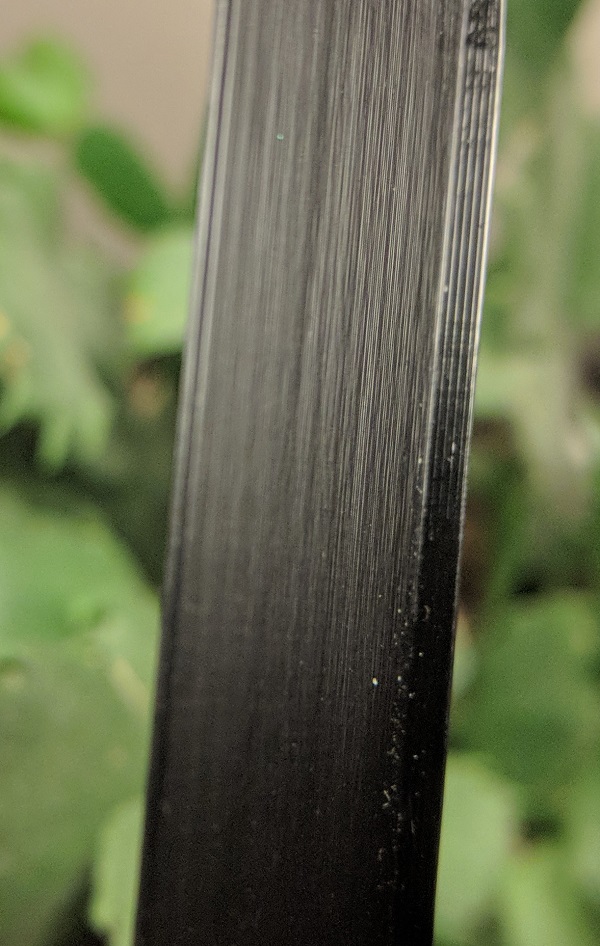
sneaky-tricky
on 19 Apr 2018
I am having this very issue on mk2.5 version also.
 CacikeOtoao
on 19 Apr 2018
CacikeOtoao
on 19 Apr 2018
@ericclinedinst , did you mean to post that here, I don't see how it's relevant to this topic?
vertigo235
on 19 Apr 2018
Oh I see, you were trying to check on the status of the 2.5 that the dev above mentioned, he told you to email him directly. I'm not sure why you would subject yourself to firing up a chat with a first tier support representative if the dev offered to correspond with you directly.
vertigo235
on 19 Apr 2018
Way off topic but had to correct a statement.
@devilhunter84
Not sure why you claim the Zairibo MK3 to be made of MK2 parts with some MK2.5 parts. There are conversion kits for each version you are planning to convert, with the printer you are converting being the key for which parts you end up on your Zaribo.
Back on topic, however I agree the parts are the same that can be sourced from PR, besides the Misumi parts. Some of the plastic parts are changed but seeing how users here tested it with all kinds of extruder setups and apparently replicated the results, one can assume the issue is not related.
 vkojchevski
on 19 Apr 2018
vkojchevski
on 19 Apr 2018
@vkojchevski
The MK3 kit he sells now upgrades a normal MK3 to a Misumi Frame.
The MK3 kit he sold a couple a weeks earlier was an upgrade for a normal MK2 to a MK2.5 with +12V Magnetic heatbed +Bondtech gears, also called MK3.
I ordered a couple of spare POM nuts of him two months back, and they never came. Canceled my order last week.
devilhunter84
on 19 Apr 2018
A 2cm^3 cube I printed:
0.1mm
vase mode, one layer width
no top no bottom:
Slic3r prusa mk3 default speeds
Firmware: 3.1.3
Material: Smart materials PLA at 210º
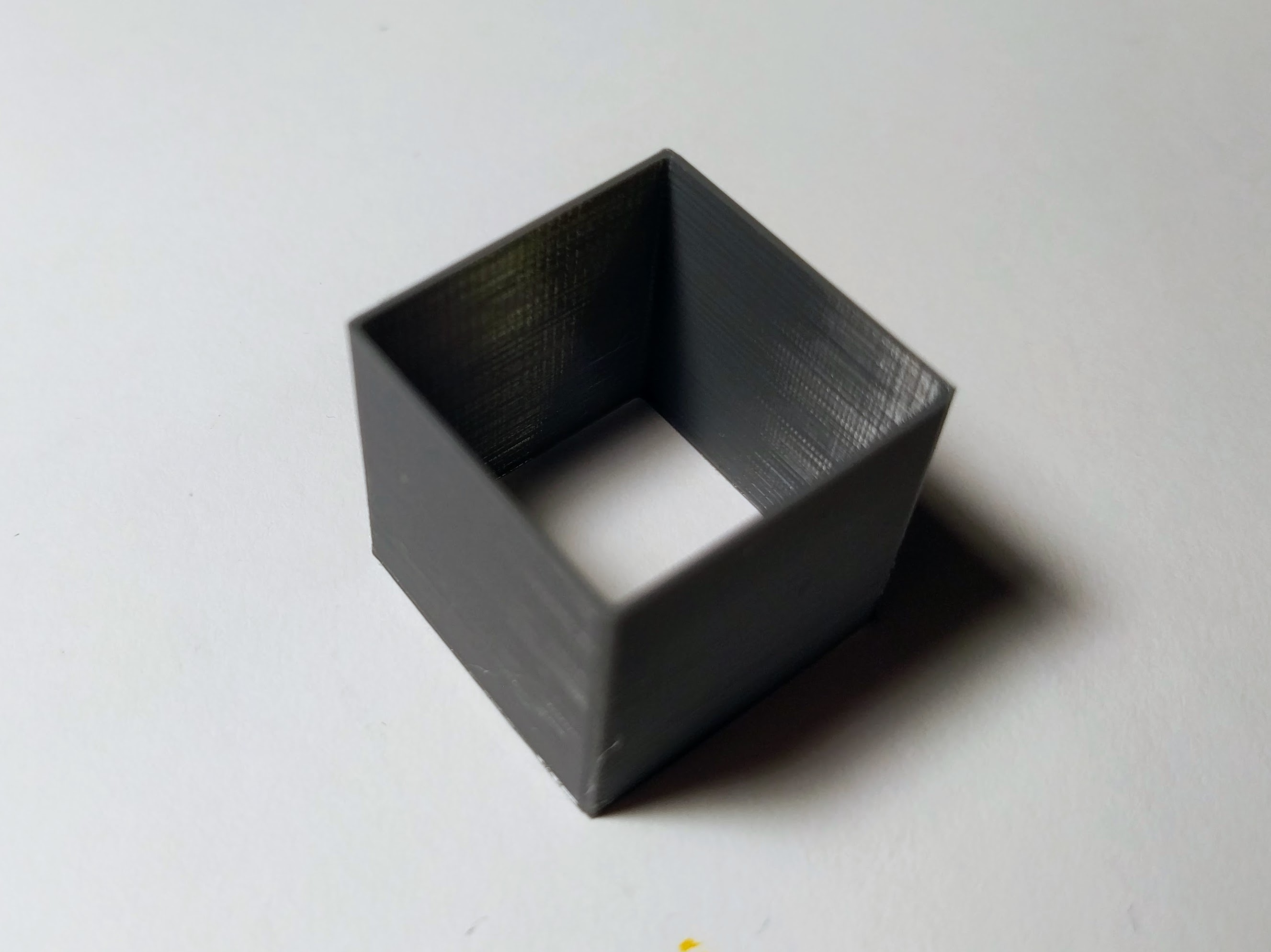
 MiquelAdell
on 19 Apr 2018
MiquelAdell
on 19 Apr 2018
@devilhunter84
Strange, because none of the kits actually include any parts like the bed, end stops, extruder etc. You might have mistaken the MK2.5 printed parts with a wrong label MK3, which in fact now all of the versions use more or less the same parts as an attempt to reduce file versions and some wrong labeling might have happened. You use the same printed parts in your custom setup even though you use different extruder (didn't pay attention to the board and bed), point being they can be used for different versions. About the shipping and your order, I am not affiliated with the shop so cant tell, but this isn't the place to discuss that, although I fully agree with your right and decision to cancel a 2 month old order.
Sincere apologies for the off topic, won't drag it on further than I have.
vkojchevski
on 19 Apr 2018
Has anyone in this thread sent their printers back for study?
HeySideburns
on 20 Apr 2018
Is there anyone who can modify the mk2.5 and/or 3 firmware such that it will work with said mk2.5/3 but without all the features unique to the mk2.5/3 so that it’s basically the mk2/2s firmware? That way we can test all those possible firmware culprits in one go.
Maybe the better way is to start with the mk2/2s firmware and introduce the minimum necessary aspects of the mk2.5/3 firmware changes (such as bed mesh levelling for mk52) and test from there.
MTJC
on 20 Apr 2018
@bubnikv
I had a theory, that the Inconsistent extrusion would be a consistent pattern 1 "full step" long.
https://image.ibb.co/f2tuz7/0420180011.jpg
This part was printed changing the current from 20, 30, 40, 50, 63, approx every 5mm in height. (object is about 30 mm tall) EDIT: Using the M912 command.
The results were unexpected, but not fully surprising to me. What I am interested in talking about is specifically the top 5mm. (0.2mm layer height, so about the top 25 layers)
Notice how "consistent" the pattern repeats itself. About every 4mm. (and my math says, that is about 1 full "step", or 32 microsteps)

If we look at this closely you can see the pattern is VERY consistent.
I am not great at reading code, but I will go on a limb, and guess, that something in the code for the drivers is is assuming there are 16 "weak" micro-steps, and 16 "strong" micro-steps, which causes the repeating cycle every 32 micro-steps, or 1 "full step". Whatever controls this, is not tuned properly.
PS: This is not "inconsistent" extrusion. This is "Consistent BAD" extrusion.
 kwaad2
on 20 Apr 2018
kwaad2
on 20 Apr 2018
Hej @kwaad2! Very interesting! How do you increase the amperage every 5mm? And what unit are these numbers in? It cannot be A...
stahlfabrik
on 20 Apr 2018
@kwaad2 Brig here, thanks for posting that here.
Have you tried this with the latest firmware and Settings > E Correct set to 1.100 (the recommended starting point)? The pitch of those is the same as the general moire we're seeing, we're just seeing that moire PLUS random fat lines. Do you think the current boost fixed stepper motion enough to get you down to pure moire? :)
Also, what method did you use to adjust current on the fly like that?
Thanks!
TheBrigandier
on 20 Apr 2018
I used "M912 Exx" followed by "M910". I could have scripted it into Slic3r, to do it automatically. (temp-tower-style) But I just punched it into the terminal every ~5mm.
This was tested running 3.2 RC1, E-correct OFF.
I'm warming up the printer now to test @ 1.100
I think the "random fat lines" are a different problem, as they are quite "random" and once I got my filament "dialed in" they are not "common". (I'm not saying they don't exist, because they do. Just not sure where to point blame)
If you do notice though on the lower lines in that print, there IS occurance of your "fat lines", which makes me think the motor is "struggling". I always print HOT, and keep my filament "thin". I find much more occurances of "Fat Lines" when printing "cool"... which makes sense that decreasing the amperage at the same temp, would show the same symptoms. If that's the case, the only solutions I can think of would be to increase amperage on the motor. (which is likely to cause heat failure on the extruder assembly), increase printing temps, or, get a geared extruder.
kwaad2
on 20 Apr 2018
@kwaad2 Looking forward to seeing the E-correct 1.100. You might try a few away from that too, 1.120 or 1.080, little adjustments on this make big changes.
If amperage is enough to fix the fat lines, then this is pretty much one of the two problems down.
TheBrigandier
on 20 Apr 2018
@kwaad2
The TMC2130 work OOTB, but have a programmable custom driver table, for individual application and use.
My guess is that Prusa Research did not program a custom driver table for the steppers, and this results in an unoptimized step timing which explains the consistent fat layers.
The inconsistent fat layers are a result of another fault somewhere, definitely related to the ticket i opened with the Z axis going up and down during every print. (if not solely responsible)
Ticket #638
Also there are 16 'strong' steps and 16 'weak' steps, because there's 16 upwards going steps in the sine wave, and 16 downwards going steps in the sine wave.
I think the pattern will go away if they set the custom driver tables right.
Also the TMC2130 can switch from StealthChop to SpreadCycle on the fly, which we also don't have in the Prusa firmware.
It's either Quiet Mode (StealthChop) or Normal Mode (SpreadCycle with StallGuard)
Another implementation that's missing, because the TMC2130 are so new. (correct me if i'm wrong here)
Build date 2014, but this is still new, compared to the very old stuff we've used before.
I think the devs here (no offense) were just happy they could get the board to print, and management said that's good enough for now. Optimizing usually happens in the field.
@ff8jake
The stepper driver amperage can be set with
Initialize settings:
M910 - Reset and initialize the TMC2130 chips.
Most setting changes won't go into effect until this code is sent.
Current settings:
M911 - Holding current
M912 - Running current
Set the above TMC2130 currents. Must be given in current scalar values (0 to 63).
Example: M911 X14 Y20 Z30 E36
Display settings:
M913 - Print the currently set TMC2130 current values
It's what metacollin wrote here:
https://shop.prusa3d.com/forum/-f23/einsy-rambo-on-mk2--t6137-s40.html#p75501
Someone on the forums suggested against using this code because it may damage something, but that's bull.
I've personally tried it and can get the x and y axis to skip at X5 and Y5, and to press harder against my hand at X20 and Y30 than stock current.
Geared extruder motor works better with higher current anyway, so i'm using 40 for now.
devilhunter84
on 20 Apr 2018
@devilhunter84 you are now tied with @stahlfabrik for my favorite person on Github.
That 0 to 63 clarification is something I have looked for for a long time. I know that there's a vsense setting that changes when going beyond 31 as well, per Prusa firmware comment (might only apply to certain axes).
TheBrigandier
on 20 Apr 2018
@ff8jake
So, if i can find out how to program the custom driver table for the TMC's i can surpass @stahlfabrik ?
That's setting it a bit high, but i accept. Will look into it on the weekend (no promises though)
Also now that we see it via @kwaad2 's experiment, more power to the stepper drivers is usually how you get to smoothen out things, it's just bolting over the problem with moar power.
It's a hotfix, but not the solution we are looking for.
devilhunter84
on 20 Apr 2018
@ff8jake
I messed around with this previously, it's the TMC2130 calculator (look at the microstep table)
https://www.trinamic.com/fileadmin/assets/Products/ICs_Documents/TMC5130_TMC2130_TMC2100_Calculations.xlsx
Also the manual: (page 78)
https://www.trinamic.com/fileadmin/assets/Products/ICs_Documents/TMC2130_datasheet.pdf
devilhunter84
on 20 Apr 2018
@ff8jake
I tried printing it at 1.100 and 1.080, and there was ZERO change in the spacing. I'm gonna rule this out as a "cause/fix"
@devilhunter84
I'm sure it was me. (Sean.H8) that was saying that. And after printing for 5 minutes with max power, locked at 30mm/s (slow)... I can tell you. You can EASILY melt the PETG on your extruder assembly.
My Stepper was already getting near 40c, and it was COLD at the start of that print. I don't doubt the stepper driver's ability to handle it, I don't doubt the motor's ability to handle it. I doubt what the motor is bolted to's ability to handle it. (I'm sure if you put a heatsink/cooler on the motor, it would be fine... but that would fit under my "know what you are doing" clause)
kwaad2
on 20 Apr 2018
@ff8jake @devilhunter84
I had to LOL hard! You guys are awesome.
The more users we see mentioned in the release notes the more happy I am.
Open source for the win!
stahlfabrik
on 20 Apr 2018
I wonder if one could ask trinamic for their opinion of the matter. I am sure Prusa devs are in contact to discuss those matters, or at least I hope:-)
Also I wonder how the full bondtech extruder from bondtech are build. Are they geared?
stahlfabrik
on 20 Apr 2018
@stahlfabrik
Modern Bondtech versions are usually combined with a planetary gear stepper:
https://lh4.googleusercontent.com/-1KdjmAG6gzg/VFZPXLjlHII/AAAAAAAAAwM/huyKuV2aQCU/w2048-h1150/Bondtech%2BExtruder%2Bopen.jpg
Other than that, there's no big wheel like in the titan.
Which i don't understand, because planetary geared steppers are really weak, and that makes the only advantage of the bondtech the super grip from both sides.
Not using a normal NEMA with high currents means it does not force the ever-living-cr*p out of the filament into the nozzle, like the Titans or the Wade's do.
Older Bondtech's (like the V2) had usually normal steppers.
Edit: ok, some lower geared planetary gear steppers can go up to 1.7A, the high geared ones, are usually way below that.
edit 2: found some high geared ones with high current. well ok, scratch my comment. (well back in MY day...) Only difference is weight compared to a normal stepper. You would mount this to an Ultimaker or a CoreXY, not throw this weight around on a direct drive Cartesian.
devilhunter84
on 20 Apr 2018
@devilhunter84 I have seen some people comment that one of the biggest issues they have with Bondtech is stripped filament. Think they went the planetary route to make it easier for the stepper to skip if there's an issue?
TheBrigandier
on 20 Apr 2018
The Bondtech BMG uses their dual drive gears and includes a large diameter gear for a 3:1 ratio like the Titan: http://www.bondtech.se/en/products/extruders/bmg-extruder/
zafuquazar
on 21 Apr 2018
@zafuquazar
Ah, the BMG Version uses a pancake stepper and a big 3:1 gear in favor of the planetary gear stepper. Thanks for the heads up! Now this should fly on the X axis.
devilhunter84
on 21 Apr 2018
@ff8jake
Do you know where to set the TMC_DEBUG value in the firmware? It should be somewhere in configuration_adv
I keep stumbling over gcode M122 which outputs stuff like set/measured motor currents and timings, also some driver registers.
Gcode i found so far for the Prusa Firmware TMCs:
M910 - Reset and initialize the TMC2130 chips.
M911 - Holding current
M912 - Running current
M913 - Print the currently set TMC2130 current values
M914 - high power mode.
M915 - low power mode.
M916 - Set stallGuard threshold
M917 - Set PWM amplitude
M918 - Set PWM gradient
Interestingly, the some normal Gcodes in the Prusa firmware do something completely different to the TMCs than documented in marlin.
Marlin:
M122 - TMC debugging (with S0 or S1)
M906 - motor current in mAh
M906 S1 - Start adjusting current
M906 S0 - Stop adjusting current
M910 - Commit digipot/DAC value to external EEPROM via I2C.
M911 - Report the TMC stepper driver overtemperature pre-warn condition to the host.
M912 - Clear the stepper driver overtemperature pre-warn condition flag.
M914 - TMC Bump Sensitivity
btw, if anyone's interrested, we should open a topic in the forum for the TMC driver discussion, there's a lot.
Also there's no documentation of this anywhere that's easily obtainable.
devilhunter84
on 21 Apr 2018
@kwaad2 Could you please elaborate on the math that makes you conclude 4mm is 1 full step?
I am trying to reproduce that but I a different length for h=0.2mm and w=0.45mm and esteps=161.3
Thanks.
misan
on 21 Apr 2018
I made a page on the forums about all info i can find about the TMC2130:
https://shop.prusa3d.com/forum/hardware-firmware-and-software-help-f64/tmc2130-driver-infos-and-modifications-t15835.html#p79147
As far as i see, implementation and improvement of the TMC2130 halted when Marlin could get those to print, and they made a TMC bugfix version some time after that.
These are by no way optimized.
If anybody has any relevant info or wants to tinker with me on the TMC2130, be my guest.
devilhunter84
on 21 Apr 2018
How does the TMC2130 theory fit together with the fact that the Mk2.5 has the same print surface quality problem?
 udvlp
on 21 Apr 2018
udvlp
on 21 Apr 2018
@misan Why are your e-steps per-mm not at 280?
Anyway.
0.2 * 0.41 * 1=0.082 cubic mm, per linear mm of travel. (give or take a touch)
pi0.85^2 * 1 = 2.269 cubic mm, per mm of filament. (give or take a touch)
2.269 / 280 = 0.0081 cubic mm per microstep
0.0081 * 32 = 0.2592 cubic mm per FULL STEP
0.2592 / 0.082 = 3.16mm of linear travel per FULL STEP
When I measured it I got ~3.8mm per "repeat of cycle". I know my numbers don't match up perfectly, but they are close, and I know I run a 0.97 extrusion multiplier, and I don't know how much the Mk3 reduces it in firmware, (recall the old over-extrusion issue, they fixed with firmware?) So if it dropped another 0.95, that is about a 10% drop in extrusion, vs "math" and that would bring my math's 3.16mm of linear travel, to right around 3.6mm of linear travel... This is strikingly close to 3.8mm of linear travel.
kwaad2
on 21 Apr 2018
I forgot if I have already mentioned the observation that the square at the first layer calibration is not really a clean square. Every forth line sticks out a little to the left.
I think I wrote that already and now I found an unrelated forum post that quite nicely shows that.
To be honest. I have not yet looked at the embedded gcode yet to see if it is meant to be like that.
It also might have nothing to do with our problem.
So just FYI: here is the post with the pic: https://shop.prusa3d.com/forum/hardware-firmware-and-software-help-f64/problems-with-calibration-stringing-t15495.html#p76377
stahlfabrik
on 21 Apr 2018
@stahlfabrik I saw this and was able to fix it by changing seams from "nearest" to "aligned". Maybe some type of variance intended to make the seam less visible?
TheBrigandier
on 22 Apr 2018
@stahlfabrik disregard that, thought you were talking about the bulge at the corner of the test cubes.
TheBrigandier
on 22 Apr 2018
@kwaad2 Wrong esteps was the cause. With 280 steps/mm I get 3.38 mm of length for width 0.45 mm and height=0.2mm. I see you use width 0.41 mm. Is that what your are printing at?
For 0.41mm width and 0.2mm layer height I get 3.74mm of travel, which is pretty close to your 3.8mm measured distance.
(32/280)*32.76mm_out/mm_in
I am using Slic3r flow math http://manual.slic3r.org/advanced/flow-math
Thanks a lot for the details.
misan
on 22 Apr 2018
@misan I actually print at 0.45 width, I just picked a random number that would yeild approx the same total extrusion as the proper math.
0.410.2 = 0.082
((0.45-0.2)0.2)+pi((0.2/2)^2) = 0.08141
0.8% off... sue me. 😄
I just know from experience working on CNC machines, that a pattern that repeats that consistently regardless of speed, is always caused by a "cycle".
Once per rotation of of the stepper motor? No? Rule this out.
Once per rotation of Bearings inside the stepper motor? No. Rule this out. (I think it's a bushing, but even it it was bearings, it would be a much "slower" pattern. (maybe 20mm of linear travel)
That's all the "mechanical" goodies ruled out, all that is left is the motor itself, or the software controlling the motor.
I know there's a "loop" that controls the microsteps, This loop, is within 20% of what I measured. This is WELL within the "margin of error" of my measuring. (It's super hard to see/measure that. And it would take a mitutoyo measuring microscope like we had at my old job, to be able to measure it accurately)
I did see something mentioned that rings WRONG with me though. And this bothers me.
I thought the MK2.5 had a Einsy board as part of the upgrade. I noticed today, that it does NOT. The fact the Mk2.5 has the SAME PROBLEM, makes me scratch my head, and it makes me think looking at the Trinamic is not correct.
I still think the problem lies with the microstep / full step... but I think it's not the Trinamic. (as if it was the Trinamic, why would the mk2.5, which does NOT have the Trinamic have the same issue!)
kwaad2
on 22 Apr 2018
@kwaad2 @udvlp (and anyone else I may have missed) thank you for re-highlighting what appears to be the elephant in the room....the MK2.5 that has no Einsy and yet suffering the same issue.
This should be more than enough to happily rule out the Einsy Rambo components (e.g. Trinamic TMC2130 stepper drivers) as a possible culprit, right?
I'm not a software guy so what I say may be an obvious non-starter to the software guys here but what if someone could take the mk2/2s firmware (the latest that is known not to have this issue if any of them do) and then modify it such that the barest of essential changes needed for the MK2.5 (or MK3) to work are included only. If I'm not mistaken, that should just be the mesh-bed leveling process that is slightly different for the MK52 heatbed vs the MK42. No need to worry about e-steps (can be adjusted via eeprom manually) nor fan rpm monitoring or any other non-essential aspect of firmware designed for the MK2.5 and MK3.
Surely such a test would be useful, right? Multiple birds, one stone approach to possible (firmware) culprit elimination?
Edit: Just remember Eric telling me the fan would need changing though. So one would need to have a spare mk2/2s fan or buy one (i'd be willing to for testing this in the hopes we can nail the culprit) so that we can rule out that aspect of change to the firmware also (if need be). Would need to design an adapter for it to fit on the mk2.5/3 x carriage though but that's easy.
MTJC
on 22 Apr 2018
@kwaad2 If you consider 1.75mm filament diameter instead of 1.7mm you'll bump up the length another bit (from 3.58 to 3.74mm in my math @0.41mm layer width) but maybe your filament was actually 1.7mm.
However, I have been thinking about the pattern, as you say 16 "weak" steps and 16 "strong" ones. The weak steps will mean there is less angle traveled for each microstep due to less torque available while the strong ones would compensate traveling more and, therefore extruding a thicker path than the wicker ones.
We could relate that the TMC2130 linearity correction table (but that one defines only 90 degrees and not 180, so I do not see how the effect could be so). And then there is the MK2.5 showing the pattern too. [Which I am not yet sure whether is similar or not.]
So, yet another theory could point to the steppers themselves: Do you think some steppers could be the culprit?
misan
on 22 Apr 2018
@misan ooops... Yup. 1.75. That's exactly where my math was wrong... :)
Yeah, that level of math regarding the correction table is above me. I would have to read up on that for a good 2-3 days to even begin to understand it. :(
I don't think the steppers could be the culprit. The fact the 2.5 upgrade has it, whereas they did not have it before, proves it is a "software" change.
@MTJC One way to verify if it's a "sense" issue. (eg, fans, probes,sensors,polling,etc) Would be to print half the cube at 100% and the other half at 75%.
if the "moire" pattery remains the same, that would rule out the "polling".
kwaad2
on 22 Apr 2018
@kwaad2 If we go to the software side, then it would mean some pulses are delayed just a bit (during half of the step) while others have the right timing. And because I cannot see the same precise pattern you showed us in all the pictures, it could be the case that this delaying of some of the step pulses is happening with a repetition cycle different than a full step sometimes.
Things like that can happen whenever firmware has a critical section (disabled interrupts) that can add up to the precise stepper timing.
misan
on 22 Apr 2018
@misan posted by devilhunter on the forums.
https://shop.prusa3d.com/forum/hardware-firmware-and-software-help-f64/tmc2130-driver-infos-and-modifications-t15835.html
I did a..
M912 E63
M910
That sets the driver to max power, and it makes the pattern "distinct".
Just make sure to turn it off/reboot the printer after doing the test. I don't think the PETG extruder could handle the heat on a full-size print. I've ran it for ~10 minutes, with linear speed @ 30mm/s, and it was fine. But I would be cautious with linear speed at 60+, for extended periods of time. (Totally fine for "slow" and "small" test prints though)
kwaad2
on 22 Apr 2018
@kwaad2 @devilhunter84 beautiful piece of information. Thanks for sharing it.
We are proposing two possible causes of uneven extrusion:
- uneven micro stepping causing the strong/weak micro steps (blame driver electronics)
- bad extruder step signal timing caused by the firmware and introduced as it evolved over time (blame firmware)
Maybe both are happening, I do not know.
Testing the latter would require using a logic analyzer to check the timing of the extruder step signal and look for uneven delay steps (outside of the ramping up/down part).
misan
on 22 Apr 2018
Any difference seen with / without linear advance?
 thinkyhead
on 22 Apr 2018
thinkyhead
on 22 Apr 2018
Good to see you Thinkyhead! Thanks for chiming in :) As far as I can remember, without re-reading everything, this has been tested both with and without LA and it doesn't make a difference. Has been tested with and without mesh bed levelling as well.
c-stewart
on 22 Apr 2018
As an aside, I've been emailing back and forth with Blas from Prusa support. He had me do the standard troubleshooting process for "inconsistent extrusion" in an attempt to solve the issue. He had me install 3.2.0rc1 (which I already had, and I had tuned e-correct as well), then he had me do a bunch of cold pulls, try different tensions on the bondtech screws, check that the gears are rotating properly, and that the gears, plastic piece and ptfe were properly aligned, then he had me pid at 220, then turn up the layer fan and check that the rpms are up at 4500, then checked live z, then disabled filament sensor, then I ever replaced the ptfe in the hotend, and the nozzle to new ones. No change. (not that I really expected one.) Here's a pic of my test print after all of that.
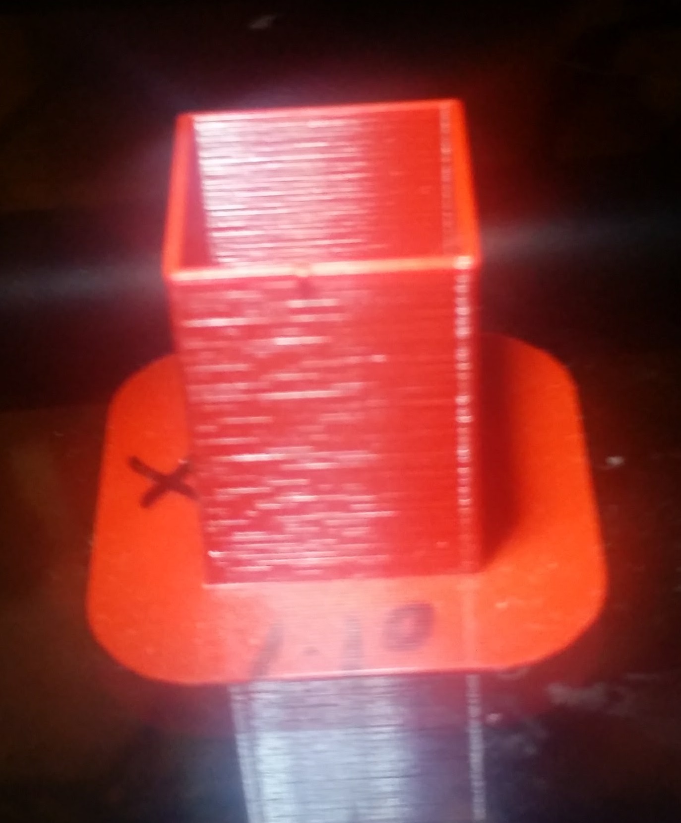
c-stewart
on 22 Apr 2018
Oh yeah, @thinkyhead , definitely not LA as this issue was still present in their last firmware version that had LA turned off
c-stewart
on 22 Apr 2018
Interesting forum post. 999% speed fixes the
Edit. Wrong link
https://shop.prusa3d.com/forum/hardware-firmware-and-software-help-f64/print-quality-and-a-possible-clue-t15853.html#p79278
stahlfabrik
on 22 Apr 2018
@stahlfabrik Makes me wonder, think we're running into an issue with X and Y not moving correctly? It would simulate an extrusion issue, as the nozzle may linger longer in some areas than others?
TheBrigandier
on 22 Apr 2018
Not very surprising. Just fits to the "happens due to friction / pressure effects inside the hot end" theory I have.
At max. speed (most likely <999% due to processing power) the nozzle pressure is very high. The higher the nozzle (back) pressure, the lower the effects due to friction for example inside the heat brake. It just doesn't matter any longer if the semi-molten filament sticks to the walls for a short time before breaking free, the flow through the nozzle is already at it's maximum and this small changes will have no visible effect any longer.
PS: I know the same explanation fits to unequal extruder stepper due to FW or whatever else.
Sebastianv650
on 22 Apr 2018
@Sebastianv650 Friction / Pressure effects in hotends is an area I have very little experience in. If this in fact what is causing it, what are the solutions? Another type of hotend? Different extruder design? Is there a way we can test this theory with just the hardware we have?
Just trying to think up ways I (and hopefully others) can help test this.
TheBrigandier
on 22 Apr 2018
Well. High x y speed also mean high e speed and pressure.
Any volunteers on reproducing that result? I cannot print for a few days.
stahlfabrik
on 22 Apr 2018
The hotend design is several years old and very proven. I really doubt that has anything to do with this issue.
vertigo235
on 22 Apr 2018
Oh and I cannot believe the hotend is the problem. Not a genuine E3D v6.
stahlfabrik
on 22 Apr 2018
Higher print speeds means the exruder motor is moving faster and may need less microsteps correct? It's almost like when you add gears it doesn't have to creep along in fractions of a step.
vertigo235
on 22 Apr 2018
And i thought it was just me. Since i have two self sourced MK3's i'm having a bit of trouble finding errors that are homegrown due to different hardware and errors that currently come from the firmware.
My X axis currently hates me, it's vibrating a lot more than the Y axis, and you can i definitely feel the X motor vibrating more than the Y motor.
This causes some weird stuff like this here:
https://imgur.com/a/CzqAehs
Y side looks fine, X side looks slightly borked (only when the light shines from the top.
Spent the whole day today swapping motors, swapping threaded rods and nuts, swapping bearings, swapping linear rods, tightening and loosening various screws and messing with motor currents.
If i speed up the external perimeter speed to 170mm/s or 200mm/s, and increase the motor current a bit, the lines on the x axis are gone.
I'm using 17HS16-2004S1 motors from OMC motors btw, not the LDO motors that the original Prusas use.
devilhunter84
on 22 Apr 2018
Well, I don't get the intresting wavy pattern shown by pictures here on my MK2 (E3D v6) and TAZ5 (hexagon). But I know the effect that some lines look wider than others as shown in my microscope cut picture somewhere above. As this one is quite a common thing, I would expect the wavy pattern is just something like an extreme version of it.
I don't know how to change this effect with given hardware, but I'm quite sure it's found in the solid->molten transition zone.
Sebastianv650
on 22 Apr 2018
@devilhunter84 @ericclinedinst Are both of you using that noctua to cool the e3d? Think there's a possibility it's not cooling as well as the extruder fan on mk2s? I remember hearing some type of special fan needs on the Einsy.
TheBrigandier
on 22 Apr 2018
@stahlfabrik @Sebastianv650
I agree with Sebastian. Basically you are just cramming so much "pressure" into the nozzle, that it will "balance" out the spray.
For example: If you take a piston water pump, (such as most pressure washers) and spray, you will find the spray is "smooth", this is becuase of the "pressure" in all the hoses/lines, as everything "expands and contracts" to make it smooth. IF you were to remove the "hose" from the pump, and have the pump just "pump into the air", it would have an extreme "chop" to it. All 3D printers actually already kinda have this "chop" except, we are experiencing something else. But Yes. Print faster, get smoother results. The question is, "is the pattern the same". I can BARELY see the pattern on my 3.5:1. Does that mean it's fixed? No, it's not. It's just less visible. (I however am unable to "test" because it is so impossible to see)
I will do a print later tonight, and ATTEMPT to measure the "spacing". If, by some chance I can see it enough to measure it... It will confirm if it's Extruder or XY.
kwaad2
on 22 Apr 2018
To rule out that it is x and y one could also create a profile that maxes out the e3d v6 capacity. Like the 0.3 profile that was removed from slic3r.
So that would also be a nice addition to the 999% speed test
stahlfabrik
on 22 Apr 2018
@ff8jake
yes, i'm also using the 40mm noctua from Prusa. But it's the same rotm 5v noctua you can get off Amazon.
Think there's a possibility it's not cooling as well as the extruder fan on mk2s?
Definitely. The MK3 cools the E3D heatsink way slower than the 30mm fan on the MK2, resulting in the many clogs the Users report on the forums. The 30mm fan has a 30mm output hole on the MK2, resulting in a optimum airflow and cooling, and the 30mm fan can cool the heatsink down from 200 degrees much quicker. The MK3 on the other hand, uses a 40mm fan (that has way less static pressure than the 30mm fan) on a output hole that is also about 30mm from what i can see on the Prusa Extruder STL files. This decreased air outlet hole blocks around 1/3rd or 2/4th of the air outlet the Noctua can actually provide.
This results in clogs on the MK3 when printing slow and below 205 degrees, because the heat will creep up and cause a filament jam in the teflon tube. The MK2 could print PLA slow and at 180 no problem, because the bitey 30mm fan airflow was not blocked in any way.
The Mk3 is a slight regression in terms of hotend cooling, and the Noctua was chosen mainly because of the quietness and the RPM signal.
But i thought this was common logic? Decreasing the air outlet of a fan in any way will create air vortexes and back pressure; i think decreasing the air outlet hole by 1/3rd will decrease the actual air flow by 2/3 or so.
(E3D recommends a 4-5 CFM airflow for minimum cooling, i think the 40mm Noctua with it's outlet airway barely gets it done)
This can only be measured by expensive equipment, but we can measure this in a much simpler way.
Crank up the nozzle heat to 220 degrees and measure the time until the hotend fan switches off.
To back my numbers up a bit: (also i have a Sunon 30mm fan on my MK2, so not original anymore)
My custom MK2 220 to 50 degrees: 8 min 10 sec
My custom MK3 220 to 50 degrees: 11 min 5 sec
Since we're slightly off topic with the air cooling, could you measure your original Hotend cooldown time? Then i have a reference point in how my Titan with the custom Noctua mount currently stands 😀
I doubt that the E3D hotend or it's cooling has anything to do with our extrusion problem.
The question is if there are multiple problems are work here that show slightly similar results, like some new algorithm that also affects MK2.5 movement, combined with the TMC driver problem on the MK3.
It's somewhere in the firmware of the MK3, and something else came from the MK3 backport fork to the MK2.5
Ok, i can't seem to word the last two sentences right (non english speaker here), but you know what i'm trying to say.
devilhunter84
on 22 Apr 2018
If the hotend would be „on the edge“ of clogging non stop for some users, then the flow would reduce, pressure build up, explode the beginning clog away and it would repeat.
That would be quite random and also would lead to phases of less flow followed by sudden more flow.
I like that theory.
Would also explain why some people have it, some do not (variances) and why it may come when changing from MK2S to 2.5.
And with high speed and pressure there is less clogging
stahlfabrik
on 22 Apr 2018
@stahlfabrik You're picking up what I'm laying down. At this point I am wondering about wiring up an "alternative cooling solution" with a bit more oomph behind it and just seeing the effect...
TheBrigandier
on 22 Apr 2018
@stahlfabrik @ff8jake
Just sayin', ineffective hotend cooling results in sporadic missing layer lines (soft clogs), random small filament blobs at outer walls or clogs at prints with lots of retractions (hard clogs) or low filament temperature, not perfectly repeating patterns.
devilhunter84
on 22 Apr 2018
@devilhunter84 Yeah I got that, I'm ignoring the repeating pattern issue for now, more focused on obviously over/underflow layers like this: https://user-images.githubusercontent.com/8582658/38383035-07ca1e58-38d1-11e8-86e4-aa365c50e951.jpg
Here you can see under/over extrusion longer than the repeating pattern we're seeing.
TheBrigandier
on 22 Apr 2018
Throwing another theory in the room (feel free to shoot me down), the MK3 still has some wonky extrusion math.
From the prusaprinters blog:
We found a bug that caused under extrusion when using low layer heights (50 and 100 um) or tiny details together with extrusion multiplier (we use it in our drivers package). A rounding error while calculating the extruder flow was the culprit.
What was the result?
Some corrections on github, and this particular line in the start gcode:
M221 S{if layer_height==0.05}100{else}95{endif}
This forces the MK3 to set the extrusion multiplier to 0.95 for every print above 50 micron. You can see it in the Tune submenu of the printer.
I think a real fix looks different.
Also from the same prusa blog page:
in the second week of March will reintroduce Linear Advance and it will also bring linearity correction for the MK3 extruder. The idea behind it is that stepper motor with micro stepping doesn’t always move linearly but pulsates as it moves between the steps. This can create sort of moire effect on the object surface. New Trinamic drivers we use on the MK3 can be adjusted to compensate this effect.
Maybe the linearity correction is not fully baked yet?
devilhunter84
on 22 Apr 2018
@devilhunter84 Best I can tell, linearity correction is in place, it just works strangely. When I started playing with it back in 3.1.X, I was expecting it to adjust the width of the moire until it was "gone", kinda like when timing gets off on an LCD monitor. You can adjust the timing and the band gets wider and wider until it's just not there (in reality it got so wide that it's no longer visible). But in my testing, it's more like this (looking down from above onto an extruded line):
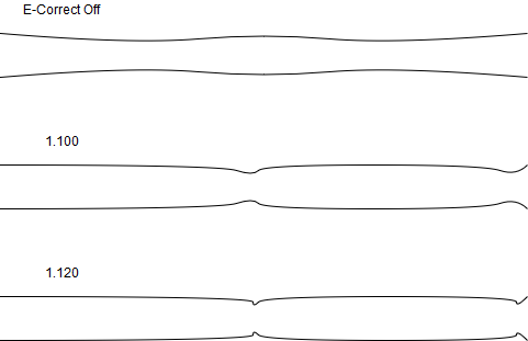
This makes it tricky to adjust. With it off, the "wave" is very apparent and smooth. With 1.100, it becomes a sharper "line" at the end of each length. If you adjust it in the right direction (but not too far!), that line gets smaller and sharper. I am yet to find a setting that completely gets rid of it though. If you go the wrong way (or too far), the effect gets smoother again. It's counter intuitive to say the least. Would be nice if Prusa would give some details on properly tuning this.
After seeing these effects, this is why I have a gut feeling that we're dealing with two problems. The "moire" issue that this adjusts, and the random filament under/over extrusion that affects an entire layer of a part.
TheBrigandier
on 23 Apr 2018
Noticed that these links didn't make their way over to here from the prusa forum. Thought they might be helpful.
VREF pot tuning fixed the problem for these people.
http://www.soliforum.com/topic/10108/ex ... nal-lines/
http://www.soliforum.com/topic/4759/new ... -problems/
http://www.soliforum.com/topic/9347/sol ... to-fix-it/
 nstis
on 23 Apr 2018
nstis
on 23 Apr 2018
Guys, I think I may have stumbled onto a variable. For a moment, look past the moire/repeating effect and consider it another issue. Full zoom required!
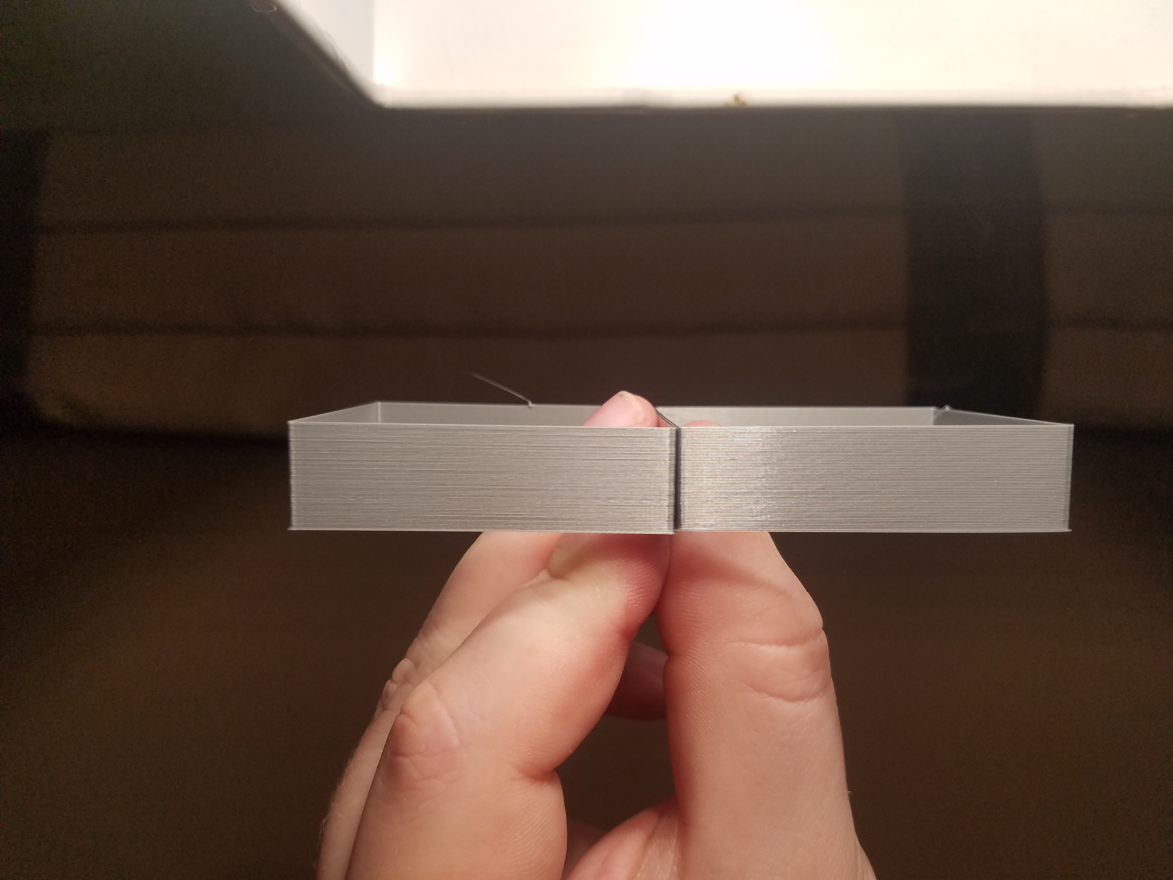
Both of these were printed with the same settings, with the exception that the left one has part fan ON, the right one has part fan OFF. On the left you can clearly see several layers sticking out, on the right they all look consistent (well, not counting moire). Can anyone with fat lines like this test and confirm?
TheBrigandier
on 23 Apr 2018
Well, that would explain why my PETG prints look better than PLA.
Skiidlive
on 23 Apr 2018
@devilhunter84
From the Prusaprinters.org: We found a bug that caused under extrusion when using low layer heights (50 and 100 um) or tiny details together with extrusion multiplier (we use it in our drivers package).
There were two issues going on actually, as usual.
First, the MK2 always had the number of E-steps set to 95% of the real value. We tried to implement an E-step calibration wizard, but then we found out, that if you entered the correct number of E-steps into the firmware, you would get over extrusion issues we had with the initial MK3 firmware. As this is difficult to explain, we rather disabled the E-steps wizard.
Somehow this exercise in E-steps calibration got forgotten, and we set the MK3 E-steps to the correct value at the initial MK3 firmware, which caused slight over-extrusion and shape deformations on sharp overhangs. So we decided to leave the number of E-steps set correctly for MK3 so we may run the E-steps calibration wizard in the future, however we decided to achieve the 5% under-extrusion with the M221 S95 G-code. All went fine, but one day we got reports that for thin layers the MK3 printer prints garbage. And indeed there was a rounding problem in the original Marlin, when the M221 S G-code was in action and the number was different from 100%. So we fixed that.
Now why our printers print best at 95% under-extrusion? I suppose there is an effect of a high plastic viscosity, which cannot easily fill all the air gaps between successive perimeters. To achieve reasonable shape accuracy, you have therefore to account for these tiny air gaps by extruding a little bit less.
bubnikv
on 23 Apr 2018
@akukan designed the Noctua design of the extruder body and he measured the temperature of the bottom part of the heat sink in various situations. We don't think there is a problem with nozzle cooling.
bubnikv
on 23 Apr 2018
@bubnikv
Thanks for the explanation.
Now it makes kinda why the MK2 had about 5% less E steps in the firmware than it actually had.
Stock firmware was E161.30 vs actual E steps of about E171.80, (that is 5% less steps) and extr. multi was set to 1 in Slic3r.
Calibrating the E Steps on the MK2 to E171.80 resulted in worse results than before, and after some fiddling i sasw that a general ext.mult of 95% in Slic3r PE worked great.
With the MK3 you did something similar, correct E steps but lowered EM to 95%
Might be good idea to include a technical section in the forum where some advanced users and some devs could write up what for example we explain here. All this gets lost in the Github ticket.
devilhunter84
on 23 Apr 2018
All this gets lost in the Github ticket.
... like tears in the rain.
misan
on 23 Apr 2018
@ff8jake
I haven´t been able to reproduce your findings on print fan On vs Off. Here are my settings and photos of results:
MK3, FW 3.2.0-RC1-461, E-correction set to 1.130. original kit with X-axis upgraded to R2/B6 parts+ added a E3D sock to the extruder.
left print gcode: testcode.gcode file from https://shop.prusa3d.com/forum/download/file.php?id=14443 - fan on during print.
right print: same file, but with the line ´M107 S255´ (print fan to 100%) changed to M106 (print fan off)
I see quite a big difference between the surfaces along the two directions in my prints.
Comparison of sides of the print where the X-axis is stopped/Y-axis moving, with light shining mostly through the print:
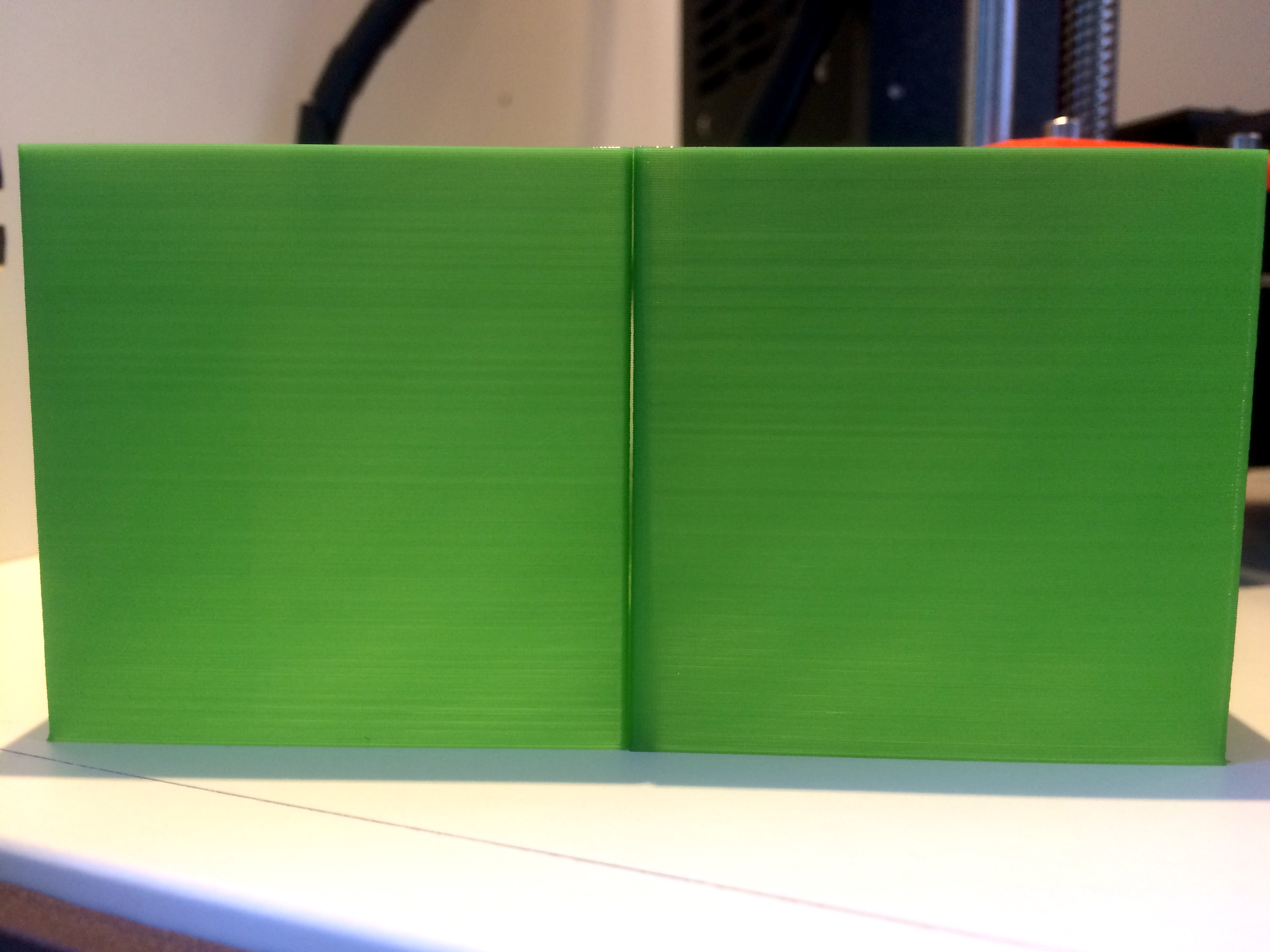
Comparison of sides of the print where the Y-axis is stopped/X-axis moving, with light shining mostly through the print:
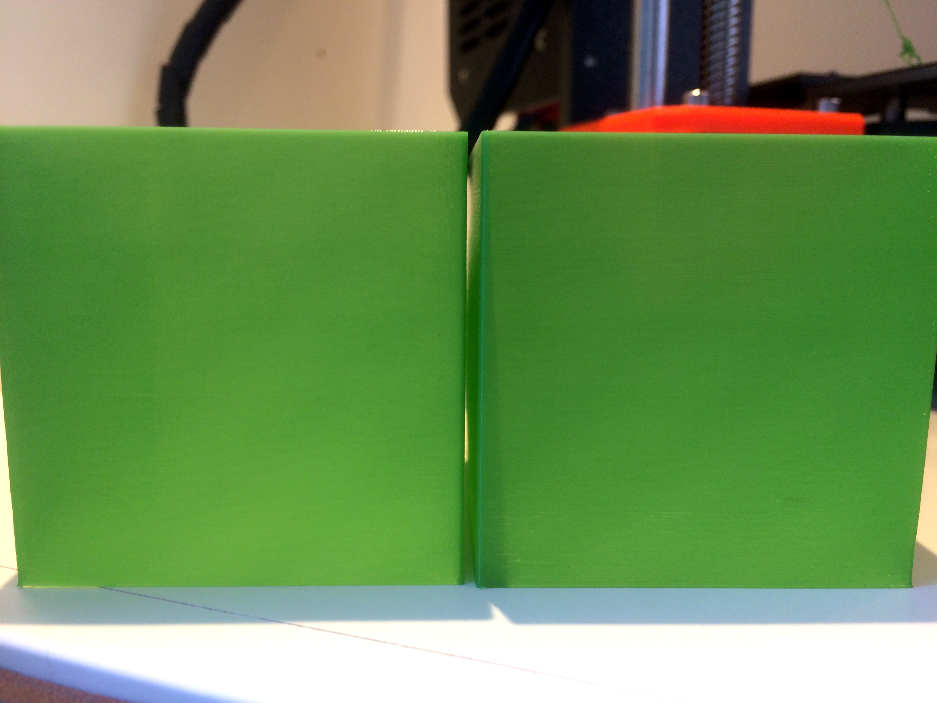
And here are two prints with the prusa gray PLA that came with the printer, with fan-off and fan-on, photographed along the different axes, with light from above as in most photos in this thread:
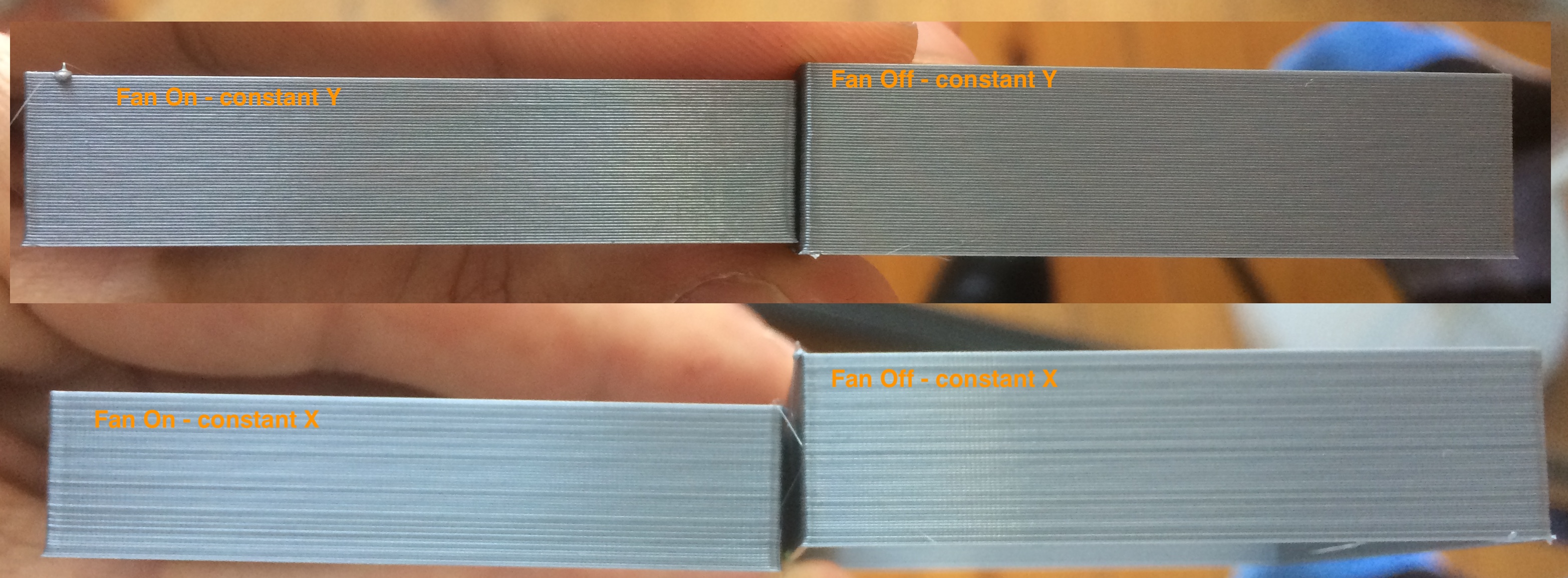
And the two prints side-by-side with light from above, each oriented along a different axis. 'Y-axis constant' on the right.
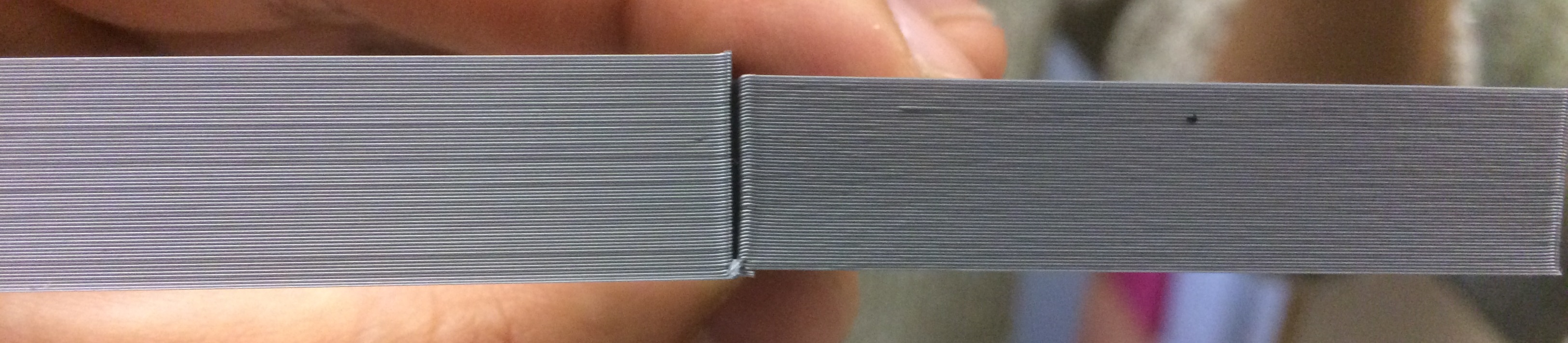
There is still some uneven extrusion on the right, but you really have to look for it to notice it.
Hope this helps. Does anyone else see a difference in print quality along the two axes? This problem might be specific to my printer, but more people might be running into it as well.
 fsilva
on 23 Apr 2018
fsilva
on 23 Apr 2018
pictures of the 'fan-off´green piece but with light glancing off the surface of the print, instead of shining through it as in the pictures above:
Y-axis constant:
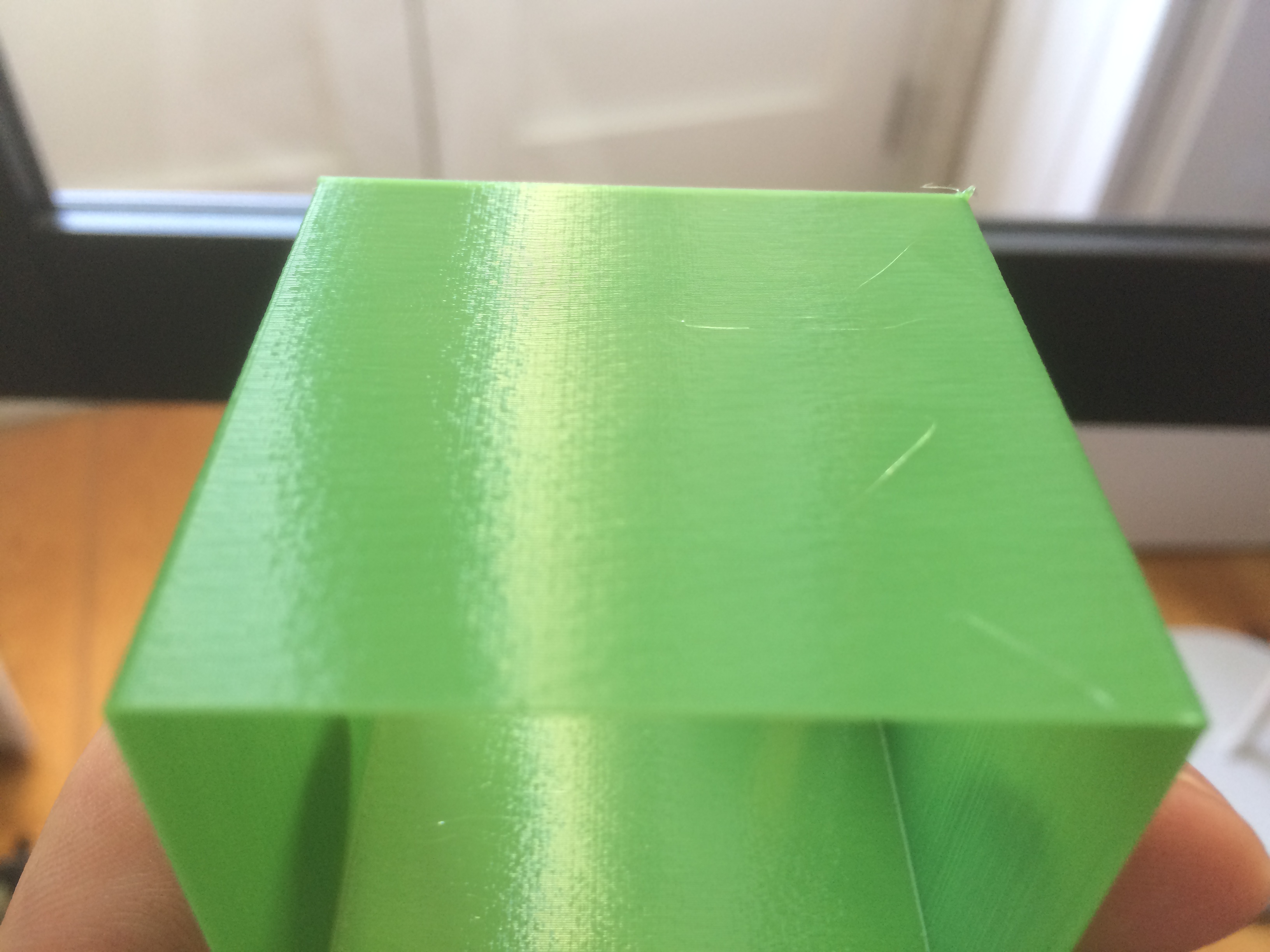
X-axis constant:
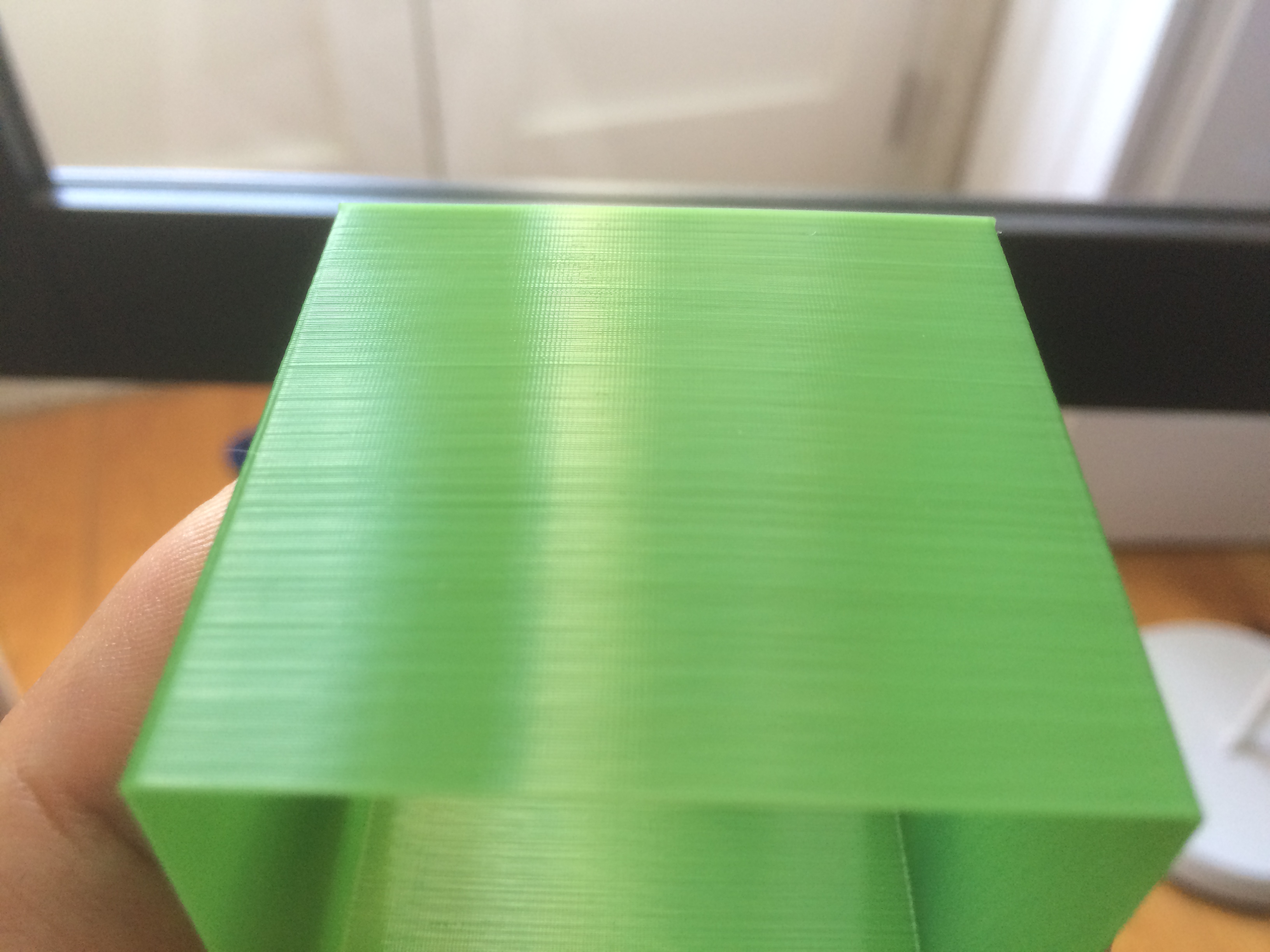
the print quality along the constant-Y side is satisfactory, despite looking bad in this picture. The banding and general inconsistent layer appearance along the constant-X face of the print results in ugly prints though.
fsilva
on 23 Apr 2018
I decided to try a slightly modified cube to test a theory. Unrelated to the theory I was testing, I'm struck by the difference I see when looking at the front side X-axis surface vs the backside x-axis surface.
Here's a shot of the exterior front wall of the cube:
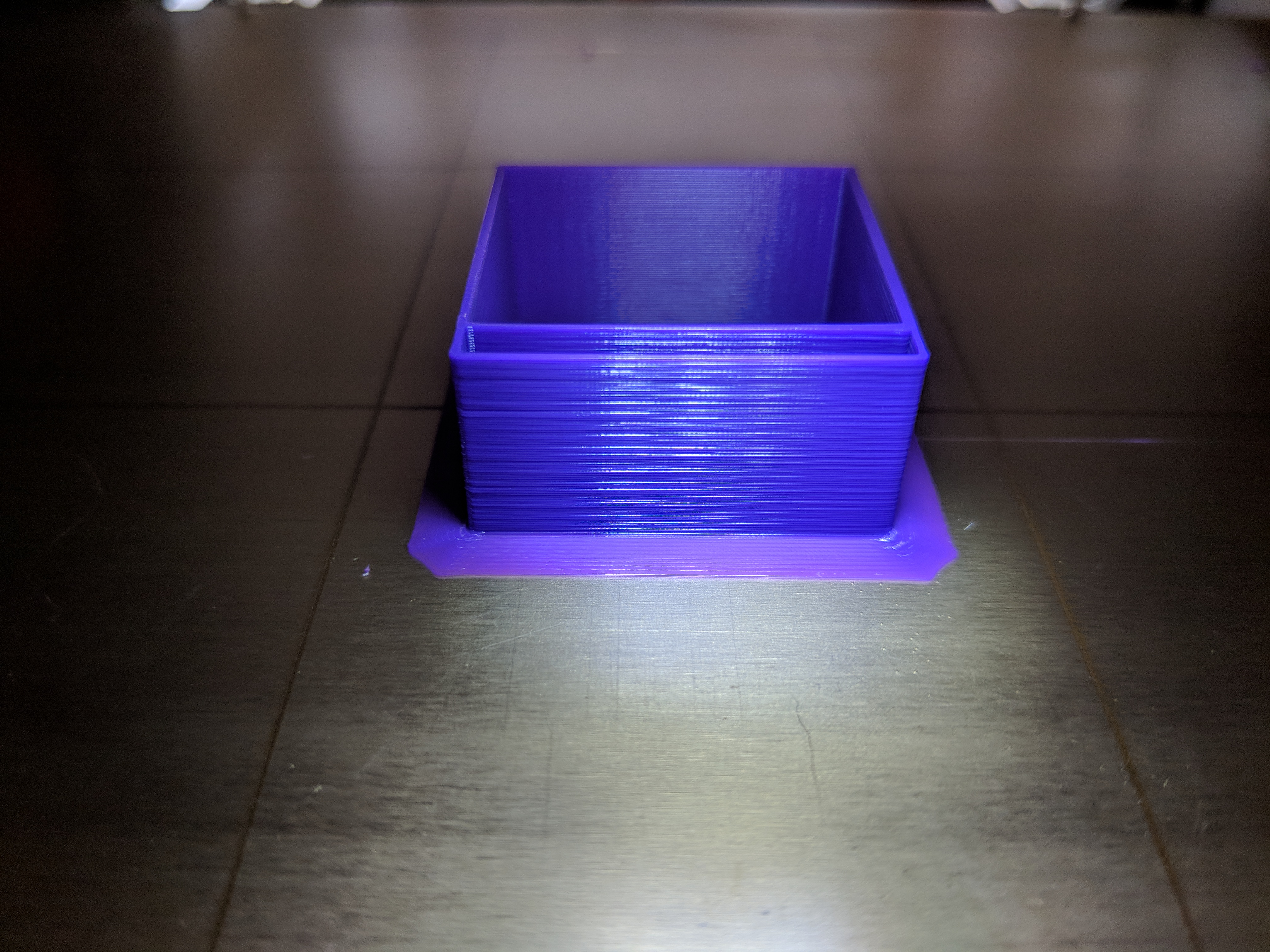
Here's a shot of the interior back wall of the cube. I think it looks a lot like the exterior front.
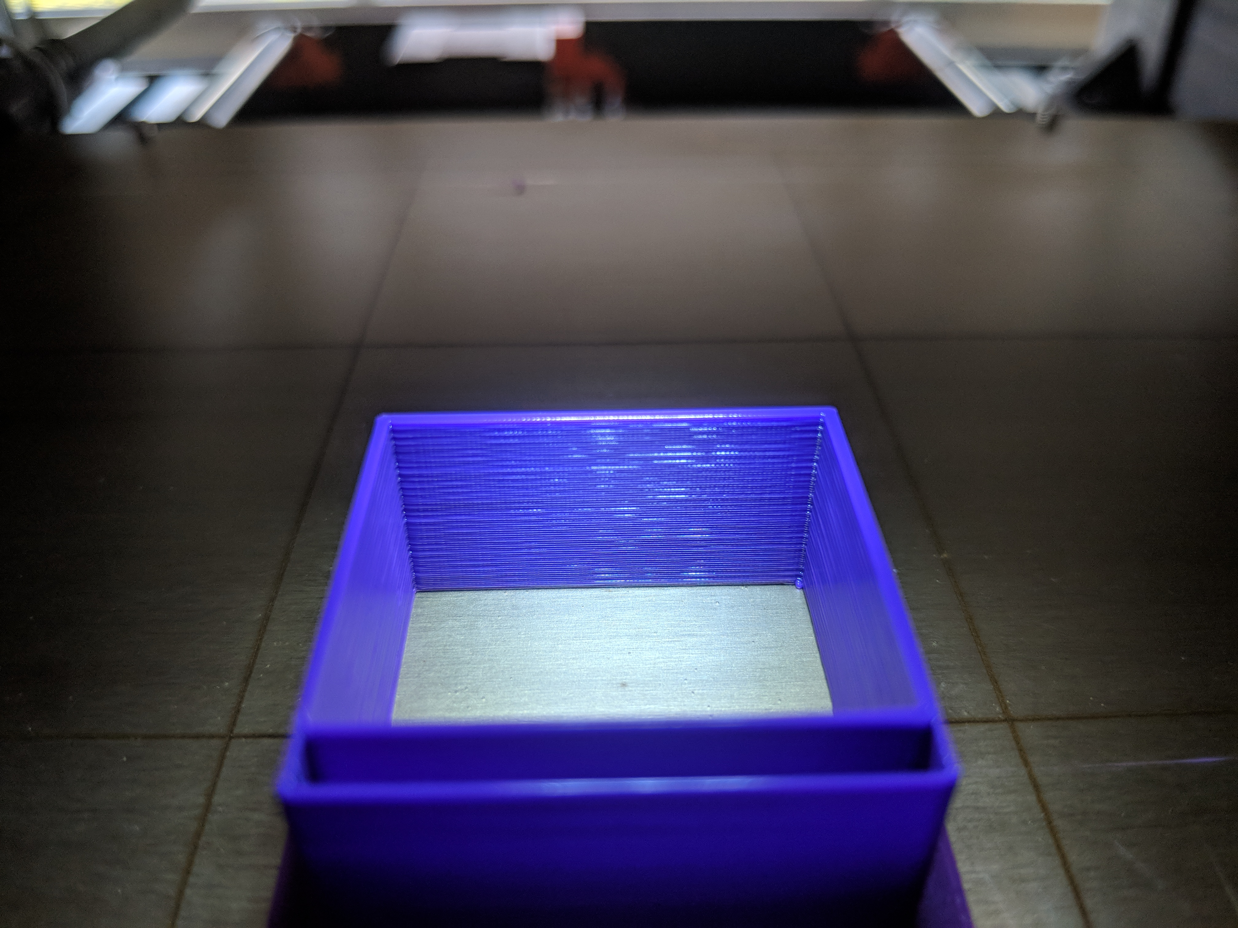
Now, I rotated the cube 180 degrees and took this shot of the exterior back of the cube:
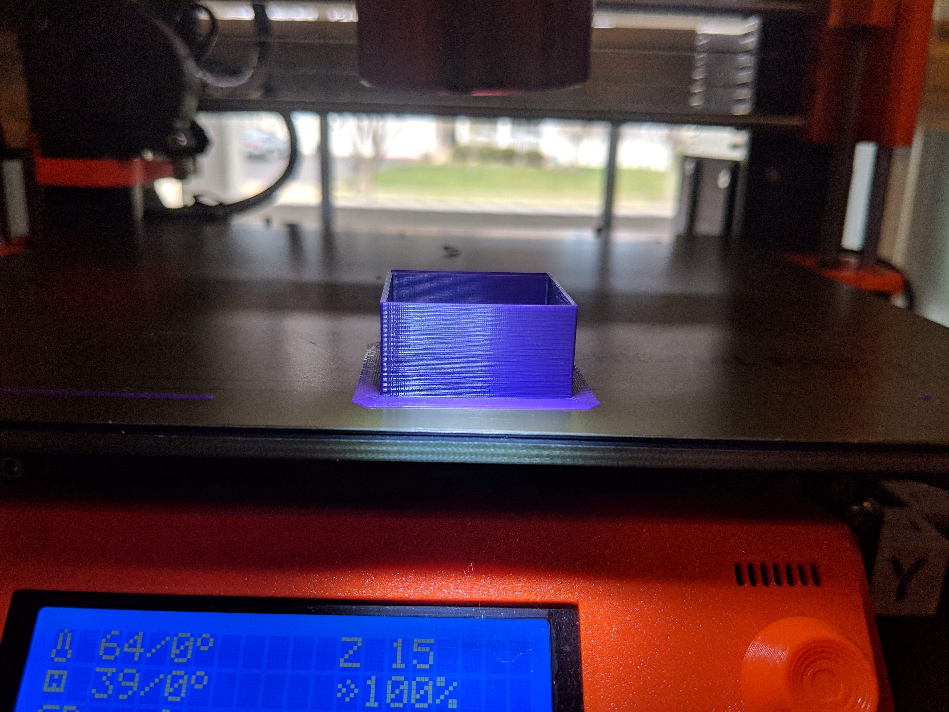
To my eyes this last photo looks quite a bit better than the other two. Maybe it's just an illusion but I thought I'd try and contribute.
rcfsguy
on 23 Apr 2018
@fsilva
Posted this a couple of posts above, i have the same problem.
Y axis is quiet and makes smooth walls, X axis rattles on both machines and produces prints with a pattern.
https://imgur.com/a/CzqAehs
It's not a mechanical problem, considering with how often i disassembled and exchanged parts for the X axis. ( i exchanged it all multiple times.)
devilhunter84
on 23 Apr 2018
@devilhunter84 apologies, missed your post. It's getting difficult to track all the issues with 300 posts.
Does anyone know if the MK2 also has this problem?
fsilva
on 23 Apr 2018
@fsilva
I made a new topic in the forum for this:
https://shop.prusa3d.com/forum/hardware-firmware-and-software-help-f64/x-axis-movement-problem-but-it-does-not-seem-to-be-t15881.html
This is perhaps another extrusion related problem, until we can say for sure lets post over there.
devilhunter84
on 23 Apr 2018
@devilhunter84 Thanks! Unfortunately it seems we have problems in opposite axes! Maybe if we combine both our printers we can build one that does great prints. I´ll move this over to the forum.
fsilva
on 23 Apr 2018
@rcfsguy what happen if you rotate the cube 45 degrees on the bed and print it like that. ?
alfskaar
on 24 Apr 2018
@alfskaar You know... I did that a couple weeks ago but can't remember the result. I will try again after work today.
rcfsguy
on 24 Apr 2018
@ericclinedinst why post screenshots?
GurliGebis
on 24 Apr 2018
There may be multiple effects going on, though it seems we found one culprit, which causes inconsistent extrusion like on the bunny at the very top of this thread. These inconsistent extrusions are caused by the Slic3r's "Slow down if layer print time is below certain time" feature. This slow down triggers for small objects only, therefore large prints should be fine. You may try to set the filament cooling "Slow down if layer print time is below " parameter to a very low number to disable a cooling slow down to see whether it helps with your issues, or you may try to print multiple copies of the same object to eliminate the cooling slow down.
The explanation of the issue is the following: The current slic3r will slow down all the extrusions of a layer but the external perimeters, if the layer prints too shortly, therefore it would not cool down before laying another layer on top of it. The extrusion moves are slowed down proportionally, for example for a 50% slow down, an inner perimeter may be slowed down from 50 to 25mm/sec, while an infill may be slowed down from 170 to 85mm/sec. If slowing down the inner extrusions is not sufficient, Slic3r will slow down the external perimeters as well.
As you can see, Slic3r may slow down the inner perimeters extremely while keeping the speed of external perimeters unchanged. This leads to an extruder pressure deficit, which shows up as gaps at the seams, and inconsistent extrusion starting with the seam. If you just disable the slow down, the inconsistent extrusion will go away, but you may have cooling issues.
We are working on a Slic3r patch release to be released ASAP, where the cooling logic will be redesigned. We are also working on a bigger Slic3r release, which is in an internal alpha stage as of now, so stay tuned. The new cooling logic will not slow down the extrusion moves proportionally, but it will slow down the infill first until it reaches the speed of internal perimeters, then both the infill and the internal perimeters will be slowed down until they reach the speed of external perimeters, then all the extrusions will move at the same velocity and if further slow down is needed, they will be slowed down simultaneously. The new logic is actually smarter than what you will get with Simplify3D, which slows down all moves proportionally in a similar fashion to the old Slic3r.
From the photos you guys posted we also suspect that the Z motor currents may be set a little bit too low for some machines, so we work on that as well, see
https://github.com/prusa3d/Prusa-Firmware/commit/5a9cc39562fdf6804e3dafdc241226c4f2f6fc7a
bubnikv
on 24 Apr 2018
I will try this as soon as I get home. I had tried lowering the e current previously but not raising the z, will try that too with M911/912
c-stewart
on 24 Apr 2018
Does anyone know if the MK2 also has this problem?
In regard to the Slic3r's cooling logic issue, the MK2 shows similar effect, but it is much less pronounced, because the MK2 Slic3r profiles dictate significantly slower extrusion speeds for infill, therefore the layer print times are higher and the slow down kicks in with less vigor.
bubnikv
on 24 Apr 2018
@rcfsguy Is it MK2.5 or MK3? Will the pattern disappear if you print multiple of the cubes? What slicer are you using?
bubnikv
on 24 Apr 2018
@ff8jake https://user-images.githubusercontent.com/8582658/38383035-07ca1e58-38d1-11e8-86e4-aa365c50e951.jpg This is the effect you get from the current Slic3r cooling logic with the very high infill speeds. As of now, we are testing a Slic3r patch release with a new cooling logic.
bubnikv
on 24 Apr 2018
@bubnikv
I found that this slow down logic is not working as it should. For example, if I print with PLA a small cylinder, the slic3r slows down the printing. The result is that the hot end is moving really slow over the part for more time not allowing it to cool.
It would be better if the hot-end printed the layer keeping the speed and then moved a little away to let the layer cool. Then continue with the next layer.
Panayiotis-git
on 24 Apr 2018
@bubnikv My samples were printed on an MK3. I used S3D as the slicer. I will try a multiple cube print tonight and post the results when complete.
rcfsguy
on 24 Apr 2018
@bubnikv I know you're getting hit with a torrent of questions, but any explanations on the Z current increase (i.e., what do you guys think it will fix)?
TheBrigandier
on 24 Apr 2018
@ff8jake Each part is made with some manufacturing tolerances. The Z motors have a variance in coil resistance, the lead screws may be a bit tight etc. If the component tolerances align badly, the old current settings may not be powerful enough to lift the X axis reliably. The new current value is similar to what we used on the MK2, which is known to work reliably.
bubnikv
on 24 Apr 2018
@bubnikv Awesome, thanks for the info. Will compile it up when I get home and post some pics.
TheBrigandier
on 24 Apr 2018
I hope we are on the same page, that there are various effects being reported in this thread. Surely some of the issues reported here may be caused by some manufacturing, component tolerances or firmware problems. However, there are newcomers to 3D printing reading this thread, who may expect a bit too much of the FDM technology. I would like to point out, that
1) Some of the filaments produce a sightly inconsistent extrusion. Namely, the mineral (talc, lime) filled filaments like these often do not print quite nicely as filaments without mineral fillers:
https://user-images.githubusercontent.com/8582658/38393118-6eda9c8a-38ef-11e8-934f-9be3f02ef9b9.jpg
https://user-images.githubusercontent.com/8582658/38458046-7b61102c-3a5e-11e8-8cff-a8139498030b.jpg
2) As @Sebastianv650 has shown under his microscope, there is always some irregularity in the extrusion. Only some filaments show this irregularity more than the others.
bubnikv
on 24 Apr 2018
@bubnikv what is your take on the motor driver VREF pot trim solving very similar issues in the soliforum links above? Is this related to the current increase you mentioned for z?
Also thank you for your open communication. Very much appreciated.
nstis
on 24 Apr 2018
what is your take on the motor driver VREF pot trim solving very similar
issues in the soliforum links above? Is this related to the current
increase you mentioned for z?
Could you be more specific, please?
On Tue, Apr 24, 2018 at 9:19 PM, ensitmike notifications@github.com wrote:
@bubnikv https://github.com/bubnikv what is your take on the motor
driver VREF pot trim solving very similar issues in the soliforum links
above? Is this related to the current increase you mentioned for z?—
You are receiving this because you were mentioned.
Reply to this email directly, view it on GitHub
https://github.com/prusa3d/Prusa-Firmware/issues/602#issuecomment-384048924,
or mute the thread
https://github.com/notifications/unsubscribe-auth/AFj5IyjnJ9TEIiqYuvA_c13JTMvqBdNHks5tr3qugaJpZM4TI5uR
.
bubnikv
on 25 Apr 2018
@bubnikv
http://www.soliforum.com/topic/10108/ex
http://www.soliforum.com/topic/4759/new
http://www.soliforum.com/topic/9347/sol
nstis
on 25 Apr 2018
@ensitmike wow they are showing the EXACT same issues we are all seeing!!!
jonbet83
on 25 Apr 2018
@jonbet83 I wasn't sure if I was being too persistent, but I thought these got looked over and wanted to help out and make sure they were seen. If they aren't relevant that is alright, but I'm glad you agree. I think they look very similar as well.
nstis
on 25 Apr 2018
@ensitmike It seems very relevant by way of the patterns and issues are identical. The drivers are different I know but it seems like good very relevant information.
I see what @bubnikv was saying about the slicer slowdown issues was correct, I tried that out by printing several of the same rabbits but these issues (based on the pictures at the start of this issue) are still no further forward than the day when @ff8jake opened it. These aren't user or filament issues not all of these people, you can see evidence of it all over twitter, facebook and forum. And its more than likely someone, somewhere as already found and fixed the same problem with a different board or printer
jonbet83
on 25 Apr 2018
@ensitmike You can experiment with the current settings of your stepper motors with the M911 G-code.
The currently released MK3 firmware has the currents set to
M911 X16 Y20 Z28 E36
The upcoming MK3 firmware relase will have the Z current set higher, and E current set lower. You may try those.
M911 X16 Y20 Z35 E26
bubnikv
on 25 Apr 2018
I'm surprised nobody has tested the current settings yet and reported back.
vertigo235
on 25 Apr 2018
I did try the new settings, z up and e down, it did not help with my
situation unfortunately. I'm at work right now it I'd upload a picture.
Will do later today.
On Wed, Apr 25, 2018, 10:45 AM Josh Jones, notifications@github.com wrote:
I'm surprised nobody has tested the current settings yet and reported back.
—
You are receiving this because you were mentioned.
Reply to this email directly, view it on GitHub
https://github.com/prusa3d/Prusa-Firmware/issues/602#issuecomment-384313330,
or mute the thread
https://github.com/notifications/unsubscribe-auth/AJutFZSnDDpKsl3dAvPAMkzEFY6lCtt_ks5tsIwGgaJpZM4TI5uR
.
c-stewart
on 25 Apr 2018
It sure seems to be related to poor management of the micro stepping, maybe some motors are better at tolerating it than others.
vertigo235
on 25 Apr 2018
So the potentiometer settings are managed within the firmware with the TMC2130, I was skimming this expansive write up on the TMC2130 drivers.
https://toms3d.org/2017/12/09/tmc2130-guide/
I guess the question is how do you tune that? This may have already been discussed here in the thread.
vertigo235
on 25 Apr 2018
@vertigo235 The TMC drivers have an analog input pin that a potentiometer can be hooked up to. Attaching one has the benefit of offering greater flexibility, but yes in theory you can control current through software as bubnik stated. Potentiometers have unique impedance characteristics though, so I'm looking into data sheets now. You can find more info in the TMC data sheet.
When a high flexibility of the output current scaling is desired, the analog input of the driver can be enabled for current control, rather than choosing a different set of sense resistors or scaling down the run current via IRUN parameter. This way, a simple voltage divider can be used for the adaptation of a board to different motors.
nstis
on 25 Apr 2018
Lulzbot's new Printer, the Lulzbot mini 2 uses the Einsy Retro. (Einsy with Endstop switches and 12V fans)
I found lulzbot's source code for their Marlin implementation and all TMC2130 driver code here:
https://code.alephobjects.com/search/query/e4Ud8hQeHutW/#R
So far i have found no linear corrections or sine wave corrections on their code, but from the looks of it, they do things the more static way, in terms of raw numbers instead of algorithm corrections.
https://code.alephobjects.com/diffusion/MARLIN/browse/devel/Marlin/
Still digging through this, but i'm not a software guy.
@bubnikv @XPila
might peek at their homework a bit?
Of course, that would require assuming something could be done better about the power management and microstepping implementation of the TMC's, after all.
devilhunter84
on 25 Apr 2018
I tried M911 X16 Y20 Z35 E26 on a calibration cube and am currently printing a lithophane with it in my starting g-code. The resulting calibration cube still had a moiré effect though it did seem to change frequency if that makes sense. I had to rush out of the house and didn't take a photo.
mvasilakis
on 25 Apr 2018
@mvasilakis
Gcode is not my strong suite. Would it be possible to do a "temperature tower" that is programed to run through different current settings for the motors rather than temperature?
nstis
on 26 Apr 2018
Should be possible. Insert a M910; M911 Xn Yn Zn En; M912 Xn Yn Zn En;
every so many layers at the layer changes
On Wed, Apr 25, 2018, 6:18 PM ensitmike, notifications@github.com wrote:
@mvasilakis https://github.com/mvasilakis
Gcode is not my strong suite. Would it be possible to do a "temperature
tower" that is programed to run through different current settings for the
motors rather than temperature?—
You are receiving this because you were mentioned.
Reply to this email directly, view it on GitHub
https://github.com/prusa3d/Prusa-Firmware/issues/602#issuecomment-384451703,
or mute the thread
https://github.com/notifications/unsubscribe-auth/AJutFe-Itm-RpZiMdmycl3f2pX5Mdz7hks5tsPYlgaJpZM4TI5uR
.
c-stewart
on 26 Apr 2018
@ensitmike you can use the above command M911 E
values. If you put in the Slic3r layer change, you can later do a search
and replace that number at different layers for the ones you want, so
different heights will be printed with different extruder currents.
On Thu, Apr 26, 2018 at 12:18 AM, ensitmike notifications@github.com
wrote:
@mvasilakis https://github.com/mvasilakis
Gcode is not my strong suite. Would it be possible to do a "temperature
tower" that is programed to run through different current settings for the
motors rather than temperature?—
You are receiving this because you were mentioned.
Reply to this email directly, view it on GitHub
https://github.com/prusa3d/Prusa-Firmware/issues/602#issuecomment-384451703,
or mute the thread
https://github.com/notifications/unsubscribe-auth/AAccyJ1KPCyYmRXnxnKNb1qdAYVhWecmks5tsPYkgaJpZM4TI5uR
.
misan
on 26 Apr 2018
@ensitmike
Absolutely. It could just be added to the layer change gcode.
Just change the z== number to the corresponding layer on the model.
{if layer_z==1}M911 X16 Y20 Z28 E36{endif}
{if layer_z==15}M911 X16 Y20 Z30 E34{endif}
{if layer_z==30}M911 X16 Y20 Z32 E31{endif}
{if layer_z==45}M911 X16 Y20 Z33 E28{endif}
{if layer_z==60}M911 X16 Y20 Z35 E26{endif}
mvasilakis
on 26 Apr 2018
Do you have to do a M910 first before those?
c-stewart
on 26 Apr 2018
Compiled the latest (had to comment out the recent filament unload timer stuff to get it to compile), no changes on my side. Tried a couple prints with M910 + various current settings, no changes.
TheBrigandier
on 26 Apr 2018
Yeah I tried it too before it was updated to RC2 and there was no change to anything print quality wise. only thing I noticed was E cooler Z warmer but that was expected.
@ensitmike did you try the progressing current changes?
jonbet83
on 26 Apr 2018
Are the current setting changes quality issue related? I understand it is more to solve problems with overheating extruder - and to bring the current to the MK2 level, where it is obviously all good. So I did not expect any changes for print quality. (I hope it will not get worse though;-))
stahlfabrik
on 26 Apr 2018
That is my output printing four single-walled cubes at once. If I look the wall it looks perfect, if I play with the light you can see some artifacts
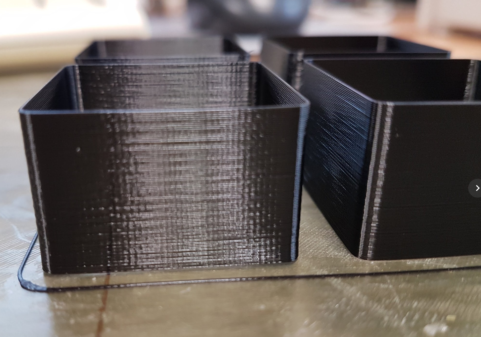
(printed with 3.1.3-245 stock values).
misan
on 26 Apr 2018
I wasn’t sure if they were slightly to do with print quality, z currents, something was mentioned I think that some mechanical components could be tight causing lost steps. But your right, I think I was just hopefull lol
I saw a nice little budda someone printed on mk2s so I had a go at it with the new firmware it’s no we’re near as good. Clear signs of the inconsistency and it’s not cooling slow down causing it as the seam was set to rear and it’s at the front, it’s just making the printer a waste of time using it unfortunately.
jonbet83
on 26 Apr 2018
About the slight improvement with the heat-bed off, it could be a current issue. Every time the bed blinks, the current to the stepper drops a little. Resulting in slight under extruded moments (random).
 alientek
on 26 Apr 2018
alientek
on 26 Apr 2018
@alientek Is this happening for users who have replaced them with a Meanwell supply? I didn't see any mention in this thread but I didn't check the forum.
TheDuggem
on 26 Apr 2018
@TheDuggem I have no clue, it was a shot in the dark. It might not be the PSU but the board itself being a bottleneck for the current.
alientek
on 26 Apr 2018
@TheDuggem I've had the same thought for a while now.
Something about the pattern reminds me of a sine wave. If it was power related I would think the wave pattern would increase & decrease frequency as power is fluctuated. That's not happening. It's a constant and consistent pattern. Related to electronics? Quite possible. Power fluctuation related? IMHO no. I've been tempted to throw a ferrite choke on the extruder assembly wire bundle but honestly I don't think it's extraneous electromagnetic interference so I never bothered.
mvasilakis
on 26 Apr 2018
The Meanwell psu does not fix the inconsistent extrusion. At least one that has been done still prints exacly the same. Note that it still is wired the same and could be causing the same voltage drop at the stepper.
Get Outlook for Androidhttps://aka.ms/ghei36
From: mvasilakis notifications@github.com
Sent: Thursday, April 26, 2018 9:50:54 AM
To: prusa3d/Prusa-Firmware
Cc: Skiidlive; Mention
Subject: Re: [prusa3d/Prusa-Firmware] Inconsistent Extrusion (#602)
@TheDuggemhttps://github.com/TheDuggem I've had the same thought for a while now.
Something about the pattern reminds me of a sine wave. If it was power related I would think the wave pattern would increase & decrease frequency as power is fluctuated. That's not happening. It's a constant and consistent pattern. Related to electronics? Quite possible. Power fluctuation related? IMHO no. I've been tempted to throw a ferrite choke on the extruder assembly wire bundle but honestly I don't think it's extraneous electromagnetic interference so I never bothered.
—
You are receiving this because you were mentioned.
Reply to this email directly, view it on GitHubhttps://github.com/prusa3d/Prusa-Firmware/issues/602#issuecomment-384647970, or mute the threadhttps://github.com/notifications/unsubscribe-auth/Akhg6xEptHVpfXoqVqshzkAkYMgkUae4ks5tsdC-gaJpZM4TI5uR.
Skiidlive
on 26 Apr 2018
I thought about the PSU before too, but I assume the 2.5 has a different PSU, and @devilhunter84 likely has a different PSU since he is using different hardware on his custom build. He mentioned he had a higher rated PSU.
vertigo235
on 26 Apr 2018
Right was printed on mk2, left mk3, using the same mk2 gcode file by prusa but tweaked for the mk3 (left) with 95% flow via addition of "M221 S95" like Slic3r PE MK3 does.
If I still had some of the gold left I would have used it to keep the filament variable constant but I don't think the observed differences can be blamed on that given the noticed print surface quality difference seems to apply to all (of at least my) mk3 prints regardless of material.
I've rebuilt this mk3 a few times now, even printed some replacement parts. No change.

If it weren't for the significant downgrade in print surface quality vs my experience with the mk2, I'd be really pleased with this mk3.
MTJC
on 27 Apr 2018
@MTJC I will trade you an MK3 for that MK2. It even has Misumi bearings. :)
TheBrigandier
on 27 Apr 2018
@ff8jake lol.
Unfortunately I couldn't even if I wanted to. I foolishly sold it before receiving my Mk3. It had Misumi bearings in it too, as does my now current Mk3.
MTJC
on 27 Apr 2018
So am I to understand, after so much deliberation, that we might be down to driver settings for the steppers, or other such software algorithm issues? should we all be trying “temp tower” like combinations of different current settings in our gcode since we don’t have access to potentiomiters? If anyone has a gcode they would like others to run for confirmation please post it
 Dioblieum
on 27 Apr 2018
Dioblieum
on 27 Apr 2018
We have a Slic3r release with the new cooling slow down logic to fix the
initial issue reported here.
https://github.com/prusa3d/Slic3r/releases/tag/version_1.39.2-beta
Please update the printer presets bundled with the release by running the
Wizard from the Help menu.
On Fri, Apr 27, 2018 at 7:44 PM, Dioblieum notifications@github.com wrote:
So am I to understand, after so much deliberation, that we might be down
to driver settings for the steppers, or other such software algorithm
issues? should we all be trying “temp tower” like combinations of different
current settings in our gcode since we don’t have access to potentiomiters?
If anyone has a gcode they would like others to run for confirmation please
post it—
You are receiving this because you were mentioned.
Reply to this email directly, view it on GitHub
https://github.com/prusa3d/Prusa-Firmware/issues/602#issuecomment-385043605,
or mute the thread
https://github.com/notifications/unsubscribe-auth/AFj5IxQBVwM8iRdqUVkJ3OKoLBYYZF14ks5ts1kCgaJpZM4TI5uR
.
bubnikv
on 27 Apr 2018
I’ll give that a go later with my little bunny model But that’s really not going to sort out this extrusion issues as it’s not slic3r specific
jonbet83
on 27 Apr 2018
Fascinating. You really think original issue was caused by cooling. In FB group there was a nice experiment, lots of MatterHackers' Mascot Phils were printed, almost hundred of different mk3 with different filament. Every single Mk3 has the same issues described in this ticket and it's not related to cooling logic.
sneaky-tricky
on 27 Apr 2018
@sneaky-tricky link?
TheBrigandier
on 27 Apr 2018
https://www.facebook.com/groups/Prusai3users/?ref=bookmarks
I would be reluctant to say that all the results were garbage though. Certainly not like what has been posted here in this issue or on the prusa forums regarding this issue too.
Search for "sauce" in that group and you'll see the test prints that @sneaky-tricky is talking about.
vertigo235
on 27 Apr 2018
sneaky-tricky
on 27 Apr 2018
The Slic3r update should solve the issues shown at the 4th and 5th picture from the very first post in this thread.
bubnikv
on 27 Apr 2018
Thanks. 4th, 5th picture, I can agree with this.
sneaky-tricky
on 27 Apr 2018
@bubnikv Is there any insight from the prusa devs regarding the correlation with potentiometer adjustments on older style drivers that fixed similar problems? How can this be adjusted with the TMC2130 drivers for possibly calibrating out the effects folks are seeing?
vertigo235
on 27 Apr 2018
Not sure why anyone thought that would solve the problem since the slow-down was dependent upon short layer times and it never mattered how large my print. Thanks for testing it, I won't bother.
Skiidlive
on 27 Apr 2018
@ericclinedinst Can you confirm that this issue disappears as soon as you remove the mk2.5 upgrade?
CacikeOtoao
on 27 Apr 2018
Has anyone attempted to run the mk2 extruder assembly on their mk2.5/mk3 and see if the issue is present? Or viceversa, running mk2.5/mk3 extruder assembly with mk2 firmware? I guess you could just alter esteps and cover the filament sensor.
CacikeOtoao
on 27 Apr 2018
What cooling fix? Did I miss something?
stahlfabrik
on 27 Apr 2018
@stahlfabrik A slic3r issue with speeds on small areas, nothing to fix the inconsistent extrusion that this the subject of this thread, but may have contributed to some of the issues in photos shared, the bunny photo was specifically referenced.
vertigo235
on 27 Apr 2018
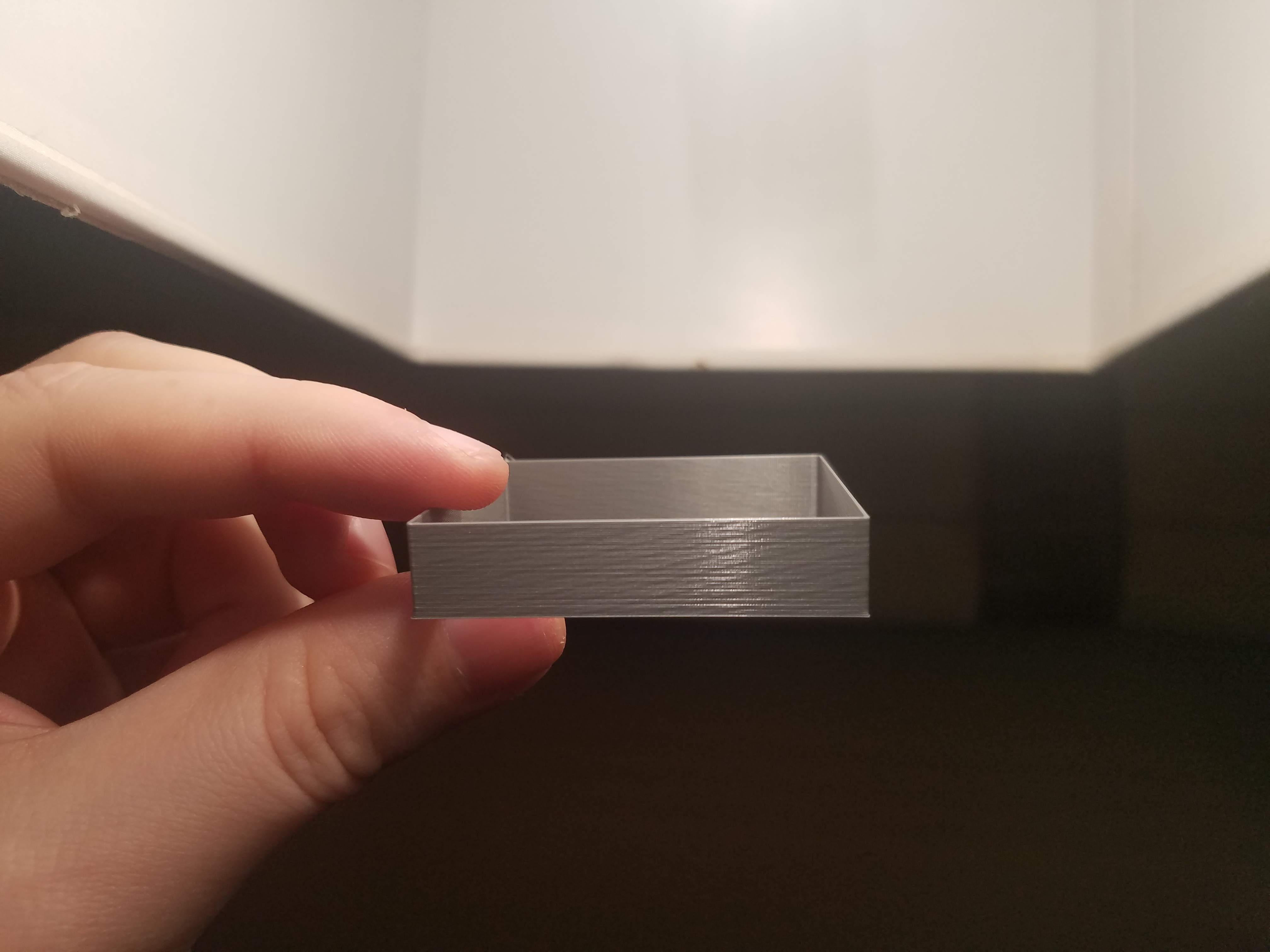
This is with the beta Slic3r release. Tried a couple and didn't see much change, but this particular print is interesting. jltx on the forums was curious about this in the printer start gcode:
M221 S{if layer_height<0.075}100{else}95{endif}
I didn't see him post any results yet, so I decided to try something. If you guys recall when the MK3 first came out, there was a 5% overextrusion issue that Prusa fixed by adding the above. jltx was speculating maybe this on the fly flow correction could be causing some floating point accuracy errors. To eliminate this factor, I removed the line from my start gcode and adjusted my E-steps from 280 to 266 (95%).
The pic still shows the issue, but it was harder for me to get that just right angle to make it appear. Also it seems like the moire effect has become more pronounced. In person, I want to say this print looks more uniform except for the moire.
Anyone else want to try some tests without this line and see the results? I am shooting in the dark here obviously, but it's been pretty rare we find anything that causes changes to this artifact.
TheBrigandier
on 27 Apr 2018
@ericclinedinst
Is that white PLA/PETG?
Could you perhaps print the same thing again with a different color?
I have problems printing with white PLA or white PETG on the MK2s, too.
https://shop.prusa3d.com/forum/how-do-i-print-this-printing-help--f79/help-getting-rid-of-z-banding-visible-horizontal-l-t4069.html#p38175
https://www.reddit.com/r/3Dprinting/comments/3psr19/is_white_pla_harder_to_makeprint_with/
White PLA is notoriously hard to print with, because of it's Titanium dioxide additive, it's goopy nature and because manufacturers cannot get a decent 1.75mm diameter onto it. Most white PLA spools from different manufacturers i've measured went from 1.65 to 1.85, that's quite more than the 0.05 tolerance that they write on their websites.
Yes, i saw this pic here from you https://user-images.githubusercontent.com/38290346/38624353-cad4c2ea-3d9f-11e8-9e21-a2017fe939eb.jpg
What i mean is i had three rolls of white PLA from dasfilament, 1 spool printed normal, while the other two printed like utter crap. If you could find the time to make a single wall 20mm cube on the 4 printers you have that could be useful here. Perhaps off-white color though, like PLA natural or beige. (these tend to print the best.
Silver shows absolutely any flaws possible, and well, white is problematic by nature.
@ff8jake
I asked this question a bit further up
bubnikv answered it.
I tried it without this line, but it did not get better (without this line, we are overextruding by 5%)
devilhunter84
on 27 Apr 2018
@devilhunter84 Yeah I am aware, that's why I adjusted steps down 5% to compensate. Will check the comments above.
TheBrigandier
on 28 Apr 2018
Damn, that IS a horrible print quality.
Thanks for checking. Now we can surely omit Filament problems here, too.
devilhunter84
on 28 Apr 2018
Having issues still with latest Slicer beta.
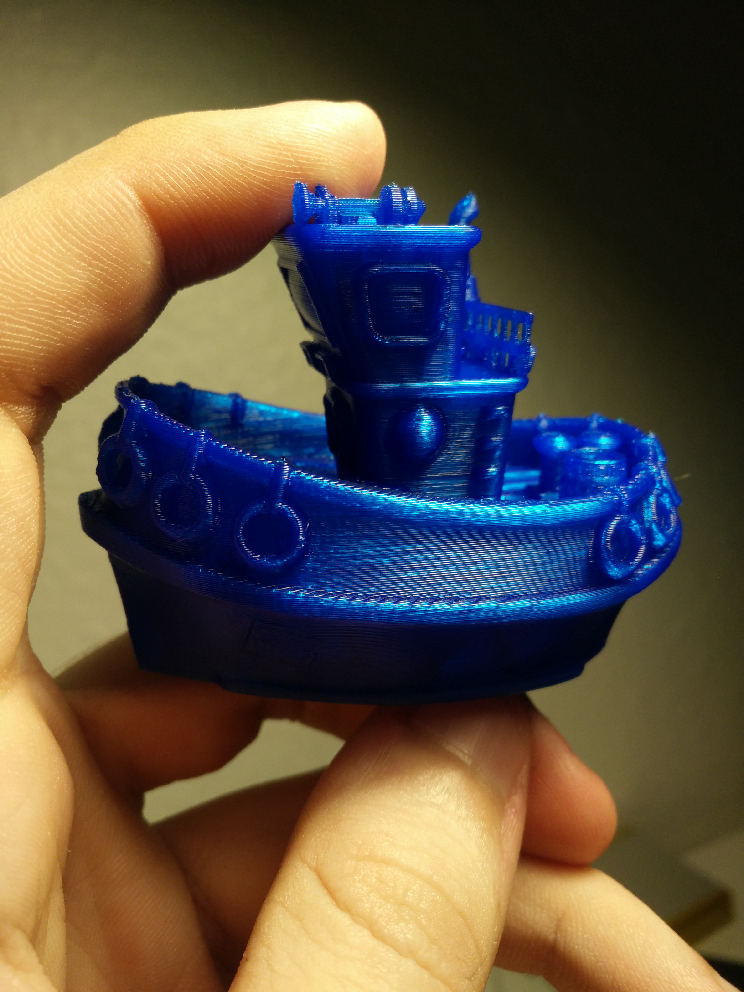
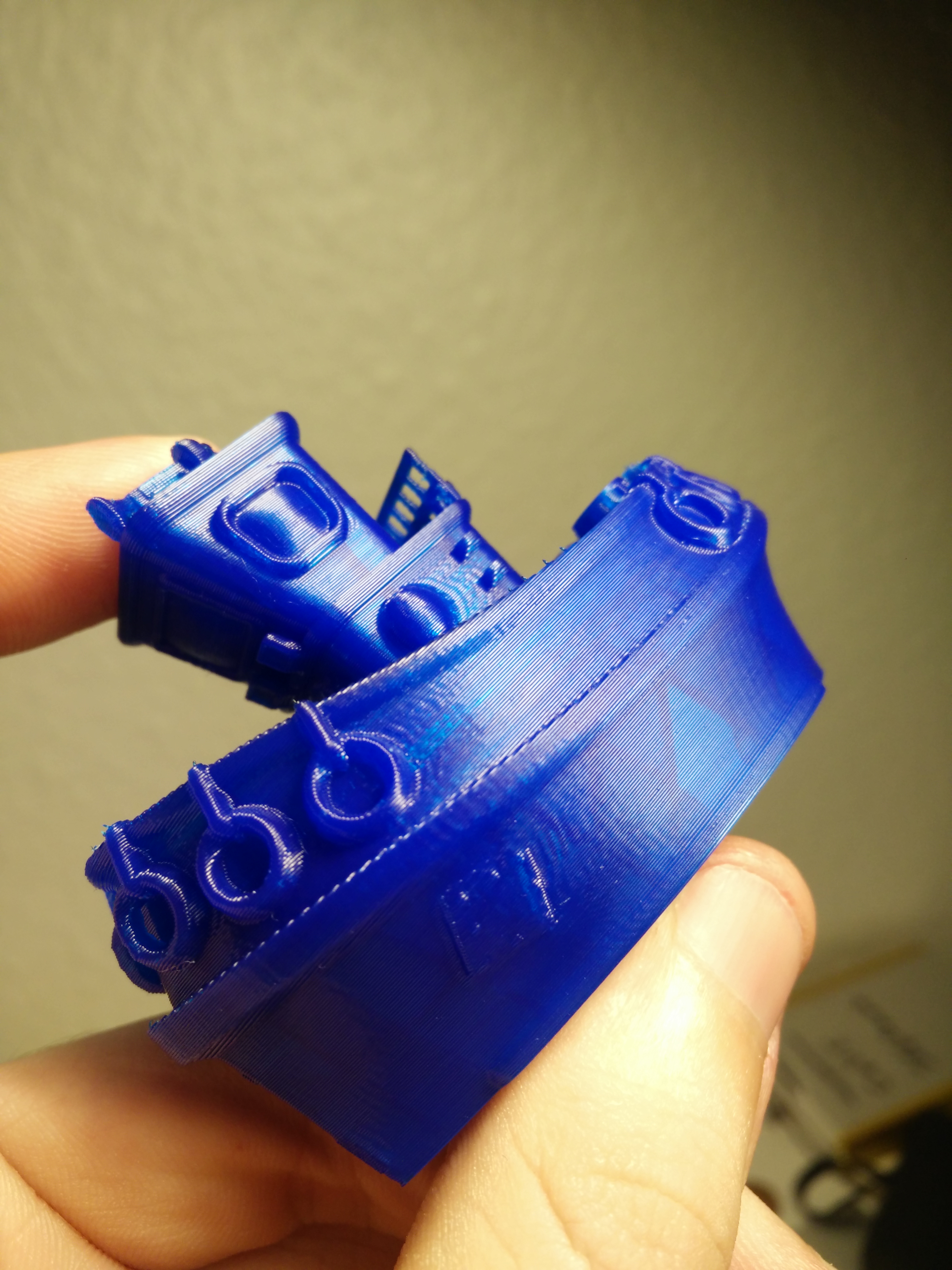
alientek
on 28 Apr 2018
Here's my results. I sliced with S3D 4.0.0 and printed single wall. This is Inland gray PLA at 215C. Extrusion multiplier in S3D was set to 98%. Extrusion width was set to 0.40mm. This is a 3.2.0-RC2 firmware build.
15mm/s:
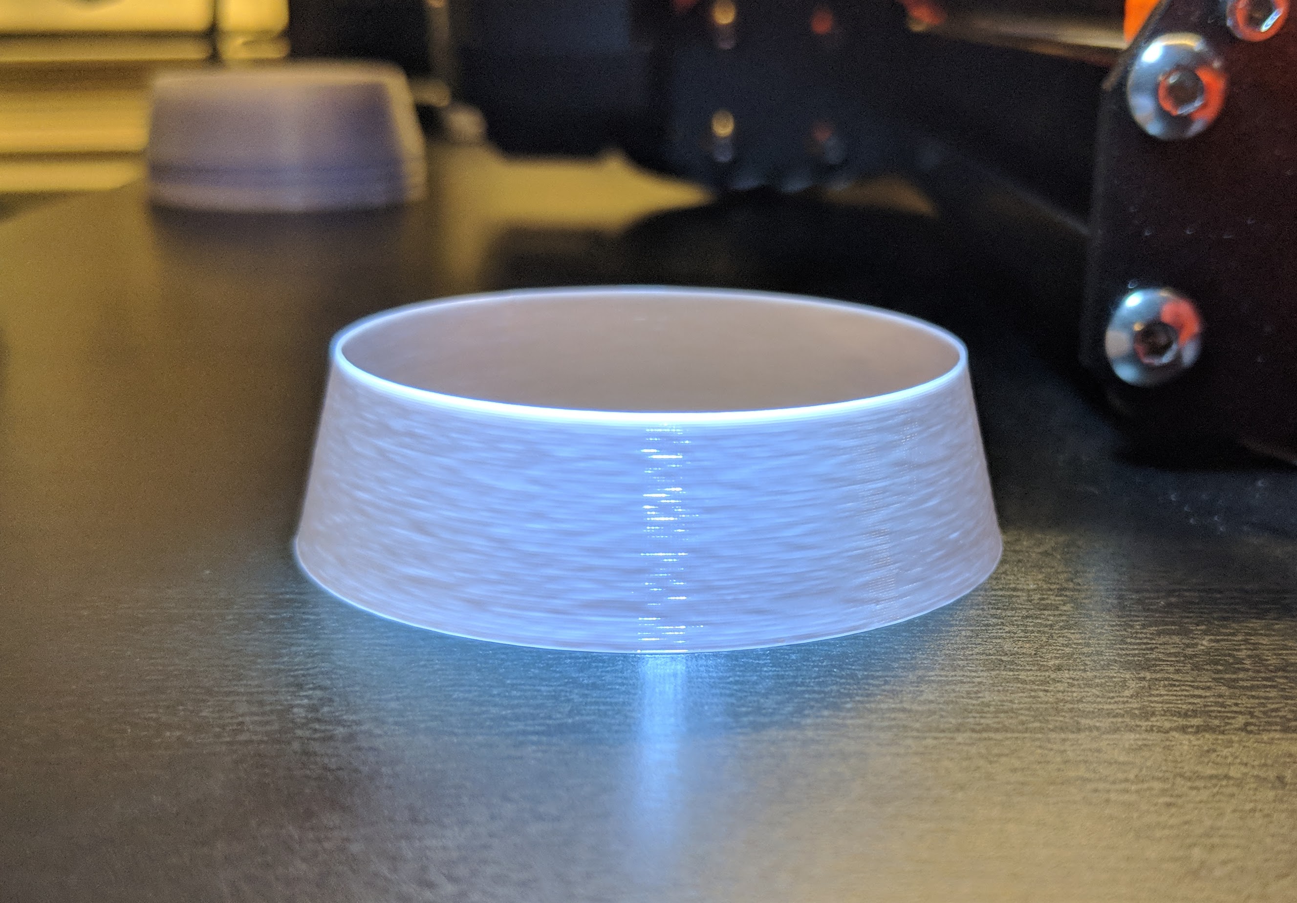
26mm/s:
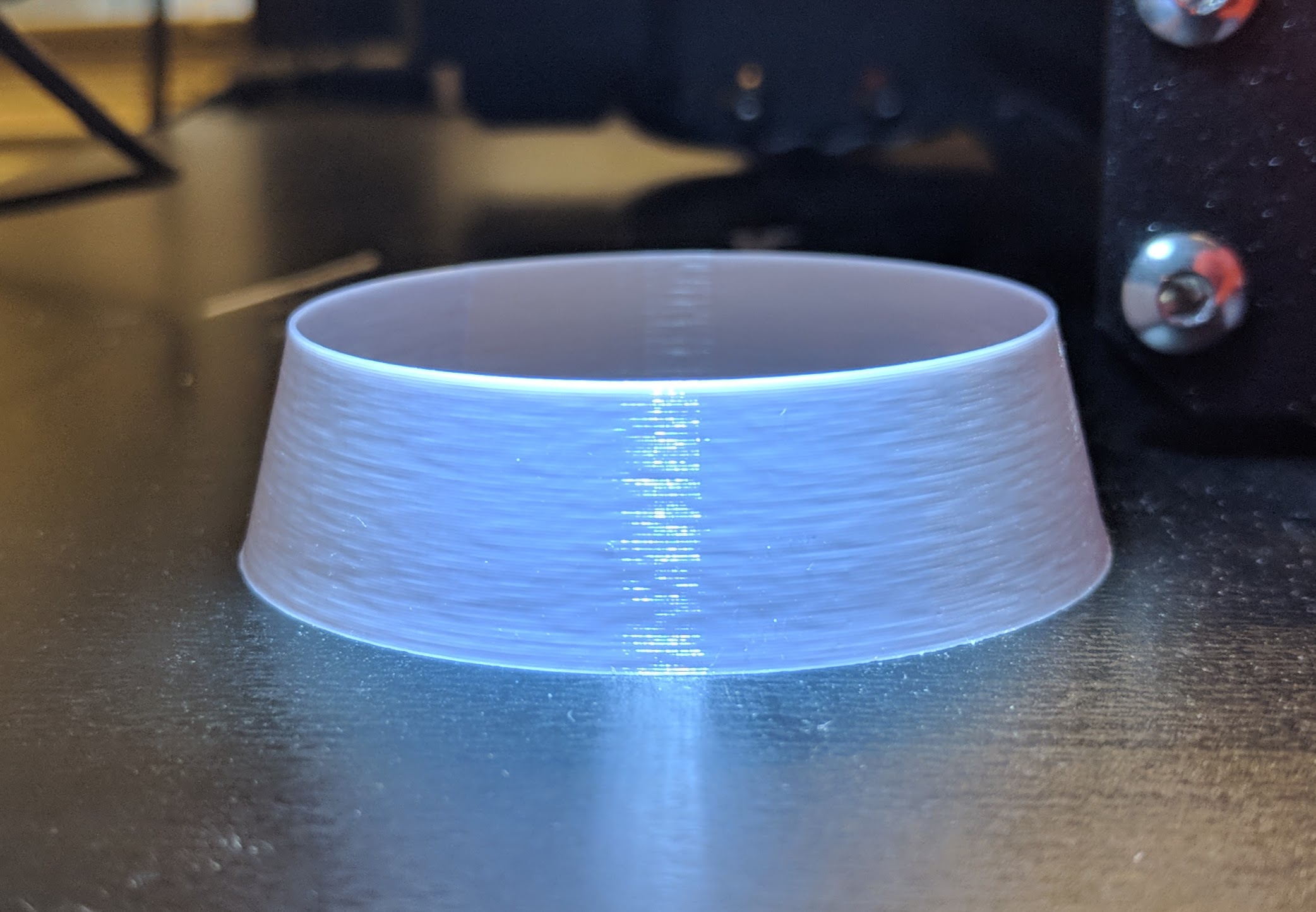
50mm/s:
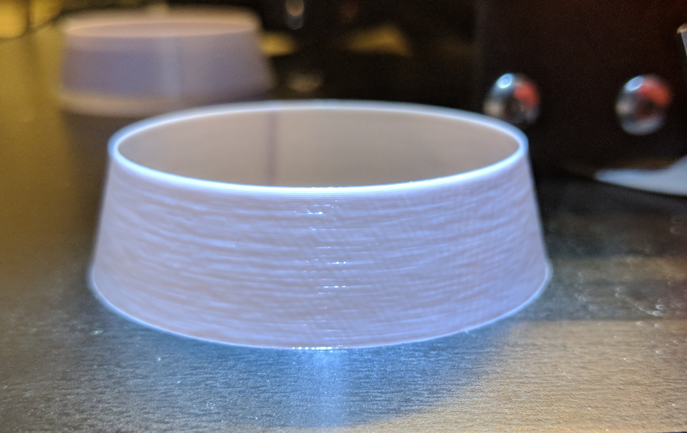
70mm/s:
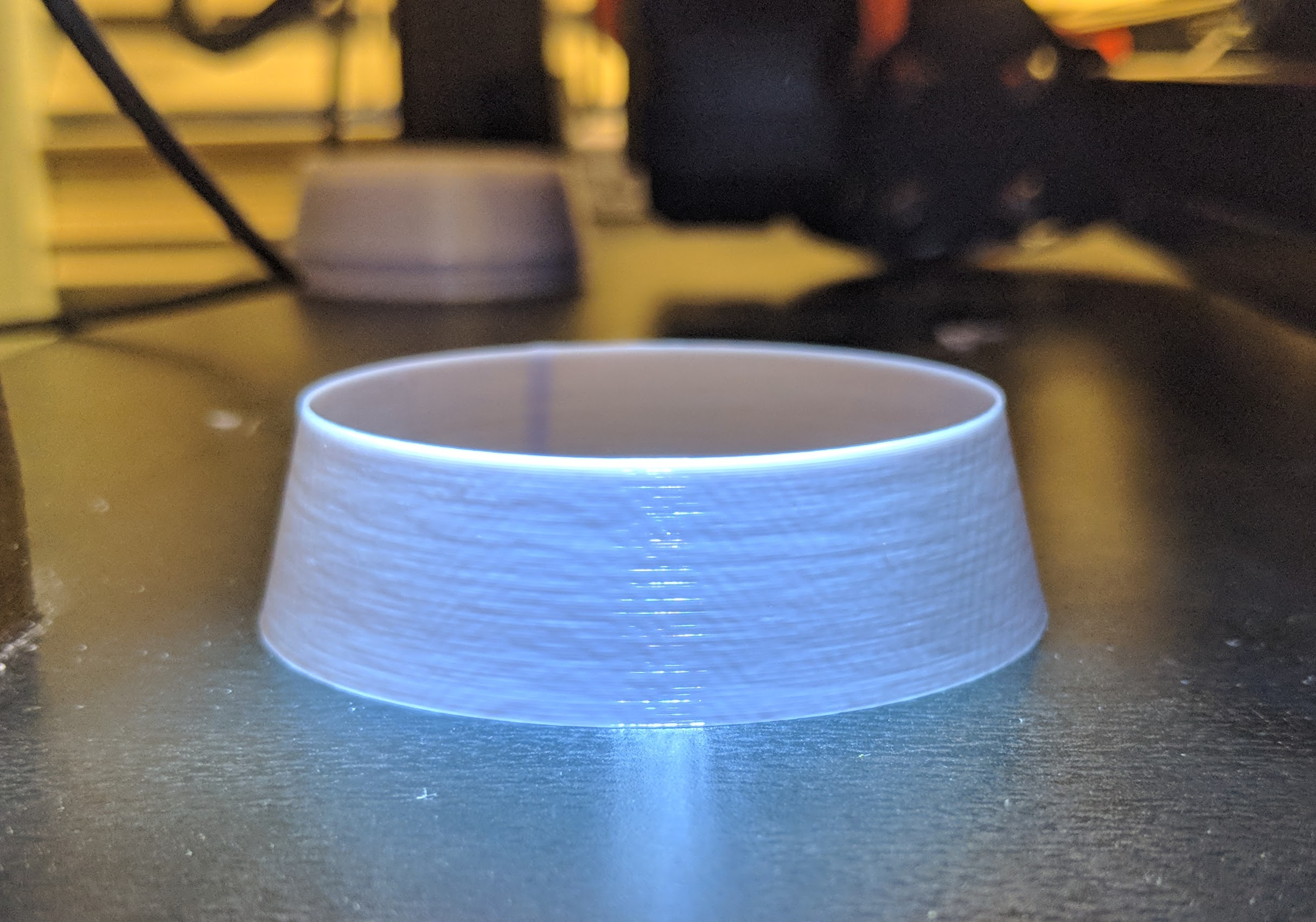
This is 50mm/s with a _100%_ extrusion multiplier:
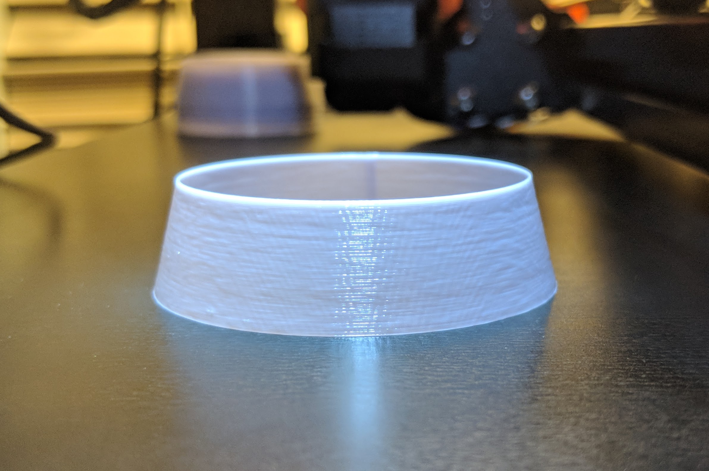
This is 50mm/s with a _102%_ extrusion multiplier:
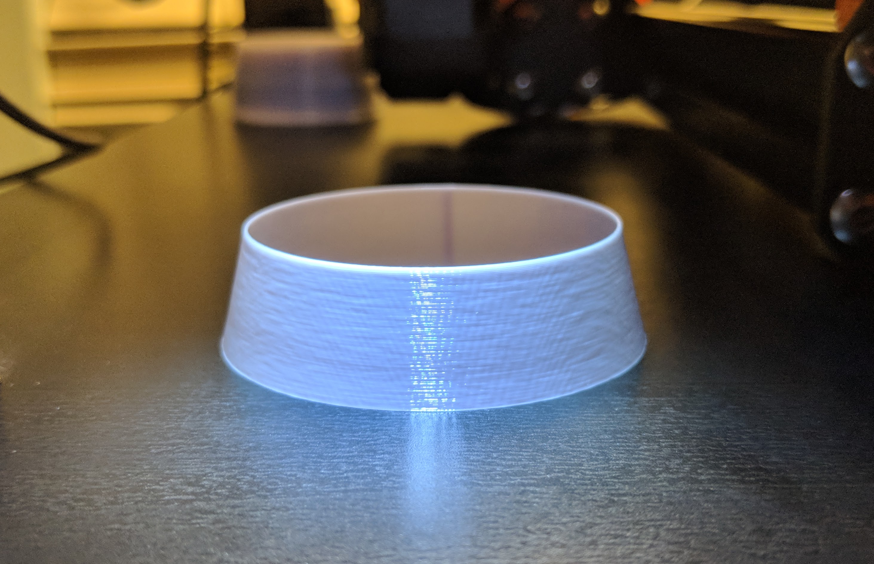
These prints look nearly flawless to the naked eye.
Finally, here's PETG (sorry it was either black or translucent orange) and I could not adjust the light angle in a way that showed any flaws. As far as I'm concerned this print is pristine.
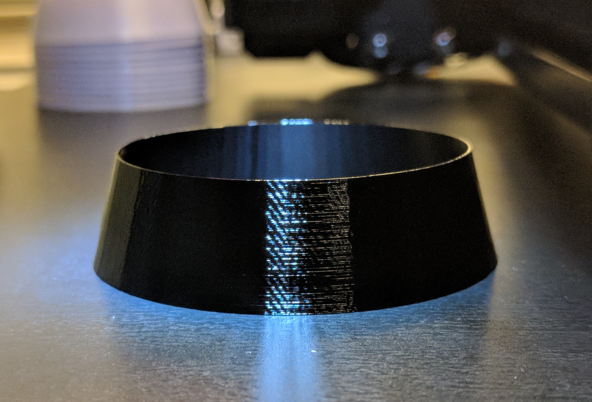
rcfsguy
on 28 Apr 2018
I wonder if Prusa has the ability to solder up a potentiometer to AIN_IREF and test the output.

I am curious if the analog signal is maintained to output or if it is converted to digital. The data sheet states greater "flexibility" of current control when using IREF, but what other differing characteristics are present e.g. digital noise, scaling, etc.
The "moire" patterns seem to be static. A digital write would not change frequency related issues with current because there is no real frequency shift with PWM (if I'm not mistaken). This would render a firmware controlled current unable to alter the output frequency in the same way an analog signal would (possibly like those seen with VREF/IREF pot trimming//soliforum links). If true, this would be the reason current "temp towers" and firmware updates to motor current would yield no results.
I'm sure there is someone more sophisticated here that can chime in and fact check me, but I think either testing different drivers or testing TCM with pots could be an interesting route forward.
Just some thoughts. Hope we get this solved soon guys. Good work everyone.
8 Analog Current Control AIN. (from TCM data sheet)
When a high flexibility of the output current scaling is desired, the analog input of the driver can be enabled for current control, rather than choosing a different set of sense resistors or scaling down the run current via IRUN parameter. This way, a simple voltage divider can be used for the adaptation of a board to different motors.
AIN SCALES THE MOTOR CURRENT
The TMC2130 provides an internal reference voltage for current control, directly derived from the 5VOUT supply output. Alternatively, an external reference voltage can be used. This reference voltage becomes scaled down for the chopper comparators. The chopper comparators compare the voltages on BRA and BRB to the scaled reference voltage for current regulation. When I_scale_analog in GCONF is enabled, the external voltage on AIN is amplified and filtered and becomes used as reference voltage. A voltage of 2.5V (or any voltage between 2.5V and 5V) gives the same current scaling as the internal reference voltage. A voltage between 0V and 2.5V linearly scales the current between 0 and the current scaling defined by the sense resistor setting. It is not advised to work with reference voltages below about 0.5V to 1V, because relative analog noise caused by digital circuitry has an increased impact on the chopper precision at low AIN voltages. For best precision, choose the sense resistors in a way that the desired maximum current is reached with AIN in the range 2V to 2.4V. Be sure to optimize the chopper settings for the normal run current of the motor.
DRIVING AIN
The easiest way to provide a voltage to AIN is to use a voltage divider from a stable supply voltage or a microcontroller’s DAC output. A PWM signal can also be used for current control. The PWM becomes transformed to an analog voltage using an additional R/C low-pass at the AIN pin. The PWM duty cycle controls the analog voltage. Choose the R and C values to form a low pass with a corner frequency of several milliseconds while using PWM frequencies well above 10 kHz. AIN additionally provides an internal low-pass filter with 3.5kHz bandwidth. When a precise reference voltage is available (e.g. from TL431A), the precision of the motor current regulation can be improved when compared to the internal voltage reference.
nstis
on 28 Apr 2018
@rcfsguy could you post the .stl you used please it looks like a good test other than cubes
@ff8jake My thoughts on that flow rate adjustment... if you have it set on 100% and then calibrate/adjust extrusion multiplier (https://www.thingiverse.com/thing:1622868) I use that, it should capture that over extrusion anyway shouldn't it? I always have flow set to 100% and that extrusion problem is always there.
jonbet83
on 28 Apr 2018
@jonbet83 STL is attached. I printed it with no infill, no top layers and no bottom layers.
Cheers.
rcfsguy
on 29 Apr 2018
Same Gcode, different brand.
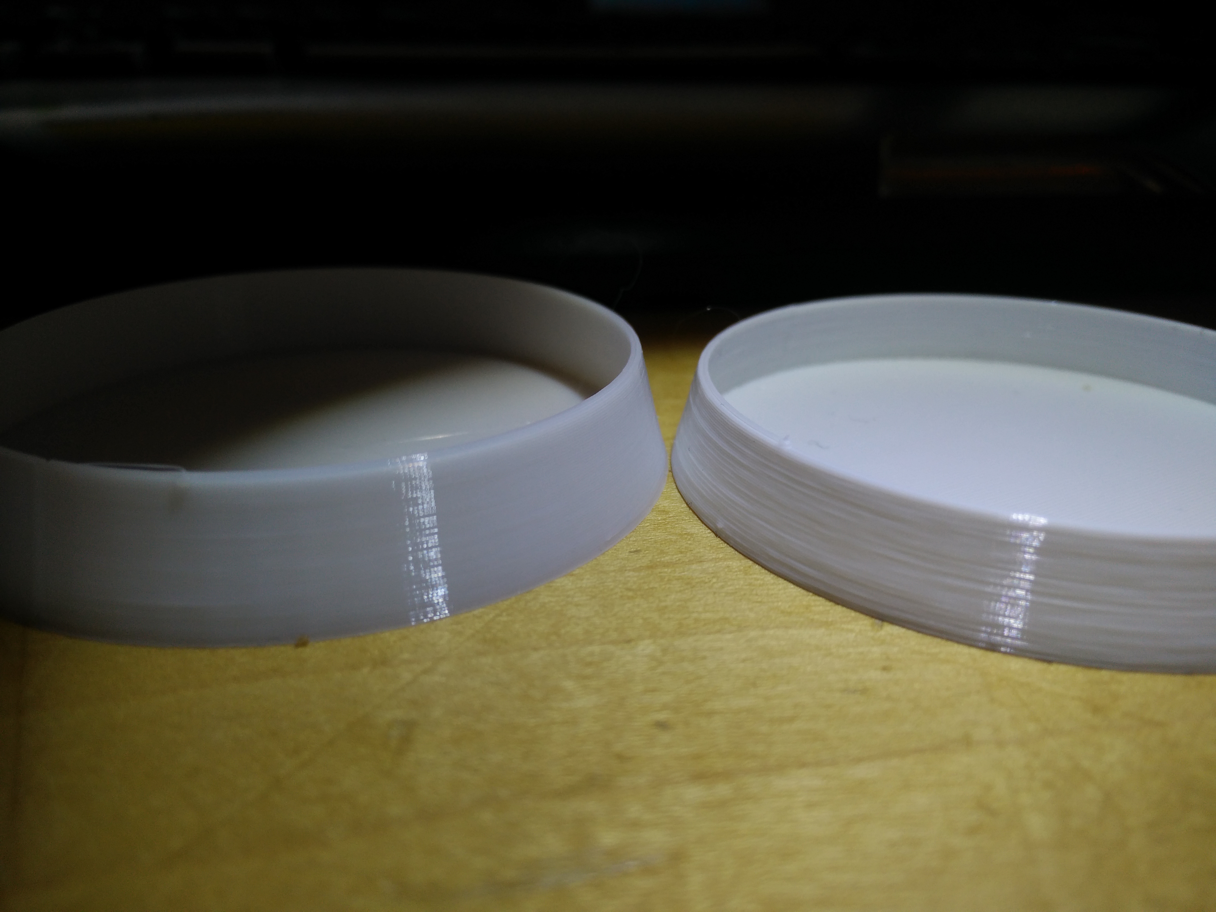
alientek
on 29 Apr 2018
Must be a firmware issue @alientek!
vertigo235
on 29 Apr 2018
@alientek hmm. The left one looks like a semi-translucent white. Can you run your nail up and down the surface of both with your eyes closed and tell me if the roughness feels the same or not.
If it's a brand issue, I must be really unlucky with (I count) 7 different brands of pla having the same effect. The (semi-)translucent ones mask the effect visually but running my nail up and down the layer lines makes clear that the issue is still there.
Found this guys Mk3 print that demonstrate well the hideousness of print surface quality I'm experiencing also (ignore the layer shift):
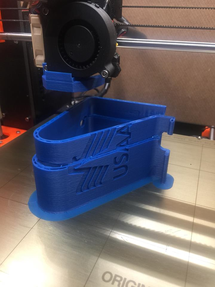
MTJC
on 29 Apr 2018
@MTJC I doono what to say.. the non ESUN brand is way better, almost perfect for FDM.
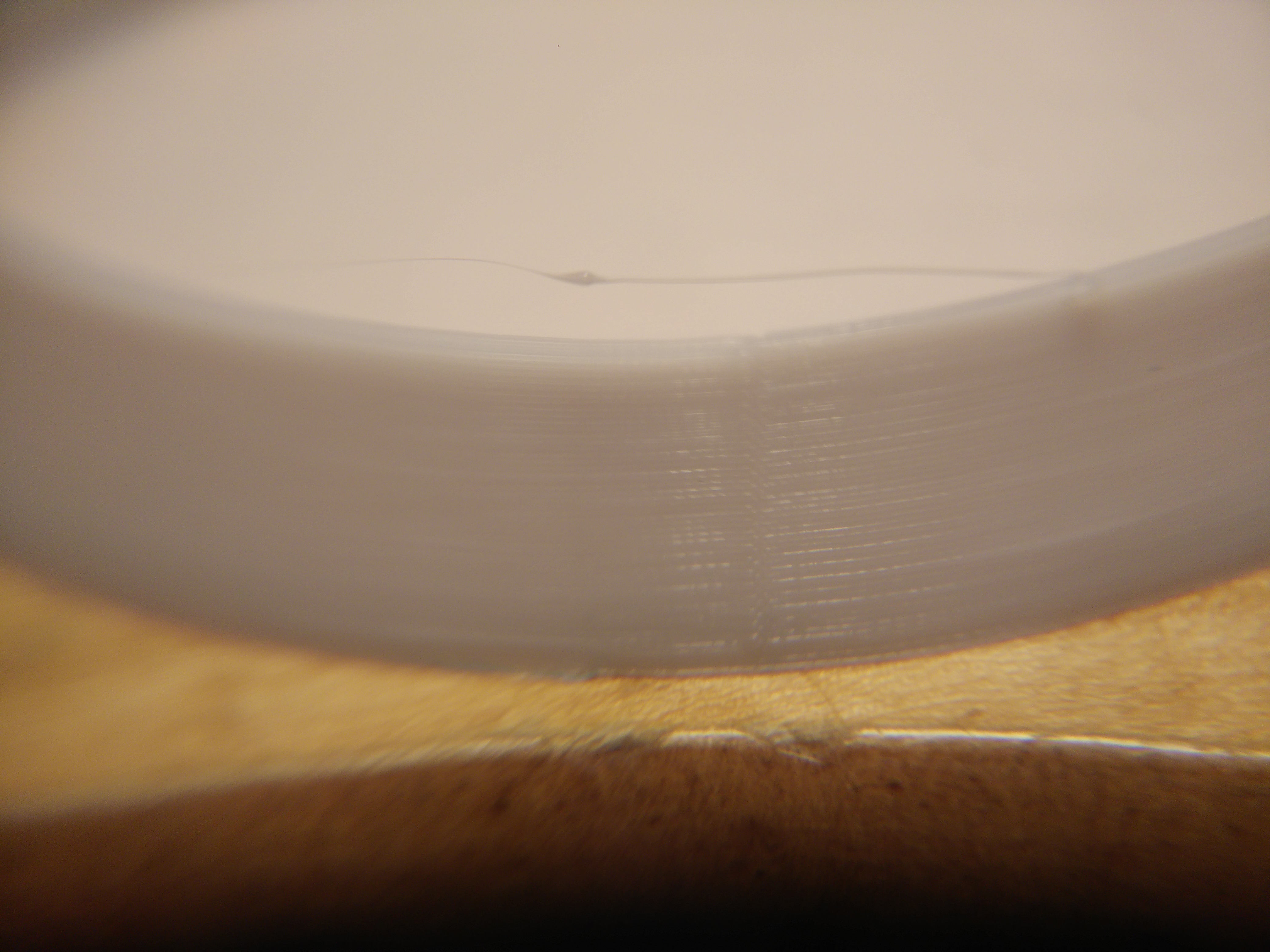
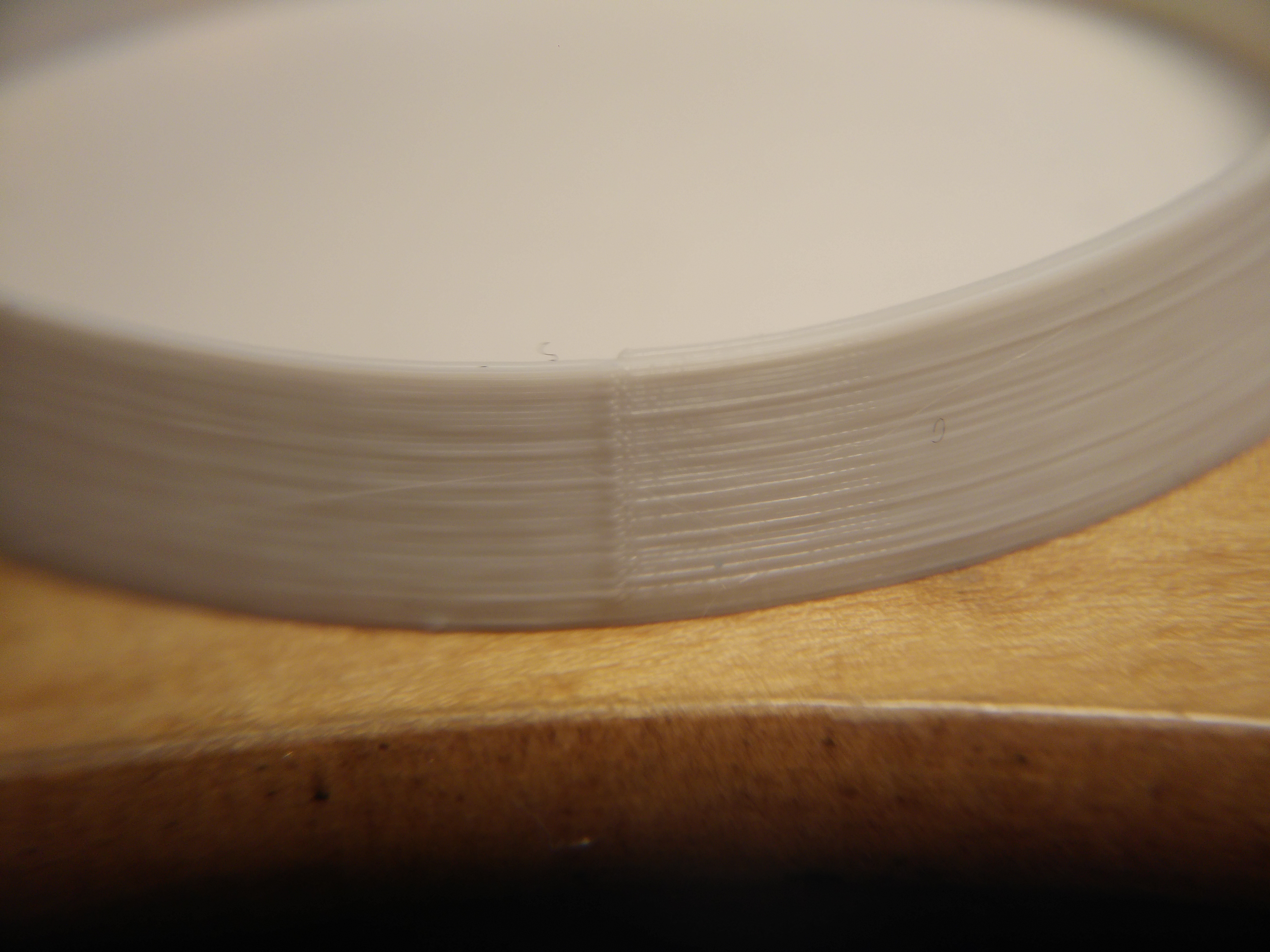
alientek
on 29 Apr 2018
@alientek and what of the finger nail test?
MTJC
on 29 Apr 2018
@MTJC The nice looking one feels smoother, tried multiple feels.
alientek
on 29 Apr 2018
@alientek what's the brand of the filament on the left? Is it a +/-0.02mm filament?
Matts-Hub
on 29 Apr 2018
@alientek at second glance, are you sure that's from the same gcode? The left one looks taller and the conical side/face more vertical than the right one, almost as if it's made of the right stl but scaled up vertically a bit.
MTJC
on 29 Apr 2018
@Quintox303
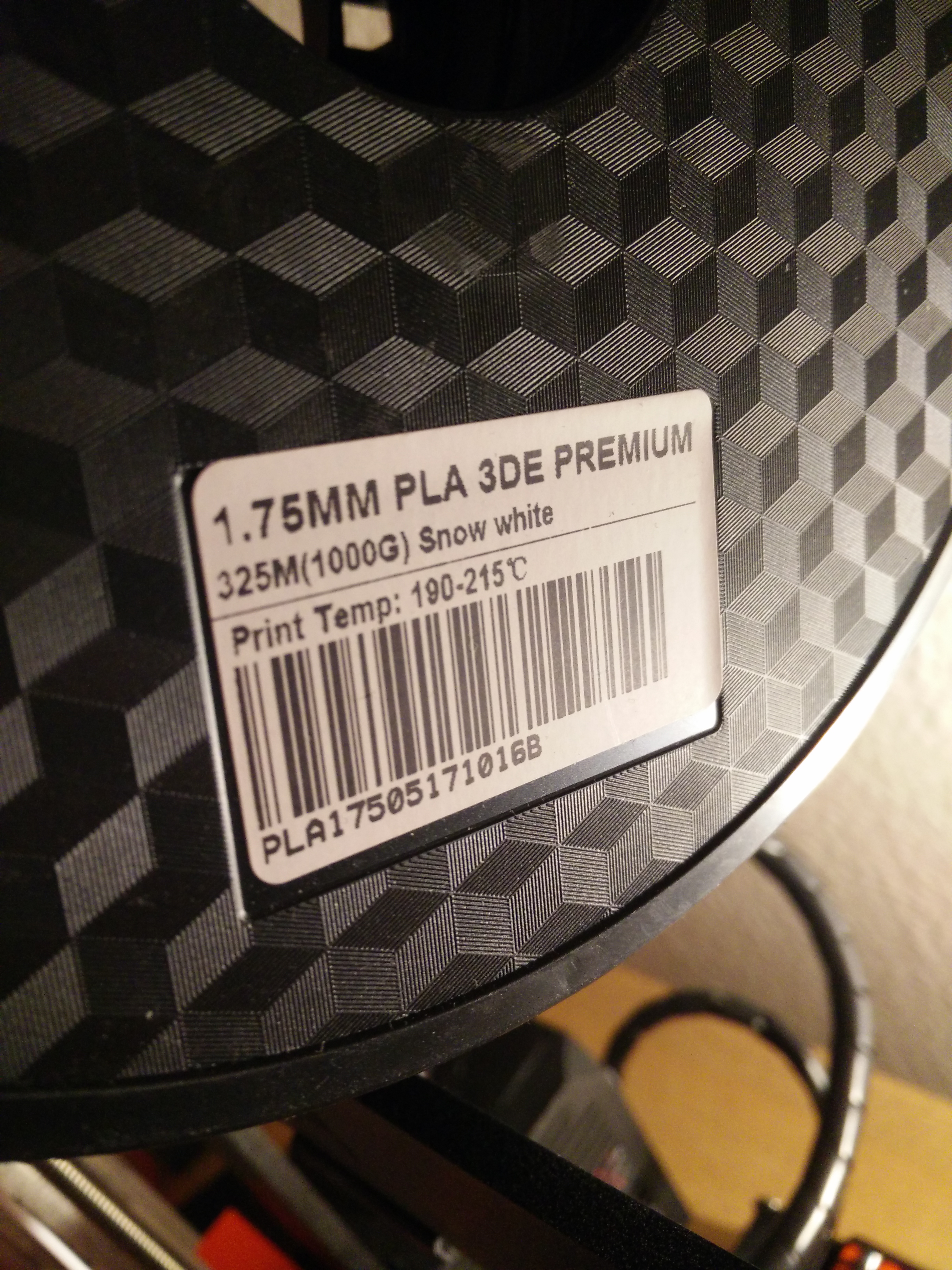
alientek
on 29 Apr 2018
@MTJC i just stopped it at different times
alientek
on 29 Apr 2018
@alientek Right. Ok. Fair enough. Would you mind sharing the gcode file please?
MTJC
on 29 Apr 2018
Good try PR, but not convincing :D
sneaky-tricky
on 29 Apr 2018
@sneaky-tricky ?
MTJC
on 29 Apr 2018
@MTJC Its literally stock slicer profile
alientek
on 29 Apr 2018
@alientek I was hoping to test your gcode with the model you're using on mine with all my pla's. It would make for much better control if I could just borrow yours if you don't mind please.
MTJC
on 29 Apr 2018
alientek
on 29 Apr 2018
Gee almost 400 comments trying to find out whats wrong and i just change the brand xD TADA!
alientek
on 29 Apr 2018
@alientek thank you.
MTJC
on 29 Apr 2018
@alientek My Mk3 has about 8 more hours to go on a print job with the exact same gcode (but adjusted with 95% flow due to mk3 over-extrusion like Slic3r PE does and z and e current changes to match mk2/2s as per devs recommendation) and with the exact same brand of filament (and the exact same spool of it too, having kept it in an airtight bag with desiccant) I used on an mk2 print that I kept. This will make for an interesting test. I also ordered another spool of a brand of golden filament to reprint an Adalinda print (of which I saved the mk2 gcode that I used also) and will test that too. Below is that Adalinda (left mk3, right mk2) but I ran out of the gold and so used prusa silver instead.
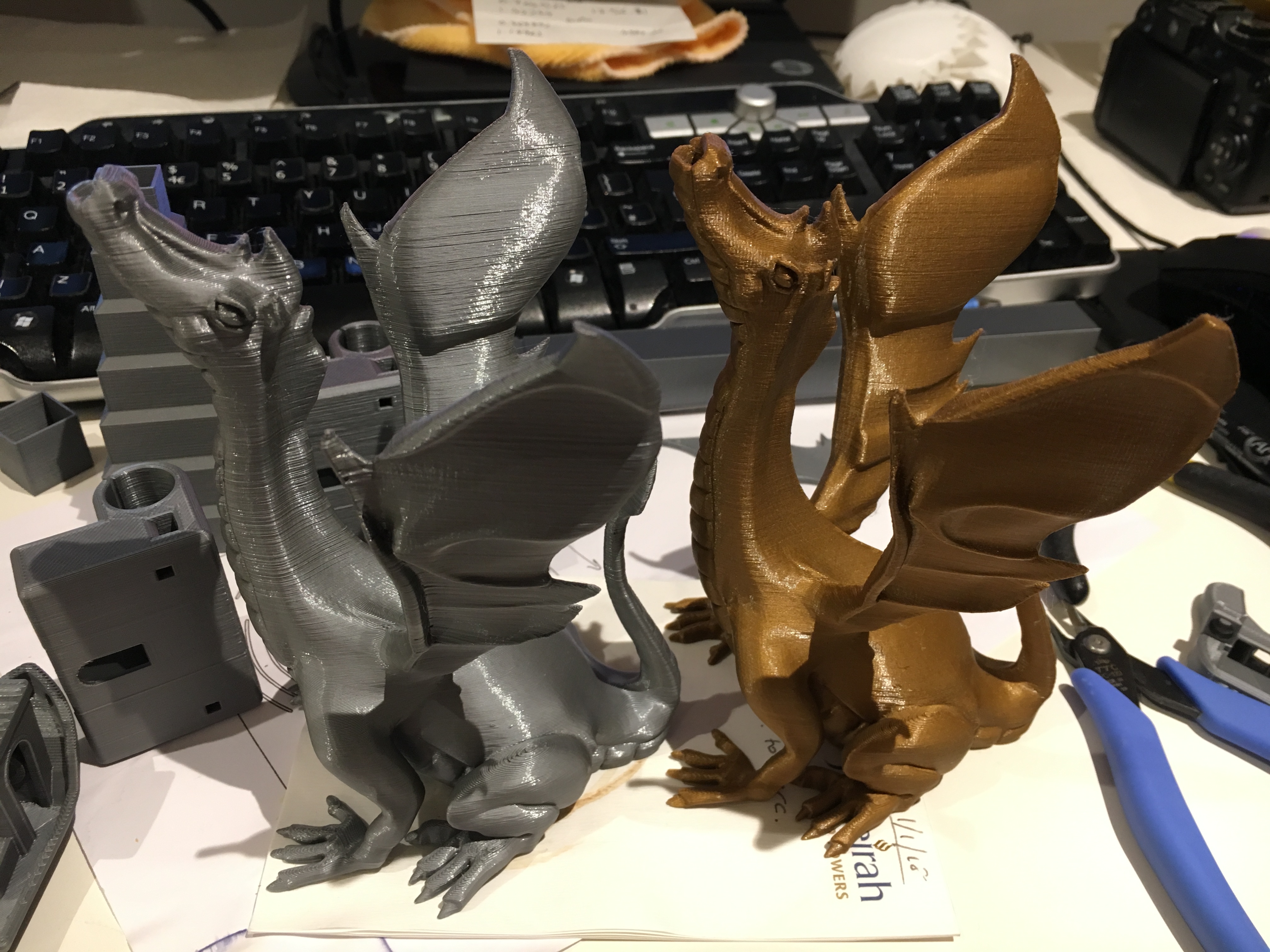
But there is always the possibility that the difference in quality is brand of filament (but I have my doubts but who knows) hence why I've ordered another spool of it and will retest that too when it arrives (should be Monday).
MTJC
on 29 Apr 2018
I'm not sure why there's talk like this is a filament brand issue. We've got tests on mk2s vs mk3 with the same filament showing this only on mk3?
TheBrigandier
on 29 Apr 2018
I have a big difference on single wall cube after the slicer beta and Chris profile on Facebook. Later I will upload pictures. A big problem is coming from extruder motor temperatures, it's very sensitive, but more on that later
venci1ty
on 29 Apr 2018
I have printed the same models with the same roll of filament on another brand printer without this issue. Its not filament problems. We are all aware that some like white and the Prusa silver are worse on any machine but these are consistent extrusion mistakes by these printers. I also have some translucent that helps "hide" the problem but is does not make it right.
Skiidlive
on 29 Apr 2018
@ff8jake
What about your findings with the extrusion multiplier? Are you still convinced of your findings? Did you look into it from a firmware perspective?
I did the e linearity correction today. While it helps with something (moire) it absolutely has nothing to do with our main issue here: unregular extrusion lines.
I know, that has been stated before - I just found it interesting that the problem is really many problems which have to be solved one after the other. I hope we will get there
EDIT:
I have two more ideas:
What about one user, who said that printing very, very fast made the problem disappear - and - what if we would test an old version of slic3r - lets say from the end of 2016, when the MK2 reached its top scores everywhere.
Just two threads that I find interesting to look into.
stahlfabrik
on 30 Apr 2018
@stahlfabrik I'm honestly not sure what to think. Getting rid of the 95% extrusion correction in the startup gcode and decreasing the steps per mm by 5% in firmware seems like it would arrive to the same end without injecting another floating point math operation. It seems strange that it causes the moire pattern to change. I want to say it looks better, but I can't put my finger on how. Like you said, many issues at play here.
Honestly, I feel like the printing at 999% thing is a red herring. I think at that speed, you're actually running up against viscosity limiting the flow rate and functioning as a "filter" so to speak because the filament can only come out so fast. Think of it like an electronic capacitor: When a burst of filament hits it's kept as back pressure, and when a dip of filament hits the back pressure is supplying the need. So your problem seems to have disappeared, but in reality it's just being regulated.
Now I think this is hardly a fix, but it seems to me if we are able to hit against the limits of viscosity by increasing speed, we could also hit the limits of viscosity by lowering temperature. Due to the design of the MK3 cooling lower temps tend to lead to clogs it seems, but it would be cool to try PLA in the usual region of say 180-190 like most printers and see what happens.
TheBrigandier
on 30 Apr 2018
Guys - I'm not getting inconsistent extrusion with my MK3. My kit was shipped the week of Christmas. I've kept up with the "official" FW releases and I've built from code at times. I've incorporated these mods into my printer:
- the updated x-axis printed pieces from PR
- the updated extruder carriage from PR
- I replaced my Y-axis idler with this
- I replaced my z motor mounts with this
Can we at least rule out firmware and point to something electrical or mechanical specific to some printers?
I'm at the pub so I apologize if this is incoherent. :)
rcfsguy
on 1 May 2018
@rcfsguy Where are the pics?
I can't believe this is still an issue...
alientek
on 1 May 2018
@rcfsguy Scrolled back and looked at your prints, am I missing something? They look just as inconsistent as any others posted in this issue?
@stahlfabrik Interesting results attempting lower temp. I started lowering temp in 5 degree increments (fan off the entire time), and as the temp went down the occurrence of "fat" lines went up, noticeably so, eventually clogging completely at 185. This makes me question the temp reading of the extruder, as I have never seen PLA clog a nozzle at 185; however, this may be good news if the fat line issue can be fixed just by increasing temp?
TheBrigandier
on 1 May 2018
@ff8jake I think my standards must be low then. :) To the naked eye my prints look completely acceptable. I would have never given them a second look if I hadn't been following this thread. I'm going to try my test print on my MK2 and see if there's a difference.
rcfsguy
on 1 May 2018
@rcfsguy I believe the pics you have submitted earlier do clearly show the problem we are hoping to rectify in the OP.
Dioblieum
on 1 May 2018
@rcfsguy I know exactly what you mean. At some angles, you'd think it looks great, then the light hits it just right. :)
However... DEVELOPMENT!
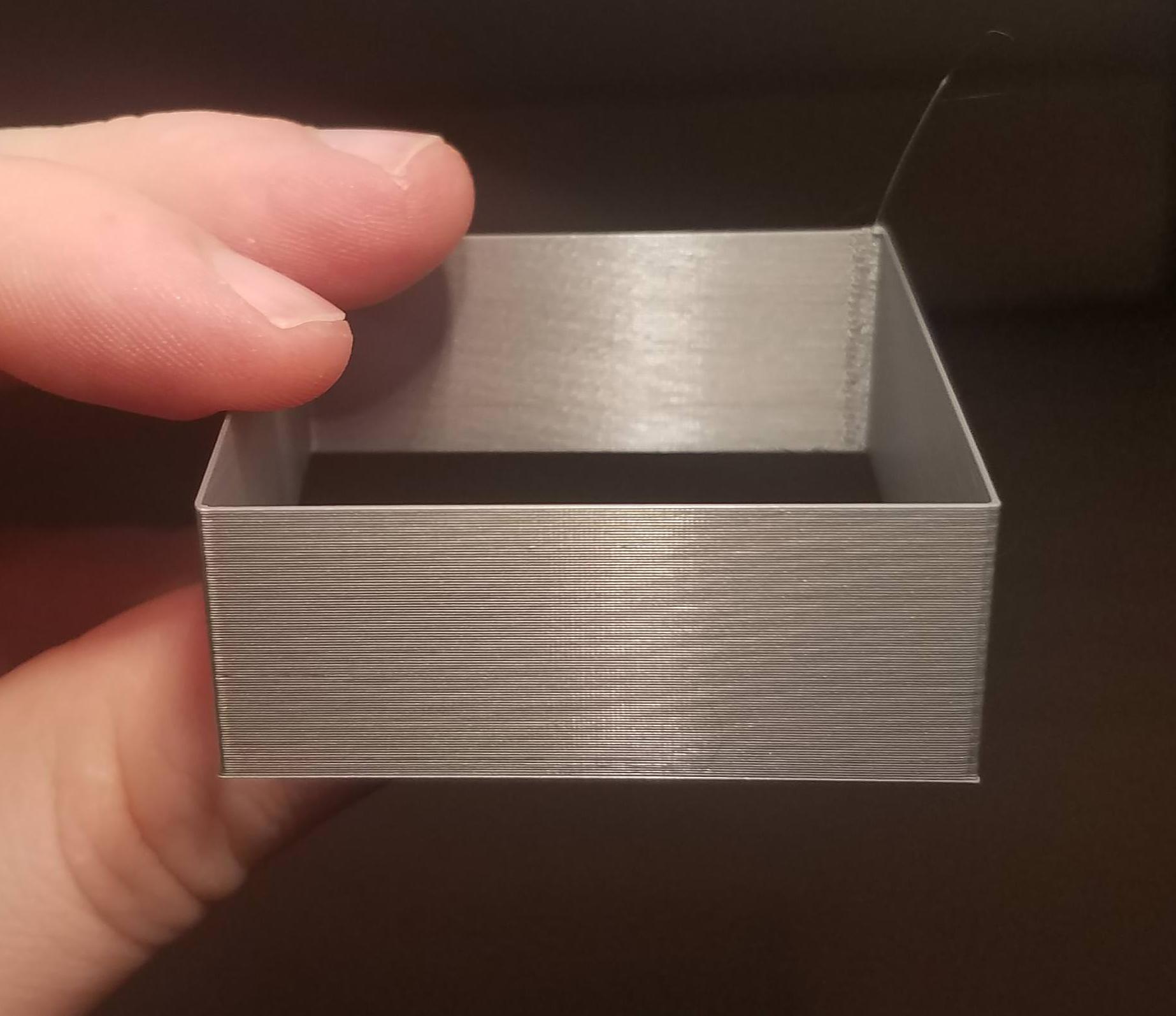
This is the worst angle I could get on this guy. Minus the moire, ain't that pretty? Full view recommended. :)
After getting this to clog at 185 (and distinctly remembering printing PLA as low as the 160s on some printers...) I decided not to trust the MK3's extruder temp reading. I figured if it hard clogged at 185, maybe it was short by about 30 degrees. So the above was printed at 240C, which scares the crap out of me for PLA.
Can we get some others to test this and confirm? If this fixes the fat line issue, then we've got one knocked out and should figure out how we can get that sensor readout more accurate. If this is the case, many of us could be printing things like PETG too cool as well (may explain my crumbly infill with Atomic PETG).
Again, this has nothing to do with small layer time bulges or the moire. This is strictly the randomly spaced fat lines that cast shadows.
Thanks!
TheBrigandier
on 1 May 2018
Just to underline how much smoother the above piece is, I made a crappy video moving it around with indirect light: https://www.youtube.com/watch?v=tIhIaooSYNs - please excuse the knee and lack of focus at the start.
TheBrigandier
on 1 May 2018
OK. Here's the result of printing on my Original Prusa i3 MK2 (FW - 3.0.10):
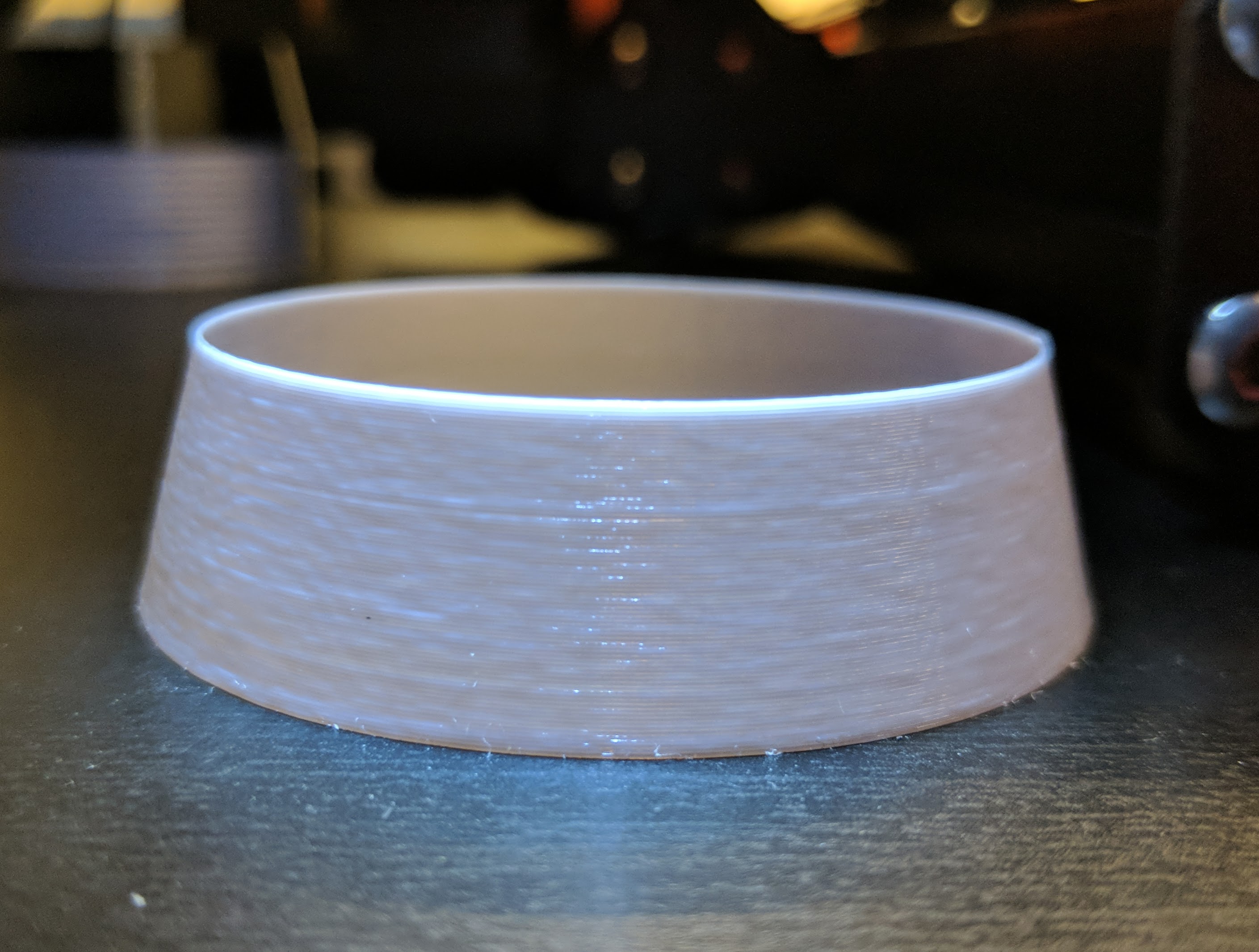
And here they are side-by-side - Original Prusa i3 MK2 (left) and MK3 (right).
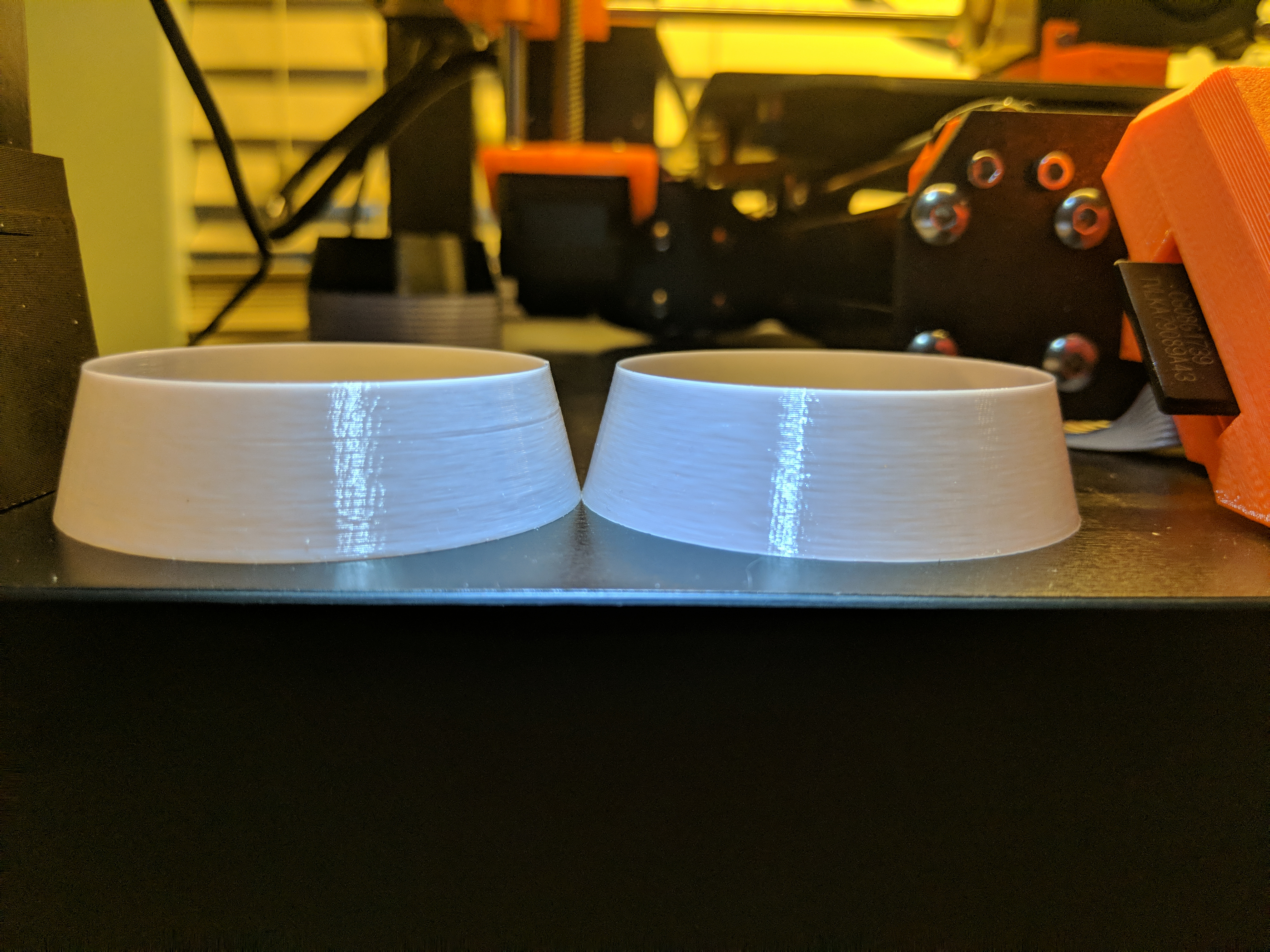
With the exception of the line about 2/3 toward the top of the MK2 print, I can't tell them apart.
Do we have a reference print of what we are trying to achieve?
rcfsguy
on 1 May 2018
I agree PLA prints best @220 and above.
I'm currently printing PLA @225
On Mon, Apr 30, 2018, 8:37 PM Tim Gleason notifications@github.com wrote:
OK. Here's the result of printing on my Original Prusa i3 MK2 (FW -
3.0.10):
[image: mk2]
https://user-images.githubusercontent.com/4092481/39456574-70ce3c7a-4cb5-11e8-8f40-42fae2ffba0f.jpgAnd here they are side-by-side - Original Prusa i3 MK2 (left) and MK3
(right).
[image: mk2mk3]
https://user-images.githubusercontent.com/4092481/39456585-86f21e7c-4cb5-11e8-9dcd-6f18ab3dce06.jpgWith the exception of the line about 2/3 toward the top of the MK2 print,
I can't tell them apart.Do we have a reference print of what we are trying to achieve?
—
You are receiving this because you were mentioned.
Reply to this email directly, view it on GitHub
https://github.com/prusa3d/Prusa-Firmware/issues/602#issuecomment-385569818,
or mute the thread
https://github.com/notifications/unsubscribe-auth/AbY3EOwBObN5c_A9n5hxmaI5ZfAMukKJks5tt65XgaJpZM4TI5uR
.
kwaad2
on 1 May 2018
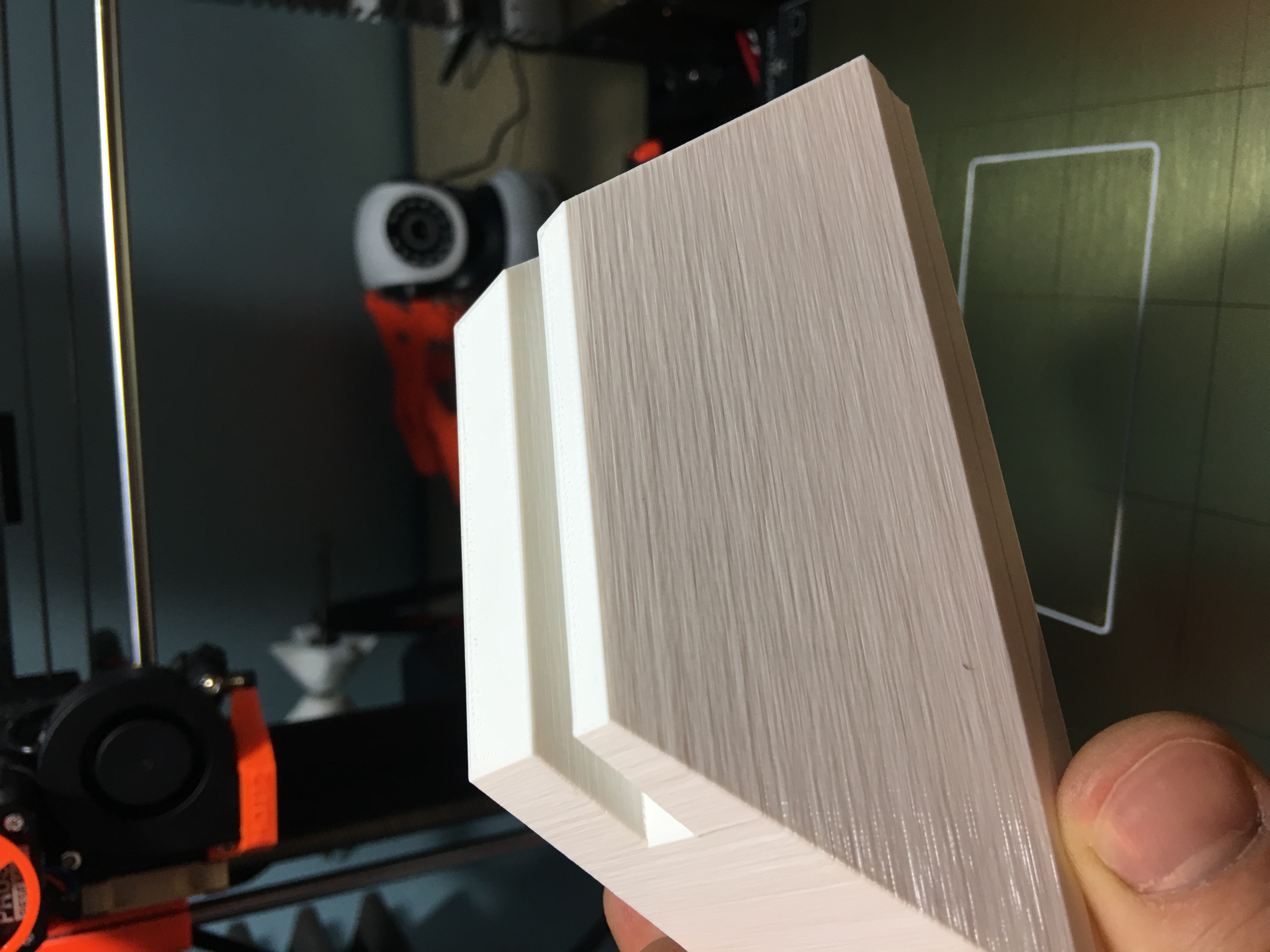
I printed that last night on the RC2 and beta slic3r, I printed the same model when I first got the mk3 and the older one is actually better! Prusa now have my kit printer and replaced it for a prebuilt, it’s clearly not a build issue since I can confirm it’s happening on both printers, even comparing both printers side by side, the issue was the same.
Something I did notice on this print was there are faint vertical lines, you can’t see it on the picture, the older print doesn’t have them.
jonbet83
on 1 May 2018
@ff8jake Ill print some stuff out at higher temps later on, I always found E3D thermistors pretty good but I guess then can all vary.
You can get from E3D PT100 cartridges which I was always led to believe are more accurate and can respond faster to temperature changes, I don't think you can just plug one in to the einsy.
I know it was discussed before but has anyone tried replacing the hot end fan for something other that a noctua with a bit more power even running something off a battery as a trial or taking there printer somewhere cold to see if it is anything partially clogging up? the lower ambient temperature might help
jonbet83
on 1 May 2018
Just a heads up. I was looking at the comments in the Slic3r release and the cooling issue that bubnikv was writing about is only valid for small objects.
Unfortunately the worst case of this issue I have had was on a 7"x7" print of a building. Large print with same issues.
nstis
on 1 May 2018
So I tried increasing the temp all the way to 260 and i didn't notice much change but i was very surprised how well the PRUSA PLA still printed, how can it still at them temps?? I wish i had a thermo camera to see what it is actually reading
jonbet83
on 1 May 2018
What are the main changes above the MK2s? Both, MK2.5 and MK3 do have the Bontech gears and a filamentsensor. Maybe the gears are bringing in a sloppy extrusion or the sensor causes the stepper movement to lag. I am not deep in the firmware, but has already someone checked those effects?
Otherwise, could somebody rollback to 3.1.1 RC5? Afterwards there was a big change in extruding parameters: “Extruder resolution has been changed to 32 microsteps and stepper routine timing has been optimized.”
RacingHell
on 1 May 2018
I'm looking this very long issue since a while. Don't have MK3 but main issue describe here (moire) is exactly what happen going from MK2s to MK2S MMU with bondtech (aka the MMU V1 kit). I made print with my genuine MK2S and redo the same after MMU upgrade and result is similar : great loss of uniformity ... My MMU upgrade kit have been receive on 2017-09-25. Perhaps it could help linking potential source of this issue @ff8jake reference (1st post) ...
 macfly1202
on 1 May 2018
macfly1202
on 1 May 2018
https://www.youtube.com/watch?v=2qr-keUtx7M&feature=youtu.be
First print object you see (2 shell only 20x20x200mm tower), I varied the extrusion multiplier every 10mm up (and every 10mm there is a small recess in the wall put there by me when i created the stl) ranging from 1.05 down to 0.86 (so decreasing by 0.01 every 10mm up the tower). Noticed the change in moire pattern. Got me thinking the pattern is caused by inconsistent extrusion/flow.
To test the theory, I then made another test, kept the extrusion multiplier constant but increased the amount of coast by 0.1mm every 5mm up, thereby incrementally reducing the total path length of extrusion per layer by 0.1mm every 5mm up. I then repeated it but with 0.2mm incremental increase in coast every 5mm up. The results are seen in the second pair of prints in the video. Not only do see the moire pattern change based on the amount of coast but that it's angle is proportional to the incremental change in coast, with the frequency of the macro pattern doubling with twice the amount of incremental coast too.
Lastly, although I did not show it off in the video, I made another stl with the total perimeter decreasing 0.1mm every 5mm so that it would have the same effect as changing coast 0.1mm every 5mm (at least in theory if caused by inconsistent extrusion) and surprise-surprise, the moire pattern on that came out looking exactly the same.
MTJC
on 1 May 2018
I do not have a MK3. I own a MK2s printer. From the early days I had the printer, I've noticed what I thought it was Z-wobble (see first picture). After a lot of tuning and rebuilding and reprinting parts, I found that it was not Z-wobble but the effect of the heated bed on the printing. The model is a 20mm cylinder, printed in vase mode with Prusa's purple PLA.
So, the first photo is with the heated bed on.
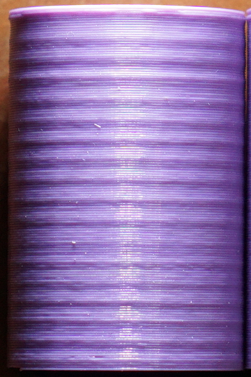
The second photo is with the heated bed turned off.
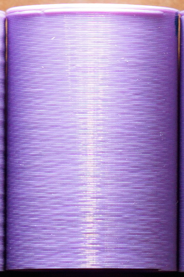
The third photo is with the extruder motor driven by a Watterott SilentStepStick TMC2130 Stepper Motor Driver in slave mode (EEN, ESTEP, EDIR) powered at 24V.
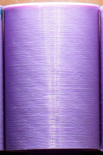
The fourth photo is with the mini rambo stepper driver but with a custom designed extruder that is based on the bondtech gears I took from my MMU upgrade.
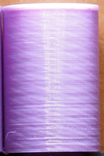
The moire of the 4th photo is pretty similar to the moire that appears to the prints of the MK3, MK2.5 as posted in this thread. So, I tend to believe that the moire originates from the bondtech gears.
Panayiotis-git
on 2 May 2018
@jonbet83 Not a large difference between the display and an external reading. It was tough to get the thermocouple to stay in a spot that would give a constant signal. This was the highest temp I was able to read so I would say it's the worst case for my machine:
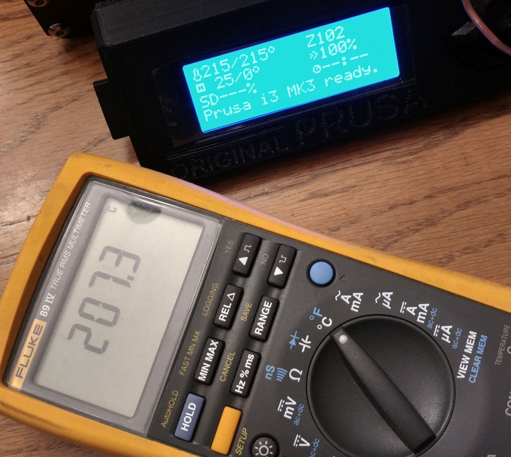
TheDuggem
on 2 May 2018
@Panayiotis-git Ive seen what you shared in the first picture before, its down to the bed set on bang-bang control rather that using any PID control, it causes temperature fluctuations in the hot end, I did wonder at first if that was the cause to our problems at first. I leant that from my ANET
how could the bondtech gears be causing that effect? I did remove half of the bondtechs gears as a trial but only one half, I didn't effect the inconsistent extrusion but I cant really remember about the patterning
@TheDuggem thanks for confirming that
jonbet83
on 2 May 2018
edit: repeat information.
thanks @Quintox303
nstis
on 2 May 2018
@ensitmike That's been tested and made no difference unfortunately
Matts-Hub
on 2 May 2018
Allow me to apologize up front for tossing this out here but we are still all over the place trying to figure this out for Prusa. This may not apply for the MK3 but I recall with some older 3D printers, you would never set the layer height to .2mm. You would always use what matched the steppers. In fact, from personal experience you could get better prints at the next higher height than trying to go to low not matching steps. Does this apply here or could it help?
Skiidlive
on 2 May 2018
I no longer have my MK2 MMU set up, but looking at my old MMU prints, I can see the inconsistent extrusion in them. I originally thought it was a side effect of the Bowden setup. My MK3, OTOH, does NOT show the inconsistent extrusion, just a little moire. Maybe I got lucky?
Assuming that it happens to (at least some) MK2 MMU, MK2.5, and MK3 printers, but not the MK2(S), the only thing they share in common is the Bondtech gears. I wonder if some minor flaw in SOME of the gears, such as the center axis being drilled slightly off center, or some inconsistencies in the tooth diameter, could cause this.
One way to test this would be to print a cube whose side lengths are some integer multiple of a full revolution of the Bondtech gear, to see if a pattern emerges.
 jettoblack
on 2 May 2018
jettoblack
on 2 May 2018
@Skiidlive Are you reffering to the magic number? Such as 0.17, 0.21875
The magic numbers on the mk3, are any Z height divisible by 0.0025.
So 0.19. 0.20, 0.21 are all "Good" numbers.
(you could technically go to 0.1925, 0.195, 0.1975 as well... but why would you?)
kwaad2
on 2 May 2018
@kwaad2 Thank you. That is what I was referring to.
Skiidlive
on 2 May 2018
Hasn't this been tested with the heated off already?
On Wed, May 2, 2018, 8:38 PM MTJC, notifications@github.com wrote:
@Panayiotis-git https://github.com/Panayiotis-git you beautiful,
beautiful human being! You're right. It's the heatbed! Half-way through a
test print that I can already see validates your heatbed hypothesis! Will
post pics soon!—
You are receiving this because you were mentioned.
Reply to this email directly, view it on GitHub
https://github.com/prusa3d/Prusa-Firmware/issues/602#issuecomment-386162863,
or mute the thread
https://github.com/notifications/unsubscribe-auth/AJutFaBVt6Rbnlsf9nTNfSuKp_IbZkYrks5tulFogaJpZM4TI5uR
.
c-stewart
on 3 May 2018
I contacted someone who is running their own printer business. This was their response.
I doubt it's coming from the PWM as DAC, and I'd be surprised if that is what the Einsy is using, since the TMC2130s have built in current limit settings without requiring external voltage ref.
It's more likely coming from rounding errors due to the lack of floating point support in the 8 bit MCU.
Granted, he has no experience with the issues and was just going off our short conversation. Based on his response, our tests can only go so far. I’m more curious if prusa can bring in the big guns and contract someone who specializes in this.
nstis
on 3 May 2018
@c-stewart yeah, you're right. I spoke too soon. Told eric I thought I had verified the problem and he told me the same as you, so i pulled my comment. After the print finished, looks like it hasn't fixed the main issue but does seem like it may have fixed a minor print surface quality issue though. Going to run more comparison prints to confirm.
MTJC
on 3 May 2018
Prusa and big guns? Don't be silly. Prusa Research has a big farm with printers built to print printers parts. Look at their parts quality.
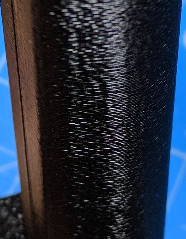
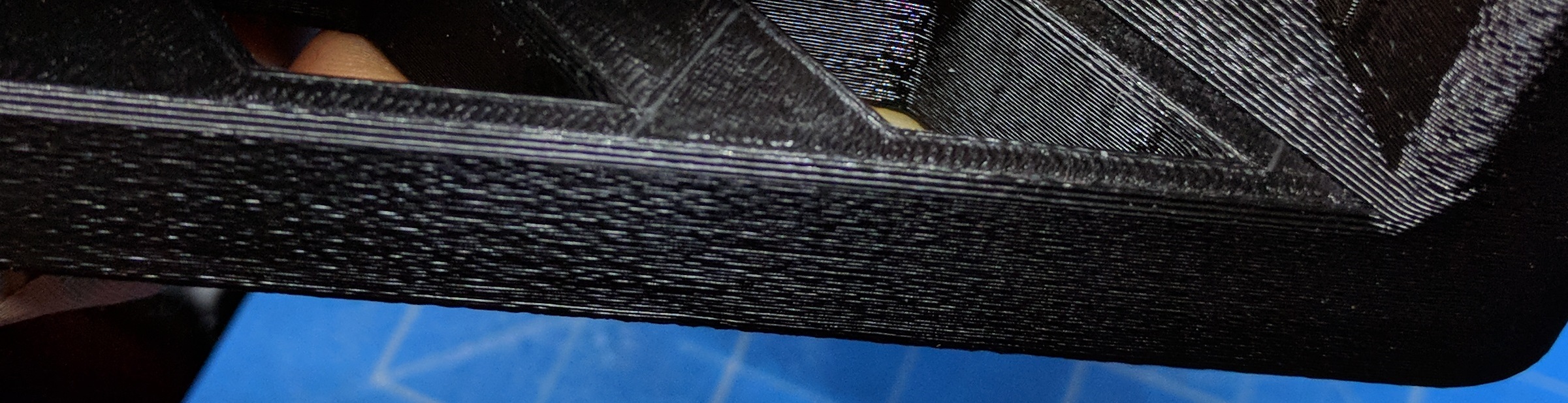
Same issues as everything you see in this thread. Prusa Research job is to build printers that are able to print printers parts. More parts - more printers to sell. You want to print something other than parts? Your fault.
"Since many parts of RepRap are made from plastic and RepRap prints those parts, RepRap self-replicates by making a kit of itself ... you've got a RepRap - you can print lots of useful stuff, and you can print another RepRap for a friend..."
Look at this random mk3 print from facebook:
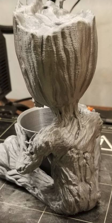
This quality is good enough for parts but not for sculptures.
Just stop fooling yourself and accept this truth. Few weeks ago I had a session with Prusa's tech support guy regarding salmon skin and vertical banding. "I have not heard of any similar issues" - was a response. They don't give a shit about quality of our sculptures, novelty items and trinkets. They know only one thing, how to build printers which purpose is to build other printers.
Now go and print another mk3 for a friend. This is its only purpose :D
sneaky-tricky
on 3 May 2018
Exactly what I get from them same old standard questions. Last week i was told to try printing with a different filament because they had some problems with some. Do they think I omly print in. Prusa silver? The latest email asked me to try the Slic3r beta as if we had no previous discussion about the current firmware and version of Slic3r I am using. Two months and not one thing has changed and nothing from Prusa specific to this issue. Its about time to ship this thing back.
Skiidlive
on 3 May 2018
The reason I've posted the prints from my MK2s was to indicate that the Bondetch gears seem to enhance a lot the surface irregularity. Also, the drop in the quality of the prints is the reason I removed my MMU v1 after a couple of weeks.
Today, I'm receiving at last the MK2.5 upgrade. I intend to execute some tests with the 2.5 extruder and a custom designed one using the MK2 extruder hobbed pulley, to compare the differences in quality.
Panayiotis-git
on 3 May 2018
@jonbet83 Thanks for the suggestion. I've read about the effect of the bang-bang control mode for the heated bed. Unfortunately, this is not the case here as MK2 is using the PID control method.
Panayiotis-git
on 3 May 2018
@sneaky-tricky assuming you do not believe this to be a fake by Eric and that it is indeed not a fake (some people do hence why I explicitly mention this condition), do you believe there is a difference in print surface quality shown here (albeit this is not the best picture to showcase the difference in print surface quality possible between the two generations of original prusa's and hopefully better ones are to come soon....cough please-eric cough XD):
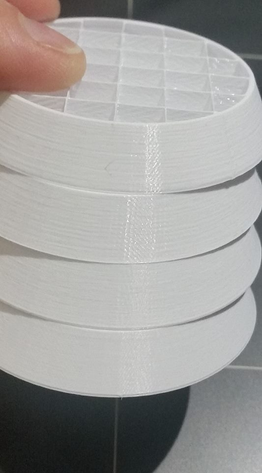
MTJC
on 3 May 2018
Dear customers, we really feel your frustration. We are working hard to solve the issue reported, however this is not a simple topic. We are as well getting frustrated with the reports in this thread. While some some pictures show a clear issue with the print, some pictures are indecisive. With a right lighting and a sufficient magnification, literally any print will look bad. Then there may be filament quality issues (mineral filled filaments are particularly bad), component variance issues etc.
Please, please, when taking a picture, please attach enough of data, so we can print the object. We need your slic3r/s3d/cura profile, your STL, your factory file, whatever it takes to replicate your print as precisely as possible. So please, no picture without an attached STL and slic3r config.
From what I see in this thread, there may be quality issues with the bondtech extruders, with the heat breaks, maybe with the Z axis components? It is hard to say.
@kwaad2
@c-stewart
@rcfsguy
@MTJC
@ff8jake
@jonbet83
Please contact me at vojtech.[email protected] so we can negotiate a printer exchange, so we can get hands on at least a couple of the problematic printers.
bubnikv
on 3 May 2018
Awesome @bubnikv - please keep us somehow updated about your findings.
I remember reading that the mesh bed calibration should be faded out for higher layers? Am I remembering this correctly? Any ETA for this change?
stahlfabrik
on 3 May 2018
@stahlfabrik There is a confusion as of what is the "standard" Marlin feature and what has been "taken over" into the Prusa's firmware. Sometimes the situation is reversed. We quite improved and reworked the bed leveling for the MK2 printer, and then Marlin adopted our code. Then Marlin added the bed leveling fade out, and we did not adapt it yet.
Any ETA for this change?
Once we have a 100% stable MK3 firmware, we can start adding new features.
bubnikv
on 3 May 2018
Will someone please provide a series of reference photos that demonstrates expected print quality from the MK3? Before I reach out to @bubnikv to negotiate an exchange I want to understand if I should be expecting better prints than I'm getting. As I noted in a previous post, a test print from my Original Prusa i3 MK2 is virtually indistinguishable from the same model/gcode/filament on my MK3.
rcfsguy
on 3 May 2018
@bubnikv I think the request for the change by @stahlfabrik was in case the lack of fade-out is one of the things causing the issue.
cjo20
on 3 May 2018
@bubnikv My Prusa is special to me. (well the frame is special) so I'd rather not part with it. I also currently have the JLTX Skeletruder on it, so I can't "honestly" assist with this thread. (I'm willing to help when I can, but as long as my printer has the custom extruder, I can neither help, nor ask for help)
I will say however that I set my E correction to 1.050 (Roughly the same @stahlfabrik had success with) I was planning on running a bunch of test prints to dial it in, but my first "stab" was good enough for me. (I'm in the middle of a 300+ hour print project, so I'm not doing much tinkering)
704
Maybe the default settings could be off on this, given I have a 3.5:1 extruder, and what worked for Stahlfabrik worked for me. (regarding the Moire)
There has been posts about "increasing speed to increase extrusion consistency". I increased my minimum print speed to 30mm/s from 15mm/s, and the extrusion inconsistency appears to be almost "half" of what it was, and looks MUCH better.
I'm not posting pictures of my tests because
- They are NOT printed on the default extruder. (3.5:1 JLTX Skeletruder)
- They are a dark, non-glossy color, and it is VERY hard to highlight the faults.
kwaad2
on 3 May 2018
@bubnikv I sent you an email regarding the printer swap. Thank you for your continued help!
c-stewart
on 3 May 2018
@bubnikv Unfortunately, I have also been fighting very similar issues with my MK3 for the past couple months since receiving my kit. There are fleeting moments with the right filament/settings/model that it suddenly seems great, but then regresses with pretty much any change I make (i.e. model, setting, filament, hardware tweak, etc.). I'll try to be as concise as possible here, because I really need some help at this point after numerous tests and suggestions (from the Facebook group).
[Details]
Firmware: 3.2.0-RC2
Slic3r version: 1.39.2-beta
STL: Prusa "Buddy" model, and "XYZ Calibration Cube" (both unmodified)
Profile (current): https://www.dropbox.com/s/s2008omi20fk4y0/Test%20Config.ini?dl=0
Gcode (sample): https://www.dropbox.com/s/2twcrznq0v5mg2p/Buddy_v4.gcode?dl=0
[Imgur albums]
Buddy model (sequence of recent tests): https://imgur.com/a/aG96kxr
XYZ Calibration Cube model: https://imgur.com/a/nsDYSaW
[Facebook comment threads]
https://www.facebook.com/groups/Prusai3users/922156851302130
https://www.facebook.com/groups/Prusai3users/permalink/922879031229912
[Attempted Fixes]
- updated to latest Prusa firmware and Slic3r releases
- tried PID tuning and reprint
- switched to different filament and reprint
- switch to default Slic3r profile (instead of custom posted on FB group)
- tightened and loosened both X-axis and Y-axis belts
- removed rubber feet for resonance (put thin cloth padding underneath)
- turned model 45 degrees
- turn on linear correction and set to 1.1
- loosened tension bolts on extruder
- purchased and swapped all linear bearings (much smoother and quieter, didn't fix)
- purchased and swapped to another official e3d nozzle (extrudes cleanly, didn't fix)
- installed e3d heat block silicon sock (cleaner, didn't fix)
- reprinted all Y-axis and X-axis parts in petg and installed (helped with tension, didn't fix)
- replaced PTFE tubing on top
- switched to reverse bowden + spool roller solution to reduce uneven drag on spool
- switched PLA brands (only one so far seemed to produce decent results)
- realigned extruder gear and tightened grub screw (using thin metal rod for alignment)
Please help!
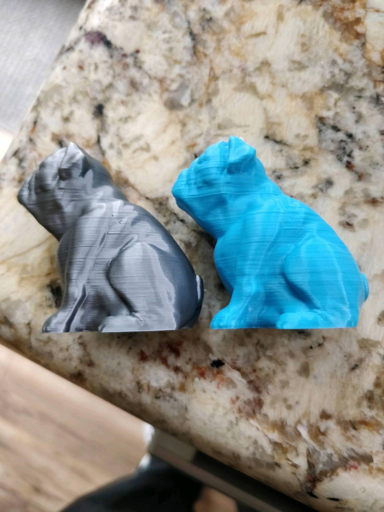
 danielbradshaw
on 3 May 2018
danielbradshaw
on 3 May 2018
@danielbradshaw One thing you may want to check is filament alignment. I recheck mine today after reading this post https://shop.prusa3d.com/forum/assembly-and-first-prints-troubleshooting-f62/has-bondtech-gear-alignment-been-the-source-of-my--t15615.html
I am quite happy with my prints but still following this thread as I won't mind to learn a way to improve them.
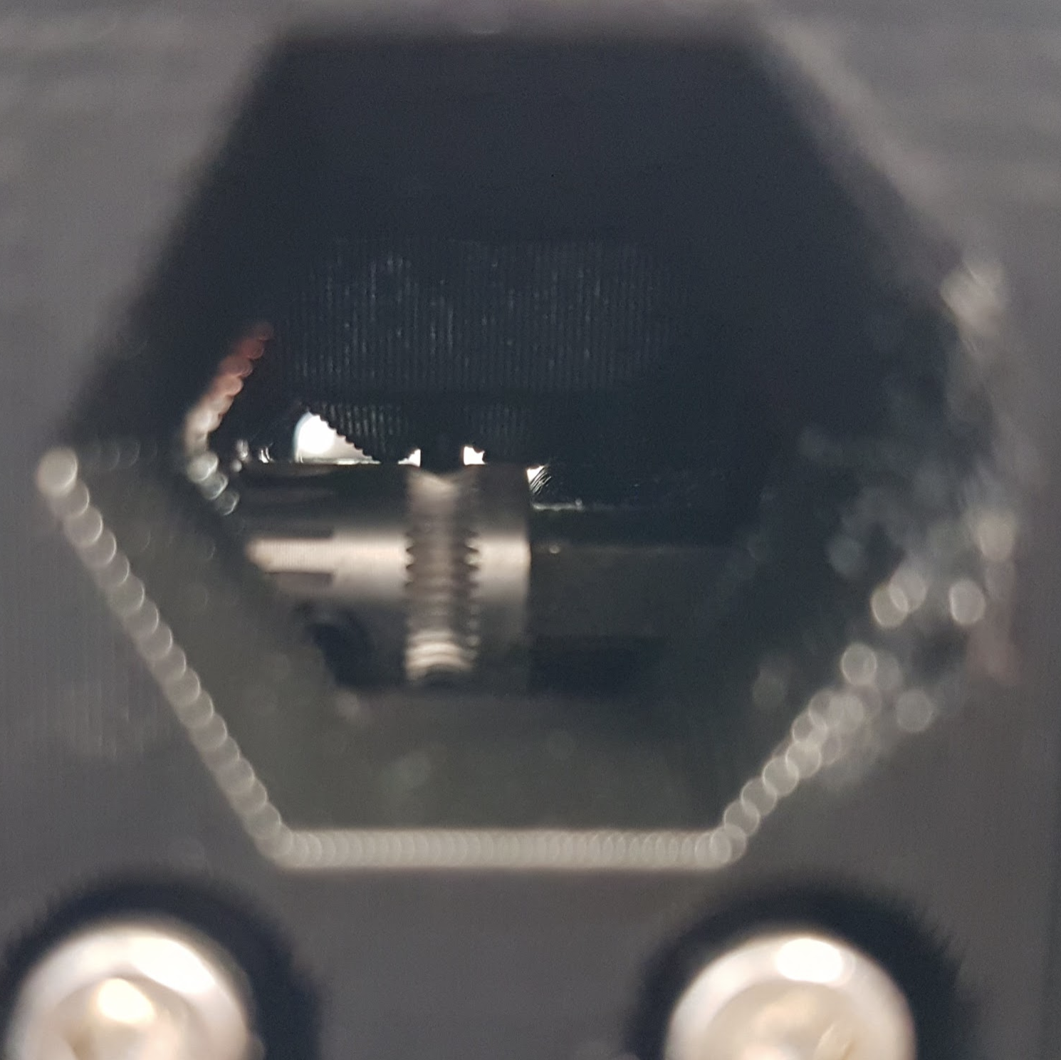
misan
on 3 May 2018
@danielbradshaw that's a nicely formatted report! Let's get more full cases like this recorded.
c-stewart
on 3 May 2018
@misan That's a really good theory, and was one of the bigger problems I had in the beginning. I have since corrected it by aligning with a metal ~1.75mm rod I had around for clearing filament paths on my Maker Select printer (seems to work really well!). I visually inspected it last night and retightened the screw and everything seems okay. It is possible it's still slightly off so I'll take another look tonight to be sure. I'm also trying to focus on my current inconsistency problems rather than all my previous issues (and photos) because I've changed a lot since then (firmwares, profiles, bearings, etc.). I'm going to edit my previous post to mention I checked that as well so it's not lost.
Thanks again anyway for the help :)
danielbradshaw
on 3 May 2018
This discussion is so amazingly off the rails... I am hesitant to jump in, but I do have some commentary to provide as I am experienced in low level AVR development.
First: Given the variance in hardware, slicers, and print profiles on which this occurs there is most certainly a firmware issue that is affecting the motion system in some way that causes a subtle, seemingly erratic effect on the nozzle position, the extrusion rate, or both. Because this issue is indeed very subtle, the preponderance of other problems that manifest in similar ways (slic3r issues, mecahnical design issues, assembly issues, filament issues, environment issues) are confounding what it seems to me is a singular issue that exists on all printers running the MK3 variants of the firmware regardless of their exact hardware (MK3, MK2.5, Custom built, Different extruders, etc.). The key thing to note here is that essentially all of the prints posted which demonstrate these other issues also show the underlying irregular extrusion issue.
Second: By and large I think most here will agree that the print quality overall is pretty good. The functional parts that I print are very usable and getting the flaws to show is a little difficult. But I have a very early MK3 with parts printed on Prusa's MK2 farm, and when I print duplicate parts in duplicate material, the surface finish is unquestionably inferior to the parts that came from the MK2. Parts coming out of Prusa's farm on recent printers appear to exhibit the same minor issues and one might logically assume that they have a fair number of MK3 printers now operating in their farm as well and producing similar artifacts which matches what the other reports here show. That is my personal frame of reference and what draws me to the overwhelming conclusion that the firmware can be improved to equal or exceed the quality that MK2 was producing.
So I am looking at a few things which I know from experience can cause irregular/erratic behavior with AVRs such as ISR race conditions, resource exhaustion, and floating point operations. Most of the "big bugs" so far with MK3 like the 2nd UART trouble, Linear Advance trouble, etc. have been because of these issues. I'm sure Prusa is looking at them as well, and I would encourage anyone with development experience to jump in and learn about these things. I would also encourage those who are seeking mechanical cause and effect to hold your horses.
Here are some suggested methods for auditing this problem:
Use external test euqipment to measure timing jitter of each axis STEP pin when moving at a constant velocity individually and in conjunction with other axes and peripherals such as the hotend, heated bed, fans, etc. This can determine if the problem is isolated to X/Y, Z, or E axis or affects all equally. The expected result of this test is that jitter will be found and hopefully it will be either isolated to a single axis or will occur only in conjunction with a specific peripheral, so more isolated auditing (of peripheral ISRs for instance) can be done.
Audit the code for instances where floating point operands occur and optimize them for execution speed and precision. You should read up on how software floating point works on AVR before you do this, but one such speed optimization of a frequently called function is in st_get_position_mm in stepper.cpp where the floating point divide(~400 cpu cycles) could be easily optimized into a floating point multiply (~200 cpu cycles) by precomputing the reciprocal of the steps_per_mm of each axis only if it is changed (which it basically never is.) I investigated upstream Marlin and found this optimization had been made two years ago. This was just the first instance I found; there are probably many more. We know already that all of the new features of MK3 are heavily taxing the CPU, and float ops are low hanging fruit here. Precision loss bugs are a bit trickier, but they tend to take place where two floating point numbers are multiplied into a large number and then a division or fmod or similar is made in order to produce a small result. With single precision float it is important to arrange these operations to preserve precision. Another more minor problem with floats can occur when they are cast to integers. I note that Marlin introduced a FIXFLOAT() macro to deal with this problem on the LCD but does not seem to use it anywhere in the kinematics (though it may not be necessary)
Well I have gone on long enough; I don't have that much time to dig into the code myself but it's clear there is a lot of opportunity there. Maybe we can turn to having some actual development discussion here and figure this thing out!
johnlaur
on 4 May 2018
@bubnikv Like many others experiencing this issue, my MK3 has undergone some changes/improvements, many that cost quite a bit of cash (all Misumi bearings, sorbothane feet, bed standoff system changed to allow for precise bed leveling), so I don't think mine is really "stock" enough to trade back in. Thankfully there's a lot of stock machines seeing this, else I might think I had made some change to affect things. Maybe I could send it in and you guys could implement some of the upgrades on an MK3S to send back my way later? If not, I'll have to hang onto it and help other ways. 💃 :)
@bubnikv I think we're seeing three issues, and I personally think we've arrived at solutions to two of them.
Problem 1: Small layers have inconsistent extrusion,
Fix: Slic3r bug, this is handled.
Problem 2: Random "fat" layer lines. Not the moire/noisy walls, I am talking about the usual 7 or 8 lines that REALLY stick out. Even on large prints.
Fix?: In my testing, this seems to go away by raising temperature. For example:
I can't help but think that at 205 the filament is viscous enough to cause it to build up pressure until it hits a break over point where it begins to extrude (too much so). At 240 I am no longer seeing these fat lines, maybe because the filament is flowing well enough that the back pressure is much lower and the flow more even? I still question printing PLA at that temp though...
Problem 3: Moire. The universal constant that all of us seem to have.
Fix: I really don't know how this could be fixed besides firmware or electronic hardware adjustment, but I can say that this result https://i.imgur.com/jcXTkA9.jpg would have been pretty amazing if the moire was gone. Also @bubnikv, can you elaborate on @XPila's work with E-Correct in relation to this? #475 shows @XPila working on this very issue, and he posts pics showing three cubes where he adjusts the moire out. Could it be that we already have a solution to this issue, just no instructions on how to properly use E-Correct? I've toyed with it for hours and I can definitely see it affect the moire, but I am yet to figure out how to precisely tune it out using this feature, but @XPila's example seems pretty dang close.
Sorry for the long post, thank you for reading. :)
TheBrigandier
on 4 May 2018
20mm cube in "vase mode". 0.20mm layer height.
CR-10S4:
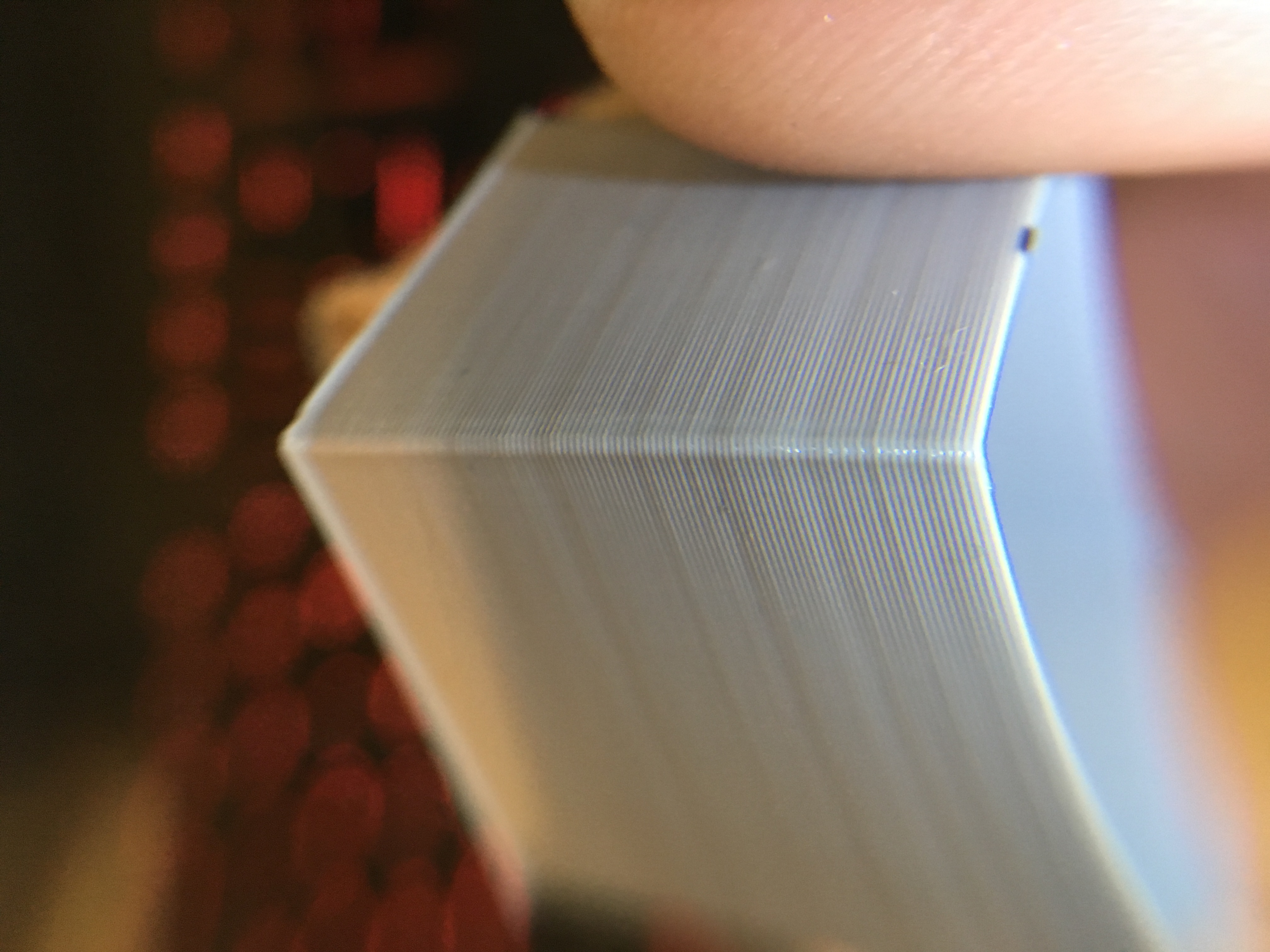
Prebuilt Prusa MK3 Firmware 3.2.0 RC2:
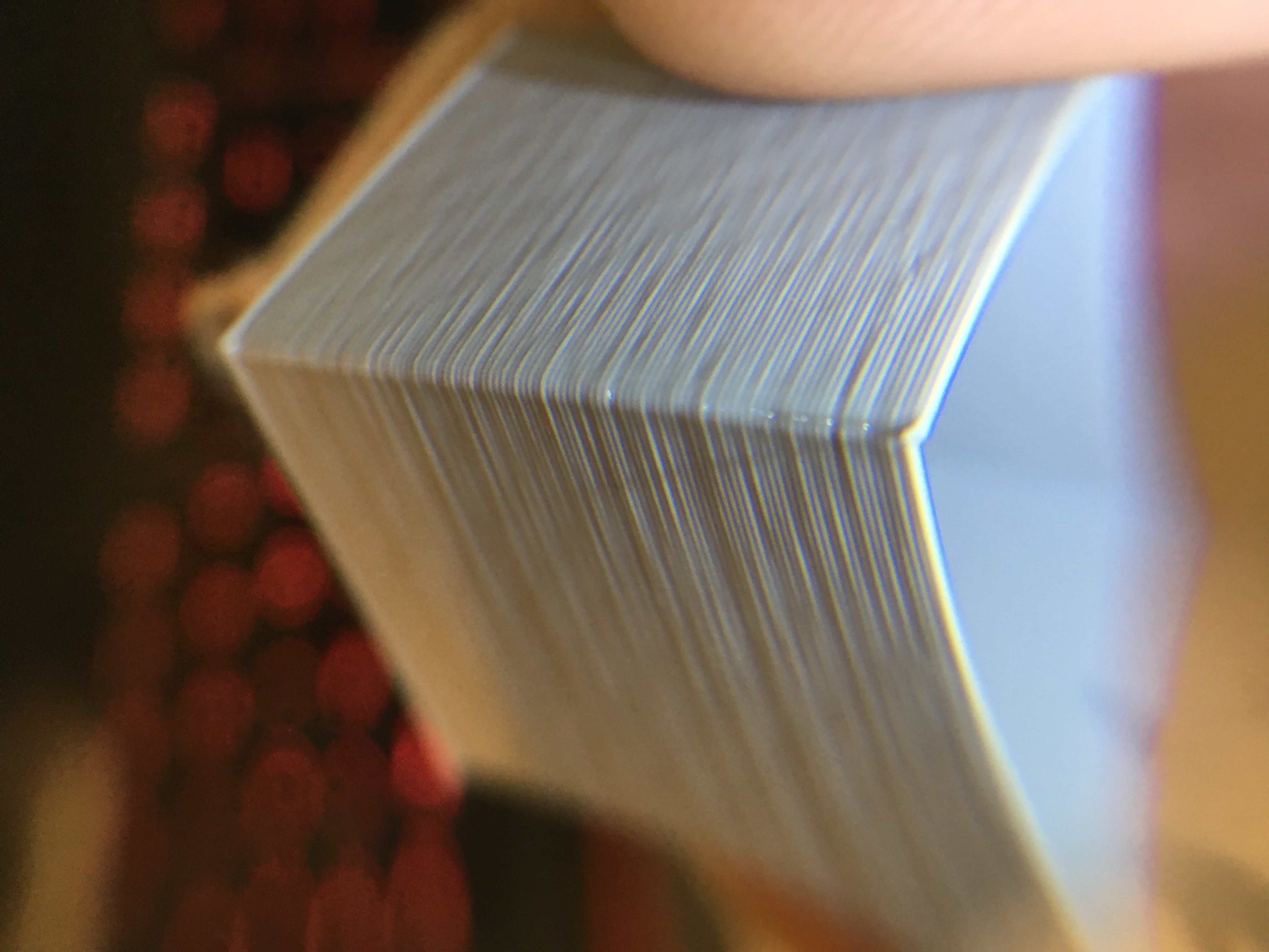
Link to files:
https://www.thingiverse.com/thing:2892579
I would be happy to exchange my MK3 for one that can print the cube as well as the CR-10.
 MarcusAdams
on 4 May 2018
MarcusAdams
on 4 May 2018
@MarcusAdams It makes you want to cry doesn't it? I always try to support Prusa and buy his Original printers, but it makes me cringe when I see an Ender 3 that cost 1/4th of what my printers cost just kicking ass and outperforming the $800 one.
CacikeOtoao
on 4 May 2018
@ff8jake Just in case, I gave your suggestion a try and increased the heat to ~235. It didn't rid of the
artifacting for me (just made it more glossy, as it normally would). Personally I don't believe it comes down to just those 3 issues, because many people are seeing "problem 2" but simply changing the temps aren't doing it, and it's not a moire effect. Back to the drawing board for me :)
@johnlaur Totally agree with your post. At this point I felt the need to comment only to provide another data point for the team if it helped, since I've seemingly ruled out the large majority of obvious causes and there isn't much left aside from some sort of extrusion problem (hardware or software). In my case parts are not only inferior to my Maker Select prints, but immediately obvious to anyone who just looks at the parts in person.
Anyway, I'll try not to clog up this thread with debugging efforts, but anything I find I'll definitely post here and in other groups.
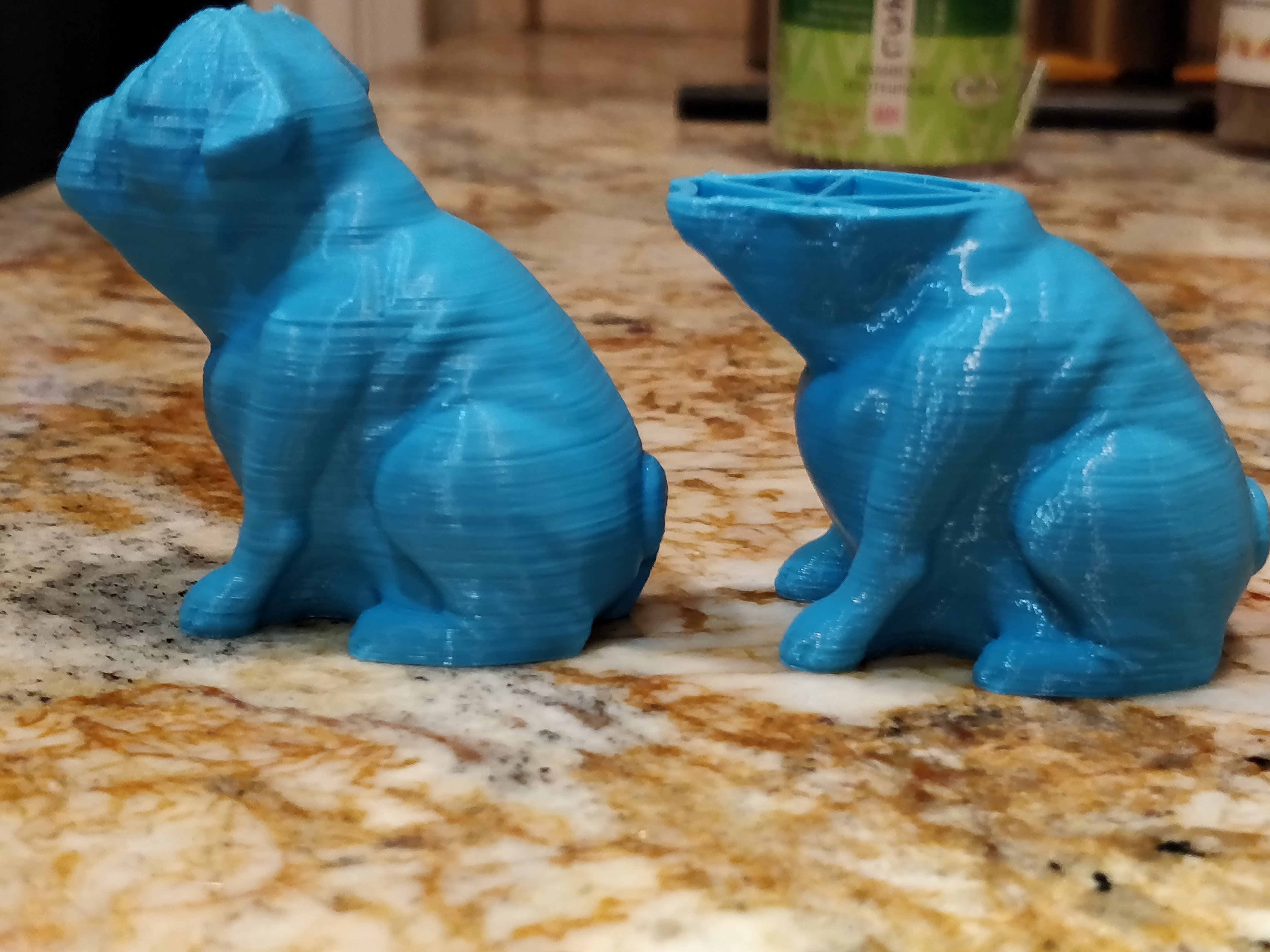
danielbradshaw
on 4 May 2018
@danielbradshaw it's amazing how the over extruded lines seem to occur at almost the exact same layers.
vertigo235
on 4 May 2018
Guys, I don't think is firmware related since someone posted about using vanilla Marlin and the issue was still present. Unless there is a piece of code related to how the TMC2130 operation is handled been share by both flavors of firmware, I don't see been this code related. Having said that, it could be related to the capacity or lack of capacity in the hardware to handle the operations and calculation needed. We have seen as posted here, inferior machines(price wise) perform our reference test cube flawlessly, so how do we go about nailing the differences in firmware, if none of those machines even run our code?
CacikeOtoao
on 4 May 2018
Is there anyone else here aside from Eric with an mk2.5 upgrade that has notice a downgrade in print surface quality like what those of us here are noticing with the mk3 vs our prior experience with the mk2/2s? The reason for asking is, provided Eric is not the exception to the rule, if it’s happening on the mk2.5 too then it’s very unlikely (if not zero chance of it being possibly) caused by any of the hardware differences of the mk3 from the mk2 generation (e.g. einsy board with its trinamic drivers).
For this reason, the problem screams firmware to me as the most likely culprit by a mile.
I still think the best way to test this would be to take the mk2/2s firmware and modify it as little as possible/needed so that it works with the mk3 for testing purposes. If I'm not mistaken, that should just be the mesh/xyz bed levelling procedure/calibration as the location of the 9 points are (iirc) located differently on the mk52 vs mk42 heatbed.
MTJC
on 4 May 2018
@MTJC it might also be the bondtech parts, since they are on both the MK3 and MK2.5
It is either them or the firmware, since it is on the MK2.5 also.
GurliGebis
on 4 May 2018
@vertigo235 I know, right?! That's honestly why it's so frustrating because it very much seems like a big hint as to what's going on, but I just can't figure it out. I had the idea last night that it might be that the model has heavy angles that the slicer considers as a top surface and adds layers of filament underneath. Alas, I printed a completely hollow Buddy model and a plain rounded box, and the issues remain. The box results seem more in line with observations of others in the thread. The printer seems fairly stable which is why I thought it might be an extrusion problem, but the fact it's always in the same places opens the door to either extrusion or some kind of movement/acceleration issue. Still totally lost.
\
https://i.imgur.com/e1YyIQU.jpg
danielbradshaw
on 4 May 2018
I just realized something... Prusa says they can't replicate the problem and that people need to send their printers in... but the parts on my printer that were printed in their farm have the same issues.
They have hundreds of printers with the same problem. They know their parts have it too, right? The higher print temp makes it a little more _melted together_ for lack of a better term, but its there.
nstis
on 5 May 2018
@nstis You skipped my 2 cents, right? https://github.com/prusa3d/Prusa-Firmware/issues/602#issuecomment-386180275
sneaky-tricky
on 5 May 2018
@sneaky-tricky Somehow I missed your post, but yes, you made the same solid point.
I am so confused that they don't see it........
nstis
on 5 May 2018
@nstis They have seen at least parts of it ( see #475 ), but they aren't going to be vocal about it. Better for them to be vague and question the customers' setups until they can find a fix behind the scenes. Pokerface.jpg
I am still toying with E Correct. I followed XPila's instructions in #475, starting at 1.100 and decreasing by .010 until it disappears. It went away on the 20mm cube at 1.060, but was there on the 50mm cube still. Going to start going down by 0.010 on the 50mm cube til it's gone there, and see if it comes back on the 20mm cube.
Considering what @MTJC posted videos of, I expect I am wasting my time.
TheBrigandier
on 5 May 2018
https://youtu.be/ujpMlqvgwdI Check out the video at 6:50 (the Easter egg after). You can clearly see this artifact on the prints.
TheBrigandier
on 5 May 2018
@ff8jake This artifact reminds me the 1st photo of my post https://github.com/prusa3d/Prusa-Firmware/issues/602#issuecomment-385813224. It disappears if I turn off the heated bed and it is minimized (but still there) if I run a PID tune procedure on the heated bed. I have the MK2s. One of the reasons I am switching to the MK2.5 is to see if the MK52 heated bed and the new extruder has any effect on this.
Panayiotis-git
on 5 May 2018
@GurliGebis perhaps but if I'm not mistaken, devilhunter has an mk3 without bontech gears but a geared one and still the problem exists for him. I could be wrong on this though.
MTJC
on 5 May 2018
@MTJC if that's the case, then it would seem like we are down to it being the firmware :-)
GurliGebis
on 5 May 2018
@devilhunter84 can you remind us whether your custom built Mk3 uses a geared extruder or stock Mk3 bondtech please.
MTJC
on 5 May 2018
He has two, one with E3D titan aero, along with a 0.9degree stepper motor.
He said that exact same extruder worked MUCH more consistently on the mk2.
kwaad2
on 5 May 2018
New mk3 kit and starting to diagnose the same issues.
Just a thought.. Is it possible to mod the firmware to run on a 16 or 32bit board that would at least help isolate if its processing power issue?
 jdn-za
on 5 May 2018
jdn-za
on 5 May 2018
@jdn-za sure, since it is opensource.
Would it be a small task? Most likely not, since most of the code is written with the 8 bit AVR platform in mind.
GurliGebis
on 5 May 2018
@kwaad2
I went with the full E3D Titans, not the Aeros.
The Aeros have some... problems, with quicker extruder skipping in enclosures due to heat creep and a very loud fan, coupled with some weak filament cooling solutions and you'd have to move the calibration points away from the endstop distance in the firmware. Also had good experiences with the full Titans, so i went with them.
I've got my MK3 clones on the workbench again for some gimmicky upgrades like additional voltages for raspberry and some lighting, and rerouting the cables a bit.
Since i'm using non "Original Prusa" parts, i'm keeping my stuff out of the spotlight, to avoid having another cook with a different spoon stirring up the messy hotpot here.
Ending next week i should have both machines operational again for some further testing.
I've said the MK3 has some firmware issues that give the layer artifacts, but this seems to be a symptom of multiple causes. Missing mesh bed leveling fadeout does some of it, axis vibrations cause some of it, non-perfectly aligned bondtech gears can cause some of it, default/unoptimized linearity correction causes some of it, unoptimized TMC stepping table causes some of it, very slightly uneven diameter fimalent causes some of it, the PSU being PWM peak driven near it's limit causes some of it, board CPU sometimes being driven near it's limit causes some of it, use of a ungeared extruder causes some of it, temperature fluctuations causes some of it, and linear advance 1.0 with it's super rattling extruder also causes some of it.
(fun fact, multiple people which i printed stuff for told me that the prints looked better before i updated the MK2 to the linear advance firmware. kinda noticed this as well, corners are sharper, but there are lines now where there weren't before.)
But i digress.
Here's the single wall calibration cube printed on the MK2 with almost the same settings the MK3 uses (i think i went with 0.15 on the MK3 by the looks of it, now 0.20 high layers on the MK2)
My MK2 X axis looks ok
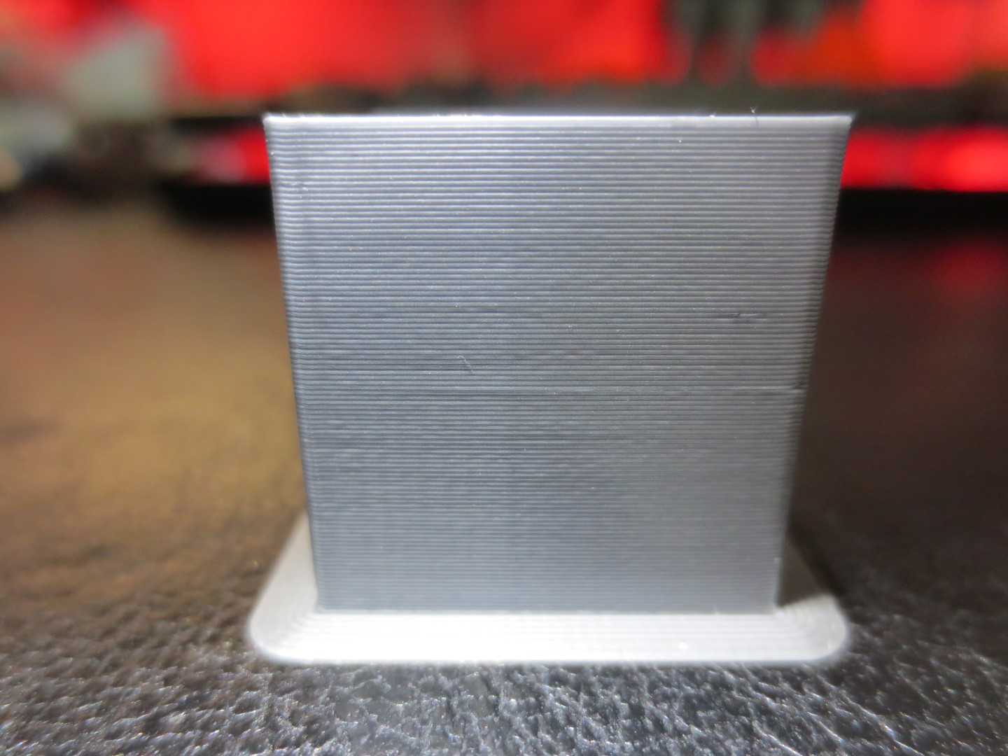
The MK2 Y axis not so...
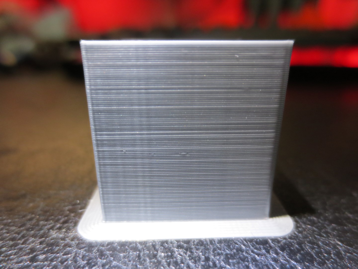
Ironic enough, on the MK3s i have currently the exact reversed problem, with X axis looking awful and Y axis looking flawless.
Another weird this is, i am currently getting better surface finish prints on my MK2 with Cura than Slic3r PE or S3D, so that makes Slic3r a culprit for me as well.
My point being, the majority of problems on this topic for the textured prints are in my eyes software related, which will be ironed out over time. One or two bugs in the firmware, and another in the Slicer. On top of that stacked are various very little hardware issues.
Can't just have all the good sides without the downsides of open source software and hardware after all.
btw, you should see the problems i have at work with the blasted Formlabs Form 2, it went belly up for the third time now. (Repair is always 800$)
devilhunter84
on 6 May 2018
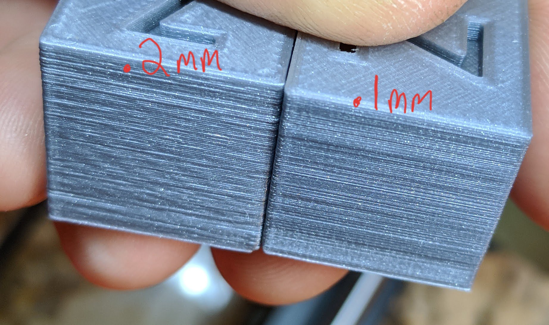
Just adding another example of inconsistent extrusion on MK3. Solutech Silver PLA. I love the MK3 for all its features and it is very dimensionally accurate but both my <$200 printers can print the same material with much nicer looking perimeters(not that they don't have their own flaws and I much prefer the MK3, I just hope this is fixed soon).
Edit: Just a side note, current Firmware and Slicer versions seem to make little to no difference so far.
 TheBlueGreen
on 8 May 2018
TheBlueGreen
on 8 May 2018
Tonight I set up a reverse bowden on my MK3. It tightened up things a little more, and what inconsistency I have left seems to correlate in angle to the moire.
I have also reverted back to the stock E steps with 95% extrusion rate and believe my quality has suffered from it.
Tomorrow I will reflash with the E steps down by 5% and flow at 100%. It will be interesting, as I will likely need to figure out E correct again as well.
TheBrigandier
on 8 May 2018
@TheBlueGreen The quality difference is very sad :/
alientek
on 8 May 2018
So I have been testing in stealth and slowish movements and for the most part on complex models the inconsistent extrusion doesn't seem to be there as much as in the pictures posted here, moire effect still very much is.
Could this be a side effect of printing models that don't have the hotend traveling in straight lines for as long?
I printed this bearded yell at 60mm/s 0.4mm nozzle, 0.2mm layer height (just under 9 hours print time) extrafill gold happens pla @ 220c
Decided to try the youthful scream model at 50mm/s 0.25mm nozzle, 0.1mm layer height (just under 21 hours print time) prusa beige pla @220c
Both in stealth mode with supports, using Chris's petg profile with small tweaks.
Ps: I can't seem to attach pictures from my phone, will update in a bit.
jdn-za
on 8 May 2018
@ff8jake Would you please summarize for us what exactly did you do to be left just with the extruder moire? It will certainly be very useful to us and to our other customers.
As far as I understand it, your layer inconsistency was fixed by the reverse bowden setup, indicating that the uneven layers were caused by uneven drag caused by the filament spool / filament spool holder?
@nstis They have seen at least parts of it ( see #475 ), but they aren't going to be vocal about it. Better for them to be vague and question the customers' setups until they can find a fix behind the scenes.
I have printed couple of whistles yesterday where others complained about the uneven layers. I printed most of them on our MK3 printers and they looked good in my opinion. Surely if you magnify the pictures enough, you will find many flaws on the tiny printed objects. Interestingly enough, from desperation I have fitted the MK2 extruder head on a MK2.5 printer with the Einsy board configured to run an old time proven MK2 firmware with very minor modifications to run on the Einsy board. Interestingly enough, this configuration produced the strongest moire effect for the whistle. That is, the Einsy configured in a MK2 emulation mode and with the MK2 extruder, excluding most of the MK3 features.
There are just too many inputs, that may combine to produce similar end effects on the print quality. For example, the moire I was seeing on this MK2.5/MK2 test machine may be caused by a slight over extrusion. Indeed, the excess material has to go somewhere and it is quit possible, that the excess material is released periodically, when it exceeds some pressure limit.
The uneven layers may be caused by the drag on the filament (spool holder, spool), by the Bondtech wheels misaligned with the filament, maybe by some quality issue of the Bondtech wheels, maybe by the quality issue of the heatbreak, maybe by a low / high temperature of the hot end due to thermistor / heater / heater PID issues, maybe the uneven layers are caused by the play in the X or Y bearings or the Z lead screw, maybe the Z motors are not strong enough to keep the motors in position, also the filament may not have consistent diameter, and the mineral filled filaments do not flow quite consistently. Now tell me, which one is your issue?
In regard to the extruder linearity correction, as far as I am known, our results are inconclusive. On some machines you will get improvements, on some machines you will not. My personal opinion is, whether the linearity correction will work may be related to the parameter spread of the stepper motors (how precisely are they fabricated, how precisely are their coils wound). I suppose there is a calibration curve to fit all the extruder motors, but it will require to vary multiple parameters, which will be very difficult to do by a mortal.
bubnikv
on 8 May 2018
I'd like to see the whistles mentioned with an above light source. I know this brings out the issues more than you'll really see under normal conditions but the fact is that other printers don't have this same pattern of varying extrusion. I find it very hard to imagine that this is caused by a quality issue when so many people have the same issue (I am almost certain that everyone has this issue they just don't know any different or don't care enough). If it is a hardware quality issue then it is a widespread and serious issue in my honest opinion. I have yet to see anyone post pictures of a MK3 that doesn't have this problem (if the pictures provided are correctly positioning the light to show the issue).
[Sorry if anything I say sounds rude, only trying to be constructive.]
TheBlueGreen
on 8 May 2018
First, @bubnikv we really appreciate all you've done. You have a big community with lots of complaints and you've kept a level head--keep it up, mate. Hope Prusa is buying you a six-pack for the weekends.
Most of us understand the very complex process of solving the issue. The issue needs to stay on the table though. We just have to be straight up about it. We can't have any more talk about it as being picky or not picky. It's also not about looking too closely or under a magnifying glass or filament type. At the end of the day if we can hold up MK3 prints next to a CR-10 (a printer that is inferior on many levels IMO) and the prints aren't as good... something has to be wrong. All of the quality control, tested parts, and genuine components have to make a better printer (or at least an equal printer).
That makes the post above by @MarcusAdams really important for this conversation. It's the same filament, same conditions, I'd assume same settings, but no matter how we look at it, the CR-10 print is far cleaner.
I also know the dev side really digs deep in terms of time investment and most of us know nothing about it, but some of @johnlaur comments sound like potential bugs could go far beyond the physical and mechanical focus of this whole thread of conversation. The very "maker" driven exploration done by the community is great but some of the smarter and more knowledgeable people tend to think the Prusa firmware might have a fatal flaw. I don't know how many resources you have or how many people are helping you but I hope the code is being looked at more.
nstis
on 8 May 2018
@bubnikv I wouldn't say it's fixed it, it's just made the effect look less random. The way the extruder's weight hangs forward from the X axis rods (and considering how you can flex it upward by hand pretty easily), I suspect _some_ artifacts were because of filament lifting it and confusing the other issue. Like we've all said many times in this issue, it looks like more than one problem at once.
https://www.evernote.com/shard/s211/sh/701c36c4-ddd5-4669-a482-953d8924c71d/1ef992988295487c98c268dcdd2d687e - this is a great read. There's a bit towards the bottom about reverse bowden that encouraged me to try it.
@bubnikv Unfortunately I got the reverse bowden completed just before bed last night and got off one test print. Once I get through work I will see if I can do another test and post images. I almost posted a pic of it, but I would like to post one with the adjusted E-steps as well. Last night's test looked less random, but still worse than my adjusted E-steps piece ( https://i.imgur.com/jcXTkA9.jpg ). Will update in about... 12 hours or so. :)
TheBrigandier
on 8 May 2018
I have printed many times including testing the whistle using only a few feet of filament and no spool on the frame with absolutely no difference in the quality. I'm not saying that sometimes it may cause additional issues with print quality only that it makes no difference on my machine when I removed it from the equation. I use a frame mounted spool holder with bearings.
Skiidlive
on 8 May 2018
@Skiidlive Yep, like I said, I don't think it fixed the inconsistent extrusion. I _do_ think it was causing some random artifacts in addition to it though.
TheBrigandier
on 8 May 2018
I also printed without a filament spool on the MK3 to eliminate the drag as a problem. The photo shown is without a spool. I had about a meter length of filament in the extruder, and I watched it the whole time to make sure there was no issue feeding:
https://github.com/prusa3d/Prusa-Firmware/issues/602#issuecomment-386480645
The settings are the same between the CR-10S4 and MK3 prints. The only difference should be the size of the bed (location of the print). Same spool of filament, same speed, same temps, etc.
I did use Cura 3.2.1 instead of Slic3r, but if the printer is dependent on Slic3r, that will have to change or be advertised to the user.
I don't believe that I have unreasonable expectations about the (surface/wall) quality. I don't care about the surface quality on practical parts, and I don't print figurines. My main concern is lithophanes. I've printed two 15 hour lithophanes on the MK3, and neither were passable. They were put in the junk bin. My CR-10S4 prints a decent lithophane every time.
I expected better quality on my MK3 than the CR-10S4 due to the MK3's leveling, Bondtech gears, E3D hot end, and microsteps. I'd also rather use the smaller MK3 which heats up much faster to be printing anything small. If it doesn't serve that purpose, if I can't print a passable lithophane on the MK3, it's going to have to go back. You're going to have to tell your consumers that it doesn't print lithophanes.
I was asked by Prusa support today to try with Slic3r, so I will try that and report my results.
MarcusAdams
on 8 May 2018
@MarcusAdams MK3 is a different animal from the CR10. MK3 is a direct drive system, while the CR10 is a bowden setup. In my opinion, you should not use the same settings for both the machines. Namely, the direct drive setup works best with short filament retraction settings, while the bowden setup requires longer retraction settings.
bubnikv
on 8 May 2018
@bubnikv , despite the fact that they are different animals, I used the same settings. I used a 1.5mm retraction setting for both, which would favor the MK3, yet it's moot, since it was printed in vase mode and didn't use retraction.
MarcusAdams
on 8 May 2018
Worst one yet
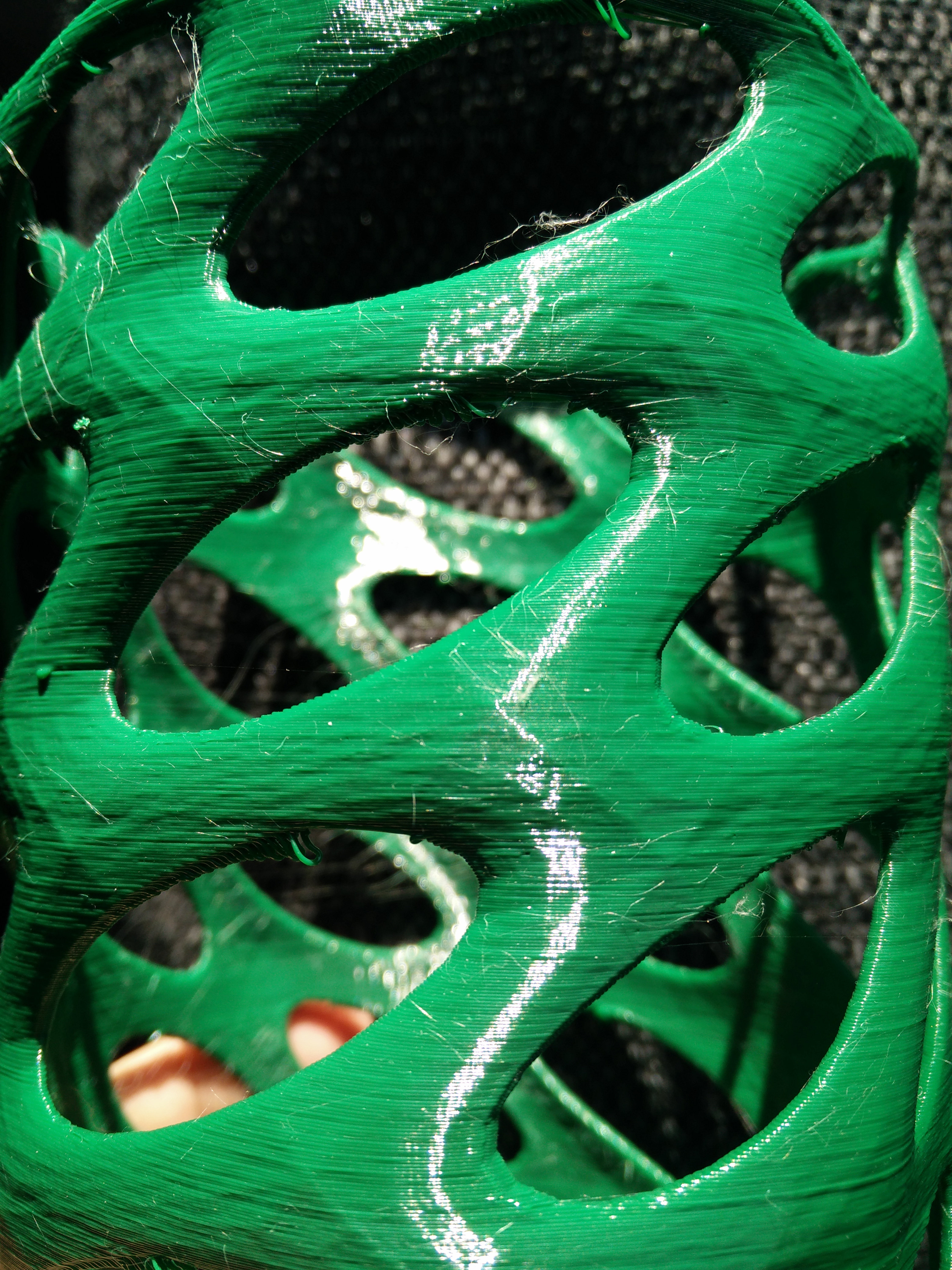
alientek
on 8 May 2018
As I understand the situation, there are no exceptions to this problem and even printed parts from Prusa shows it yet there are people swearing they do not have the problem at all. I have yet to see proof but if they exist, wouldn't Prusa want at leas4one at any cost to study?
Skiidlive
on 8 May 2018
Why are you guys not adding gcode and slic3r settings to your pics? How should anyone check what happens if you do not provide the necessary information? I do not want to see any pics here anymore if it isn't with information on how to reproduce... I mean no one has the interest to make bad mood against another company, right;-) And even if all pics are legit - how should the devs at Prusa recreate your problem without ANY information? It is not how bug fixing works. This is GitHub.
stahlfabrik
on 8 May 2018
Ive been E mailing .gcode to @bubnikv with pictures so they can reproduce, I wont post more pictures here nothing has really changed since i got my MK3 a few months ago. I do think anything printed should be using the default PRUSA profiles which they provide so everyone's the same settings and slic3r. Ive pretty much gave up on testing now as i cant think of anything else to try. im happy to do some test prints if anyone needs it
jonbet83
on 8 May 2018
I recieved a new gcode file from Prusa yesterday to print and although it looked better, still had the same issue. I also printed in some Rigid Ink which was slightly better. I case anyone wants to try...
https://drive.google.com/file/d/0B-eoNgU4ZshvSGN2X2dTcmJPRTd1UnlLYUtSdE1MNk94THZV/view?usp=drivesdk
Skiidlive
on 8 May 2018
The drive is not public, couldn't download
 workinghard
on 8 May 2018
Skiidlive
on 8 May 2018
workinghard
on 8 May 2018
Skiidlive
on 8 May 2018
@stahlfabrik I'll include my settings on the next one, but beyond setting perimeters to 1, infill to zero, and top/bottom layers to zero, they are stock Generic PLA preset.
Also it's a bit of a futile exercise isn't it? I am yet to see an MK3 print that doesn't show this artifact, exempting geared steppers and the crazy 999% speed cube.
I would LOVE to see Prusa print one of these tests and show us they aren't experiencing the issue. Just a single wall cube with light shining from above like we've demonstrated so many times.
We've yet to find a single user who doesn't have this issue when doing the test, and I suspect Prusa will have the same issue if they try themselves.
TheBrigandier
on 8 May 2018
@ff8jake I would love to see that, too. I still like to believe that not every MK3 has it - like Toms3D review suggests (e.g. 6:36, and later at 7:08 Toms statement) - I am just watching it again and the prints look pretty. Lets not forget we swim in our bubble of affected users:-)
I also heard from a guy who went to a maker faire last weekend. He also owns a MK3 - he said ALL prints that he saw that were not coming from a Prusa machine looked so much worse than any MK3 print:-)
So will FDM prints have imperfections - yes sure! Should the MK3 live up to its hype and be better or equal in quality than MK2 and especially cheaper printers: absolutely.
I also wonder: Do you guys are having the problem that I have with unloading the filament after the printer idled heated for a few minutes? Especially with PLA I have to extrude first before unload - otherwise the blob on the filament end will not go out of the assembly - maybe there is a heatbreak quality issue as mentioned by @bubnikv above? Or did I understand that statement wrong? Maybe this issue is related? I read a lot about people having problems with filament unloading or clogging during print (that I do not experience). Maybe it is that.
stahlfabrik
on 8 May 2018
@stahlfabrik Yes, I have the filament blob on the end quite a bit during unload. +1
TheBrigandier
on 8 May 2018
I would LOVE to see Prusa print one of these tests and show us they aren't experiencing the issue. Just a single wall cube with light shining from above like we've demonstrated so many times.
If I do this kind of "test" on a print made with our award winning MK2 printer, I see a similar effect that circulates in this thread. I suppose there are MK3 samples that are worse, therefore I instructed our support lead to collect 5 printers from the customers reporting their issues here. Our support is quite busy and today was a state holiday, so they will hopefully contact you tomorrow.
Just to make sure we don't have a firmware issue, I did the following tests:
1) I have ported the stable MK2 firmware to the MK3/Einsy board. I did a bare minimum just to make it running, I have also disabled all the fancy Trinamic features to really make sure the problem is not in firmware. No change, the "inconsistent extrusion" is still there.
2) I have implemented the "Z fade out" prototype and I have printed some cubes at a layer height of 4 full steps (0.16mm) just to exclude the Z stepping and bed leveling. Still the "inconsistent extrusion" is still there, at least to some extent, no improvement.
3) I have switched the firmware to 32 micro steps on X and Y, and 64 micro steps on extruder just for the test, while keeping the moves below 99mm/sec to not overload the Atmel. This test should lessen some possible discretization issues (32 micro steps in X and Y equal to 5um resolution). Still the "inconsistent extrusion" is still there to some extent, no improvement.
4) We made a custom MK2.5 with an extruder head of the MK2. I ran it with the slightly modified MK2 firmware. Still the "inconsistent extrusion" effect is still there.
You see, we have invested quite some time into investigating this issue. I personally was surprised, when I have been shown the "test" with the torch the last Friday. I should fire up the Ultimaker 2 or 3 we have in house to see whether they will withstand this "test". The bowden setups may produce a bit smoother extrusions, because the bowden acts as a filter. The same applies to the CR-10. But the bowden setup has its drawbacks for sure, namely there is a noticeable delay in the change of an extrusion rate, leading to blobs and under extrusions when printing quickly.
You see, if we get our hands on a really bad printer, we may try our various hacked firmware builds to exclude firmware issues. I keep my fingers crossed, so we will get back those really bad samples.
bubnikv
on 8 May 2018
@bubnikv Thanks for the clarification, and sorry if it came off like I was saying you guys weren't doing work on this, that's not what I meant. From our end, it seemed like Prusa was saying that we were the only ones with this issue, when we're seeing otherwise. Now that we hear you are seeing similar results in house makes me feel a bit better.
TheBrigandier
on 8 May 2018
@Skiidlive
As I understand the situation, there are no exceptions to this problem and even printed parts from Prusa shows it yet there are people swearing they do not have the problem at all.
The parts printed on our print farm are functional parts, they are not meant to be super smooth. Indeed, we print our parts faster than usual, and our G-codes are tuned to produce functional, yet reasonably looking parts.
bubnikv
on 8 May 2018
Just to put the "test" into perspective.
The "premium" filament is often specified to have a diameter of 1.75+-0.05mm. As we found out with our multi material setup, which is quite sensitive to a filament diameter accuracy error, the +-0.05mm is a wishful thinking. Maybe it is the standard deviation, but the filament diameter quite often varies between 1.75+-0.1mm.
Now imagine extruding a 0.15mm thin layer with a 0.4mm wide extrusion. Let's simplify the model to a simple rectangular cross section of the extrudate. Then the filament diameter varying by +-50um will cause the extrusion width to vary between 0.38mm and 0.42mm. With the diameter varying by +-100um the extrusion width will vary between 0.36 and 0.45mm. You see, there will be a 90um deviation between the thinnest and thickest extrusion width.
https://precision3dfilament.com/blogs/news/15202543-filament-tolerances
Now use the basic trigonometry to calculate a shadow length when this extrusion inconsistency is lit under a very low angle.
shade length = deviation / tan(light angle)
bubnikv
on 8 May 2018
@bubnikv I have no evidence to point to contrary, but my gut feeling is if this were filament quality control issues we wouldn't be seeing it on every MK3 print out there. Also, the bulged lines (when other factors like extruder lift are taken out of the equation) are very uniform and small, say 5-10mm wide, across the part. If it were filament QC, I think we'd be seeing larger and more stochastic bulges on the part. These are very uniformly sized yet seemingly randomly (but consistently!) placed artifacts.
I would be more apt to believe something like micropressure from the teeth on the bondtech biting in, or friction that is causing a regular filament back pressure of some type that gives way in predictable intervals.
TheBrigandier
on 8 May 2018
I don't know what to think anymore, paused to change filament half way through and the layers look 2x more even. (Gcode is the whistle a few posts up)
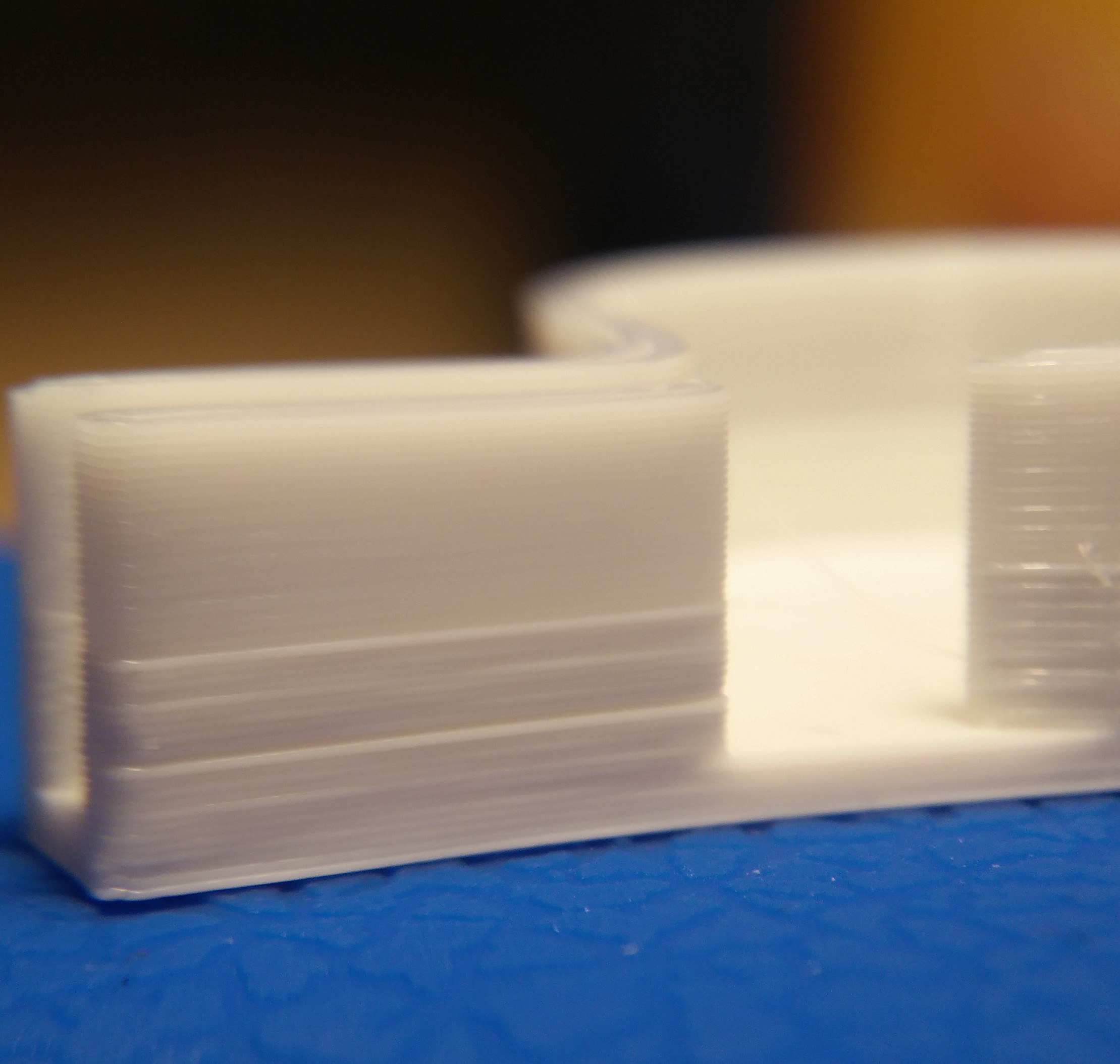
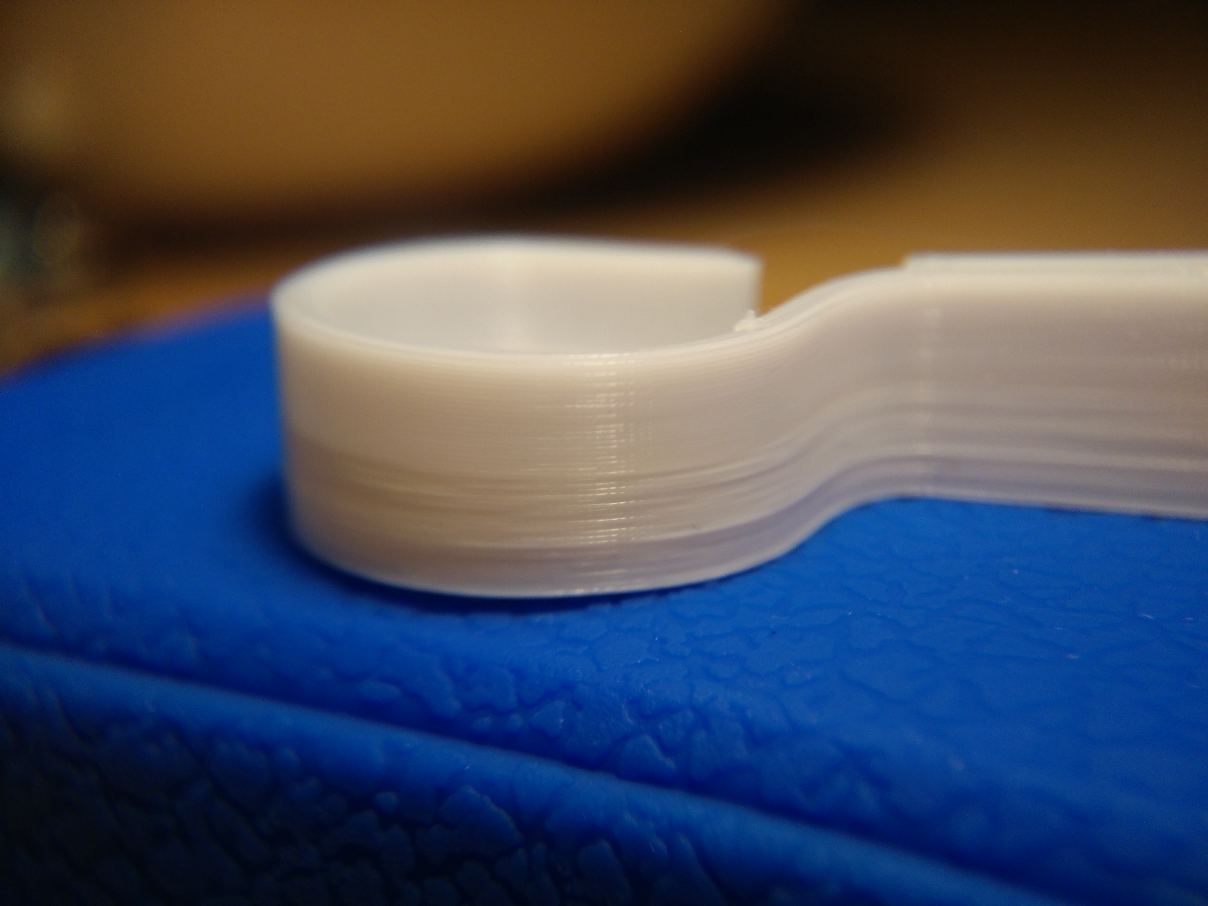
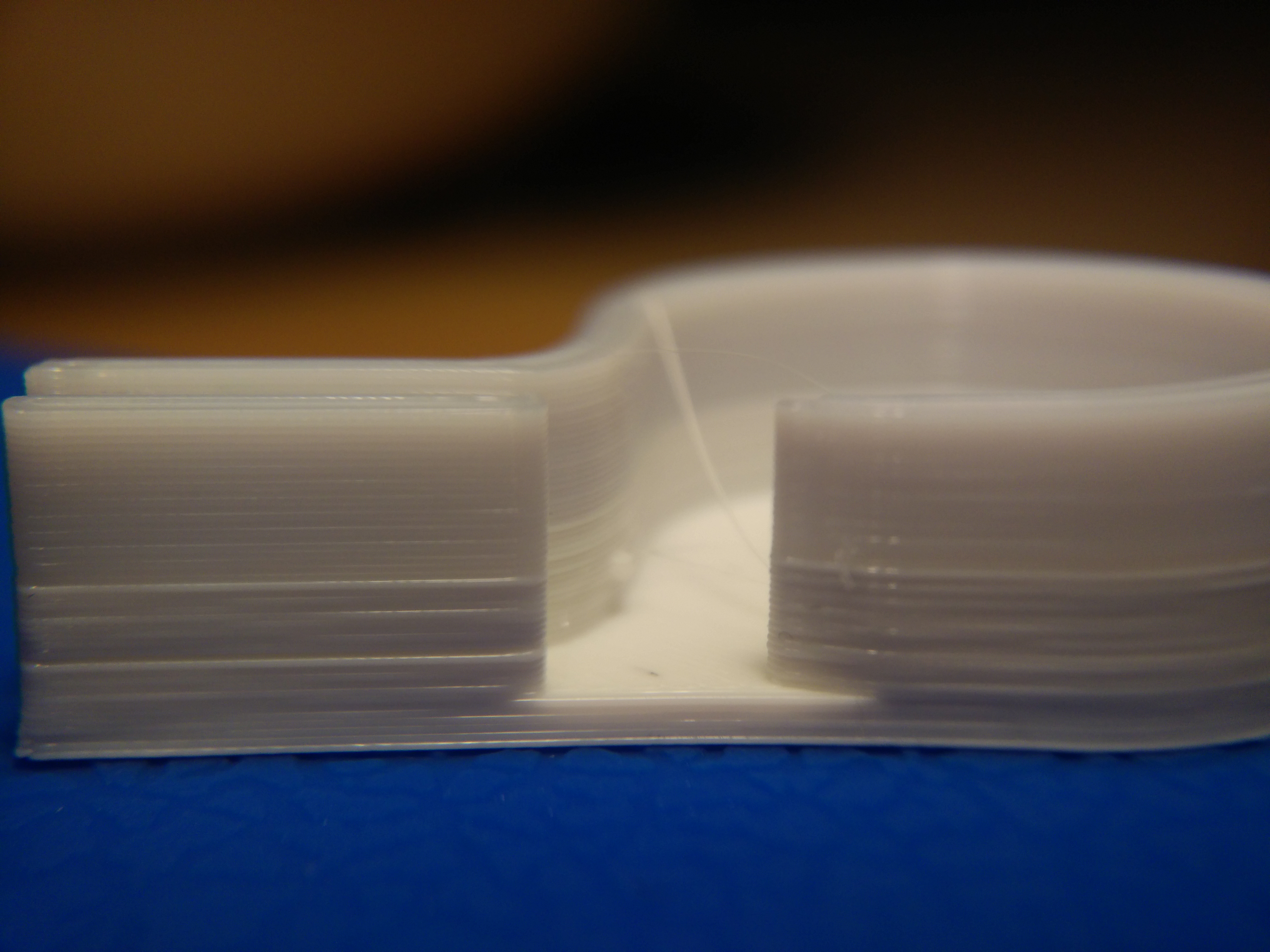
alientek
on 8 May 2018
@alientek In these images, I would be inclined to agree with @bubnikv regarding filament. Big bulges that are happening in specific areas of the print.
Sorry I can't give any tips, just wanted to point out that this is much different than the uniform sprinkling we're seeing of small bulges.
TheBrigandier
on 8 May 2018
@bubnikv I think we all understand how the filament can alter the extrusion width and it is to a point, unavoidable. This is not due to filament diameter variances. The surface of my prints are the same weather they are large or small and I personally have not see filament that varies in diameter in such a short distance to cause a 10mm cylinder print to be covered in "random" extrusion widths. An again, I can print the same model with the same filament on a monoprice select mini and the layers are consistent.
Skiidlive
on 8 May 2018
@alientek That top portion is better than anything ever off of my MK3 and dare I say better than the old monoprice as well. What happened?
Skiidlive
on 8 May 2018
@Skiidlive Nothing! its just a different white, some will say its more translucent. But it doesn't change the fact that the layers are clearly more uniform.
alientek
on 8 May 2018
@alientek
Based on your voronoi vase alone i can see irregularities in axis movement.
Perhaps this print's geometry is really bad, or Slic3r interprets it that way, but there is a pattern with wavy axis movement. Like a the extruder always wobbles from the front to the back, never stopping. This results in some layers where the layed down filament goes inwards, and the exact same spot above that on the next layer it goes outwards, i mean the filament on the layer above it flows into the direction where it has space.
This looks like cellulite. (yay, do we get to name this perhaps new print fault now?)
Also if you for the white prints; i've said a couple of times that white PLA prints absolutely horribly on most machines, perhaps you are lucky if you got a spool of white PLA and this one prints better than the other usual white PLAs. As @bubnikv said, the bowden acts as a buffer for printing, so this could very well be why the same spool of white PLA works on the CR10 and not the direct drive Prusa.
Could you perhaps test one thing? (this requires a bit of manual labor, but you guys are trying so much already)
Print a tall cube tower with 30x30x100 (0.20mm height, two perimeters, 4mm brim, no top/bottom/infill, also deactivate the "Enable Auto Cooling" from filament cooling settings and disable the "wipe while retracting" in the Extruder 1 settings) and change the filaments you have every 10mm.
Then you can see if some filaments print bad and some good.
Use this gcode in the "before layer change" in the printer settings: (this should be correct, but i'm typing from memory)
{if layer_z==10.0}M600{endif}
{if layer_z==20.0}M600{endif}
{if layer_z==30.0}M600{endif}
{if layer_z==40.0}M600{endif}
{if layer_z==50.0}M600{endif}
{if layer_z==60.0}M600{endif}
{if layer_z==70.0}M600{endif}
{if layer_z==80.0}M600{endif}
{if layer_z==90.0}M600{endif}
devilhunter84
on 8 May 2018
Hi ! I'm so happy to find this thread i'm fighting against this and i see i'm not alone ! Even girfriend which is not an expert saw that the quality of wall is not good. I sold my previous printer to buy thé mk3 and i have worst result on wall. I'm still using the same filament brand, I played with slic3r and S3D, jerk and acceleration, no real success. My previous printer used a bowden system with the same e3dv6 and MK8 extrudeur gear. I hope a solution will be found. I read above about test on ultimaker, I got one at work and there is absolutely not this problem with same filament brand, except that ultimaker use 2,85mm filament.
 eowindel
on 8 May 2018
eowindel
on 8 May 2018
An experiment that might prove useful would be to print two single wall cubes one immediately after the other using the exact same gcode for both. The important part of the experiment would be that between the two cubes the machine should not disable motors or heaters, re-home, or re-run mesh bed leveling. The first part should be removed very carefully so as not to disrupt any motor positions. Photographs should take care to position and orient the cubes to show lighting at precisely the same angle and distance.
The objective here is to see whether or not the artifacts are truly random/erratic. If the artifacts align with the computed absolute position of the motors the two cubes should have marked similarities in the artifacting and this would be stronger indication for a an error in the kinematics code's handling of floating point or similar type of problem. This is an easier test than examining step timing intervals for jitter which requires external test equipment; however if the cubes are not similar this is still a valid experiment.
johnlaur
on 9 May 2018
Any experts here care to explain how @alientek got that top half of his white whistle to print correctly? It does add additional confirmation that this has nothing to do with hardware.
Skiidlive
on 9 May 2018
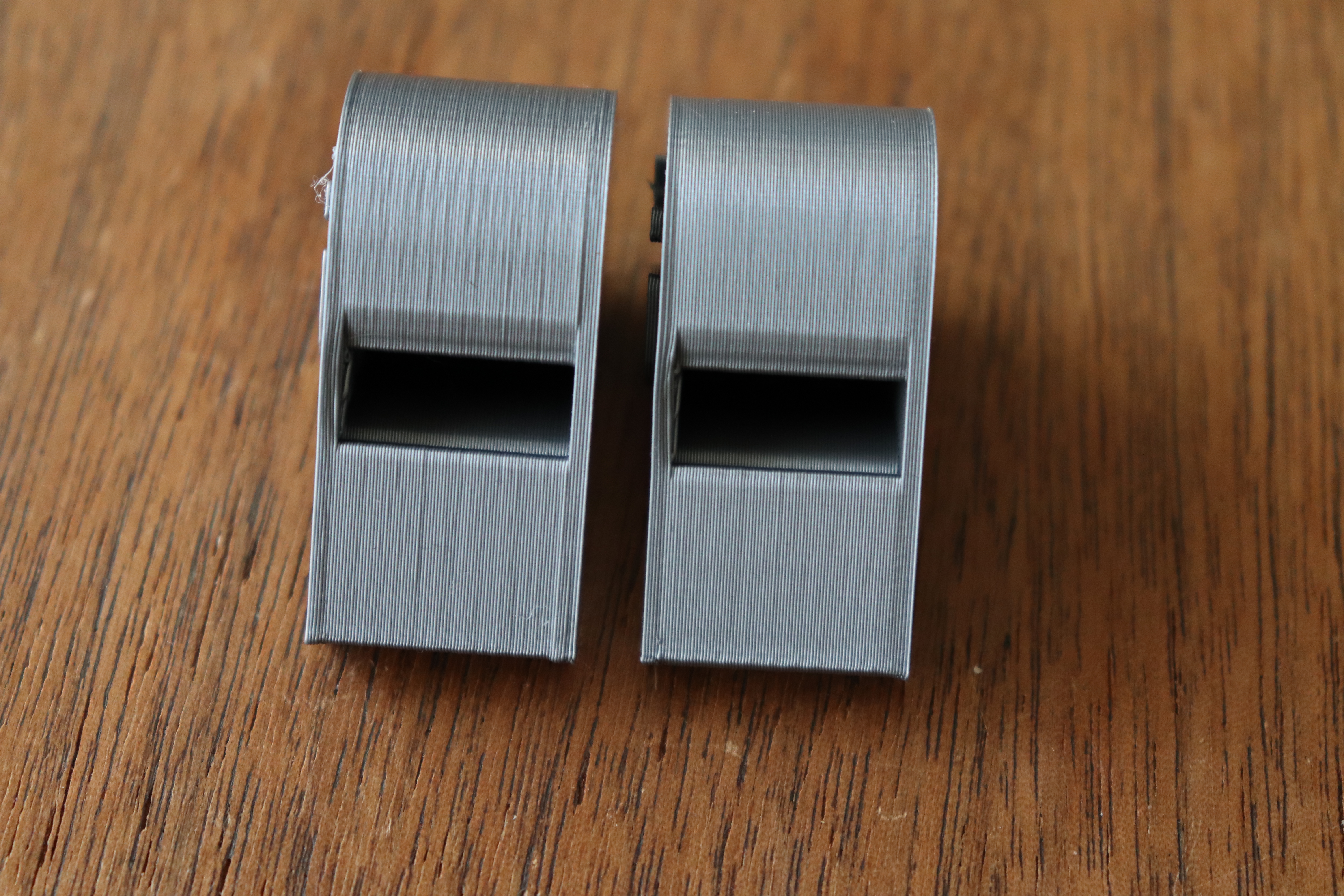
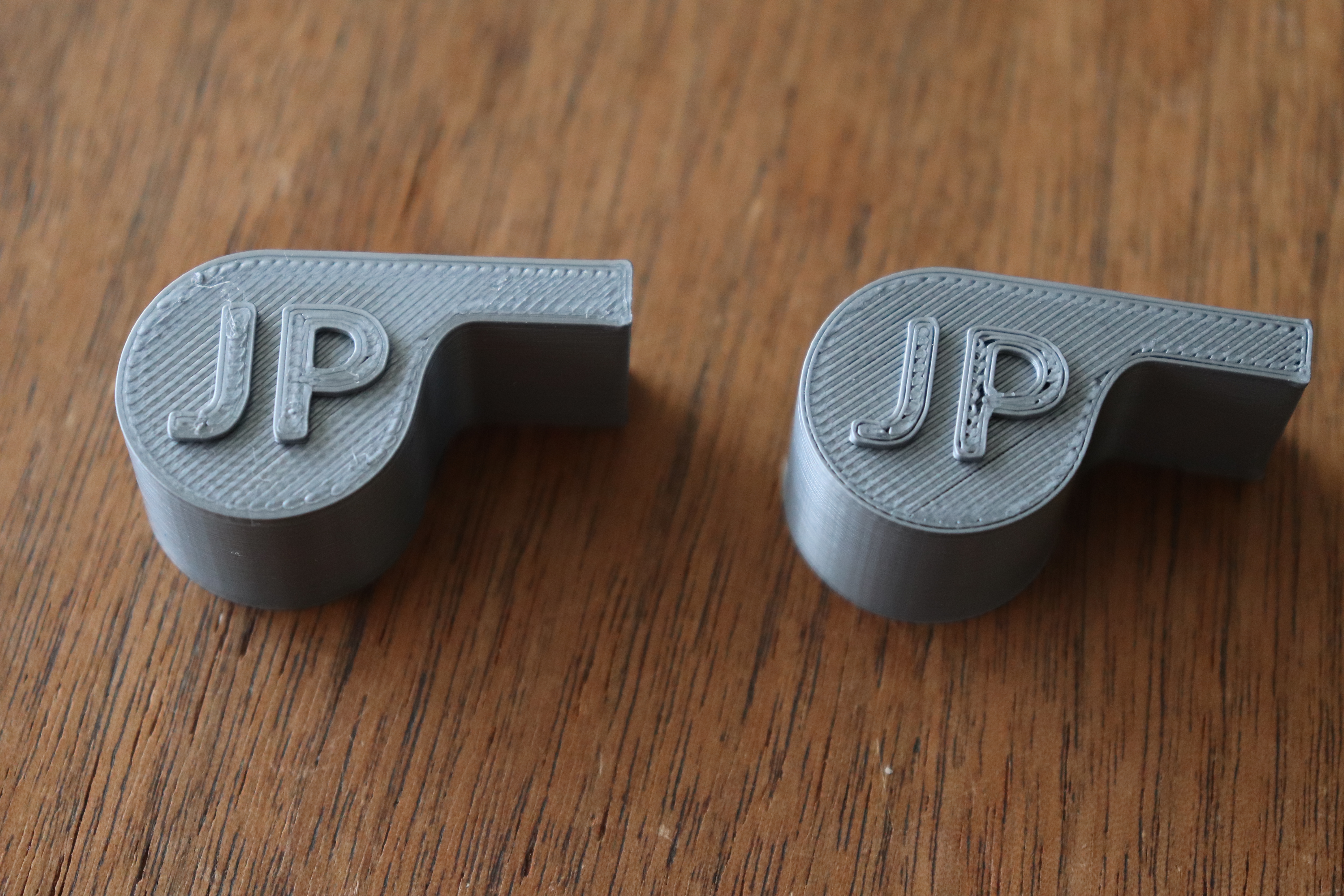
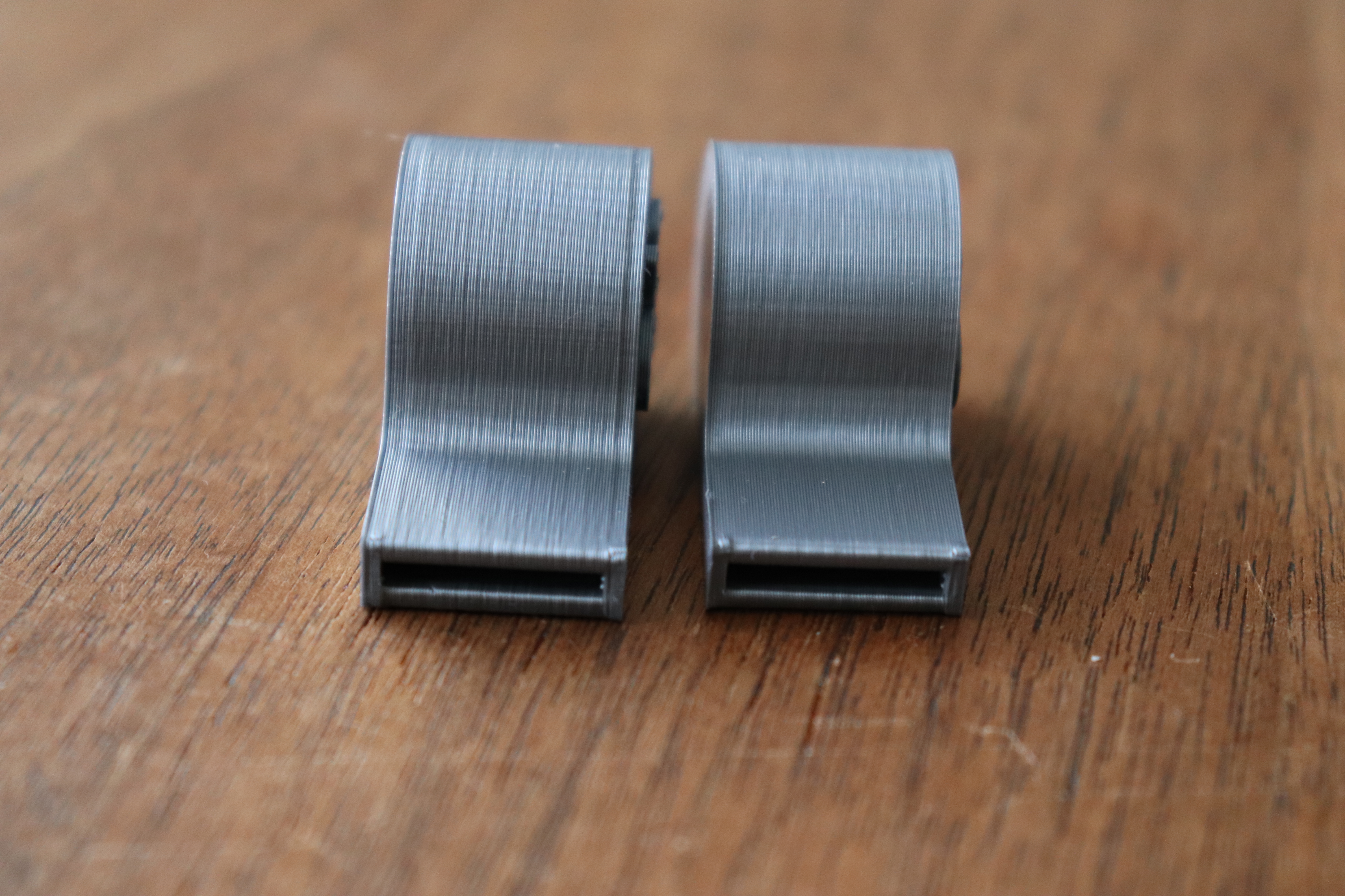
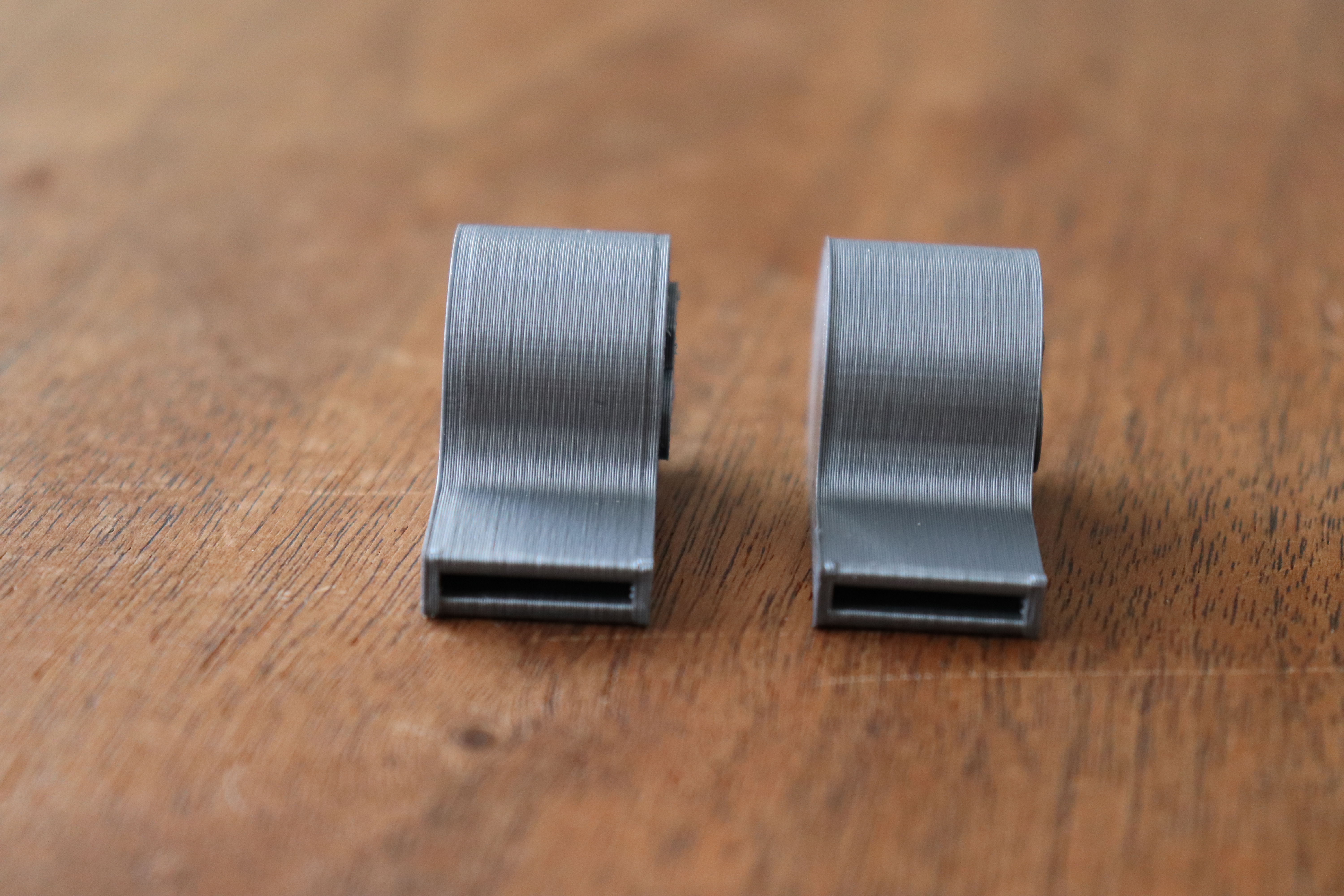
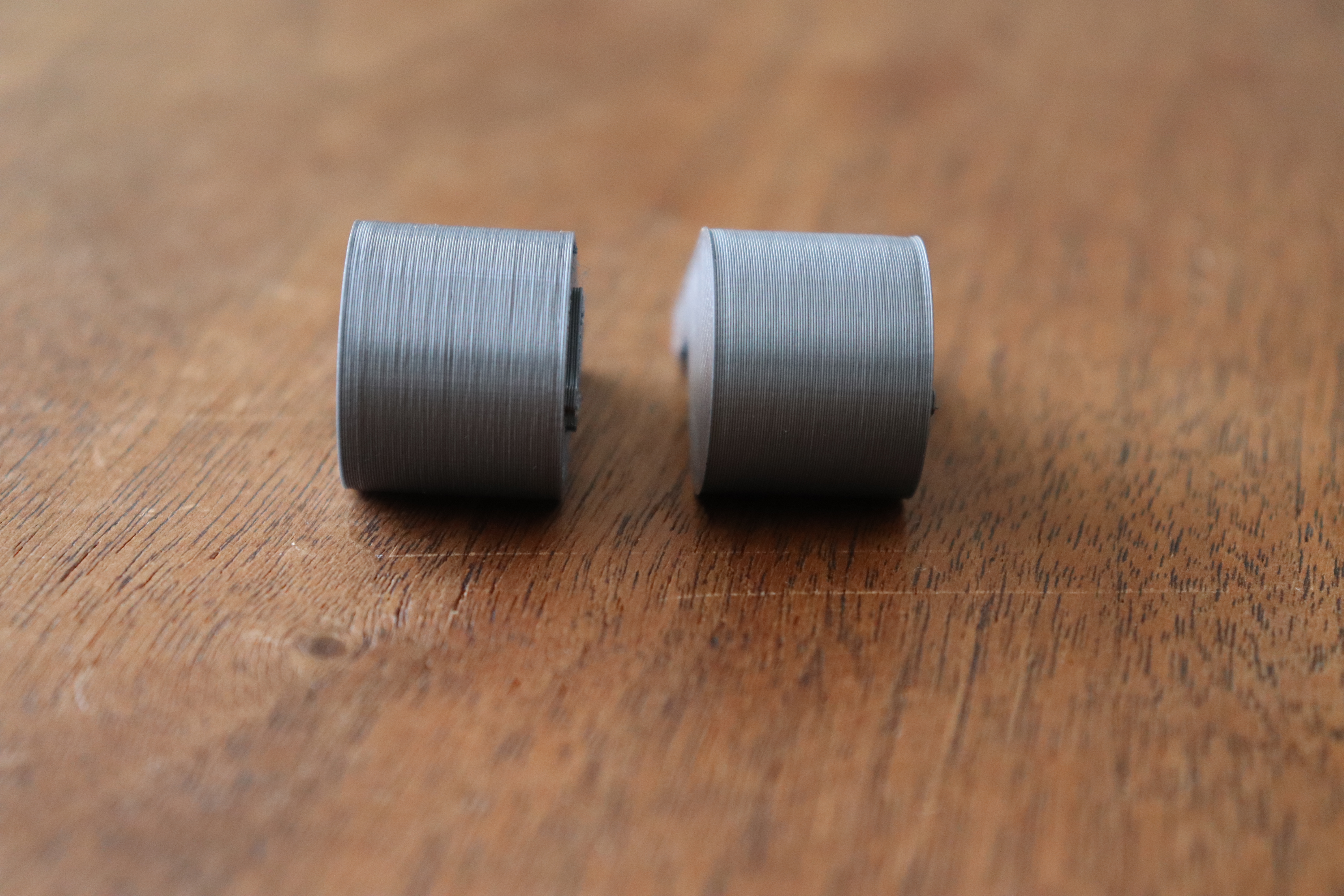
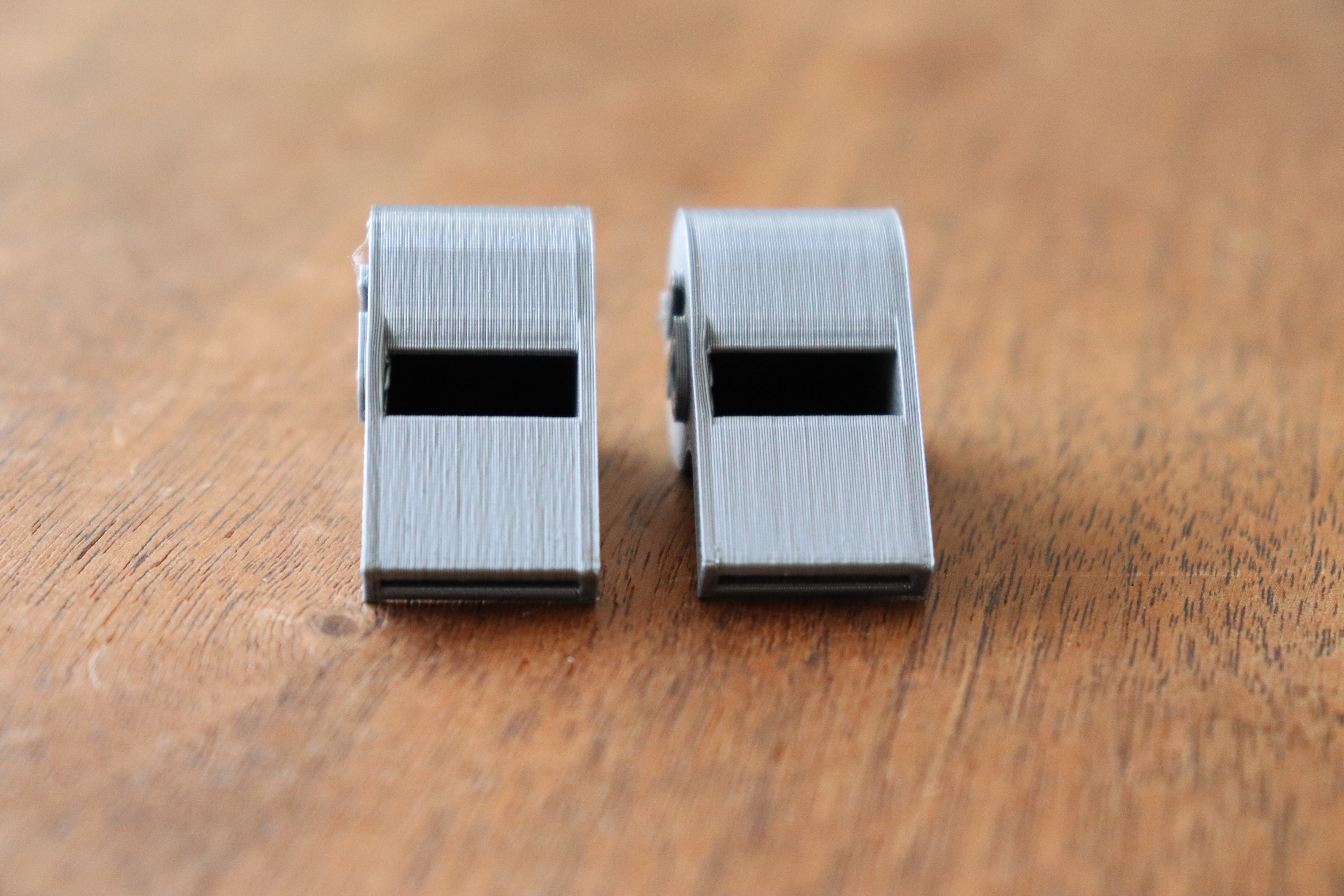
workinghard
on 9 May 2018
The Whistle gcode provided above. Left is MK3 3.1.3 Firmware, Right MK2S 3.1.0 Firmware. Same Prusa silver filament (same roll, printed MK3 first then MK2S). Looks to me like MK3 is overextruding, MK2S is under extruding
workinghard
on 9 May 2018
@workinghard The inconsistant extrusion issue was also on the mk2s, but i think the new gears on the mk3 made it more prominent.
alientek
on 9 May 2018
That's what it looks like at least, no wonder they cant't find anything wrong if they are comparing the software (MK3) to the old firmware (MK2).
alientek
on 9 May 2018
@alientek That's what it looks like at least, no wonder they cant't find anything wrong if they are comparing the software (MK3) to the old firmware (MK2).
I don't get it.
@alientek The inconsistant extrusion issue was also on the mk2s, but i think the new gears on the mk3 made it more prominent.
That is quite possible. That's the reason why I have built a hybrid MK2.5 with a MK2 print head. The results as of now are not conclusive, we may need to build more of these hybrids.
@workinghard
Thanks for the pictures. Such one to one MK2/MK3 tests are certainly convincing. We are looking into this issue diligently, we have a whole lot of hypotheses, which we will work through trying to pin point the main culprit.
bubnikv
on 9 May 2018
@johnlaur An experiment that might prove useful would be to print two single wall cubes one immediately after the other using the exact same gcode for both. The important part of the experiment would be that between the two cubes the machine should not disable motors or heaters, re-home, or re-run mesh bed leveling. The first part should be removed very carefully so as not to disrupt any motor positions. Photographs should take care to position and orient the cubes to show lighting at precisely the same angle and distance.
Thanks for the hint, we should do this experiment.
bubnikv
on 9 May 2018
@bubnikv I'm no expert but there is only 2 possibilities in my eyes..
1: Micro-stepping is not working as it should ( what happens if completely disabled or set to lowest value?)
2: The math for calculating E-steps example: instead of it extruding 2-4-6-8 its doing 2 - 4.1 - 6.4 - 8.7
alientek
on 9 May 2018
@alientek The firmware basically runs the good old Bresenham algorithm:
https://en.wikipedia.org/wiki/Bresenham%27s_line_algorithm
1: Micro-stepping is not working as it should ( what happens if completely disabled or set to lowest value?)
You may try that by modifying the open source firmware, but I expect the output to be considerably worse.
2: The math for calculating E-steps example: instead of it extruding 2-4-6-8 its doing 2 - 4.1 - 6.4 - 8.7
I doubt that, I bet the motor currents are correctly set according to the Bresenham line rasterization algorithm. What is for sure is, that the linearity of micro steps have never been guaranteed by the stepper motor specifications, and the main purpose of micro stepping is to lower audible noise.
bubnikv
on 9 May 2018
define TMC2130_USTEPS_E 32 // microstep resolution for E axis
When i change this line the extruder freaks out, what am i missing?
alientek
on 9 May 2018
@alientek Already been down this road way back in the issue, microstepping changes / completely disabled makes no difference.
Also your problem is coming from either a) not adjusting steps per mm to match your new microstepping value and/or b) you haven't done an m502+m500 so those new step values get applied and stored.
TheBrigandier
on 9 May 2018
@alientek Use M92 to set the steps-per-unit for extruder
Panayiotis-git
on 9 May 2018
@ff8jake Oh well no need to do it again i guess, well shit i don't know then.. Make a new algorithm?
@bubnikv
Just throwing ideas out here, is it possible to run the output of the Bresenham algorithm through another filtering algorithm to ensure perfect extrusion linearity?
alientek
on 9 May 2018
@alientek Did you reprint the whistle file to see if it printed complete as nice as the second half above?
Skiidlive
on 9 May 2018
@Skiidlive The white i have prints very nice, but it depends what color it is.. Best solution at this point is to let the R&D keep doing tests. @bubnikv Id come visit to help but i live in Denmark ¯ \ _ (ツ) _ / ¯
alientek
on 9 May 2018
Someone has tested smoother on the E ?
eowindel
on 9 May 2018
@bubnikv: Thanks for the comment. I just provided test results in case it's useful anyhow, not expecting or blaming anything. Feel free to provide a gcode if more testing is required.
workinghard
on 9 May 2018
@kursatu The update fixes what it claims to fix. Have you read this thread?
stahlfabrik
on 9 May 2018
Has this issue been determined to be hardware or software? I do not yet own a Prusa to try this but has anyone considered swapping out the board for a RAMPS/other? Should be able to wire it without fancy sensors easily enough.
My order of operations for diagnosing this would be reverting hardware changes to the last successful configuration (Bowden?) then swapping the board, only because an extruder change should be easier than tweaking marlin and a new board.
If belt, frame, rods and linear bearings are good quality this should be easy to diagnose.
 gplanon
on 11 May 2018
gplanon
on 11 May 2018
We just received one MK3 from a customer, which exhibits the uneven
extrusion discussed here. So we are poking around this printer and we are
trying to find the culprit. We should take our time though, as we shoud do
one change at a time and run a print or two before proceeding with another
change on the printer.
Our support initiated other exchanges. They are doing their best, though
they are in the process of transiting to a new information system, which is
not going quite smoothly, so please bear with us.
On Fri, May 11, 2018, 06:02 gplanon notifications@github.com wrote:
Has this issue been determined to be hardware or software? I do not yet
own a Prusa to try this but has anyone considered swapping out the board
for a RAMPS/other? Should be able to wire it without fancy sensors easily
enough.My order of operations for diagnosing this would be reverting hardware
changes to the last successful configuration (Bowden?) then swapping the
board, only because an extruder change should be easier than tweaking
marlin and a new board.If belt, frame, rods and linear bearings are good quality this should be
easy to diagnose.—
You are receiving this because you were mentioned.
Reply to this email directly, view it on GitHub
https://github.com/prusa3d/Prusa-Firmware/issues/602#issuecomment-388253296,
or mute the thread
https://github.com/notifications/unsubscribe-auth/AFj5I4fx05pabygLYEABgP6x2RiRC_-Fks5txQ05gaJpZM4TI5uR
.
bubnikv
on 11 May 2018
I think people are simply going to have to accept that the Mk3 - when it comes to quality - is not quite up to the standard of other comparable printers, even less expensive ones, even Prusa's own Mk2 beats the Mk3 when it comes to the quality of the prints . . . . that's not to say the Mk3 is not a great printer, it's a very good printer, with lots of features not found elsewhere at the same price, and the quality of prints is actually fairly reasonable, but it's just not quite in the same league as printers like the CR10 or AnyCubic i3 when it comes to the finish quality of a print.
 TynanTynan
on 11 May 2018
TynanTynan
on 11 May 2018
@TynanTynan CR10? My new $190 stock Ender 3 prints are better. Not hard to guess which one is Mk3 here, FW: 3.2.0 :D
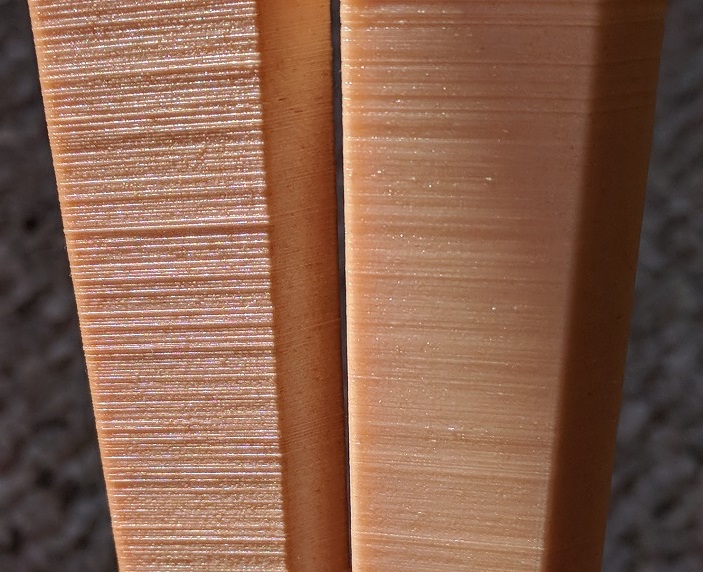
sneaky-tricky
on 11 May 2018
@sneaky-tricky
Yep! Exactly ! . . . I'm not saying that the Mk3 is a bad printer, in fact it's a very good printer in all sorts of ways, but if print quality is your goal then it's somewhat subpar, like you say it's very possible to get consistently better print quality out of a $190 printer, let alone a CR10.
I think the 3D printing community is slowly coming to the realisation that this is simply a part of the Mk3 and is not something that's going to be ironed out with a firmware update or new extruder . . . after so many months, and with the initial hype surrounding a new Prusa having died down, people from tech bloggers to Youtube reviewers are starting to mention the quality issues with the Mk3's print quality more and more . . . like I say I just think people will eventually need to accept the Mk3 for what it is, a great printer, but with a design that produces less than impressive surface quality . . . . I'd love for the Mk3 to match the quality of the Mk2 (or even one of the Creality machines), but maybe that's going to have to be something for the Mk4.
TynanTynan
on 11 May 2018
P.S. I can only assume that Prusa either did very little quality testing or none at all, maybe they assumed the quality would match the Mk2 due to similarities of the design, and failed to look closely enough at the real world prints the Mk3 was producing ? Who knows ?
I've yet to see a clean print - unmarred by the surface quality issues - even from Prusa themselves, check out the 'bundled 3D models' page on their website ( https://www.prusa3d.com/printable-3d-models/ ) . . . take a close look (click to zoom into the full res image) at the various example like the silver whistle and the planetary gear, they all display the issue.
TynanTynan
on 11 May 2018
One of Prusa's own efforts . . . .
TynanTynan
on 11 May 2018
Did anyone here tried Settings >> E-Correct in Slic3r? It does requires new firmware 3.2.0 and the latest Slic3r.
Read these two:
 jonnieZG
on 11 May 2018
jonnieZG
on 11 May 2018
@jonnieZG Yes, I printed tower and noticed no difference in extrusion. Moire frequency is changing with e-correction but extrusion is the same.
sneaky-tricky
on 11 May 2018
@TynanTynan The fact that the 2.5 also exhibits the same extrusion issue shows that its not limited to the MK3. Hopefully the culprit can be sorted now Prusa has a faulty machine to tear apart and diagnose.
A random question but does anyone here with the issue use an e3D silicone sock? Just wondering if it was a PID issue or something as I did notice that my MK3 fluctuates alot even after tuning compared to my MK2 which is pretty stable.
 slayer1551
on 11 May 2018
slayer1551
on 11 May 2018
A random question but does anyone here with the issue use an e3D silicone sock?
@slayer1551 I use an e3D silicone sock, doesn't make the slightest difference to this issue. Didn't really get temperature fluctuations before using the sock either.
cjo20
on 11 May 2018
@cjo20 Ah ok thanks :( , have my 2.5 arriving soon but until this can get fixed I think I'll hold off.
Like others have said I love the MK3 overall with the new bed and how quiet it is but the quality just isnt as good.
slayer1551
on 11 May 2018
So I had a strange idea.
Is it possible that this is all due to the e3d being slightly loose or having some give?
It always bothered me that the e3d is not mounted directly in any way and is only held in place by being squeezed by 3d printed parts. This leads me to suspect that it allows for a small amount of flex, especially since that parts holding it are printed with petg.
The best comparison shot we have on here is with a cr10s which has a more solidly mounted hotend https://www.en3dstudios.com/wp-content/uploads/2017/05/CR10_HOTEND02.jpg
And for that matter isn't it possible that this whole issue is at least partially due to the extruder body being 3d printed?
Obviously this wouldn't explain the difference in quality between the mk3 and mk2, but frankly I'm not convinced that this is a problem unique to the mk3. There haven't really been any good comparison shots between the two demonstrating this change in quality.
 JaseWorthing
on 11 May 2018
JaseWorthing
on 11 May 2018
@JaseWorthing The larger gears on the MK3 made the issue more prominent. The issue is also effecting the mk2 but because the gears are smaller they act as a filter reducing the artifact.
alientek
on 11 May 2018
@JaseWorthing Well my MK2 is still printed in ABS but if the MK2 now comes with parts printed in PETG that shouldnt be an issue. I did notice the whole extruder did have more wiggle than the MK2
slayer1551
on 11 May 2018
@JaseWorthing Further up this thread I posted a side-by-side picture of a print from my MK3 and a print from my MK2 (not MK2S). Both exhibit the same issue. No one involved in this thread acknowledged that post but I thought it very interesting that the issue can be traced back to the MK2. We're talking about two very different machines both exhibiting the same issue.
So, yes, the problem isn't unique to the MK3.
rcfsguy
on 11 May 2018
@alientek
The larger gears on the MK3 made the issue more prominent. The issue is also effecting the mk2 but because the gears are smaller they act as a filter reducing the artifact.
Is it possible the filament is traveling to one side and then snapping back in the gear causing the issue?
mvasilakis
on 11 May 2018
@bubnikv This isn’t an issue with just “some” mk3s. Most have the issue. In fact if you took 90% of peoples prints, put them in downlighting, all would exhibit the behavior. If you don’t focus on a broad fix, then you’re going to have a lot of people still with the issue.
 ctilley83
on 11 May 2018
ctilley83
on 11 May 2018
@rcfsguy That's actually very concerning. The fact that nearly everyone here seems convinced that this is an issue that the mk2 didn't have is not helping us zero in on the cause.
In fact, I feel like the lack of comparison shots is a huge problem here. I may have missed some, but to my knowledge, this whole thread only has two comparison shots that compare the mk3 to another printer that doesn't have the issue.
I'd be very curious to see more examples of prints without the issue and what printers they came from.
JaseWorthing
on 11 May 2018
@slayer1551
“The fact that the 2.5 also exhibits the same extrusion issue shows that its not limited to the MK3. Hopefully the culprit can be sorted now Prusa has a faulty machine to tear apart and diagnose”
As a Mk3 owner I really hope they can find a way to resolve the issue too, but after so many months and with Prusa themselves not even knowing what’s causing the issue (let alone being on the way to resolving it) we might simply have to accept the Mk3 for what it is, an improvement in many departments, but a downgrade in print quality. This wouldn’t be the first time a company has taken a step backwards, for example the 🔥 Galaxy Note 7 🔥 . . . which I also owned, lol : )
I also think the time frame plays a role here, Mk2 early 2016 - Mk2S early 2017 - Mk3 late 2017 . . . how long do they play around with the issue before calling it a day and moving onto the Mk4 ?
Anyhow, I’m not adding anything particularly constructive here, just putting the idea out there that we might have to accept the Mk3 for what it is, the ugly cousin we keep in the attic.
TynanTynan
on 11 May 2018
@ctilley83
"This isn’t an issue with just “some” mk3s. Most have the issue."
Agreed, I've yet to see a 'clean' print come off the Mk3, even Prusa themselves have not managed to produce a decent quality print (one without the surface quality issues) - see my post above that links to an image of Prusa's own 'planetary gears' print on their 'bundled prints' page, the rest of the prints on the page display the same issue.
I suspect users fall into two broadly defined groups, those with the issue and those who have the issue but aren't overly bothered by it (or have not even noticed it) . . . but like you say, and from everything I've seen and read, the issue effects all Mk3s rather than 'some'.
I'd be happy to be proven wrong, all Prusa need do is print some issue free test cubes and share them here.
TynanTynan
on 11 May 2018
I would be really curious to see how a geared stepper or maybe a Wade's performs vs this. Seems to me going 1:1 to something like 5:1 may show obviously effects if it's being caused by the stepper?
TheBrigandier
on 11 May 2018
My MK3 has experienced pretty much every other problem out there, so I totally feel your frustration and I'm not trying to discount anyone's claims, but I honestly think my MK3 is NOT experiencing this extrusion issue. I hate to contribute any misinformation to this thread so please look at my prints and tell me if I'm wrong. Here are my results for the "linearity calibration tower" gcode ( https://github.com/prusa3d/Prusa-Firmware/wiki/Extruder-linearity-correction-calibration ). Please zoom in on the 2nd or 3rd section from the bottom (and ignore the moire in the other sections). I'm not seeing inconsistent extrusion like what is described in this thread. If this particular gcode is not a good test, I'll try others, but I don't think I'm seeing this in any of my other prints either.
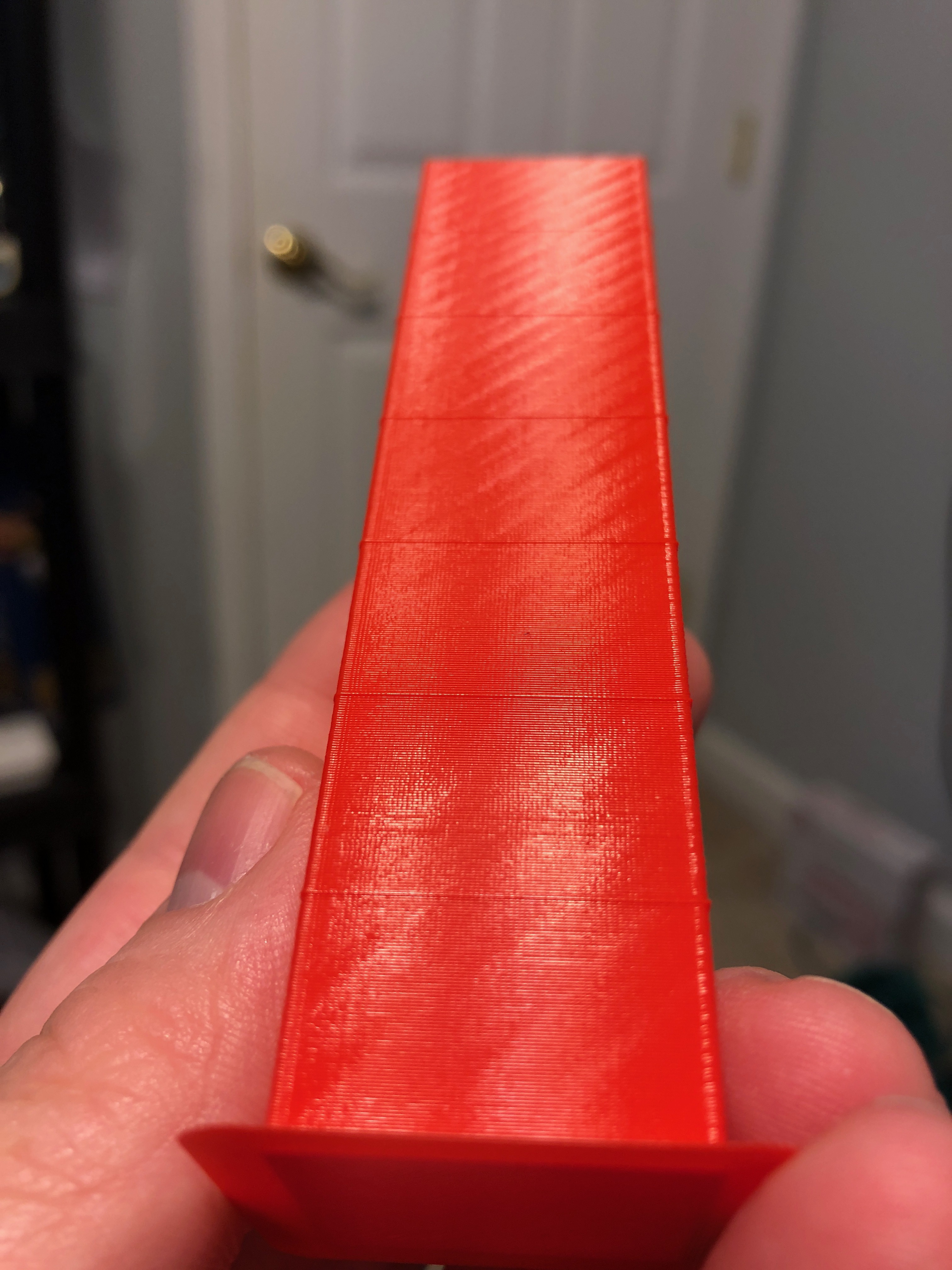
HOWEVER, my MK3 is not 100% stock:
1) I'm using Z-axis parts designed by jltx ( https://www.thingiverse.com/thing:2779123 ). If this is what solved the problem, then the issue could be caused by Z-axis alignment issues.
2) I'm using a modded version of the R2 X-axis idler end part. My problem was the M3 screw for the X idler pulley was getting pulled slightly out of square, so the pulley would twist and squeak and the X belt was riding on the edge of the idler and getting ground up into dust. I reduced the tolerance of the hole for the pulley M3 screw by about 0.1 or 0.2mm if I remember correctly. Now the pulley sits flush on the screw, and the belt is no longer twisting and wearing down. BUT if this was the main issue causing inconsistent extrusion for some, it would only affect the X-axis surfaces.
3) I'm using custom Y-axis rod holders plus shims to get my bed almost perfectly flat, which reduces the amount of Z-axis movement needed for MBL. But, if MBL were the main cause of the problem, then disabling MBL should fix it. (I think that's been tried and rejected.)
jettoblack
on 11 May 2018
@jettoblack Looks good but can you print a cube in a grey color, and use indirect light? like a flashlight
alientek
on 11 May 2018
@jettoblack you need to photograph in downlighting so you can see the issue. Head on light doesn’t show it.
ctilley83
on 11 May 2018
@jettoblack Take a look at the corners. I think I see that the corners are a bit erratic, which the inconsistent extrusion issue will act as a contributing factor. And I agree with the others - unless you use a direct light source from above the print at the correct angle of deflection you won't notice the issue.
rcfsguy
on 11 May 2018
@TynanTynan FWIW, my MK2 kit was shipped December 2016. My MK3 kit was shipped December 2017.
rcfsguy
on 11 May 2018
Regarding this issue occurring on the MK2: My MK2 has exhibited this
symptom last week, after someone reassembled my extruder. I’ve managed to
trace the issue to a missing screw which should’ve secured the hotend in
place. After re-adding this screw I got rid of this issue.
Perhaps the new extruder design (which, correct me if I’m wrong, is a
common link between the mk2.5 and the mk3) allows for more hotend wobble,
and that’s what we’re seeing here?
On Fri, 11 May 2018 at 23:32 Tim Gleason notifications@github.com wrote:
@TynanTynan https://github.com/TynanTynan FWIW, my MK2 kit was shipped
December 2016. My MK3 kit was shipped December 2017.—
You are receiving this because you were mentioned.
Reply to this email directly, view it on GitHub
https://github.com/prusa3d/Prusa-Firmware/issues/602#issuecomment-388477902,
or mute the thread
https://github.com/notifications/unsubscribe-auth/ABPL7JLfqm01qR3jcNgmL_hEQ4wspH0Oks5txfVegaJpZM4TI5uR
.
MoshiBin
on 11 May 2018
@rcfsguy
“FWIW, my MK2 kit was shipped December 2016. My MK3 kit was shipped December 2017.“
Not sure what point you are making here ?
TynanTynan
on 11 May 2018
@ff8jake
I would be really curious to see how a geared stepper or maybe a Wade's performs vs this. Seems to me going 1:1 to something like 5:1 may show obviously effects if it's being caused by the stepper?
I don't know if it's still relevant to this question, but i finished one of my custom MK3 clones with the E3D Titans, aka 3:1 geared stepper.
I've printed the linearity correction gcode tower after calibrating the machine, and this is the result:
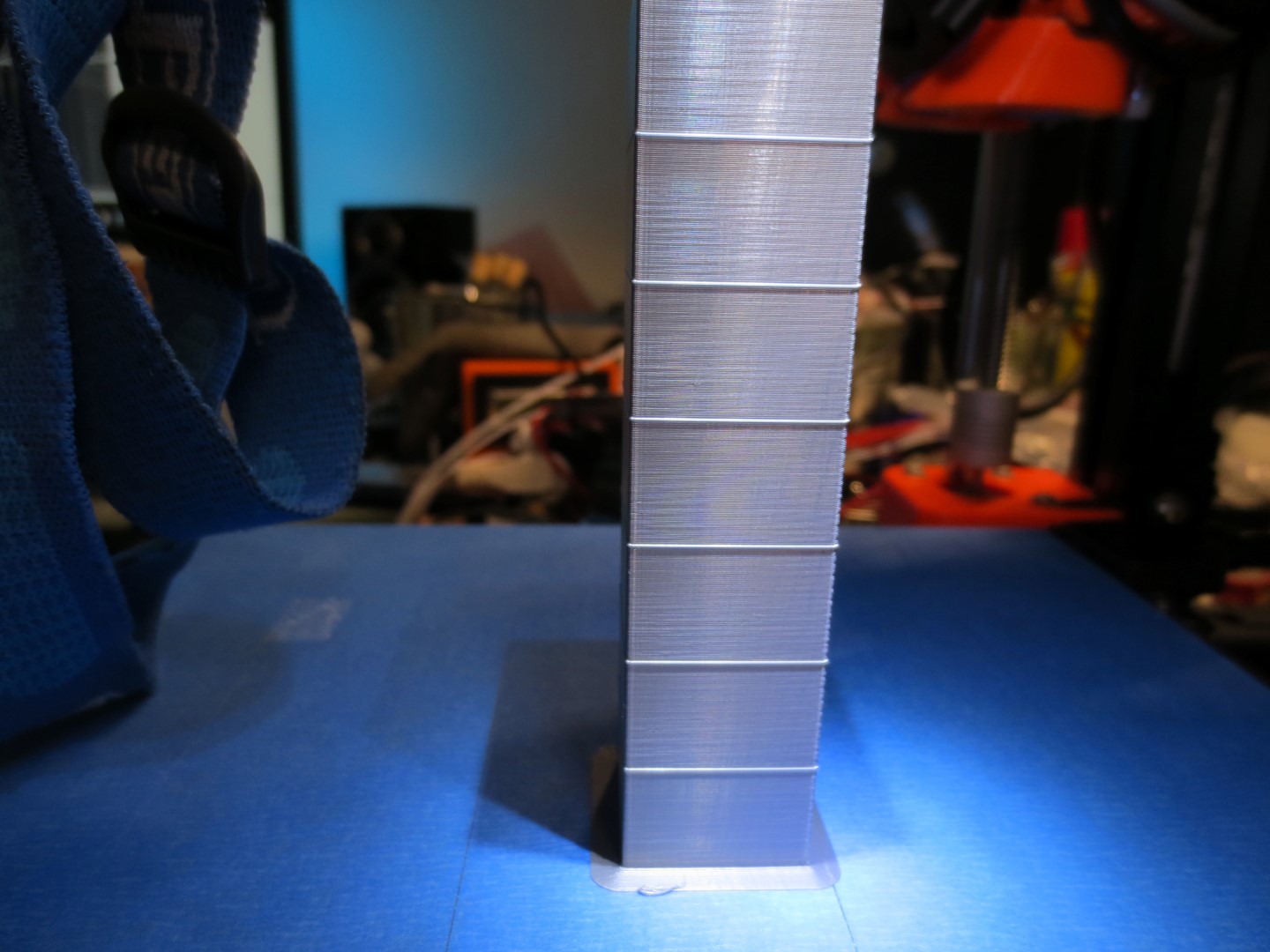
Album here:
https://imgur.com/a/Vcw0h66
I cannot see any moire effect at all on any of the sections, and all sections of the tower look _absolutely_ the same.
Remember i have 1626 Esteps on the Titan vs the MK3's 280 Bondtech Esteps, so perhaps more steps are masking the moire issue.
I do notice some very very faint pattern that shows across all sections, it's like this:
     //    //
   //    //
 //    //
No amount of linearity tweaking will get rid of it, and it's very hard to see and almost impossible for the camera to pick up (but i managed to get it in the pic). It does not show itself on normal prints however.
I still have the random fat layers that you all have, too.
Last pic is some kind of Z banding that only affects the X axis that is only visible via the light 45" from above method, i don't know where this comes from. It wasn't there two weeks ago during the first test prints. Perhaps the second machine will or won't show this, i'm still building the last bits of it.
devilhunter84
on 11 May 2018
And I agree with the others - unless you use a direct light source from above the print at the correct angle of deflection you won't notice the issue.
@rcfsguy Or a lithophane which shines light through the print. That's my main concern, not the surface quality of opaque parts, though I haven't yet tried to sell a print off of this printer. I don't rightly know if customers would accept the surface quality. They already tend to have pretty high expectations, not being educated about the platform.
Lithophanes off this machine so far have all gone in the junk bin.
MarcusAdams
on 11 May 2018
I don't agree that this is not a problem unless direct light source from above, the surface is much more uneven and not as glossy as compared to eg. CR-10 as you can see in these images.
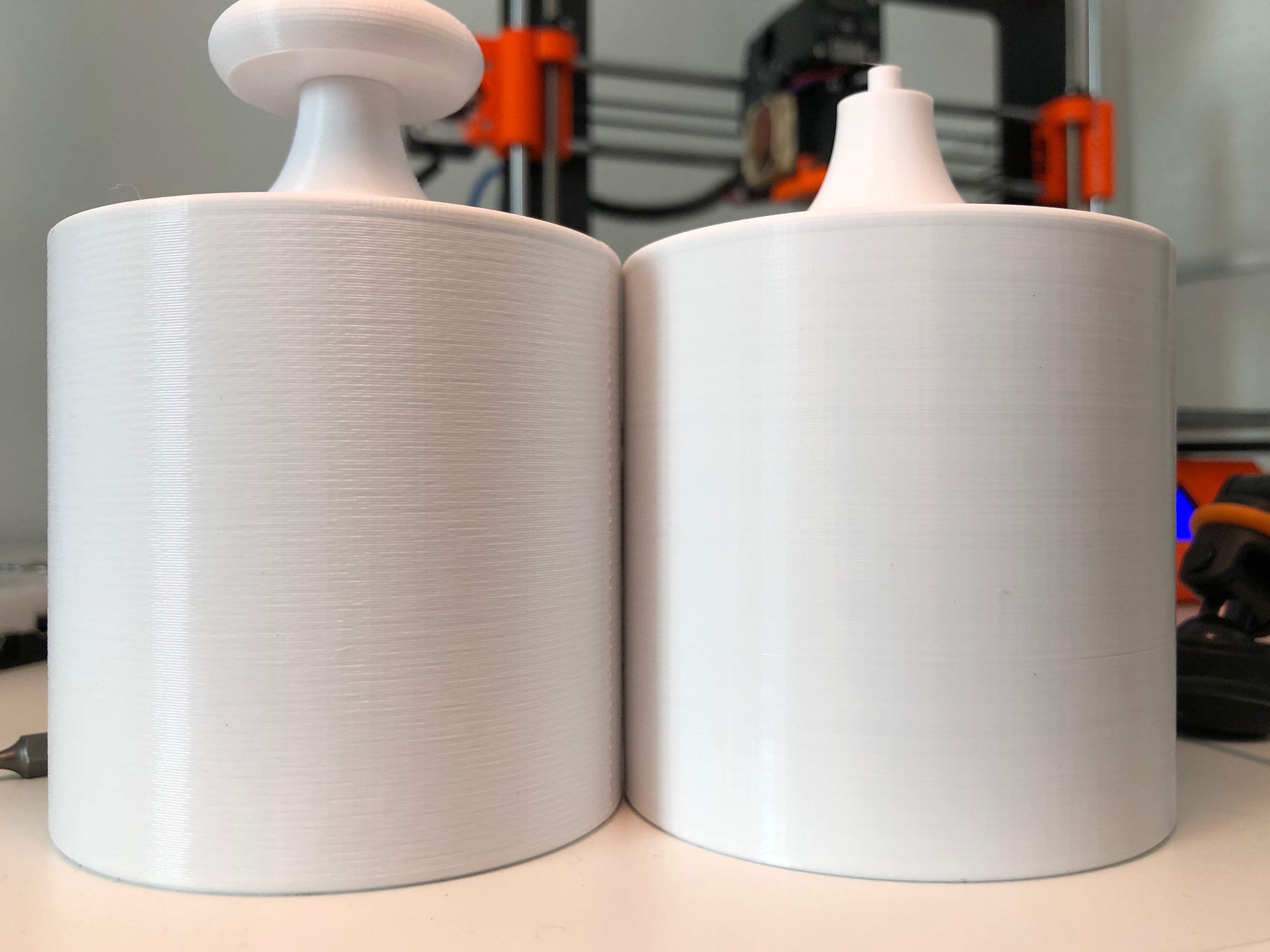
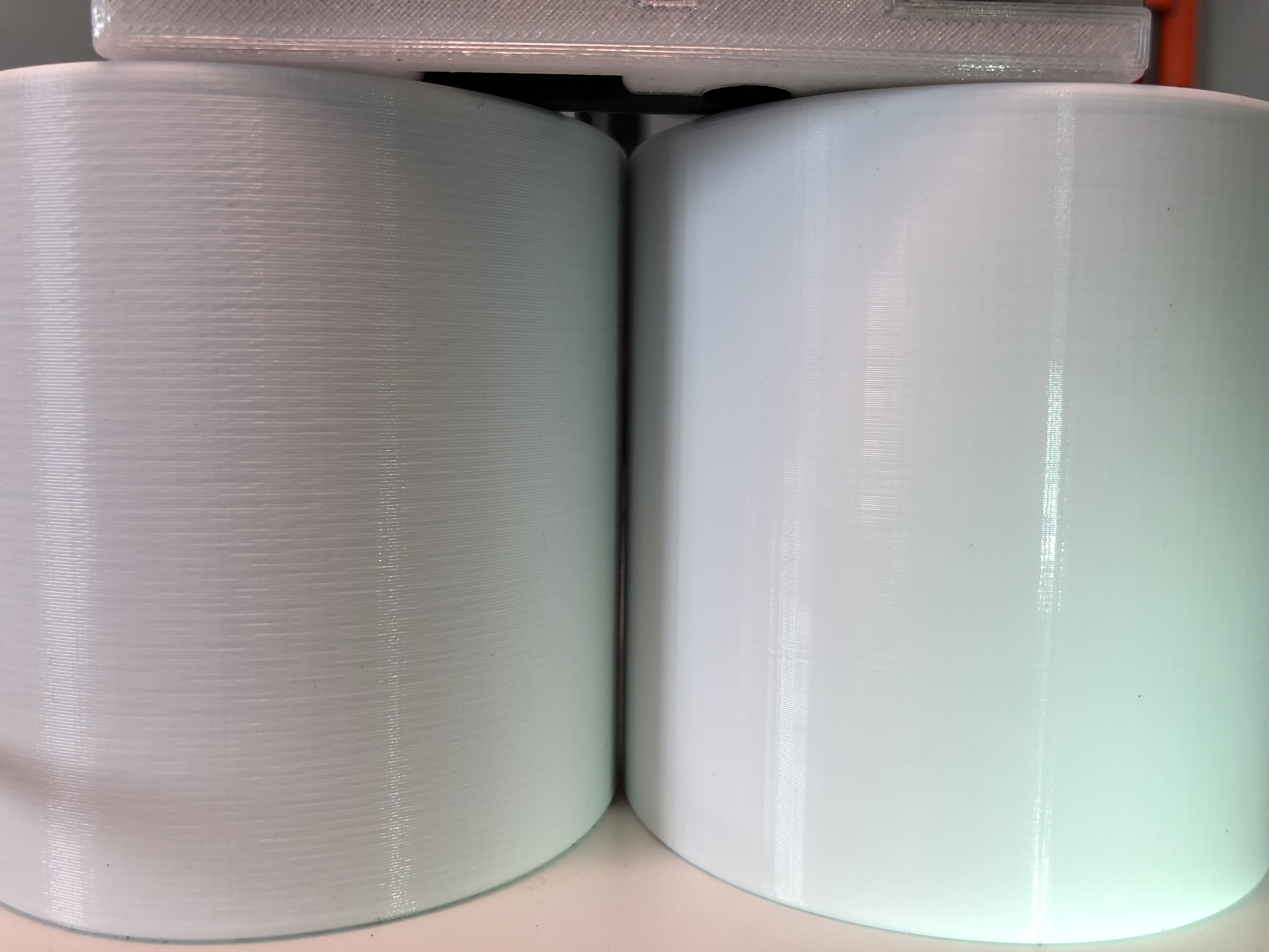
 vinjegaard
on 11 May 2018
vinjegaard
on 11 May 2018
@vinjegaard: I think it's not useful to compare Direct Drive vs Bowden setup. There are, is and will be difference in print quality. Better comparison will be to other direct drive extruder with TMC2130 driver.
workinghard
on 11 May 2018
@devilhunter I think those lines you see ARE the moire? Adjust your flow up/down a percentage or two and you'll see it change angle. If it does, I can confirm the linearity correction affects that in stock mk3 configuration. That looks just like the moire I have.
The sad part is E-Correct doesn't get rid of it completely, but it helps.
Just got home and about to try the calibration myself. Wish me luck.
@workinghard Earlier in this issue someone tried with a bowden setup and got same erratic results; however, if they were wrong and bowden gets this boost (not to mention much lighter extruder assembly by far!), I'm about to join team Bowden and kiss flex filament goodbye.
TheBrigandier
on 11 May 2018
@vinjegaard
I don't agree that this is not a problem unless direct light source from above, the surface is much more uneven and not as glossy as compared to eg. CR-10 as you can see in these images.
That's not an entirely fair comparison as the Mk3's layer height looks to be around half that of the CR10's (that is to say the CR10 is printing at ~twice the vertical resolution) . . . but I have to say the CR10 print does look a lot better than anything I've seen come out of a Mk3 . . . what's more telling is that people don't even need to point out which print is which now 😅 just stick a print from a CR10 or an AnyCubic or even a lowly Cetus next to a Mk3 print and unfortunately people are able to pick out the Mk3 print simply by its marred surface quality.
TynanTynan
on 12 May 2018
@workinghard You're sort of right it may not be fair to compare with CR-10 but I placed the model there to illustrate that it's still a problem even if a light source is not directly above. See the image below for a side-by-side comparison with a model printed on my old I3 clone direct drive. Once again no harsh light from above. @TynanTynan All models are printed with .2 mm layer height (except for that fillet and top part on the cylinder that is .12 mm).
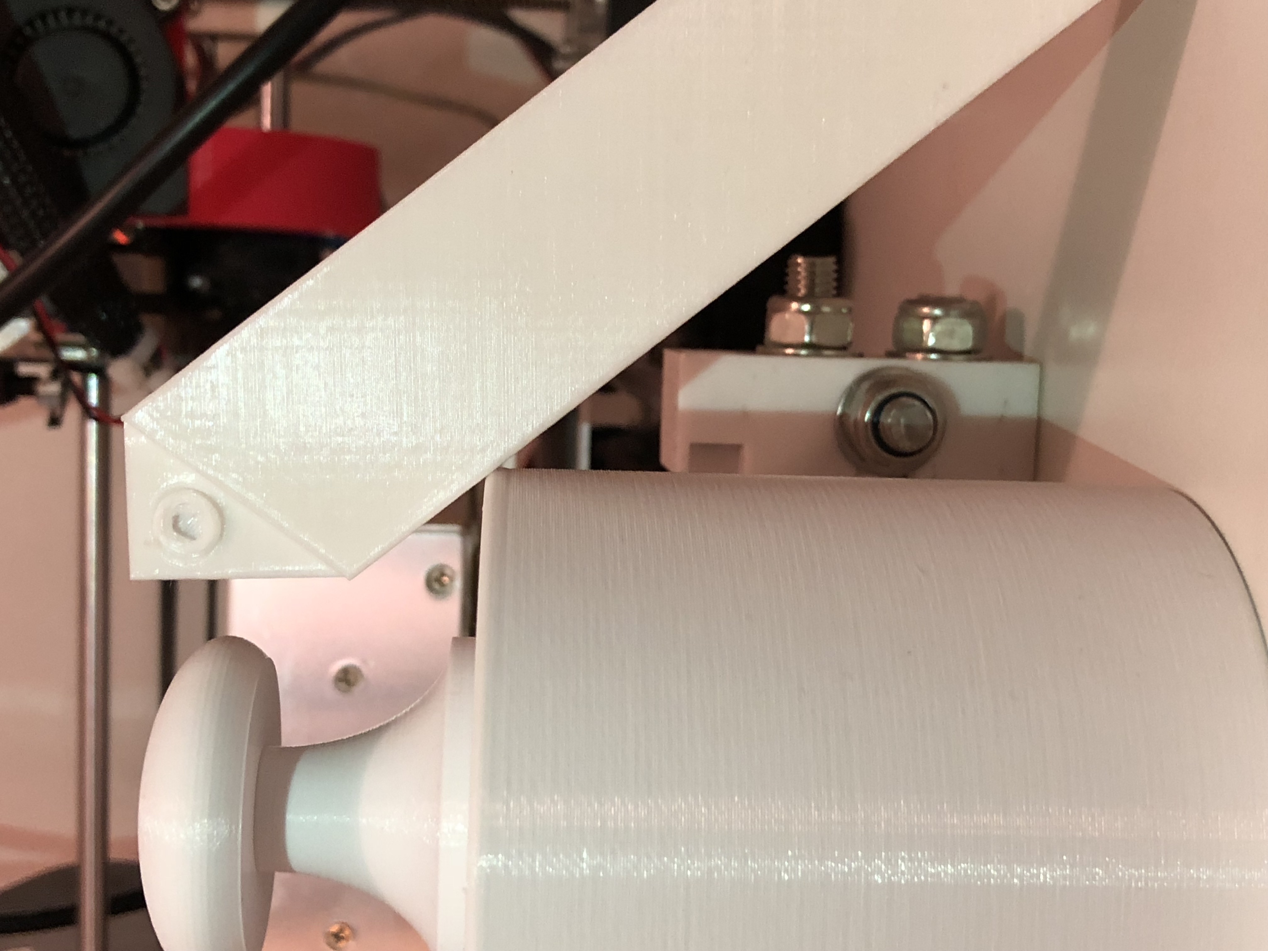
vinjegaard
on 12 May 2018
@vinjegaard The light shining down from above thing is my fault. Most people are blind and don't see what we're talking about, and it was an easy way to exaggerate the effect. You're 100% right, once you see it, every MK3 print shows this fuglyness in general.
TheBrigandier
on 12 May 2018
@vinjegaard
All models are printed with .2 mm layer height.
Setting a levels threshold (+ desaturating) to show the individual layers (on the main body of the print) shows the print on the right (the CR10) to be much finer in layer height.

TynanTynan
on 12 May 2018
@bubnikv Is it possible to get the same gear size as the MK2S just bondtech style? If everything else fails the old gearing will help mask the issue.
alientek
on 12 May 2018
@TynanTynan I can only say that the body of both CR-10 and MK3 cylinders are sliced in S3D with .2 mm layer height. The diagonal model is also printed with .2 mm layer height on an I3 clone. There might be additional parameters that differ between the printers. I posted the images simply to show that MK3 results are bad even with more flattering lighting conditions as a response to @rcfsguy
unless you use a direct light source from above the print at the correct angle of deflection you won't notice the issue.
There should be no discussion as to if this is an issue or not depending on lighting, it is a real issue.
vinjegaard
on 12 May 2018
@vinjegaard
I can only say that the body of both CR-10 and MK3 cylinders are sliced in S3D with .2 mm layer height.
A mistake must have slipped in somewhere in the process, the layer heights on the print are clearly different, but like you say this still illustrates the fact that the poor finish of the Mk3's print quality shows up in normal lighting situations (and not just light hitting the print at shallow angles),
TynanTynan
on 12 May 2018
I am looking forward to this thread getting back to ideas on how to solve the problem, instead of trying to say there is no problem. The quality is inferior to what it should be.
The idea of the “loose hotend” is intriguing to me - it is a definite difference between the MK2 and MK3, and so we should pursue it
Dioblieum
on 12 May 2018
@TynanTynan I concede defeat after checking the factory file for the MK3 print as it is clearly .32 mm layer height xD
.2 or not the layers still look like crap and should be even more visibly even with .32 ^^
Here's a calibration print and this time I guarantee .2 mm with visible uneven layers.
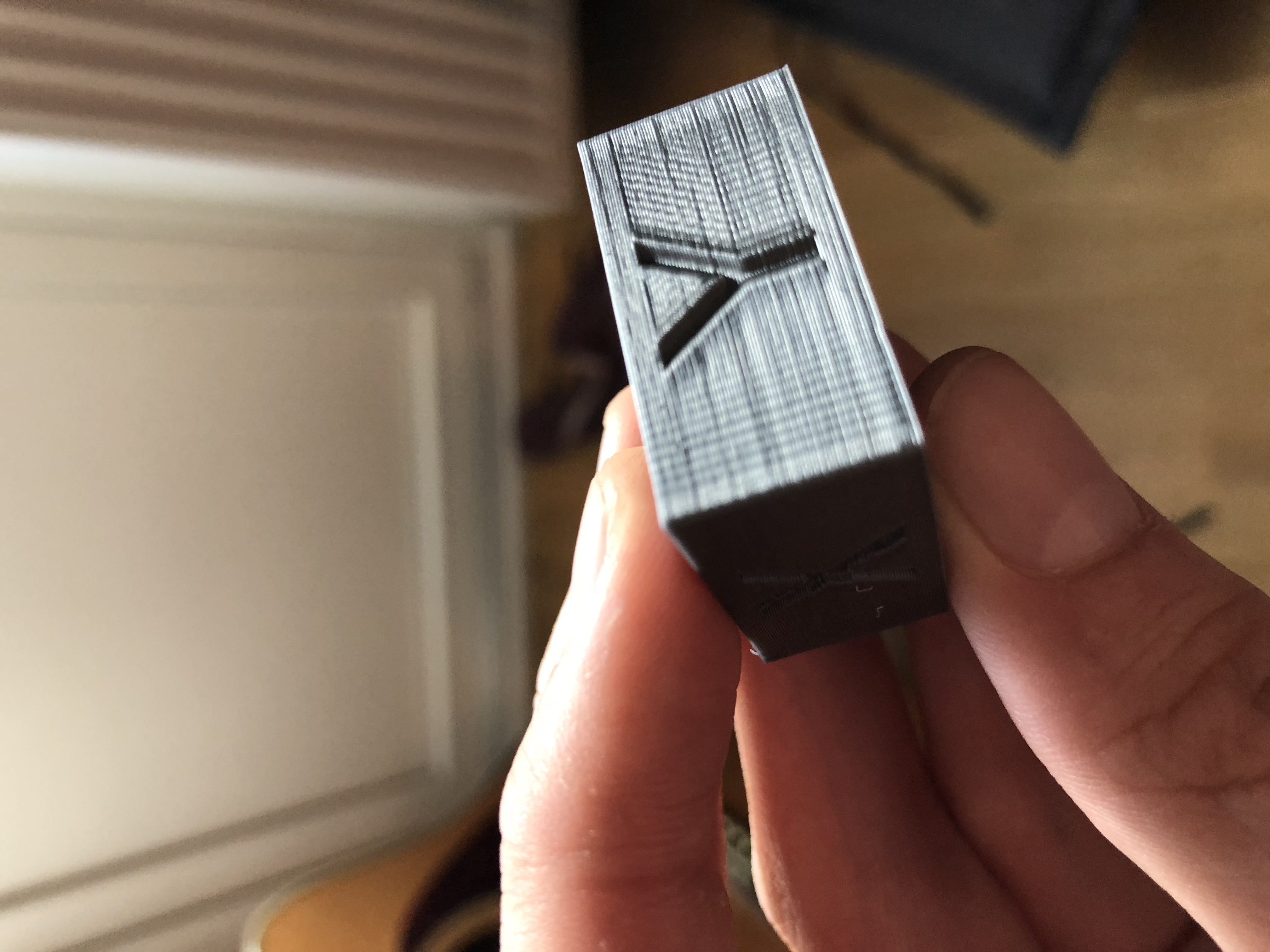
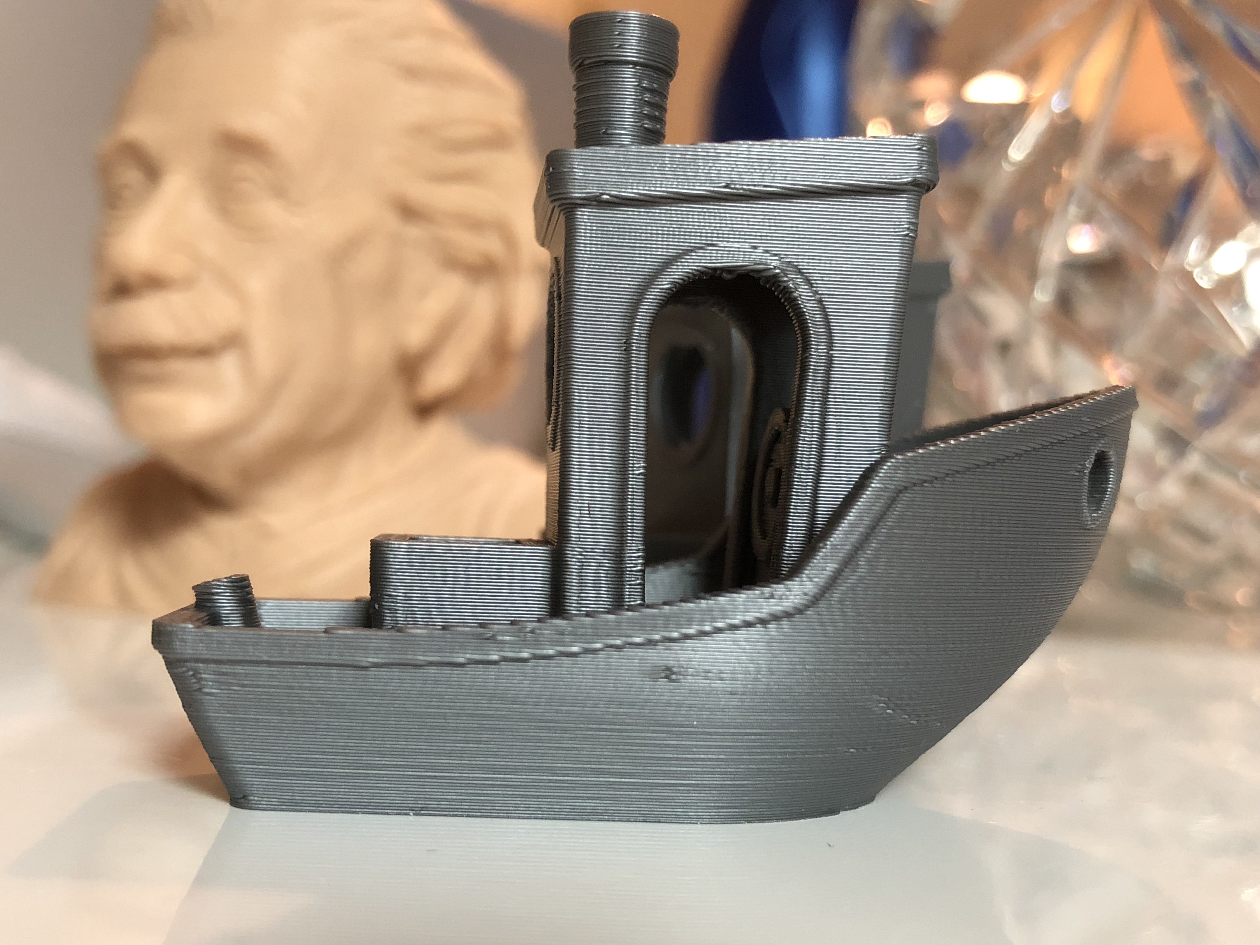
vinjegaard
on 12 May 2018
@vinjegaard
.2 or not the layers still look like crap and should be even more visibly even with .32
Agreed, larger layer heights - if anything - should hand the advantage to the Mk3, but even when having to deal with a finer layer height, the (theoretically) inferior printer, that costs less than half the price of the Mk3, still produces a noticeably better finish !
TynanTynan
on 12 May 2018
@ff8jake: Bowden vs Direct comparison is nothing new. Here is a link to [2014 Reprap forum] (http://forums.reprap.org/read.php?1,344659) . If you scroll down, you will see similar images.
@vinjegaard: No question about room for improvement on MK3. Just want to make sure we compare apples with apples. Otherwise it's hard to find a way to improve it.
workinghard
on 12 May 2018
@workinghard: Of course we probably shouldn't compare DD with bowden but we can all see clearly that the benchy from my previous post has some real issues even without putting another healthy benchy from another DD printer as a comparison.
The light source from above examples are great to enhance the artifacts even if they are worst case scenarios. These artifacts does not appear on my models printed with my I3 clone under the same lighting conditions.
vinjegaard
on 12 May 2018
Hi everyone,
another difference between MK3 and predecessors (but MK2.5 does it IMHO too) is fan tacho/speed reading. Is it an interrupt based approach - I would guess? Maybe it influences motion/stepper timing. @bubnikv would it be a lot of trouble for you to completely disable fan speed reading for a quick test?
stahlfabrik
on 12 May 2018
@stahlfabrik: Yes, it's interrupt based. Don't see how it may influence the stepper. In the interrupt function only one variable is getting written. Looks like an ideal implementation to me. https://github.com/prusa3d/Prusa-Firmware/blob/MK3/Firmware/Marlin_main.cpp Line: 8174
workinghard
on 12 May 2018
So is there a chance that this problem is due to software? or is it hardware? I read through the looong discussion, and I think it would be helpful to gather our(your guys') current ideas so that we can all test possible solutions on our mk3!
On another note, do you guys think that this problem is fixable? I was really expecting MUCH better quality with this printer and I don't know what to do anymore :(
 adham-elarabawy
on 12 May 2018
adham-elarabawy
on 12 May 2018
Just a quick heads up. I updated my MK3 to the version 3.2.0 and run a test again. I can clearly see an improvement. Here is the comparison between MK3 3.1.3/MK3 3.2.0 and MK2S 3.1.0
workinghard
on 12 May 2018
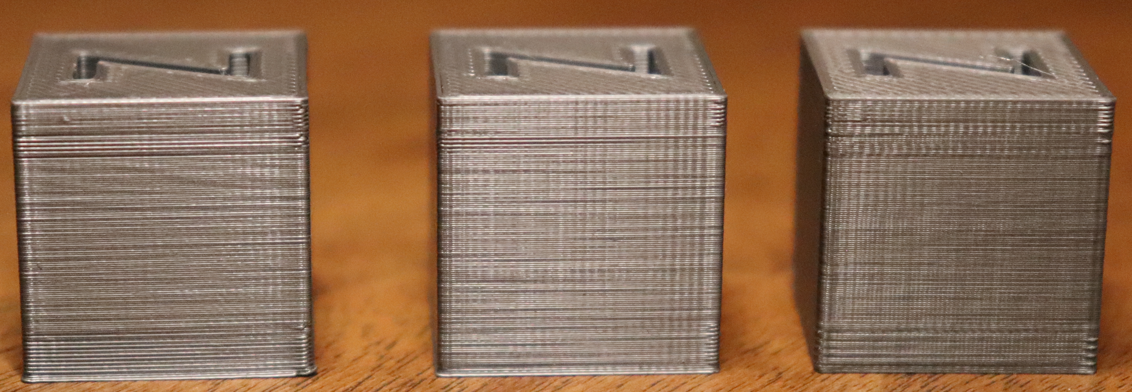
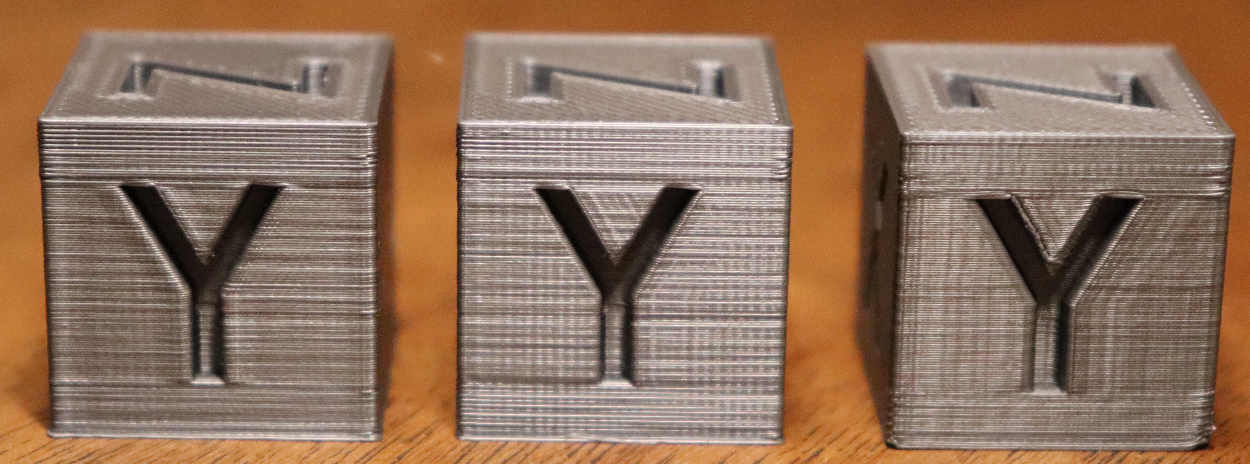
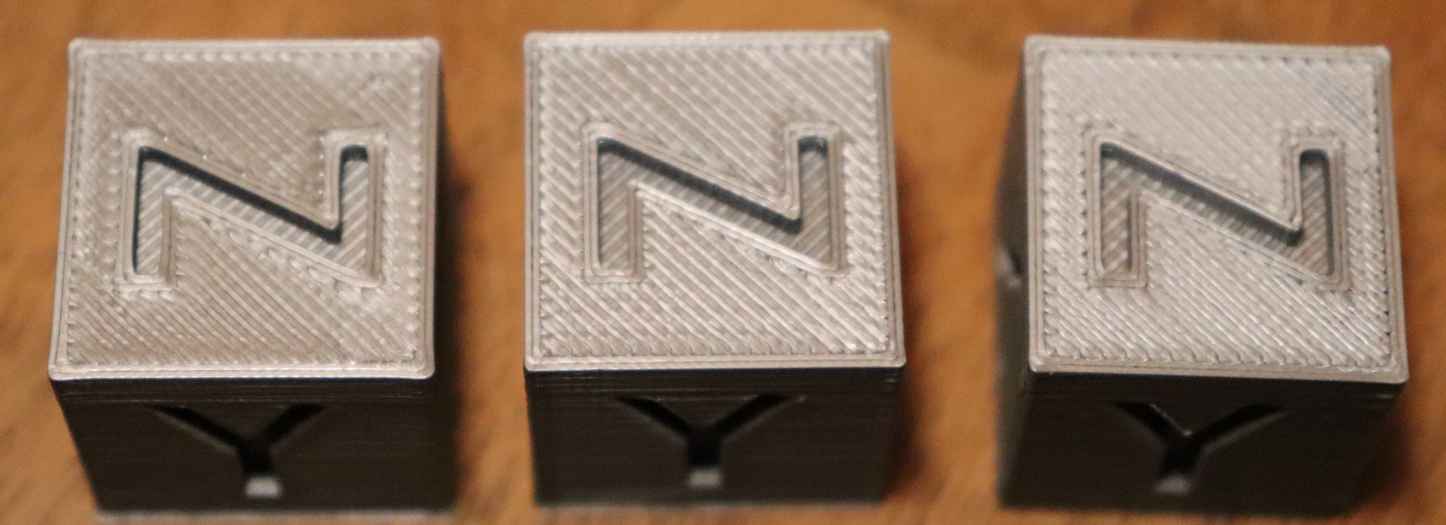
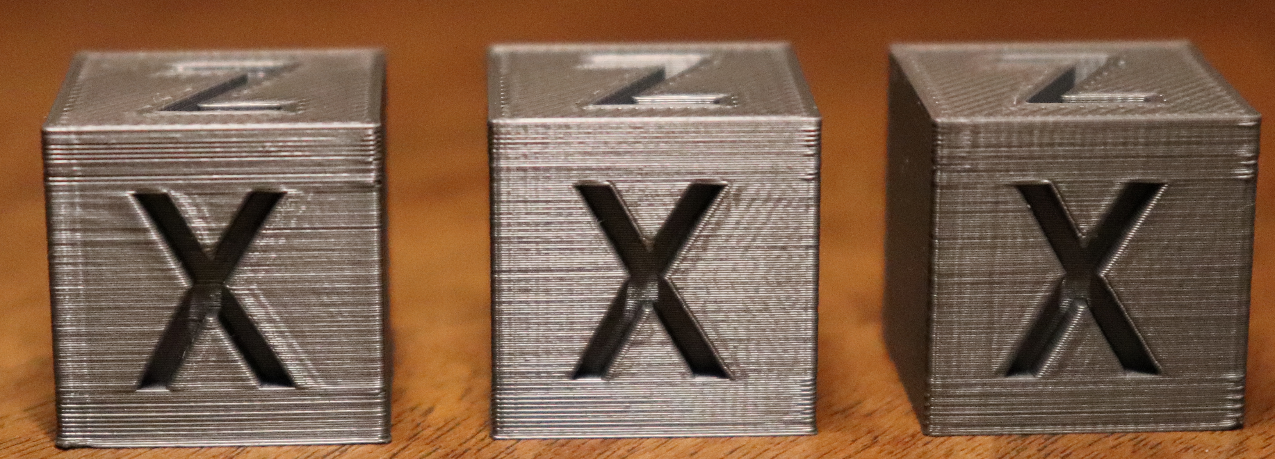
workinghard
on 12 May 2018
I ran the Extruder linearity correction calibration tower test. My results were, well, odd. I didn't see any change moving along the tower. I figured the result was bad because I had other extrusion issues. This wasn't, after all, g-code tweaked to my printer/filament. So I made my own tower stl and applied the following code to the layer change g-code.
{if layer_z==1}TMC_SET_WAVE_E0{endif}
{if layer_z==5}TMC_SET_WAVE_E30{endif}
{if layer_z==10}TMC_SET_WAVE_E40{endif}
{if layer_z==15}TMC_SET_WAVE_E50{endif}
{if layer_z==20}TMC_SET_WAVE_E60{endif}
{if layer_z==25}TMC_SET_WAVE_E70{endif}
{if layer_z==30}TMC_SET_WAVE_E80{endif}
{if layer_z==36}TMC_SET_WAVE_E90{endif}
{if layer_z==41}TMC_SET_WAVE_E100{endif}
{if layer_z==46}TMC_SET_WAVE_E110{endif}
{if layer_z==51}TMC_SET_WAVE_E120{endif}
{if layer_z==56}TMC_SET_WAVE_E130{endif}
{if layer_z==61}TMC_SET_WAVE_E140{endif}
{if layer_z==67}TMC_SET_WAVE_E150{endif}
{if layer_z==72}TMC_SET_WAVE_E160{endif}
{if layer_z==77}TMC_SET_WAVE_E170{endif}
{if layer_z==82}TMC_SET_WAVE_E180{endif}
{if layer_z==87}TMC_SET_WAVE_E190{endif}
{if layer_z==93}TMC_SET_WAVE_E200{endif}
In the photo's my iteration is the one on the far right. The left two are printed using prusa's tower. The odd thing is that the moire effect seems to be moving in a different direction than in prusa's g-code. And in my tower the only thing that seems to change is the angle of moire. Lower in the cube it's closer to 180° but at the top its at 30/40°
Gcode:
https://www.dropbox.com/s/remsfev3au2y1zg/Mano_PLA_MK3_ECOR_TOWER.gcode?dl=0
Stl:
https://www.dropbox.com/s/1cszq0v750q7hyr/Mano_PLA_MK3_ECOR_TOWER.stl?dl=0
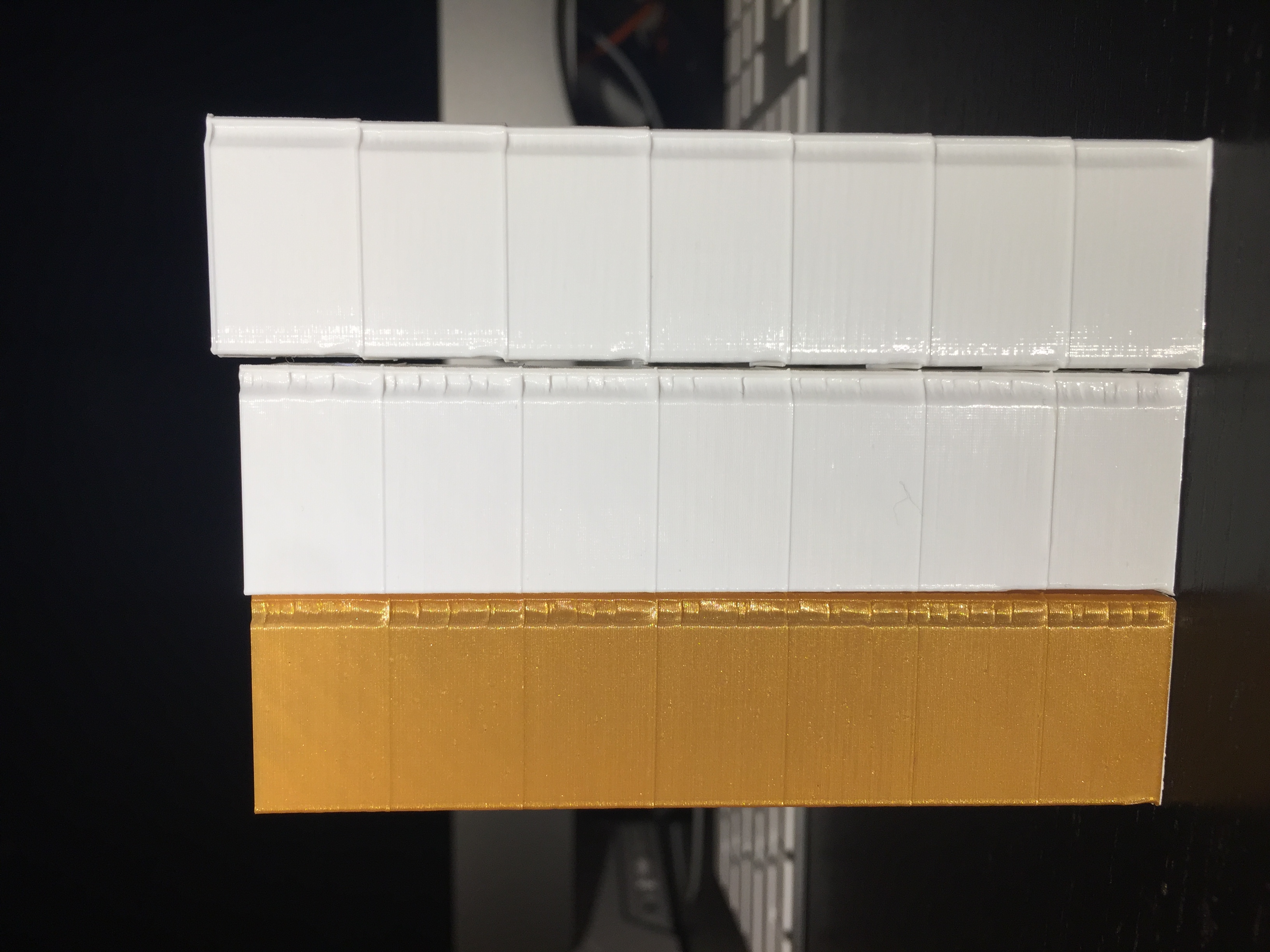
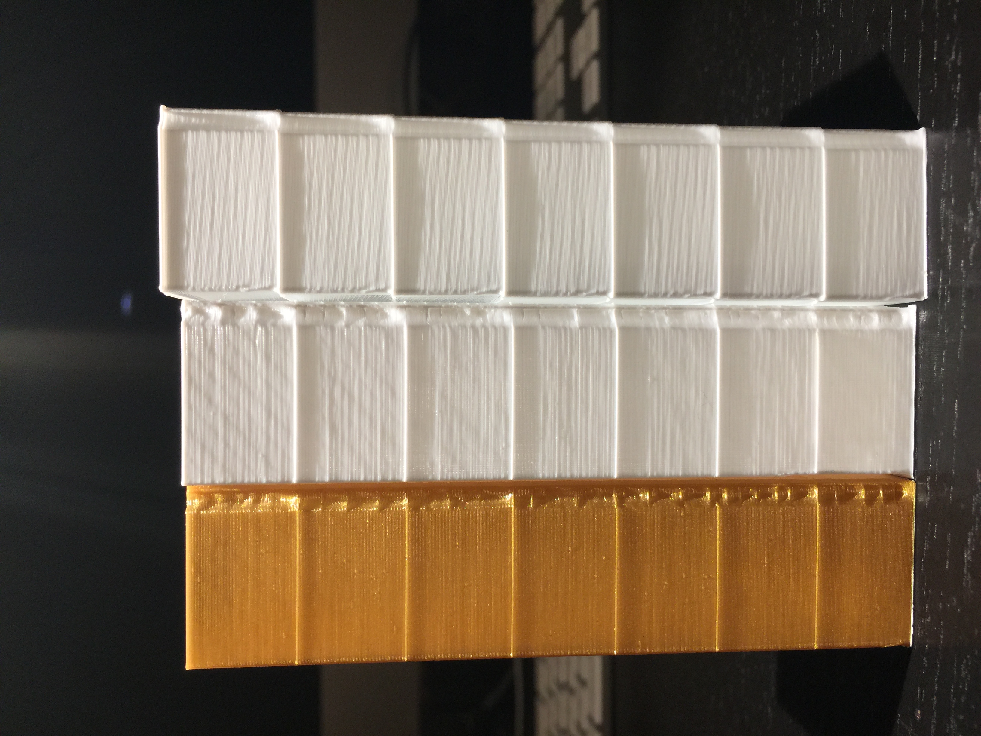
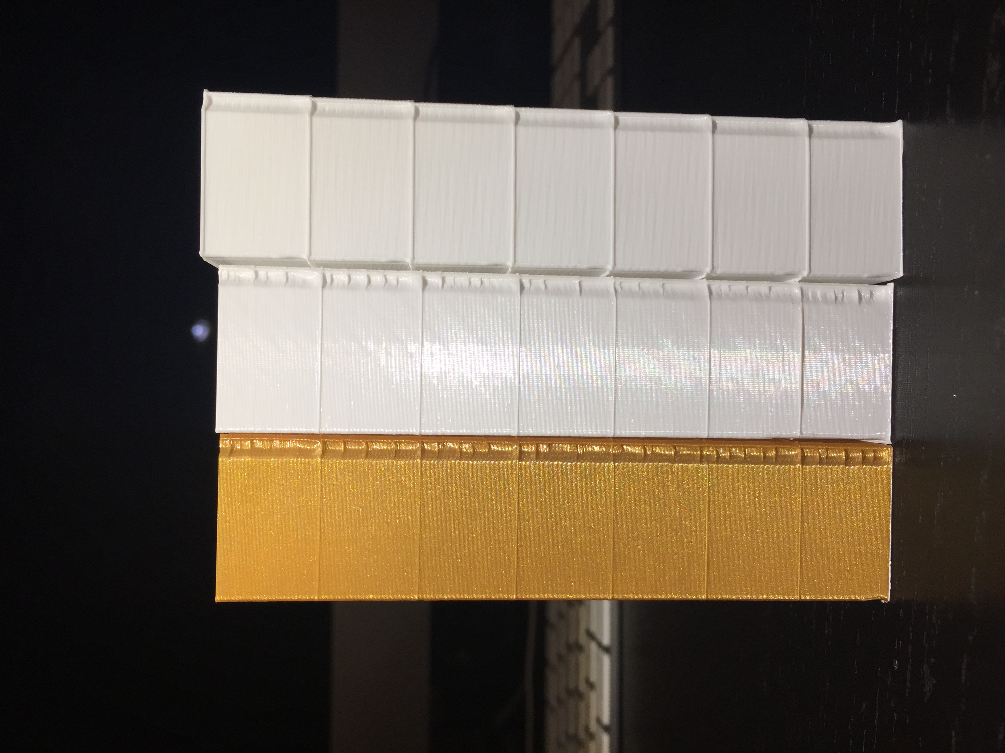
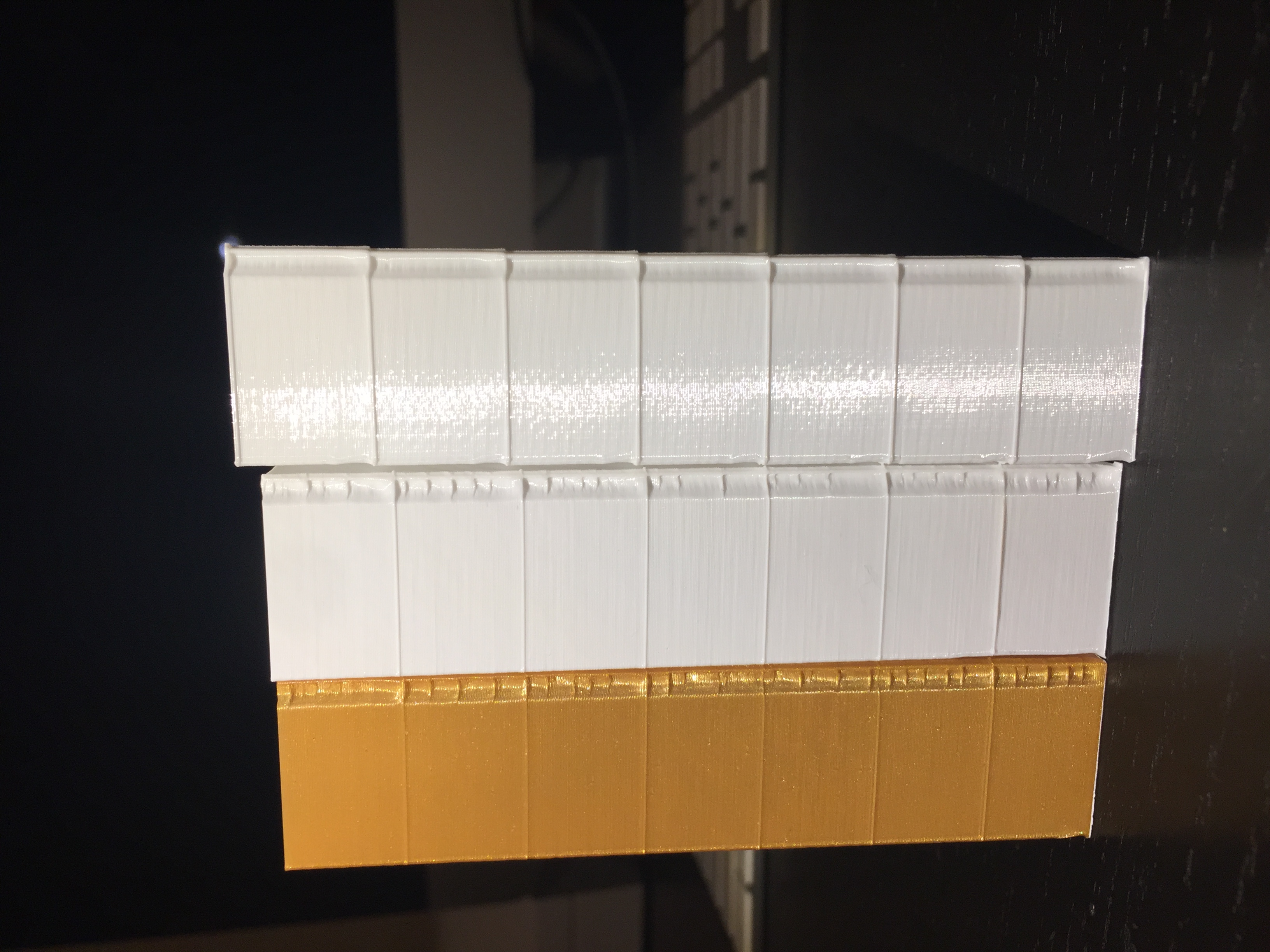
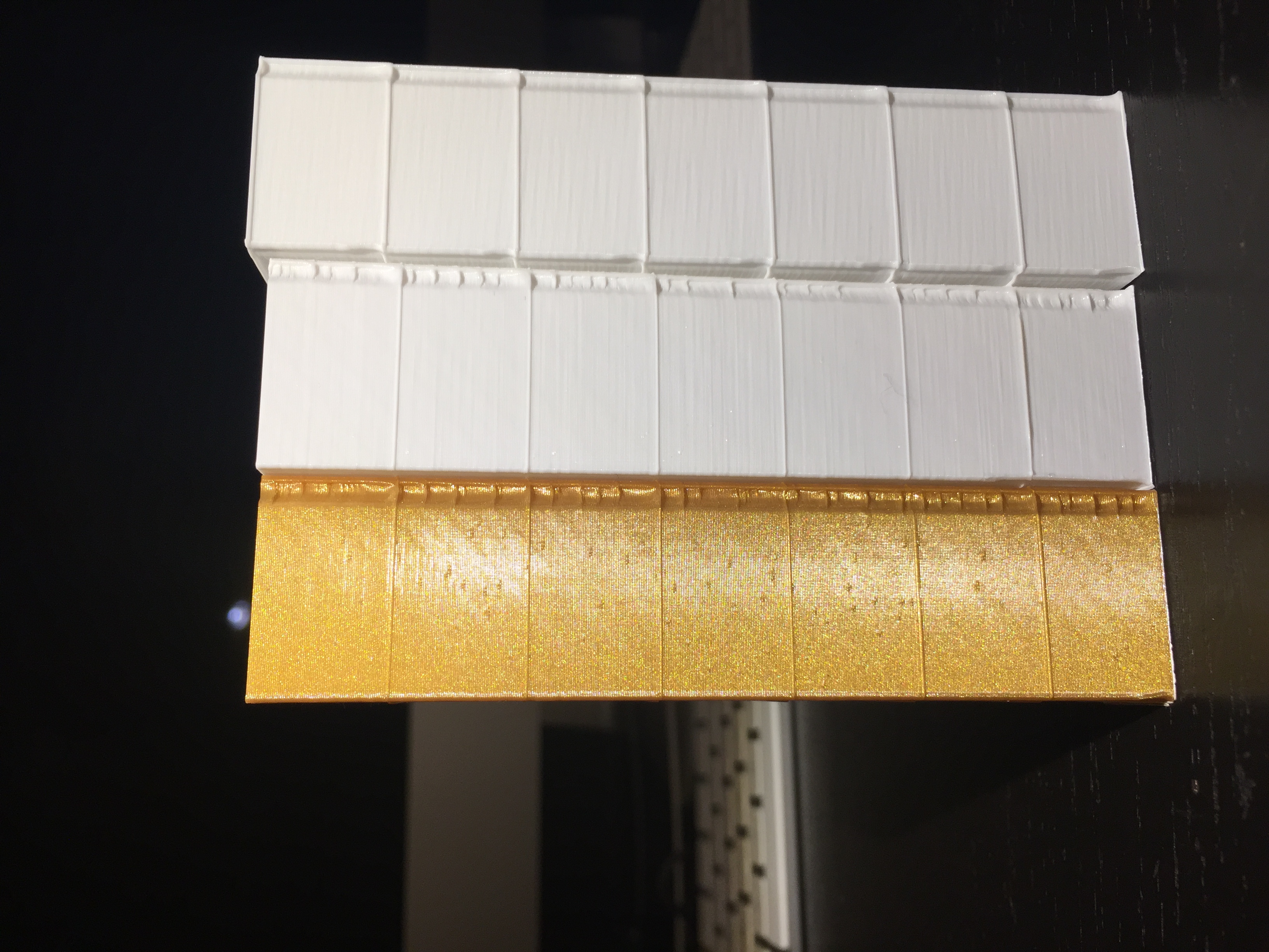
mvasilakis
on 12 May 2018
My mk3 is arriving this Monday and reading this thread, I would be devastated to get that z moire banding result. I did build my own reprap 5 years ago and it has done 30km of filament without any z banding. I got rid off this in my reprap i3 by reducing the acceleration settings. Anyone keen to give this a try?
 paulusjacobus
on 12 May 2018
paulusjacobus
on 12 May 2018
@MoshiBin can you show us exactly which screw in a prusa schematic or picture?
nstis
on 12 May 2018
@nstis it was the green screw in this step http://manual.prusa3d.com/Guide/5.+Extruder+Assembly/295?lang=en#s4997
There was no nut on the other part of the extruder so this screw was spinning freely, which meant that the extruder was not secured in place. Vibrations made it wobble.
MoshiBin
on 12 May 2018
Hello,
I've done the ECOR_TOWER, i'm not able to see real difference between the different values, banding is still here. Everything is correctly tighten, firmware up to date, etc...

eowindel
on 12 May 2018
The moiree E correction thing is IMHO not related to the inconsistent extrusion problem @eowindel
The E co thing is about
--//--//
//--//
while the inconsistent extrusion is about
------
=====
_______
-------
------
______
If you know what I mean:-)
stahlfabrik
on 12 May 2018
@stahlfabrik , Thx i understood how to analyse this now, and found a result of 1.07.
For the extrusion inconsistency, someone try to isolate the E motor cable from the other ? Use of TL smoother ? Change the motor by a cheap chinese wich are installed on cheaper printer ? I want to try a different motor and isolate the cable beacuase i got some in spares, but maybe it has been already tester. I saw in Thomas Sandalerer youtube video that some motor does not act correctly with some drivers.
eowindel
on 12 May 2018
@eowindel I'm pretty sure I've seen these smoothers mentioned earlier in this discussion, and weren't helping. Someone here switches his printer between MK2 and MK2.5 so it's unlikely that the motor is the issue.
MoshiBin
on 12 May 2018
@stahlfabrik
The E co thing is about . . . while the inconsistent extrusion is about . . . If you know what I mean:-)
Here's a quick illustration (for those who don't speak --//--//)

TynanTynan
on 12 May 2018
@paulusjacobus Your verbiage is combining two issues. One of them is the moire which can be mostly tuned out. The second issue is the inconsistent extrusion which we're trying to help Prusa solve. Luckily the issue is mostly present when put under downlighting and the prints generally look great when viewed head on. @stahlfabrik just posted the best illustration above this comment.
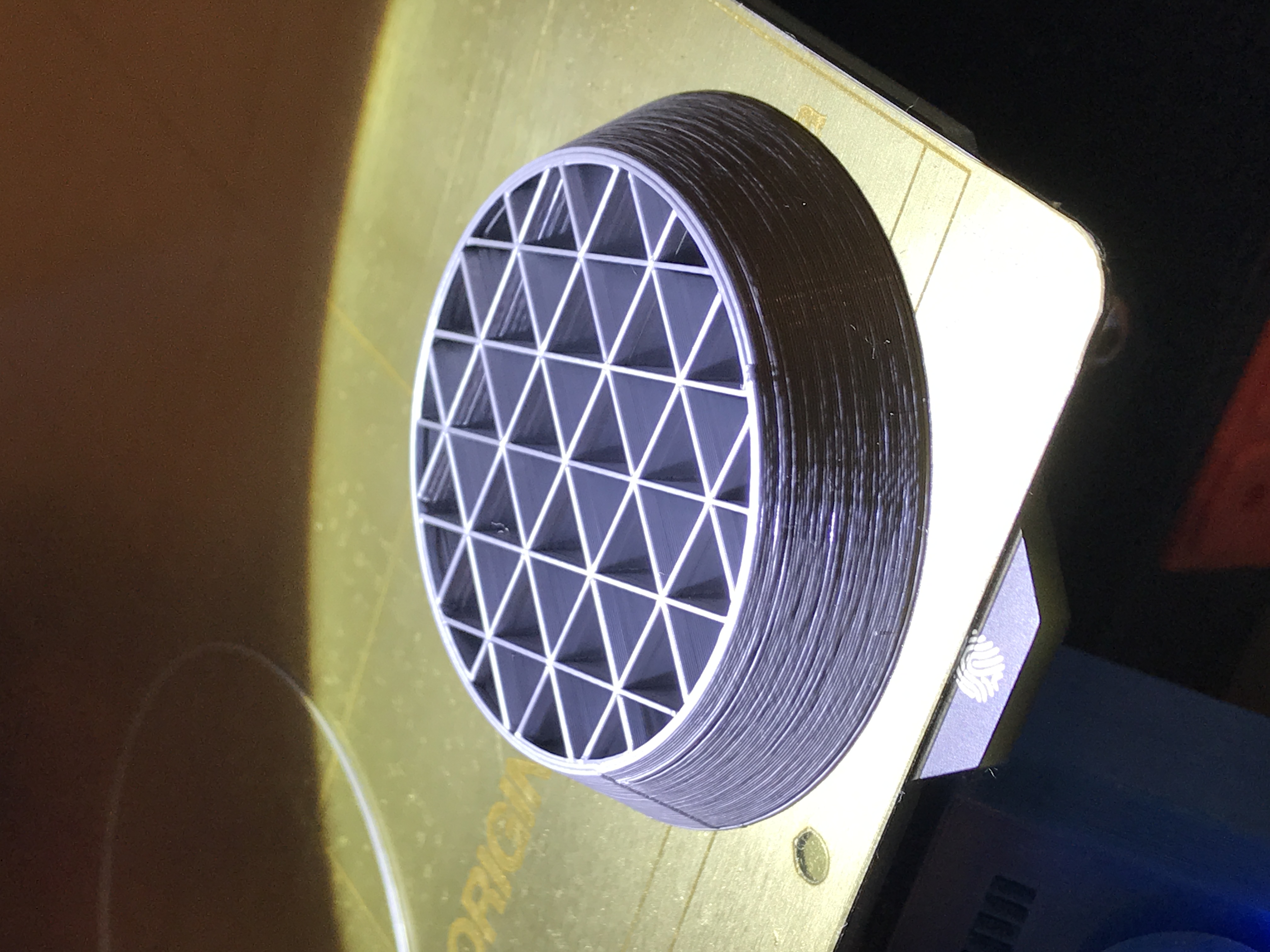
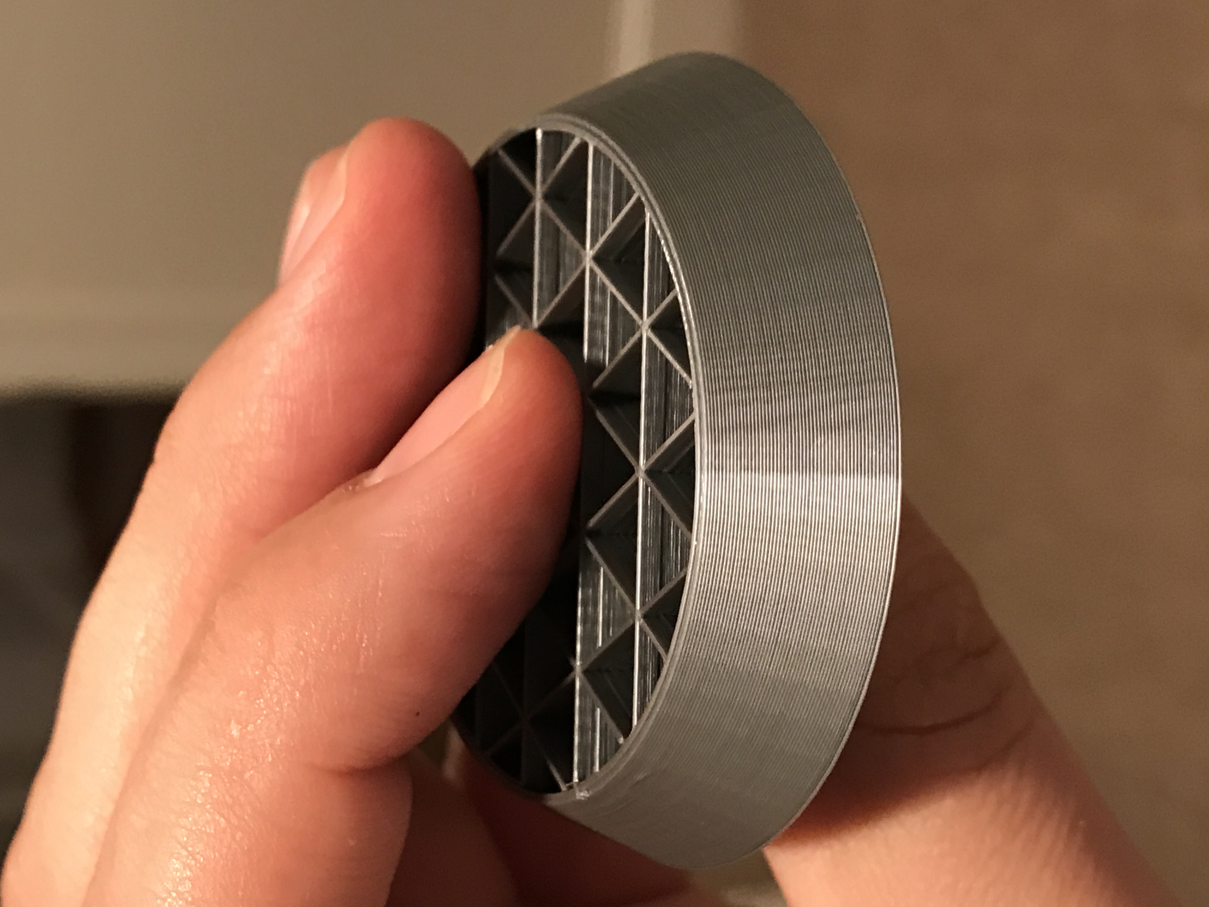
ctilley83
on 12 May 2018
@alientek As requested, I did a new test using silver PLA (Hatchbox), with a flashlight held above to maximize the effect, and shot with a macro lens.
Lit from above (left side is up):
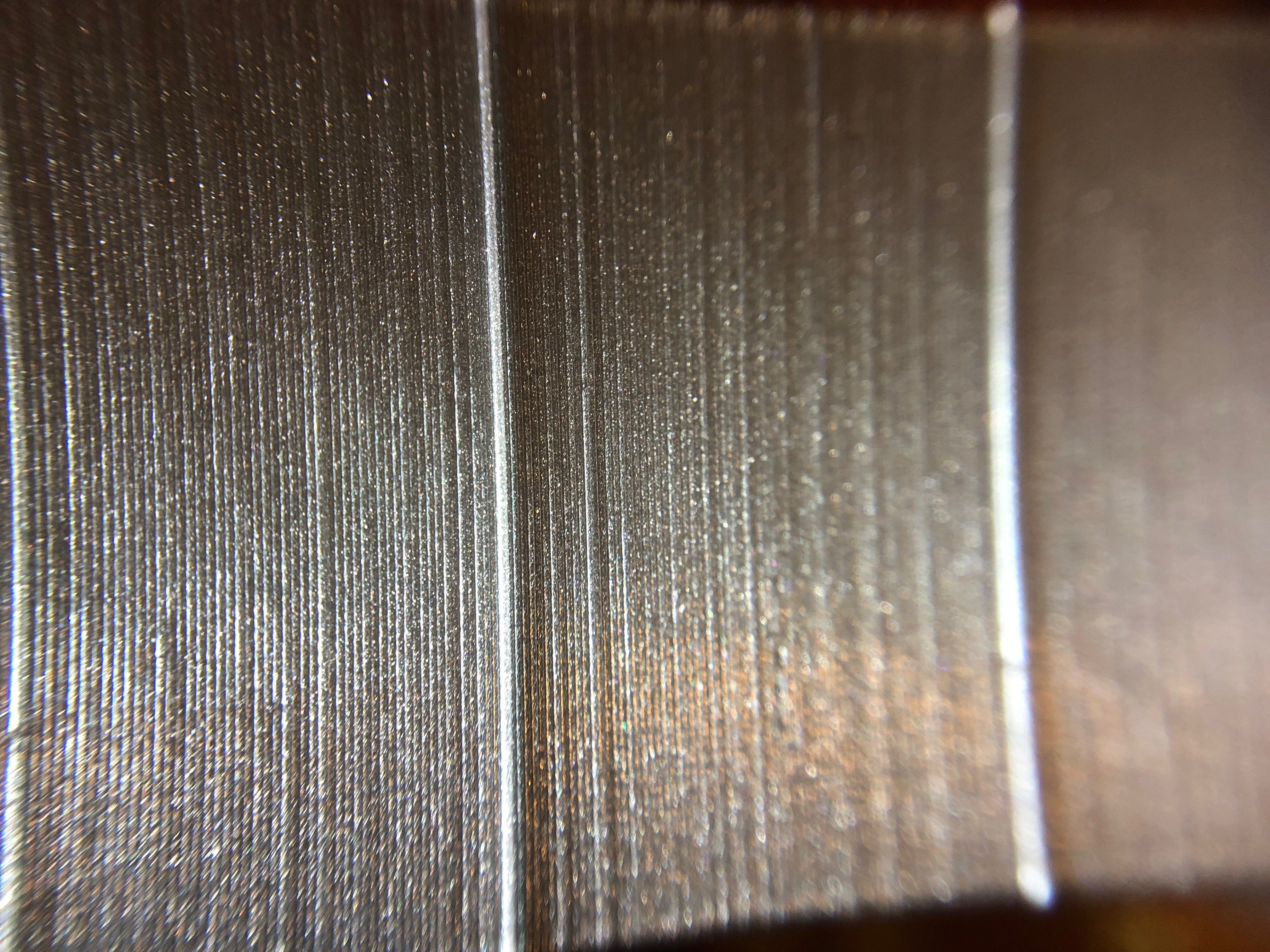
Lit from above + indirectly:
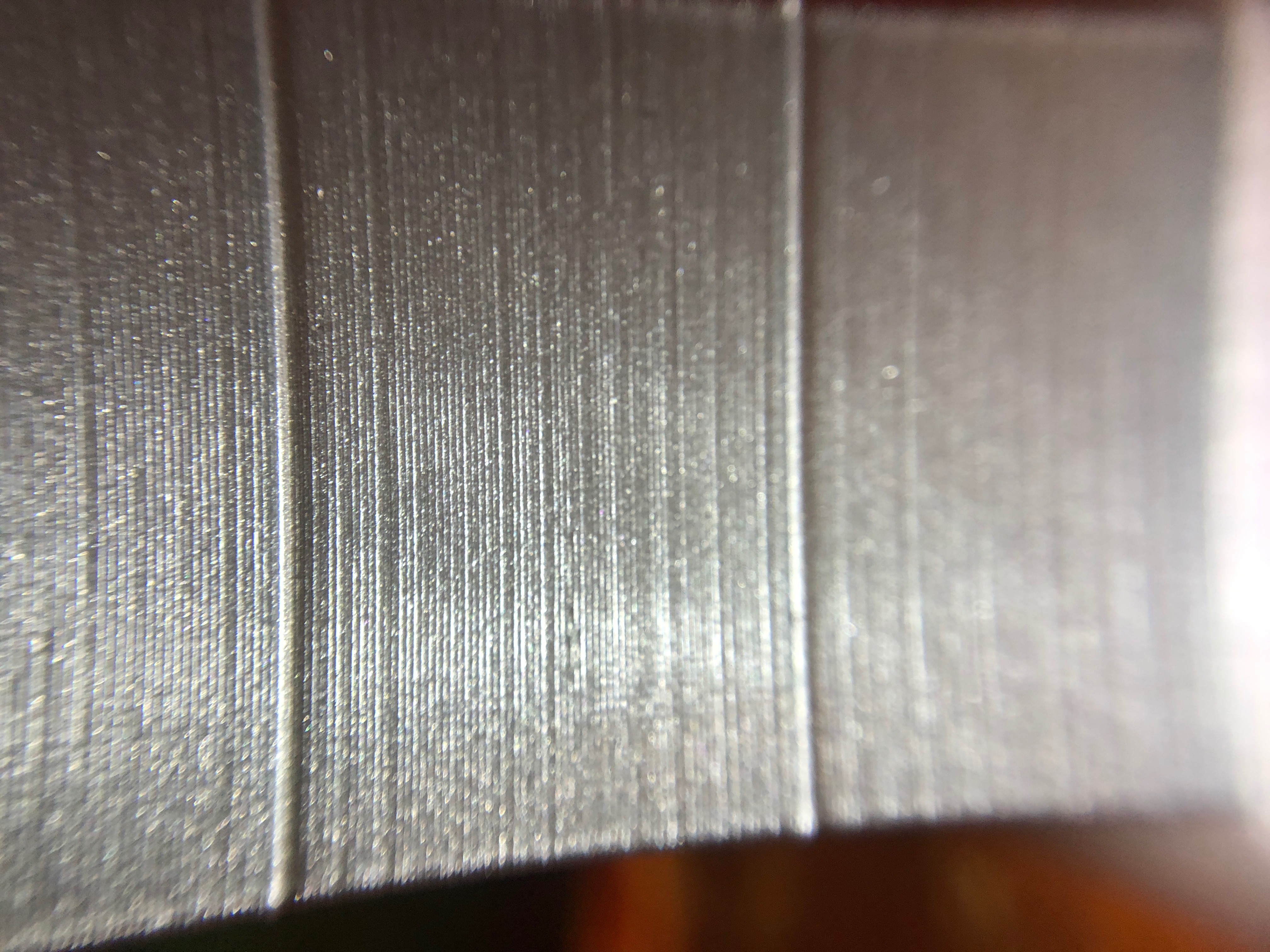
I can see some inconsistencies at this level of magnification, but I think other users are demonstrating issues that are much more dramatic than this.
jettoblack
on 12 May 2018
@jettoblack It doesn't look too bad, but there are some errors. It could be a forgiving plastic like my special white. Is it a kit or assembled?
alientek
on 12 May 2018
Here's another illustration that shows the effect of moving the light from front-on to a more glancing angle from above . . . (causing the inconsistent extrusions to throw shadows onto the surface)

TynanTynan
on 12 May 2018
@tynantynan I am simultaneously impressed at the quality of these demonstrations and depressed that you are having to create them so people understand. :)
For those of you doing the E correction tower, try it on some really clear filament and let light shine through it. Really drives home how this might affect lithos and shows a bit more info on the moire effect than just the surface quality.
TheBrigandier
on 12 May 2018
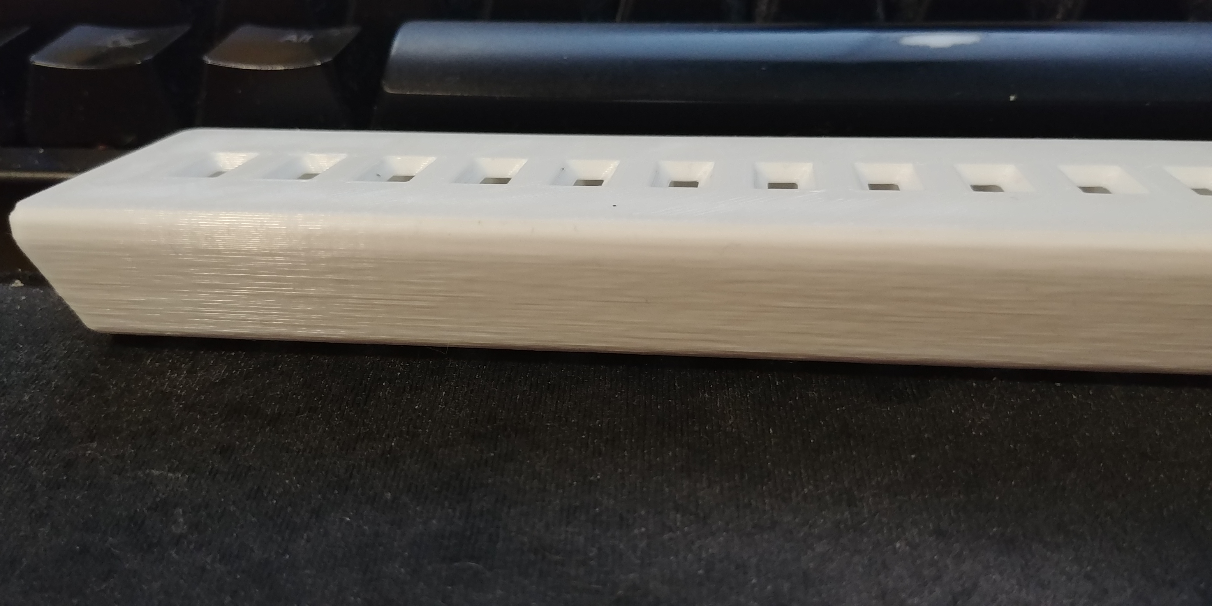
Adding another "Me Too"
 ryanneufeld
on 13 May 2018
ryanneufeld
on 13 May 2018
 AdamMeadowsCRT
on 13 May 2018
stahlfabrik
on 13 May 2018
AdamMeadowsCRT
on 13 May 2018
TheBrigandier
on 13 May 2018
jonbet83
on 13 May 2018
vertigo235
on 13 May 2018
maximlevitsky
on 13 May 2018
vertigo235
on 13 May 2018
TheBrigandier
on 13 May 2018
TheBrigandier
on 13 May 2018
vertigo235
on 13 May 2018
Skiidlive
on 14 May 2018
jettoblack
on 14 May 2018
c-stewart
on 14 May 2018
Skiidlive
on 14 May 2018
TheBrigandier
on 14 May 2018
paulusjacobus
on 14 May 2018
JaseWorthing
on 14 May 2018
TheBrigandier
on 14 May 2018
TheBrigandier
on 14 May 2018
paulusjacobus
on 14 May 2018
JaseWorthing
on 14 May 2018
ctilley83
on 14 May 2018
ctilley83
on 14 May 2018
misan
on 14 May 2018
AdamMeadowsCRT
on 13 May 2018
stahlfabrik
on 13 May 2018
AdamMeadowsCRT
on 13 May 2018
TheBrigandier
on 13 May 2018
jonbet83
on 13 May 2018
vertigo235
on 13 May 2018
maximlevitsky
on 13 May 2018
vertigo235
on 13 May 2018
TheBrigandier
on 13 May 2018
TheBrigandier
on 13 May 2018
vertigo235
on 13 May 2018
Skiidlive
on 14 May 2018
jettoblack
on 14 May 2018
c-stewart
on 14 May 2018
Skiidlive
on 14 May 2018
TheBrigandier
on 14 May 2018
paulusjacobus
on 14 May 2018
JaseWorthing
on 14 May 2018
TheBrigandier
on 14 May 2018
TheBrigandier
on 14 May 2018
paulusjacobus
on 14 May 2018
JaseWorthing
on 14 May 2018
ctilley83
on 14 May 2018
ctilley83
on 14 May 2018
misan
on 14 May 2018
 BrunenG
on 14 May 2018
TynanTynan
on 14 May 2018
BrunenG
on 14 May 2018
TynanTynan
on 14 May 2018
 BK-Morpheus
on 14 May 2018
jonbet83
on 14 May 2018
stahlfabrik
on 14 May 2018
jonbet83
on 14 May 2018
misan
on 14 May 2018
BrunenG
on 14 May 2018
eowindel
on 14 May 2018
stahlfabrik
on 14 May 2018
eowindel
on 14 May 2018
stahlfabrik
on 14 May 2018
BrunenG
on 14 May 2018
TheBrigandier
on 14 May 2018
eowindel
on 14 May 2018
TynanTynan
on 14 May 2018
TheBrigandier
on 14 May 2018
TynanTynan
on 14 May 2018
Skiidlive
on 14 May 2018
ctilley83
on 14 May 2018
vertigo235
on 14 May 2018
TheBrigandier
on 14 May 2018
vertigo235
on 14 May 2018
Skiidlive
on 14 May 2018
TheBrigandier
on 14 May 2018
TheBrigandier
on 14 May 2018
eowindel
on 14 May 2018
BK-Morpheus
on 14 May 2018
jonbet83
on 14 May 2018
stahlfabrik
on 14 May 2018
jonbet83
on 14 May 2018
misan
on 14 May 2018
BrunenG
on 14 May 2018
eowindel
on 14 May 2018
stahlfabrik
on 14 May 2018
eowindel
on 14 May 2018
stahlfabrik
on 14 May 2018
BrunenG
on 14 May 2018
TheBrigandier
on 14 May 2018
eowindel
on 14 May 2018
TynanTynan
on 14 May 2018
TheBrigandier
on 14 May 2018
TynanTynan
on 14 May 2018
Skiidlive
on 14 May 2018
ctilley83
on 14 May 2018
vertigo235
on 14 May 2018
TheBrigandier
on 14 May 2018
vertigo235
on 14 May 2018
Skiidlive
on 14 May 2018
TheBrigandier
on 14 May 2018
TheBrigandier
on 14 May 2018
eowindel
on 14 May 2018
 rrauenza
on 14 May 2018
TheBrigandier
on 14 May 2018
rrauenza
on 14 May 2018
TheBrigandier
on 14 May 2018
 Isaak-Malers
on 14 May 2018
johnlaur
on 14 May 2018
Isaak-Malers
on 14 May 2018
johnlaur
on 14 May 2018
 raspeitia
on 14 May 2018
stahlfabrik
on 14 May 2018
raspeitia
on 14 May 2018
stahlfabrik
on 14 May 2018
venci1ty
on 14 May 2018
venci1ty
on 14 May 2018
raspeitia
on 14 May 2018
stahlfabrik
on 14 May 2018
raspeitia
on 15 May 2018
raspeitia
on 15 May 2018
rrauenza
on 15 May 2018
raspeitia
on 14 May 2018
stahlfabrik
on 14 May 2018
raspeitia
on 14 May 2018
stahlfabrik
on 14 May 2018
venci1ty
on 14 May 2018
venci1ty
on 14 May 2018
raspeitia
on 14 May 2018
stahlfabrik
on 14 May 2018
raspeitia
on 15 May 2018
raspeitia
on 15 May 2018
rrauenza
on 15 May 2018
 Hanwaolo
on 15 May 2018
raspeitia
on 15 May 2018
raspeitia
on 15 May 2018
TheBrigandier
on 15 May 2018
Hanwaolo
on 15 May 2018
c-stewart
on 15 May 2018
TheBrigandier
on 15 May 2018
kwaad2
on 15 May 2018
Hanwaolo
on 15 May 2018
raspeitia
on 15 May 2018
raspeitia
on 15 May 2018
TheBrigandier
on 15 May 2018
Hanwaolo
on 15 May 2018
c-stewart
on 15 May 2018
TheBrigandier
on 15 May 2018
kwaad2
on 15 May 2018
 fiveangle
on 15 May 2018
kwaad2
on 15 May 2018
TheBlueGreen
on 15 May 2018
kwaad2
on 15 May 2018
TheBrigandier
on 15 May 2018
kwaad2
on 15 May 2018
raspeitia
on 15 May 2018
fiveangle
on 15 May 2018
raspeitia
on 15 May 2018
workinghard
on 15 May 2018
raspeitia
on 15 May 2018
workinghard
on 15 May 2018
fiveangle
on 15 May 2018
kwaad2
on 15 May 2018
TheBlueGreen
on 15 May 2018
kwaad2
on 15 May 2018
TheBrigandier
on 15 May 2018
kwaad2
on 15 May 2018
raspeitia
on 15 May 2018
fiveangle
on 15 May 2018
raspeitia
on 15 May 2018
workinghard
on 15 May 2018
raspeitia
on 15 May 2018
workinghard
on 15 May 2018
 clearbucketLabs
on 15 May 2018
raspeitia
on 15 May 2018
TynanTynan
on 15 May 2018
ryanneufeld
on 15 May 2018
TheBrigandier
on 15 May 2018
TynanTynan
on 15 May 2018
TynanTynan
on 15 May 2018
raspeitia
on 15 May 2018
clearbucketLabs
on 15 May 2018
raspeitia
on 15 May 2018
TynanTynan
on 15 May 2018
ryanneufeld
on 15 May 2018
TheBrigandier
on 15 May 2018
TynanTynan
on 15 May 2018
TynanTynan
on 15 May 2018
raspeitia
on 15 May 2018
 mike-serinus
on 15 May 2018
mike-serinus
on 15 May 2018
 MaverickFPV
on 15 May 2018
paulusjacobus
on 15 May 2018
TheBrigandier
on 15 May 2018
ryanneufeld
on 15 May 2018
sneaky-tricky
on 15 May 2018
sneaky-tricky
on 15 May 2018
MaverickFPV
on 15 May 2018
paulusjacobus
on 15 May 2018
TheBrigandier
on 15 May 2018
ryanneufeld
on 15 May 2018
sneaky-tricky
on 15 May 2018
sneaky-tricky
on 15 May 2018
 rocendroll
on 15 May 2018
stahlfabrik
on 15 May 2018
paulusjacobus
on 15 May 2018
rocendroll
on 15 May 2018
stahlfabrik
on 15 May 2018
paulusjacobus
on 15 May 2018
 Glsevans
on 15 May 2018
TynanTynan
on 15 May 2018
cjo20
on 15 May 2018
TynanTynan
on 15 May 2018
rcfsguy
on 15 May 2018
TheBrigandier
on 15 May 2018
raspeitia
on 15 May 2018
Glsevans
on 15 May 2018
TynanTynan
on 15 May 2018
cjo20
on 15 May 2018
TynanTynan
on 15 May 2018
rcfsguy
on 15 May 2018
TheBrigandier
on 15 May 2018
raspeitia
on 15 May 2018
 BryanSmithDev
on 15 May 2018
BryanSmithDev
on 15 May 2018
 vsoto027
on 15 May 2018
raspeitia
on 15 May 2018
nstis
on 15 May 2018
bubnikv
on 15 May 2018
raspeitia
on 15 May 2018
raspeitia
on 15 May 2018
BryanSmithDev
on 15 May 2018
bubnikv
on 15 May 2018
TheBrigandier
on 15 May 2018
rrauenza
on 15 May 2018
vsoto027
on 15 May 2018
raspeitia
on 15 May 2018
nstis
on 15 May 2018
bubnikv
on 15 May 2018
raspeitia
on 15 May 2018
raspeitia
on 15 May 2018
BryanSmithDev
on 15 May 2018
bubnikv
on 15 May 2018
TheBrigandier
on 15 May 2018
rrauenza
on 15 May 2018
 leefla
on 15 May 2018
venci1ty
on 15 May 2018
rrauenza
on 15 May 2018
raspeitia
on 15 May 2018
venci1ty
on 15 May 2018
zafuquazar
on 15 May 2018
sneaky-tricky
on 15 May 2018
ryanneufeld
on 15 May 2018
venci1ty
on 15 May 2018
ryanneufeld
on 15 May 2018
raspeitia
on 15 May 2018
leefla
on 15 May 2018
raspeitia
on 15 May 2018
venci1ty
on 15 May 2018
AdamMeadowsCRT
on 15 May 2018
stahlfabrik
on 15 May 2018
eowindel
on 15 May 2018
AdamMeadowsCRT
on 15 May 2018
leefla
on 15 May 2018
venci1ty
on 15 May 2018
rrauenza
on 15 May 2018
raspeitia
on 15 May 2018
venci1ty
on 15 May 2018
zafuquazar
on 15 May 2018
sneaky-tricky
on 15 May 2018
ryanneufeld
on 15 May 2018
venci1ty
on 15 May 2018
ryanneufeld
on 15 May 2018
raspeitia
on 15 May 2018
leefla
on 15 May 2018
raspeitia
on 15 May 2018
venci1ty
on 15 May 2018
AdamMeadowsCRT
on 15 May 2018
stahlfabrik
on 15 May 2018
eowindel
on 15 May 2018
AdamMeadowsCRT
on 15 May 2018
 sniper85500
on 15 May 2018
TheBrigandier
on 15 May 2018
jonbet83
on 15 May 2018
TheBrigandier
on 15 May 2018
jonbet83
on 15 May 2018
sniper85500
on 15 May 2018
TheBrigandier
on 15 May 2018
jonbet83
on 15 May 2018
TheBrigandier
on 15 May 2018
jonbet83
on 15 May 2018
 Emprint
on 15 May 2018
Emprint
on 15 May 2018
 Chreutz
on 15 May 2018
TheBlueGreen
on 15 May 2018
Chreutz
on 15 May 2018
TheBlueGreen
on 15 May 2018
 moggieuk
on 15 May 2018
AdamMeadowsCRT
on 15 May 2018
rrauenza
on 15 May 2018
TheBlueGreen
on 15 May 2018
venci1ty
on 16 May 2018
raspeitia
on 16 May 2018
rcfsguy
on 16 May 2018
venci1ty
on 16 May 2018
raspeitia
on 16 May 2018
raspeitia
on 16 May 2018
TheBlueGreen
on 16 May 2018
ryanneufeld
on 16 May 2018
rcfsguy
on 16 May 2018
rcfsguy
on 16 May 2018
MaverickFPV
on 16 May 2018
clearbucketLabs
on 16 May 2018
raspeitia
on 16 May 2018
TheBrigandier
on 16 May 2018
TheBrigandier
on 16 May 2018
TheBlueGreen
on 16 May 2018
TheBrigandier
on 16 May 2018
workinghard
on 16 May 2018
BryanSmithDev
on 16 May 2018
vertigo235
on 16 May 2018
moggieuk
on 15 May 2018
AdamMeadowsCRT
on 15 May 2018
rrauenza
on 15 May 2018
TheBlueGreen
on 15 May 2018
venci1ty
on 16 May 2018
raspeitia
on 16 May 2018
rcfsguy
on 16 May 2018
venci1ty
on 16 May 2018
raspeitia
on 16 May 2018
raspeitia
on 16 May 2018
TheBlueGreen
on 16 May 2018
ryanneufeld
on 16 May 2018
rcfsguy
on 16 May 2018
rcfsguy
on 16 May 2018
MaverickFPV
on 16 May 2018
clearbucketLabs
on 16 May 2018
raspeitia
on 16 May 2018
TheBrigandier
on 16 May 2018
TheBrigandier
on 16 May 2018
TheBlueGreen
on 16 May 2018
TheBrigandier
on 16 May 2018
workinghard
on 16 May 2018
BryanSmithDev
on 16 May 2018
vertigo235
on 16 May 2018
 JasonETrowbridge
on 16 May 2018
clearbucketLabs
on 16 May 2018
JasonETrowbridge
on 16 May 2018
clearbucketLabs
on 16 May 2018
Emprint
on 16 May 2018
JasonETrowbridge
on 16 May 2018
JasonETrowbridge
on 16 May 2018
clearbucketLabs
on 16 May 2018
JasonETrowbridge
on 16 May 2018
clearbucketLabs
on 16 May 2018
Emprint
on 16 May 2018
JasonETrowbridge
on 16 May 2018
 hanaleimason
on 16 May 2018
hanaleimason
on 16 May 2018
 bobesa
on 16 May 2018
clearbucketLabs
on 16 May 2018
bobesa
on 16 May 2018
clearbucketLabs
on 16 May 2018
 RKMDesigns
on 16 May 2018
Chreutz
on 16 May 2018
RKMDesigns
on 16 May 2018
clearbucketLabs
on 16 May 2018
RKMDesigns
on 16 May 2018
Panayiotis-git
on 16 May 2018
TheBrigandier
on 16 May 2018
RKMDesigns
on 16 May 2018
udvlp
on 16 May 2018
TheBrigandier
on 16 May 2018
JaseWorthing
on 16 May 2018
RKMDesigns
on 16 May 2018
Chreutz
on 16 May 2018
RKMDesigns
on 16 May 2018
clearbucketLabs
on 16 May 2018
RKMDesigns
on 16 May 2018
Panayiotis-git
on 16 May 2018
TheBrigandier
on 16 May 2018
RKMDesigns
on 16 May 2018
udvlp
on 16 May 2018
TheBrigandier
on 16 May 2018
JaseWorthing
on 16 May 2018
 AbeFM
on 16 May 2018
TheBlueGreen
on 16 May 2018
JaseWorthing
on 16 May 2018
ryanneufeld
on 16 May 2018
BryanSmithDev
on 16 May 2018
AbeFM
on 16 May 2018
TheBlueGreen
on 16 May 2018
JaseWorthing
on 16 May 2018
ryanneufeld
on 16 May 2018
BryanSmithDev
on 16 May 2018
 ATSTWardle
on 16 May 2018
zafuquazar
on 17 May 2018
zafuquazar
on 17 May 2018
JasonETrowbridge
on 17 May 2018
c-stewart
on 17 May 2018
nstis
on 17 May 2018
Chreutz
on 17 May 2018
bubnikv
on 17 May 2018
ATSTWardle
on 16 May 2018
zafuquazar
on 17 May 2018
zafuquazar
on 17 May 2018
JasonETrowbridge
on 17 May 2018
c-stewart
on 17 May 2018
nstis
on 17 May 2018
Chreutz
on 17 May 2018
bubnikv
on 17 May 2018
 marijus75
on 17 May 2018
marijus75
on 17 May 2018
marijus75
on 17 May 2018
marijus75
on 17 May 2018
 rtwlr
on 17 May 2018
bubnikv
on 17 May 2018
TheBlueGreen
on 17 May 2018
stahlfabrik
on 17 May 2018
TheBlueGreen
on 17 May 2018
vertigo235
on 17 May 2018
devilhunter84
on 17 May 2018
rcfsguy
on 17 May 2018
Chreutz
on 17 May 2018
raspeitia
on 17 May 2018
Chreutz
on 17 May 2018
leefla
on 17 May 2018
rtwlr
on 17 May 2018
bubnikv
on 17 May 2018
TheBlueGreen
on 17 May 2018
stahlfabrik
on 17 May 2018
TheBlueGreen
on 17 May 2018
vertigo235
on 17 May 2018
devilhunter84
on 17 May 2018
rcfsguy
on 17 May 2018
Chreutz
on 17 May 2018
raspeitia
on 17 May 2018
Chreutz
on 17 May 2018
leefla
on 17 May 2018
 nerobot
on 17 May 2018
nerobot
on 17 May 2018
 Gybb
on 17 May 2018
Gybb
on 17 May 2018
 Crunch69
on 17 May 2018
Crunch69
on 17 May 2018
 Saij
on 17 May 2018
kwaad2
on 17 May 2018
raspeitia
on 17 May 2018
TynanTynan
on 17 May 2018
ATSTWardle
on 17 May 2018
TheBrigandier
on 17 May 2018
Chreutz
on 17 May 2018
Chreutz
on 17 May 2018
Saij
on 17 May 2018
kwaad2
on 17 May 2018
raspeitia
on 17 May 2018
TynanTynan
on 17 May 2018
ATSTWardle
on 17 May 2018
TheBrigandier
on 17 May 2018
Chreutz
on 17 May 2018
Chreutz
on 17 May 2018
 Zaf9670
on 17 May 2018
Zaf9670
on 17 May 2018
raspeitia
on 17 May 2018
Chreutz
on 17 May 2018
raspeitia
on 17 May 2018
stahlfabrik
on 17 May 2018
ATSTWardle
on 17 May 2018
paulusjacobus
on 17 May 2018
Zaf9670
on 17 May 2018
stahlfabrik
on 17 May 2018
ATSTWardle
on 18 May 2018
leefla
on 18 May 2018
kwaad2
on 18 May 2018
leefla
on 18 May 2018
ATSTWardle
on 18 May 2018
ATSTWardle
on 18 May 2018
leefla
on 18 May 2018
ATSTWardle
on 18 May 2018
ryanneufeld
on 18 May 2018
raspeitia
on 18 May 2018
clearbucketLabs
on 18 May 2018
Chreutz
on 18 May 2018
stahlfabrik
on 18 May 2018
sneaky-tricky
on 18 May 2018
stahlfabrik
on 18 May 2018
jonbet83
on 18 May 2018
Chreutz
on 18 May 2018
jonbet83
on 18 May 2018
Chreutz
on 18 May 2018
ATSTWardle
on 18 May 2018
clearbucketLabs
on 18 May 2018
jonbet83
on 18 May 2018
TheBlueGreen
on 18 May 2018
Chreutz
on 18 May 2018
rcfsguy
on 18 May 2018
RKMDesigns
on 18 May 2018
BryanSmithDev
on 18 May 2018
jonbet83
on 18 May 2018
vertigo235
on 18 May 2018
rrauenza
on 18 May 2018
Chreutz
on 18 May 2018
jdn-za
on 18 May 2018
Zaf9670
on 17 May 2018
Zaf9670
on 17 May 2018
raspeitia
on 17 May 2018
Chreutz
on 17 May 2018
raspeitia
on 17 May 2018
stahlfabrik
on 17 May 2018
ATSTWardle
on 17 May 2018
paulusjacobus
on 17 May 2018
Zaf9670
on 17 May 2018
stahlfabrik
on 17 May 2018
ATSTWardle
on 18 May 2018
leefla
on 18 May 2018
kwaad2
on 18 May 2018
leefla
on 18 May 2018
ATSTWardle
on 18 May 2018
ATSTWardle
on 18 May 2018
leefla
on 18 May 2018
ATSTWardle
on 18 May 2018
ryanneufeld
on 18 May 2018
raspeitia
on 18 May 2018
clearbucketLabs
on 18 May 2018
Chreutz
on 18 May 2018
stahlfabrik
on 18 May 2018
sneaky-tricky
on 18 May 2018
stahlfabrik
on 18 May 2018
jonbet83
on 18 May 2018
Chreutz
on 18 May 2018
jonbet83
on 18 May 2018
Chreutz
on 18 May 2018
ATSTWardle
on 18 May 2018
clearbucketLabs
on 18 May 2018
jonbet83
on 18 May 2018
TheBlueGreen
on 18 May 2018
Chreutz
on 18 May 2018
rcfsguy
on 18 May 2018
RKMDesigns
on 18 May 2018
BryanSmithDev
on 18 May 2018
jonbet83
on 18 May 2018
vertigo235
on 18 May 2018
rrauenza
on 18 May 2018
Chreutz
on 18 May 2018
jdn-za
on 18 May 2018
 lenne0815
on 18 May 2018
TheBrigandier
on 18 May 2018
vertigo235
on 18 May 2018
lenne0815
on 18 May 2018
TheBrigandier
on 18 May 2018
vertigo235
on 18 May 2018
 Arksine
on 18 May 2018
vertigo235
on 18 May 2018
lenne0815
on 18 May 2018
clearbucketLabs
on 18 May 2018
TheBrigandier
on 18 May 2018
clearbucketLabs
on 18 May 2018
rcfsguy
on 18 May 2018
lenne0815
on 18 May 2018
paulusjacobus
on 18 May 2018
clearbucketLabs
on 18 May 2018
TheBrigandier
on 19 May 2018
Arksine
on 18 May 2018
vertigo235
on 18 May 2018
lenne0815
on 18 May 2018
clearbucketLabs
on 18 May 2018
TheBrigandier
on 18 May 2018
clearbucketLabs
on 18 May 2018
rcfsguy
on 18 May 2018
lenne0815
on 18 May 2018
paulusjacobus
on 18 May 2018
clearbucketLabs
on 18 May 2018
TheBrigandier
on 19 May 2018
 goopyplastic
on 19 May 2018
workinghard
on 19 May 2018
vertigo235
on 19 May 2018
goopyplastic
on 19 May 2018
workinghard
on 19 May 2018
vertigo235
on 19 May 2018
 danclarke
on 19 May 2018
BryanSmithDev
on 19 May 2018
danclarke
on 19 May 2018
TheBrigandier
on 19 May 2018
danclarke
on 19 May 2018
BryanSmithDev
on 19 May 2018
danclarke
on 19 May 2018
TheBrigandier
on 19 May 2018
 Faceless3D
on 19 May 2018
Dioblieum
on 19 May 2018
leefla
on 19 May 2018
Faceless3D
on 19 May 2018
Dioblieum
on 19 May 2018
leefla
on 19 May 2018
 brnl
on 19 May 2018
TheBrigandier
on 19 May 2018
brnl
on 19 May 2018
TheBrigandier
on 19 May 2018
mvasilakis
on 19 May 2018
rrauenza
on 19 May 2018
brnl
on 19 May 2018
TheBrigandier
on 19 May 2018
brnl
on 19 May 2018
TheBrigandier
on 19 May 2018
mvasilakis
on 19 May 2018
rrauenza
on 19 May 2018
 RockSlice
on 19 May 2018
ryanneufeld
on 19 May 2018
RockSlice
on 19 May 2018
AbeFM
on 19 May 2018
leefla
on 19 May 2018
brnl
on 19 May 2018
brnl
on 19 May 2018
leefla
on 19 May 2018
TheBrigandier
on 19 May 2018
Skiidlive
on 19 May 2018
leefla
on 19 May 2018
brnl
on 19 May 2018
leefla
on 19 May 2018
leefla
on 19 May 2018
brnl
on 19 May 2018
brnl
on 19 May 2018
MTJC
on 19 May 2018
brnl
on 19 May 2018
Zaf9670
on 19 May 2018
BryanSmithDev
on 19 May 2018
AbeFM
on 19 May 2018
MTJC
on 19 May 2018
brnl
on 19 May 2018
TheBrigandier
on 19 May 2018
brnl
on 19 May 2018
RockSlice
on 19 May 2018
ryanneufeld
on 19 May 2018
RockSlice
on 19 May 2018
AbeFM
on 19 May 2018
leefla
on 19 May 2018
brnl
on 19 May 2018
brnl
on 19 May 2018
leefla
on 19 May 2018
TheBrigandier
on 19 May 2018
Skiidlive
on 19 May 2018
leefla
on 19 May 2018
brnl
on 19 May 2018
leefla
on 19 May 2018
leefla
on 19 May 2018
brnl
on 19 May 2018
brnl
on 19 May 2018
MTJC
on 19 May 2018
brnl
on 19 May 2018
Zaf9670
on 19 May 2018
BryanSmithDev
on 19 May 2018
AbeFM
on 19 May 2018
MTJC
on 19 May 2018
brnl
on 19 May 2018
TheBrigandier
on 19 May 2018
brnl
on 19 May 2018
 IluvatarBZH
on 19 May 2018
brnl
on 19 May 2018
brnl
on 19 May 2018
Chreutz
on 19 May 2018
brnl
on 19 May 2018
IluvatarBZH
on 19 May 2018
brnl
on 19 May 2018
brnl
on 19 May 2018
Chreutz
on 19 May 2018
brnl
on 19 May 2018
 freaky-m0
on 19 May 2018
brnl
on 19 May 2018
sneaky-tricky
on 19 May 2018
IluvatarBZH
on 19 May 2018
brnl
on 19 May 2018
IluvatarBZH
on 19 May 2018
sneaky-tricky
on 19 May 2018
vertigo235
on 19 May 2018
sneaky-tricky
on 19 May 2018
devilhunter84
on 19 May 2018
sneaky-tricky
on 19 May 2018
vertigo235
on 19 May 2018
freaky-m0
on 19 May 2018
brnl
on 19 May 2018
sneaky-tricky
on 19 May 2018
IluvatarBZH
on 19 May 2018
brnl
on 19 May 2018
IluvatarBZH
on 19 May 2018
sneaky-tricky
on 19 May 2018
vertigo235
on 19 May 2018
sneaky-tricky
on 19 May 2018
devilhunter84
on 19 May 2018
sneaky-tricky
on 19 May 2018
vertigo235
on 19 May 2018
 ronmacmedia
on 20 May 2018
ronmacmedia
on 20 May 2018
 TTN-
on 20 May 2018
vertigo235
on 20 May 2018
paulusjacobus
on 20 May 2018
TTN-
on 20 May 2018
vertigo235
on 20 May 2018
paulusjacobus
on 20 May 2018
 mlewus
on 20 May 2018
Chreutz
on 20 May 2018
Gybb
on 20 May 2018
leefla
on 21 May 2018
johnlaur
on 21 May 2018
mlewus
on 20 May 2018
Chreutz
on 20 May 2018
Gybb
on 20 May 2018
leefla
on 21 May 2018
johnlaur
on 21 May 2018
 hobsie
on 21 May 2018
stahlfabrik
on 21 May 2018
hobsie
on 21 May 2018
leefla
on 21 May 2018
clearbucketLabs
on 22 May 2018
leefla
on 22 May 2018
hobsie
on 21 May 2018
stahlfabrik
on 21 May 2018
hobsie
on 21 May 2018
leefla
on 21 May 2018
clearbucketLabs
on 22 May 2018
leefla
on 22 May 2018
 Juansejo
on 22 May 2018
Gybb
on 22 May 2018
hobsie
on 22 May 2018
Juansejo
on 22 May 2018
Gybb
on 22 May 2018
hobsie
on 22 May 2018
 lpgreini
on 22 May 2018
nstis
on 22 May 2018
TheBrigandier
on 22 May 2018
Gybb
on 22 May 2018
hobsie
on 22 May 2018
lpgreini
on 22 May 2018
nstis
on 22 May 2018
TheBrigandier
on 22 May 2018
Gybb
on 22 May 2018
hobsie
on 22 May 2018
 murphy2712
on 22 May 2018
Panayiotis-git
on 22 May 2018
murphy2712
on 22 May 2018
Panayiotis-git
on 22 May 2018
 LOLDERS
on 22 May 2018
LOLDERS
on 22 May 2018
sneaky-tricky
on 22 May 2018
LOLDERS
on 22 May 2018
LOLDERS
on 22 May 2018
LOLDERS
on 22 May 2018
sneaky-tricky
on 22 May 2018
LOLDERS
on 22 May 2018
 Seikilos
on 22 May 2018
LOLDERS
on 22 May 2018
LOLDERS
on 22 May 2018
Juansejo
on 22 May 2018
workinghard
on 22 May 2018
Juansejo
on 22 May 2018
jonbet83
on 22 May 2018
TheBrigandier
on 22 May 2018
TheBrigandier
on 22 May 2018
Gybb
on 22 May 2018
c-stewart
on 22 May 2018
nstis
on 22 May 2018
hobsie
on 22 May 2018
c-stewart
on 23 May 2018
TheBrigandier
on 23 May 2018
ryanneufeld
on 23 May 2018
TheBrigandier
on 23 May 2018
ryanneufeld
on 23 May 2018
leefla
on 23 May 2018
TheBrigandier
on 23 May 2018
TheBrigandier
on 23 May 2018
raspeitia
on 23 May 2018
raspeitia
on 23 May 2018
raspeitia
on 23 May 2018
sneaky-tricky
on 23 May 2018
raspeitia
on 23 May 2018
clearbucketLabs
on 23 May 2018
jonbet83
on 23 May 2018
LOLDERS
on 23 May 2018
LOLDERS
on 23 May 2018
LOLDERS
on 23 May 2018
MTJC
on 23 May 2018
LOLDERS
on 23 May 2018
murphy2712
on 23 May 2018
MTJC
on 23 May 2018
LOLDERS
on 23 May 2018
LOLDERS
on 23 May 2018
LOLDERS
on 23 May 2018
MTJC
on 23 May 2018
Seikilos
on 23 May 2018
LOLDERS
on 23 May 2018
LOLDERS
on 23 May 2018
LOLDERS
on 23 May 2018
Seikilos
on 22 May 2018
LOLDERS
on 22 May 2018
LOLDERS
on 22 May 2018
Juansejo
on 22 May 2018
workinghard
on 22 May 2018
Juansejo
on 22 May 2018
jonbet83
on 22 May 2018
TheBrigandier
on 22 May 2018
TheBrigandier
on 22 May 2018
Gybb
on 22 May 2018
c-stewart
on 22 May 2018
nstis
on 22 May 2018
hobsie
on 22 May 2018
c-stewart
on 23 May 2018
TheBrigandier
on 23 May 2018
ryanneufeld
on 23 May 2018
TheBrigandier
on 23 May 2018
ryanneufeld
on 23 May 2018
leefla
on 23 May 2018
TheBrigandier
on 23 May 2018
TheBrigandier
on 23 May 2018
raspeitia
on 23 May 2018
raspeitia
on 23 May 2018
raspeitia
on 23 May 2018
sneaky-tricky
on 23 May 2018
raspeitia
on 23 May 2018
clearbucketLabs
on 23 May 2018
jonbet83
on 23 May 2018
LOLDERS
on 23 May 2018
LOLDERS
on 23 May 2018
LOLDERS
on 23 May 2018
MTJC
on 23 May 2018
LOLDERS
on 23 May 2018
murphy2712
on 23 May 2018
MTJC
on 23 May 2018
LOLDERS
on 23 May 2018
LOLDERS
on 23 May 2018
LOLDERS
on 23 May 2018
MTJC
on 23 May 2018
Seikilos
on 23 May 2018
LOLDERS
on 23 May 2018
LOLDERS
on 23 May 2018
LOLDERS
on 23 May 2018
 andrewebling
on 23 May 2018
LOLDERS
on 23 May 2018
MTJC
on 23 May 2018
LOLDERS
on 23 May 2018
cjo20
on 23 May 2018
clearbucketLabs
on 23 May 2018
clearbucketLabs
on 23 May 2018
TheBrigandier
on 23 May 2018
andrewebling
on 23 May 2018
LOLDERS
on 23 May 2018
MTJC
on 23 May 2018
LOLDERS
on 23 May 2018
cjo20
on 23 May 2018
clearbucketLabs
on 23 May 2018
clearbucketLabs
on 23 May 2018
TheBrigandier
on 23 May 2018
 eikonic
on 23 May 2018
andrewebling
on 23 May 2018
murphy2712
on 23 May 2018
sneaky-tricky
on 23 May 2018
vsoto027
on 23 May 2018
murphy2712
on 23 May 2018
sneaky-tricky
on 23 May 2018
MarcusAdams
on 23 May 2018
cjo20
on 23 May 2018
murphy2712
on 23 May 2018
MarcusAdams
on 23 May 2018
jonbet83
on 23 May 2018
cjo20
on 23 May 2018
johnlaur
on 23 May 2018
jonbet83
on 23 May 2018
rrauenza
on 23 May 2018
eikonic
on 23 May 2018
andrewebling
on 23 May 2018
murphy2712
on 23 May 2018
sneaky-tricky
on 23 May 2018
vsoto027
on 23 May 2018
murphy2712
on 23 May 2018
sneaky-tricky
on 23 May 2018
MarcusAdams
on 23 May 2018
cjo20
on 23 May 2018
murphy2712
on 23 May 2018
MarcusAdams
on 23 May 2018
jonbet83
on 23 May 2018
cjo20
on 23 May 2018
johnlaur
on 23 May 2018
jonbet83
on 23 May 2018
rrauenza
on 23 May 2018
 gdombiak
on 23 May 2018
clearbucketLabs
on 23 May 2018
TheBrigandier
on 23 May 2018
MarcusAdams
on 23 May 2018
clearbucketLabs
on 23 May 2018
cjo20
on 23 May 2018
gdombiak
on 23 May 2018
clearbucketLabs
on 23 May 2018
clearbucketLabs
on 23 May 2018
TheBrigandier
on 23 May 2018
stahlfabrik
on 23 May 2018
TheBrigandier
on 23 May 2018
stahlfabrik
on 23 May 2018
rrauenza
on 23 May 2018
rrauenza
on 23 May 2018
JasonETrowbridge
on 23 May 2018
JasonETrowbridge
on 23 May 2018
vertigo235
on 23 May 2018
rrauenza
on 23 May 2018
Isaak-Malers
on 23 May 2018
rrauenza
on 23 May 2018
sniper85500
on 23 May 2018
sneaky-tricky
on 23 May 2018
stahlfabrik
on 23 May 2018
rrauenza
on 23 May 2018
MoshiBin
on 23 May 2018
TheBrigandier
on 23 May 2018
JasonETrowbridge
on 23 May 2018
nstis
on 23 May 2018
rrauenza
on 23 May 2018
rrauenza
on 23 May 2018
JasonETrowbridge
on 23 May 2018
sneaky-tricky
on 23 May 2018
JasonETrowbridge
on 23 May 2018
JasonETrowbridge
on 23 May 2018
nstis
on 23 May 2018
sneaky-tricky
on 23 May 2018
Dioblieum
on 23 May 2018
Gybb
on 23 May 2018
sneaky-tricky
on 23 May 2018
devilhunter84
on 23 May 2018
vertigo235
on 23 May 2018
vertigo235
on 23 May 2018
TheBrigandier
on 23 May 2018
ryanneufeld
on 23 May 2018
TheBrigandier
on 23 May 2018
ryanneufeld
on 23 May 2018
kwaad2
on 24 May 2018
gdombiak
on 23 May 2018
clearbucketLabs
on 23 May 2018
TheBrigandier
on 23 May 2018
MarcusAdams
on 23 May 2018
clearbucketLabs
on 23 May 2018
cjo20
on 23 May 2018
gdombiak
on 23 May 2018
clearbucketLabs
on 23 May 2018
clearbucketLabs
on 23 May 2018
TheBrigandier
on 23 May 2018
stahlfabrik
on 23 May 2018
TheBrigandier
on 23 May 2018
stahlfabrik
on 23 May 2018
rrauenza
on 23 May 2018
rrauenza
on 23 May 2018
JasonETrowbridge
on 23 May 2018
JasonETrowbridge
on 23 May 2018
vertigo235
on 23 May 2018
rrauenza
on 23 May 2018
Isaak-Malers
on 23 May 2018
rrauenza
on 23 May 2018
sniper85500
on 23 May 2018
sneaky-tricky
on 23 May 2018
stahlfabrik
on 23 May 2018
rrauenza
on 23 May 2018
MoshiBin
on 23 May 2018
TheBrigandier
on 23 May 2018
JasonETrowbridge
on 23 May 2018
nstis
on 23 May 2018
rrauenza
on 23 May 2018
rrauenza
on 23 May 2018
JasonETrowbridge
on 23 May 2018
sneaky-tricky
on 23 May 2018
JasonETrowbridge
on 23 May 2018
JasonETrowbridge
on 23 May 2018
nstis
on 23 May 2018
sneaky-tricky
on 23 May 2018
Dioblieum
on 23 May 2018
Gybb
on 23 May 2018
sneaky-tricky
on 23 May 2018
devilhunter84
on 23 May 2018
vertigo235
on 23 May 2018
vertigo235
on 23 May 2018
TheBrigandier
on 23 May 2018
ryanneufeld
on 23 May 2018
TheBrigandier
on 23 May 2018
ryanneufeld
on 23 May 2018
kwaad2
on 24 May 2018
 metacollin
on 24 May 2018
devilhunter84
on 24 May 2018
metacollin
on 24 May 2018
metacollin
on 24 May 2018
devilhunter84
on 24 May 2018
metacollin
on 24 May 2018
 pache11
on 24 May 2018
leefla
on 24 May 2018
pache11
on 24 May 2018
leefla
on 24 May 2018
 Phaelz
on 24 May 2018
TheBrigandier
on 24 May 2018
Phaelz
on 24 May 2018
TheBrigandier
on 24 May 2018
 willywidget
on 24 May 2018
kwaad2
on 24 May 2018
willywidget
on 24 May 2018
kwaad2
on 24 May 2018
 kwagga
on 24 May 2018
metacollin
on 24 May 2018
johnlaur
on 24 May 2018
kwagga
on 24 May 2018
metacollin
on 24 May 2018
johnlaur
on 24 May 2018
 TechnoidAlpha
on 24 May 2018
raspeitia
on 24 May 2018
TechnoidAlpha
on 24 May 2018
raspeitia
on 24 May 2018
 nbun
on 24 May 2018
ryanneufeld
on 24 May 2018
jonnieZG
on 25 May 2018
leefla
on 25 May 2018
TTN-
on 26 May 2018
vertigo235
on 26 May 2018
TTN-
on 26 May 2018
nbun
on 24 May 2018
ryanneufeld
on 24 May 2018
jonnieZG
on 25 May 2018
leefla
on 25 May 2018
TTN-
on 26 May 2018
vertigo235
on 26 May 2018
TTN-
on 26 May 2018
 mcm001
on 28 May 2018
mcm001
on 28 May 2018
 triplepoint
on 28 May 2018
Juansejo
on 28 May 2018
triplepoint
on 28 May 2018
Juansejo
on 28 May 2018
 bruce356
on 28 May 2018
clearbucketLabs
on 31 May 2018
bruce356
on 31 May 2018
clearbucketLabs
on 31 May 2018
Panayiotis-git
on 31 May 2018
clearbucketLabs
on 31 May 2018
bruce356
on 28 May 2018
clearbucketLabs
on 31 May 2018
bruce356
on 31 May 2018
clearbucketLabs
on 31 May 2018
Panayiotis-git
on 31 May 2018
clearbucketLabs
on 31 May 2018
 gibbedy
on 31 May 2018
gibbedy
on 31 May 2018
 not-another-james
on 1 Jun 2018
not-another-james
on 1 Jun 2018
 nyrocron
on 1 Jun 2018
GurliGebis
on 1 Jun 2018
not-another-james
on 1 Jun 2018
nyrocron
on 1 Jun 2018
GurliGebis
on 1 Jun 2018
not-another-james
on 1 Jun 2018
 pbrgle1
on 2 Jun 2018
pbrgle1
on 2 Jun 2018
 N3X15
on 2 Jun 2018
kwaad2
on 2 Jun 2018
N3X15
on 2 Jun 2018
kwaad2
on 2 Jun 2018
 cbxbiker61
on 2 Jun 2018
nstis
on 2 Jun 2018
Juansejo
on 2 Jun 2018
workinghard
on 2 Jun 2018
cbxbiker61
on 2 Jun 2018
cbxbiker61
on 2 Jun 2018
nstis
on 2 Jun 2018
Juansejo
on 2 Jun 2018
workinghard
on 2 Jun 2018
cbxbiker61
on 2 Jun 2018
 gregsaun
on 4 Jun 2018
TTN-
on 4 Jun 2018
bubnikv
on 4 Jun 2018
Chreutz
on 4 Jun 2018
TTN-
on 4 Jun 2018
gregsaun
on 4 Jun 2018
TTN-
on 4 Jun 2018
gregsaun
on 4 Jun 2018
TTN-
on 4 Jun 2018
bubnikv
on 4 Jun 2018
Chreutz
on 4 Jun 2018
TTN-
on 4 Jun 2018
gregsaun
on 4 Jun 2018
TTN-
on 4 Jun 2018
 lethalerror
on 4 Jun 2018
kwaad2
on 4 Jun 2018
kwaad2
on 4 Jun 2018
TheBrigandier
on 4 Jun 2018
maximlevitsky
on 4 Jun 2018
bubnikv
on 4 Jun 2018
maximlevitsky
on 4 Jun 2018
gregsaun
on 5 Jun 2018
kwaad2
on 5 Jun 2018
lethalerror
on 4 Jun 2018
kwaad2
on 4 Jun 2018
kwaad2
on 4 Jun 2018
TheBrigandier
on 4 Jun 2018
maximlevitsky
on 4 Jun 2018
bubnikv
on 4 Jun 2018
maximlevitsky
on 4 Jun 2018
gregsaun
on 5 Jun 2018
kwaad2
on 5 Jun 2018
 i3novice
on 5 Jun 2018
metacollin
on 6 Jun 2018
i3novice
on 5 Jun 2018
metacollin
on 6 Jun 2018
 firefly555
on 7 Jun 2018
Chreutz
on 7 Jun 2018
firefly555
on 7 Jun 2018
Chreutz
on 7 Jun 2018
 wdwkr53
on 7 Jun 2018
stahlfabrik
on 7 Jun 2018
wdwkr53
on 7 Jun 2018
thinkyhead
on 8 Jun 2018
TTN-
on 8 Jun 2018
cbxbiker61
on 8 Jun 2018
wdwkr53
on 7 Jun 2018
stahlfabrik
on 7 Jun 2018
wdwkr53
on 7 Jun 2018
thinkyhead
on 8 Jun 2018
TTN-
on 8 Jun 2018
cbxbiker61
on 8 Jun 2018
 JohnOCFII
on 8 Jun 2018
jonbet83
on 8 Jun 2018
JohnOCFII
on 8 Jun 2018
jonbet83
on 8 Jun 2018
 aceranic
on 8 Jun 2018
aceranic
on 8 Jun 2018
 rogertetzlaff
on 8 Jun 2018
thinkyhead
on 9 Jun 2018
metacollin
on 9 Jun 2018
TheBrigandier
on 9 Jun 2018
rogertetzlaff
on 8 Jun 2018
thinkyhead
on 9 Jun 2018
metacollin
on 9 Jun 2018
TheBrigandier
on 9 Jun 2018
 mosh1
on 9 Jun 2018
mosh1
on 9 Jun 2018
 hm2dev
on 9 Jun 2018
gregsaun
on 9 Jun 2018
fiveangle
on 9 Jun 2018
gregsaun
on 9 Jun 2018
stahlfabrik
on 13 Jun 2018
vertigo235
on 13 Jun 2018
hm2dev
on 9 Jun 2018
gregsaun
on 9 Jun 2018
fiveangle
on 9 Jun 2018
gregsaun
on 9 Jun 2018
stahlfabrik
on 13 Jun 2018
vertigo235
on 13 Jun 2018
 Roykinn7
on 13 Jun 2018
workinghard
on 13 Jun 2018
Roykinn7
on 13 Jun 2018
eowindel
on 14 Jun 2018
Roykinn7
on 14 Jun 2018
vertigo235
on 14 Jun 2018
Roykinn7
on 14 Jun 2018
Panayiotis-git
on 14 Jun 2018
Roykinn7
on 14 Jun 2018
Panayiotis-git
on 14 Jun 2018
i3novice
on 14 Jun 2018
Panayiotis-git
on 14 Jun 2018
vertigo235
on 14 Jun 2018
Roykinn7
on 14 Jun 2018
workinghard
on 14 Jun 2018
i3novice
on 15 Jun 2018
Panayiotis-git
on 15 Jun 2018
Panayiotis-git
on 15 Jun 2018
Roykinn7
on 13 Jun 2018
workinghard
on 13 Jun 2018
Roykinn7
on 13 Jun 2018
eowindel
on 14 Jun 2018
Roykinn7
on 14 Jun 2018
vertigo235
on 14 Jun 2018
Roykinn7
on 14 Jun 2018
Panayiotis-git
on 14 Jun 2018
Roykinn7
on 14 Jun 2018
Panayiotis-git
on 14 Jun 2018
i3novice
on 14 Jun 2018
Panayiotis-git
on 14 Jun 2018
vertigo235
on 14 Jun 2018
Roykinn7
on 14 Jun 2018
workinghard
on 14 Jun 2018
i3novice
on 15 Jun 2018
Panayiotis-git
on 15 Jun 2018
Panayiotis-git
on 15 Jun 2018
 Hyna
on 15 Jun 2018
AbeFM
on 18 Jun 2018
Hyna
on 15 Jun 2018
AbeFM
on 18 Jun 2018
 L-K-M
on 19 Jun 2018
L-K-M
on 19 Jun 2018
 lorenzoaspesi
on 23 Jun 2018
stahlfabrik
on 23 Jun 2018
TTN-
on 24 Jun 2018
lorenzoaspesi
on 23 Jun 2018
stahlfabrik
on 23 Jun 2018
TTN-
on 24 Jun 2018
 stsfin
on 26 Jun 2018
stahlfabrik
on 26 Jun 2018
stsfin
on 26 Jun 2018
nyrocron
on 26 Jun 2018
TheBrigandier
on 28 Jun 2018
stsfin
on 26 Jun 2018
stahlfabrik
on 26 Jun 2018
stsfin
on 26 Jun 2018
nyrocron
on 26 Jun 2018
TheBrigandier
on 28 Jun 2018
 timur-tabi
on 28 Jun 2018
ryanneufeld
on 28 Jun 2018
timur-tabi
on 28 Jun 2018
ryanneufeld
on 28 Jun 2018
 Imrija
on 28 Jun 2018
murphy2712
on 28 Jun 2018
timur-tabi
on 28 Jun 2018
murphy2712
on 28 Jun 2018
Zaf9670
on 28 Jun 2018
TheBrigandier
on 28 Jun 2018
vertigo235
on 28 Jun 2018
AbeFM
on 28 Jun 2018
stahlfabrik
on 28 Jun 2018
MarcusAdams
on 29 Jun 2018
stahlfabrik
on 29 Jun 2018
Crunch69
on 29 Jun 2018
TheBrigandier
on 30 Jun 2018
lorenzoaspesi
on 30 Jun 2018
kwaad2
on 30 Jun 2018
lorenzoaspesi
on 30 Jun 2018
jonbet83
on 30 Jun 2018
lorenzoaspesi
on 30 Jun 2018
Imrija
on 28 Jun 2018
murphy2712
on 28 Jun 2018
timur-tabi
on 28 Jun 2018
murphy2712
on 28 Jun 2018
Zaf9670
on 28 Jun 2018
TheBrigandier
on 28 Jun 2018
vertigo235
on 28 Jun 2018
AbeFM
on 28 Jun 2018
stahlfabrik
on 28 Jun 2018
MarcusAdams
on 29 Jun 2018
stahlfabrik
on 29 Jun 2018
Crunch69
on 29 Jun 2018
TheBrigandier
on 30 Jun 2018
lorenzoaspesi
on 30 Jun 2018
kwaad2
on 30 Jun 2018
lorenzoaspesi
on 30 Jun 2018
jonbet83
on 30 Jun 2018
lorenzoaspesi
on 30 Jun 2018
 MSeven
on 30 Jun 2018
Crunch69
on 1 Jul 2018
MSeven
on 30 Jun 2018
Crunch69
on 1 Jul 2018
 FerGazz
on 2 Jul 2018
kwaad2
on 3 Jul 2018
workinghard
on 3 Jul 2018
Crunch69
on 3 Jul 2018
AbeFM
on 4 Jul 2018
MTJC
on 4 Jul 2018
TheBrigandier
on 8 Jul 2018
gregsaun
on 14 Jul 2018
ryanneufeld
on 14 Jul 2018
gregsaun
on 14 Jul 2018
FerGazz
on 2 Jul 2018
kwaad2
on 3 Jul 2018
workinghard
on 3 Jul 2018
Crunch69
on 3 Jul 2018
AbeFM
on 4 Jul 2018
MTJC
on 4 Jul 2018
TheBrigandier
on 8 Jul 2018
gregsaun
on 14 Jul 2018
ryanneufeld
on 14 Jul 2018
gregsaun
on 14 Jul 2018
 jhron
on 18 Jul 2018
hobsie
on 18 Jul 2018
jhron
on 18 Jul 2018
hobsie
on 18 Jul 2018
 basvdijk
on 18 Jul 2018
Crunch69
on 27 Jul 2018
basvdijk
on 18 Jul 2018
Crunch69
on 27 Jul 2018
 jiri-jirus
on 24 Oct 2018
stsfin
on 24 Oct 2018
TheBrigandier
on 24 Oct 2018
MarcusAdams
on 24 Oct 2018
AbeFM
on 24 Oct 2018
jiri-jirus
on 24 Oct 2018
stsfin
on 24 Oct 2018
TheBrigandier
on 24 Oct 2018
MarcusAdams
on 24 Oct 2018
AbeFM
on 24 Oct 2018
 alexwhittemore
on 26 Oct 2018
AbeFM
on 26 Oct 2018
alexwhittemore
on 26 Oct 2018
AbeFM
on 26 Oct 2018
alexwhittemore
on 26 Oct 2018
TheBrigandier
on 26 Oct 2018
alexwhittemore
on 26 Oct 2018
AbeFM
on 26 Oct 2018
AbeFM
on 26 Oct 2018
alexwhittemore
on 26 Oct 2018
AbeFM
on 26 Oct 2018
alexwhittemore
on 26 Oct 2018
AbeFM
on 26 Oct 2018
alexwhittemore
on 26 Oct 2018
TheBrigandier
on 26 Oct 2018
alexwhittemore
on 26 Oct 2018
AbeFM
on 26 Oct 2018
AbeFM
on 26 Oct 2018
 Beherith
on 27 Oct 2018
Beherith
on 27 Oct 2018
 rbforelle
on 19 Jan 2019
rbforelle
on 19 Jan 2019
 andrem1987
on 28 Feb 2019
clearbucketLabs
on 28 Feb 2019
andrem1987
on 28 Feb 2019
Emprint
on 1 Mar 2019
alexwhittemore
on 1 Mar 2019
TechnoidAlpha
on 1 Mar 2019
andrem1987
on 28 Feb 2019
clearbucketLabs
on 28 Feb 2019
andrem1987
on 28 Feb 2019
Emprint
on 1 Mar 2019
alexwhittemore
on 1 Mar 2019
TechnoidAlpha
on 1 Mar 2019
 3Dpassion
on 20 Mar 2019
alexwhittemore
on 20 Mar 2019
3Dpassion
on 20 Mar 2019
3Dpassion
on 20 Mar 2019
alexwhittemore
on 20 Mar 2019
3Dpassion
on 20 Mar 2019
clearbucketLabs
on 20 Mar 2019
MTJC
on 21 Mar 2019
alexwhittemore
on 21 Mar 2019
clearbucketLabs
on 21 Mar 2019
alexwhittemore
on 21 Mar 2019
LOLDERS
on 21 Mar 2019
3Dpassion
on 20 Mar 2019
alexwhittemore
on 20 Mar 2019
3Dpassion
on 20 Mar 2019
3Dpassion
on 20 Mar 2019
alexwhittemore
on 20 Mar 2019
3Dpassion
on 20 Mar 2019
clearbucketLabs
on 20 Mar 2019
MTJC
on 21 Mar 2019
alexwhittemore
on 21 Mar 2019
clearbucketLabs
on 21 Mar 2019
alexwhittemore
on 21 Mar 2019
LOLDERS
on 21 Mar 2019
 leptun
on 21 Mar 2019
alexwhittemore
on 21 Mar 2019
TheDuggem
on 10 Apr 2019
leptun
on 21 Mar 2019
alexwhittemore
on 21 Mar 2019
TheDuggem
on 10 Apr 2019
 rafaljot
on 10 Apr 2019
rafaljot
on 10 Apr 2019
 Newtonn2
on 22 Apr 2019
rafaljot
on 22 Apr 2019
clearbucketLabs
on 22 Apr 2019
Newtonn2
on 22 Apr 2019
rafaljot
on 22 Apr 2019
Newtonn2
on 22 Apr 2019
rafaljot
on 23 Apr 2019
Newtonn2
on 22 Apr 2019
rafaljot
on 22 Apr 2019
clearbucketLabs
on 22 Apr 2019
Newtonn2
on 22 Apr 2019
rafaljot
on 22 Apr 2019
Newtonn2
on 22 Apr 2019
rafaljot
on 23 Apr 2019
 zigajamnik
on 10 Apr 2020
aceranic
on 10 Apr 2020
zigajamnik
on 10 Apr 2020
aceranic
on 10 Apr 2020
 mah115
on 15 Apr 2020
clearbucketLabs
on 15 Apr 2020
AbeFM
on 15 Apr 2020
clearbucketLabs
on 15 Apr 2020
mah115
on 21 Apr 2020
mah115
on 21 Apr 2020
clearbucketLabs
on 21 Apr 2020
mah115
on 15 Apr 2020
clearbucketLabs
on 15 Apr 2020
AbeFM
on 15 Apr 2020
clearbucketLabs
on 15 Apr 2020
mah115
on 21 Apr 2020
mah115
on 21 Apr 2020
clearbucketLabs
on 21 Apr 2020
 fredzank
on 8 Feb 2021
fredzank
on 8 Feb 2021
 shyblower
on 10 Mar 2021
shyblower
on 10 Mar 2021
Related issues
3d-gussner
·
4Comments
 sgoll
·
3Comments
RacingHell
·
4Comments
sgoll
·
3Comments
RacingHell
·
4Comments
 gusdleon
·
5Comments
gusdleon
·
5Comments
 AnHardt
·
3Comments
AnHardt
·
3Comments
Most helpful comment