Picongpu: Understanding laser
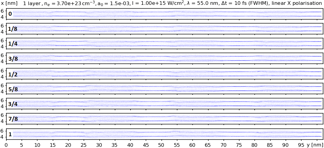
Here is an image of the electrons density, following the interaction of a plane wave (linearly polarized along the x-direction) laser with two layers of Carbon atoms. It is a 2D simulation with high resolution: about 20 mesh cells per layer. The thickness of the layer is only 0.1 nm (atom size) and the length of the sample is only 100 nm. The snapshots are along a full period at some time near the laser pulse maximum.
And here is a hand drawing of what I expect to happen.
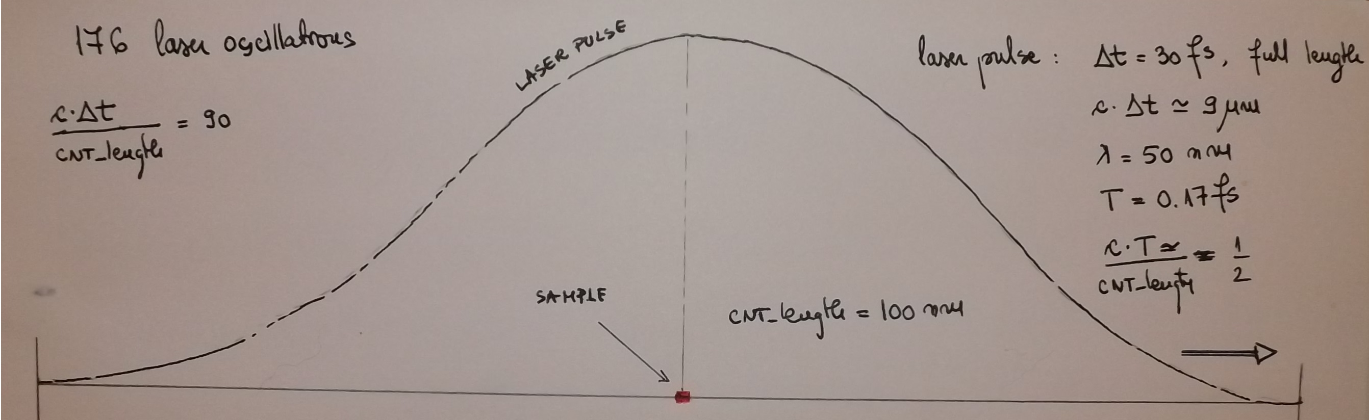
I assume that the laser pulse is entering from the left and gradually sweeps over the sample as its electric and magnetic field oscillate. The sample length is about 2 laser wavelenths long and I would expect all of it to be affected by the laser, as it moves from left to right. I can notice the up-down oscillations of the electrons and the .
However, I notice regions which are not affected at all or affected very little: y = 25 nm, y = 45 nm, y = 75 nm and y = 100 nm. This is a hint to me that the laser works somehow like a fixed string wich allows a sinusoidal oscillation with fixed zero points (along y-axis). But I expected a travelling sinusoildal oscillation.
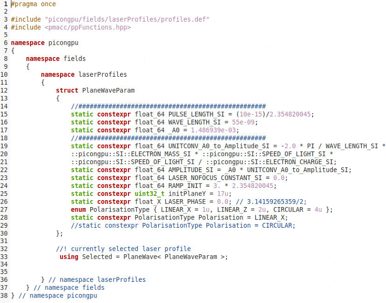
Could you please advice me if I might be doing something wrong in my laser.param file, shown as a snapshot below?
Thank you
Cristian
 cbontoiu
All 21 comments
Hello @cbontoiu . I can have a look at this question tomorrow.
 sbastrakov
on 19 Oct 2020
sbastrakov
on 19 Oct 2020
@PrometheusPi could you have a look to this question.
 psychocoderHPC
on 20 Oct 2020
psychocoderHPC
on 20 Oct 2020
I think your understanding of how the laser should work is correct @cbontoiu . PlaneWave laser in PIConGPU should generate a wave travelling along the positive direction of the Y axis, that oscillates in that direction (so travelling, not fixed zero points) and has a Gaussian temporal envelope.
So from this point there should be no issue. What is your delta_y value? Also, do you take into account that there is a laser "delay" (how far away from the center do we start) controlled by RAMP_INIT? Perhaps if you attached the whole set of .param files and the .cfg file that would provide more information.
sbastrakov
on 20 Oct 2020
@psychocoderHPC Yes, I will have a look at this. @cbontoiu Sorry for the delay, I was not in the office the last couple days.
 PrometheusPi
on 26 Oct 2020
PrometheusPi
on 26 Oct 2020
@cbontoiu You are right, the plane wave laser implementation has a propagating sinusoidal oscillation that (in vacuum and without numeric dispersion) would ravel with the speed of light, similarly to the Gaussian envelope of this laser pulse.
PrometheusPi
on 26 Oct 2020
@PrometheusPi No problem at all. I upload here the whole model. Please tell me if you spot anything that would lead to this standing-wave appearance. I know that the setup is unusual but I cannot do better with a single GPU (no moving window).
cbontoiu
on 26 Oct 2020
@cbontoiu What do you mean with "The snapshots are along a full period at some time near the laser pulse maximum."? And what do the fractions in your first plot represent (slices in time)? --> If yes, what is the total simulation time?
What boundary conditions are you using? And what is the electron density of your carbon layer?
PrometheusPi
on 26 Oct 2020
@cbontoiu Thanks for uploading your profile. I will investigate it.
PrometheusPi
on 26 Oct 2020
@cbontoiu Just the speed up the process: are you running on the current dev branch?
PrometheusPi
on 26 Oct 2020
I extracted data at 9 time moments equally spaced during a laser period. My concern is that some parts of the target seem to be less affected than other parts but the laser pulse should sweep it all. There is still the possibility that ionization happens only at the very peak of the laser pulse (due to the very low a0 = 1.5 e-03) and thus it lasts only short time and remains like a blue print further on. The results were obtained two weeks ago and I am not sure which version was. Probably the @develop version at that time.
cbontoiu
on 26 Oct 2020
@cbontoiu Please excuse the delay. I tried to compile and run your simulation based on the newest dev. After some minor fixes, it compiled fine, but I ran into a cupla (thus CUDA) error. Thus I could not reproduce your setup.
I will investigate your setup based on the param files and perhaps try to fix the cupla error.
PrometheusPi
on 11 Nov 2020
The standing wave could be caused by the reflections of the laser pulse from both "absorbing" parts of the simulation box. Since you are looking at a time, when the laser reached its peak intensity - I would have estimated with a 90% absorption, the total (multiple times reflections of the previous laser) field strength would be around 111% of the instantaneous laser field strength. Thus the significant standing wave effects you observer could not be explained by that.
However, I realized that you reduced the thickness of our absorber cells by a factor 2 but kept the absorbing strength the same as the default one. Thus I am not sure if reflection on the boundaries will be low. Assuming with this setup you only reduce reflection by 50%, you would have twice the field strength in the simulations box, and thus observe a standing wave.
Could you please plot E_x for the above plots as well. This could validate this guess.
As a solution:
To avoid reflections, please change the field solver from Yee to YeePML. This significantly reduces the influence of reflections.
PrometheusPi
on 11 Nov 2020
Hello @PrometheusPi
I will try to plot Ex for those images. Thank you for your great suggestions. I also think that the moving window should eliminate that standing wave behaviour. I must add the my a0 was incredibly small (1.5e-03) to avoid complete carbon ionization so it might just happened that ionization was possible at the very peak of the laser pulse, not before and not after, and thus the electrons were displaced only in the laser absolute maximum regions.
Now, I guess the pml.param file cannot be accepted by version 0.4.3 so I will rely on my grid.param file, which looks as shown below. For my latest 3D, model I have around 34-38 cells clearance at X, Y and Z edges so this should be fine since the absorber is spread along 32 cells, but I am not sure whether the absorbing power 1e-03 would be suitable (it was recommended like this).
In the model which started this issue (a different and 2D model) there was actually no absorber at the X and edge, because the periodicity would disable it anyway, but I can get rid of periodicity. Or is it a kind of numerical boundary condition to ensure symmetry of the solution?
#pragma once
namespace picongpu
{
    constexpr double ABSPOW = 1.00e-03;
    constexpr uint32_t ABSCELLS = 32;

    namespace SI
    {
        constexpr uint32_t CELLSX = 360;
        constexpr uint32_t CELLSY = 224;
        constexpr uint32_t CELLSZ = 416;
        constexpr double SIDEX = 3.500e-07;
        constexpr double SIDEY = 2.200e-07;
        constexpr double SIDEZ = 4.000e-07;
        constexpr float_64 CELL_WIDTH_SI  = SIDEX/CELLSX;
        constexpr float_64 CELL_HEIGHT_SI = SIDEY/CELLSY;
        constexpr float_64 CELL_DEPTH_SI  = SIDEZ/CELLSZ;
        constexpr float_64 DELTA_T_SI = 1.871450283e-18;
    } // end of SI namespace

    // Defines the size of the absorbing zone (in cells)
    constexpr uint32_t ABSORBER_CELLS[3][2] = {{ABSCELLS, ABSCELLS},{ABSCELLS, ABSCELLS},{ABSCELLS, ABSCELLS}};
     // Defines the strength of the absorber for any direction
    float_X ABSORBER_STRENGTH[3][2] = {{ABSPOW, ABSPOW}, {ABSPOW, ABSPOW}, {ABSPOW, ABSPOW}};
    constexpr uint32_t ABSORBER_FADE_IN_STEPS = 32;
    constexpr float_64 movePoint = 0.90;

} // end of picongpu namespace
@cbontoiu Thanks for providing the details. If you have periodic boundary conditions transversely (as in the above 2D example), you do not need extra cells in x and z- direction. But you should ensure there are enough cells in the y direction border region.
Furthermore, if I consider your 2D laser implantation, please also move the init plain further in. It was set to 16 cells, which now would be inside the absorber.
Additionally, I underestimated the influence of the reflected laser. In our laser implementation, we only set the electric field. Thus we initialize "2 counter-propagating" lasers, the effect thus should be 122% for 0.9 absorption and 300% for 0.5 absorption.
PrometheusPi
on 12 Nov 2020
Hello @PrometheusPi Now that I have version develop up and running I am trying to resume this issue and for this i need to run an older mode which was compiled and run with different CUDA and possibly different gcc. i get the error shown below at compilation. There must be some memory of old compilation somehwere. Of course I deleted the .build folder and there is no include\alpaka folder to delete. Do you have an idea how to solve this error in order to avoid me having to modify the typical LWFA folder to reach the model that i have now? Thank you.
[32mbuild directory:[0m .build
[32mcmake command:[0m cmake -DCMAKE_INSTALL_PREFIX=.. -DPIC_EXTENSION_PATH=.. -DALPAKA_ACC_GPU_CUDA_ENABLE=ON -DALPAKA_ACC_GPU_CUDA_ONLY_MODE=ON -DALPAKA_CUDA_ARCH="75" /home/cristian/src/spack/opt/spack/linux-linuxmint19-westmere/gcc-7.5.0/picongpu-develop-urab7eepyq34niwffc67tvicaxsp4nar/include/picongpu
-- Found Boost 1.70.0 at /home/cristian/src/spack/opt/spack/linux-linuxmint19-westmere/gcc-7.5.0/boost-1.70.0-ku6ju5y3bgt7wz5b7n5evjyxmxgjm4nl/lib/cmake/Boost-1.70.0
-- Requested configuration: QUIET REQUIRED OPTIONAL_COMPONENTS fiber
-- Found boost_headers 1.70.0 at /home/cristian/src/spack/opt/spack/linux-linuxmint19-westmere/gcc-7.5.0/boost-1.70.0-ku6ju5y3bgt7wz5b7n5evjyxmxgjm4nl/lib/cmake/boost_headers-1.70.0
CUDA_TOOLKIT_ROOT_DIR not found or specified
-- Could NOT find CUDA (missing: CUDA_TOOLKIT_ROOT_DIR CUDA_NVCC_EXECUTABLE CUDA_INCLUDE_DIRS CUDA_CUDART_LIBRARY) (Required is at least version "9.0")
CMake Error at /home/cristian/src/spack/opt/spack/linux-linuxmint19-westmere/gcc-7.5.0/picongpu-develop-urab7eepyq34niwffc67tvicaxsp4nar/thirdParty/cupla/alpaka/cmake/alpakaCommon.cmake:267 (message):
Optional alpaka dependency CUDA could not be found!
Call Stack (most recent call first):
/home/cristian/src/spack/opt/spack/linux-linuxmint19-westmere/gcc-7.5.0/picongpu-develop-urab7eepyq34niwffc67tvicaxsp4nar/thirdParty/cupla/alpaka/CMakeLists.txt:77 (include)
-- Configuring incomplete, errors occurred!
See also "/home/cristian/PIC_INPUT/PICONGPU/[M]-LAYERS-2D-PLATES/LAYERS-2D-PLATES/.build/CMakeFiles/CMakeOutput.log".
See also "/home/cristian/PIC_INPUT/PICONGPU/[M]-LAYERS-2D-PLATES/LAYERS-2D-PLATES/.build/CMakeFiles/CMakeError.log".
@cbontoiu it may be that the directory still "points" to PIConGPU version that was used to create it, which is no longer valid or accessible. However, I do not see an issue with replicating the setup for your current, functioning version of PIConGPU. To do so, you could just
- in a fresh terminal activate the environment as usual
- create an empty setup, e.g. with
pic-create $PIC_EXAMPLES/Empty [new_setup_directory] - then copy all .param files from
[old_setup_directory]/include/picongpu/param/into[new_setup_directory]/include/picongpu/param/and copy .cfg files you need from[old_setup_directory]/etc/picongpu/into[new_setup_directory]/etc/picongpu/
sbastrakov
on 16 Nov 2020
Hello,
This is for a different setup, but still about the laser.
Here I use for the laser static constexpr uint32_t initPlaneY = 33u; and for the grid there are 32 border cells at the y-axis limits and periodicity for the x- and z- directions as TBG_periodic="--periodic 1 0 1".
However there are only 24 cells between the left y-limit of the simulation domain so the laser is not initialized in vacuum. But, it seems that the plane wave laser splits in two waves. Is this what you expect, numerically?
cbontoiu
on 16 Nov 2020
It is actually another problem here because splitting in two occurs even when laser is initialized in vacuum.

cbontoiu
on 16 Nov 2020
Yes, the splitting is expected due to the way we initialize a laser. The idea is that on the right (positive Y) side of the initialization plane (Y = const) the laser is correct, and it is a combination of the right-propagating part and the reflection of the left-propagating part from the Y = Y_min boundary. For a user it means that field values between planes Y = 0 and Y = Y_laser_initialization_plane (set as a parameter of a laser, can be 0 or non-zero) are not physical. But for Y > Y_laser_initialization_plane they should be.
sbastrakov
on 17 Nov 2020
I see that the LWFA model has the laser initialized at y = 0 as static constexpr uint32_t initPlaneY = 0; and doesn't use PML. It uses 32 aborber cells alon y and the Yee solver, not YeePML Is this the recommended way?
cbontoiu
on 17 Nov 2020
You are free to choose between Yee solver + exponential absorber (how LWFA is set) or YeePML solver. The latter should generally be better. In this case, PML thickness is controlled by another file pml.param, but default values should be good enough.
However, the laser works the same way with both types of absorber
sbastrakov
on 17 Nov 2020
Related issues
 hightower8083
·
4Comments
hightower8083
·
4Comments
 ax3l
·
3Comments
psychocoderHPC
·
4Comments
ax3l
·
4Comments
ax3l
·
4Comments
ax3l
·
3Comments
psychocoderHPC
·
4Comments
ax3l
·
4Comments
ax3l
·
4Comments
Most helpful comment
@cbontoiu it may be that the directory still "points" to PIConGPU version that was used to create it, which is no longer valid or accessible. However, I do not see an issue with replicating the setup for your current, functioning version of PIConGPU. To do so, you could just
pic-create $PIC_EXAMPLES/Empty [new_setup_directory][old_setup_directory]/include/picongpu/param/into[new_setup_directory]/include/picongpu/param/and copy .cfg files you need from[old_setup_directory]/etc/picongpu/into[new_setup_directory]/etc/picongpu/