Marlin: [BUG] Junction Deviation (enabled) causes curve stuttering
Bug Description
Curved extrusions stutter (multiple full stops in the middle of a continuous curve) with Junction Deviation enabled. Enabling/Disabling S Curve and Linear Advance (indepentently and in combination) does not remedy the problem. Adjustments to acceleration and junction deviation value do not remedy the problem.
Disabling Junction Deviation remedies the problem, even with S Curve and Linear Advance both set.
My Configurations
Required: Please include a ZIP file containing your Configuration.h and Configuration_adv.h files.
Working_configs.zip
Stutter_configs.zip
Expected behavior: Smooth curve motion, as expected based on baseline experience.
Actual behavior: Stutter/halting during curve motion.
Additional Information
Configs and example video attached.
 hrabbot
All 138 comments
Could you isolate a half/full circle of the gcode that stutters, and upload it?
 qwewer0
on 8 May 2020
qwewer0
on 8 May 2020
Could you isolate a half/full circle of the gcode that stutters, and upload it?
Here's a snippet:
G1 X221.745 Y15.794 E9.0641
G1 X221.904 Y15.798 E0.0099
G1 X222.890 Y15.846 E0.0615
G1 X223.207 Y15.877 E0.0198
G1 X224.262 Y16.034 E0.0664
G1 X224.574 Y16.096 E0.0198
G1 X225.580 Y16.348 E0.0647
G1 X225.876 Y16.437 E0.0193
G1 X226.904 Y16.802 E0.0679
G1 X227.207 Y16.927 E0.0204
G1 X228.176 Y17.385 E0.0668
G1 X228.457 Y17.536 E0.0199
G1 X229.373 Y18.086 E0.0666
G1 X229.641 Y18.265 E0.0201
G1 X230.505 Y18.908 E0.0671
G1 X230.747 Y19.107 E0.0195
G1 X231.519 Y19.807 E0.0650
G1 X231.743 Y20.030 E0.0197
G1 X232.454 Y20.814 E0.0660
G1 X232.655 Y21.059 E0.0197
G1 X233.296 Y21.921 E0.0669
G1 X233.476 Y22.190 E0.0202
G1 X234.032 Y23.118 E0.0674
G1 X234.181 Y23.398 E0.0198
G1 X234.633 Y24.355 E0.0659
G1 X234.754 Y24.647 E0.0197
G1 X235.112 Y25.646 E0.0661
G1 X235.205 Y25.954 E0.0201
G1 X235.467 Y27.006 E0.0675
G1 X235.528 Y27.314 E0.0196
G1 X235.682 Y28.352 E0.0654
G1 X235.713 Y28.669 E0.0198
G1 X235.762 Y29.654 E0.0614
G1 X235.766 Y29.813 E0.0099
hrabbot
on 8 May 2020
How fast did you print?
qwewer0
on 8 May 2020
Can't really feel stutter in the given gcode snippet, or Can feel it a little stutter all the time.
Try it out: JD_single_arc_test_2.zip
qwewer0
on 8 May 2020
Gcode: Issue_17920.zip
Speed limit profile (not accounting for nominal_speed_sqr) should look roughly like this:

(JD 0.013, accel 500, as per OPs config)
The problem is, that we're just on the verge of 1 mm length on those segments. So we jump between regular >1 mm v_max_junction_sqr (white background)) and the <1 mm case limit_sqr (grey background).
EDITED: Realized, that the segment length is the problem, not the junction angle (that's around 177.5° for most).
 XDA-Bam
on 8 May 2020
XDA-Bam
on 8 May 2020
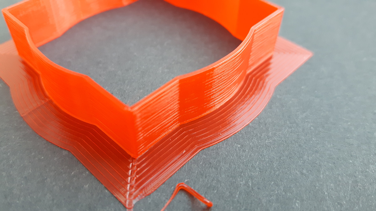
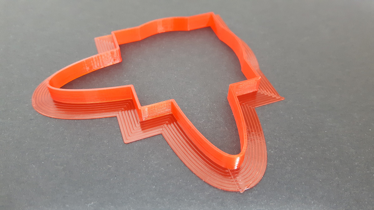
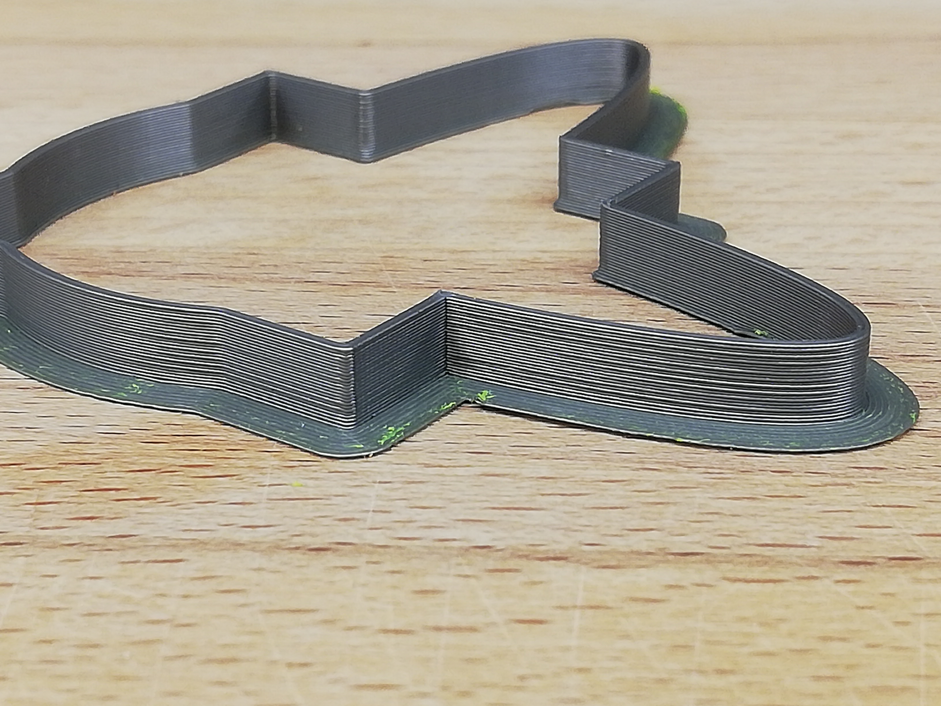
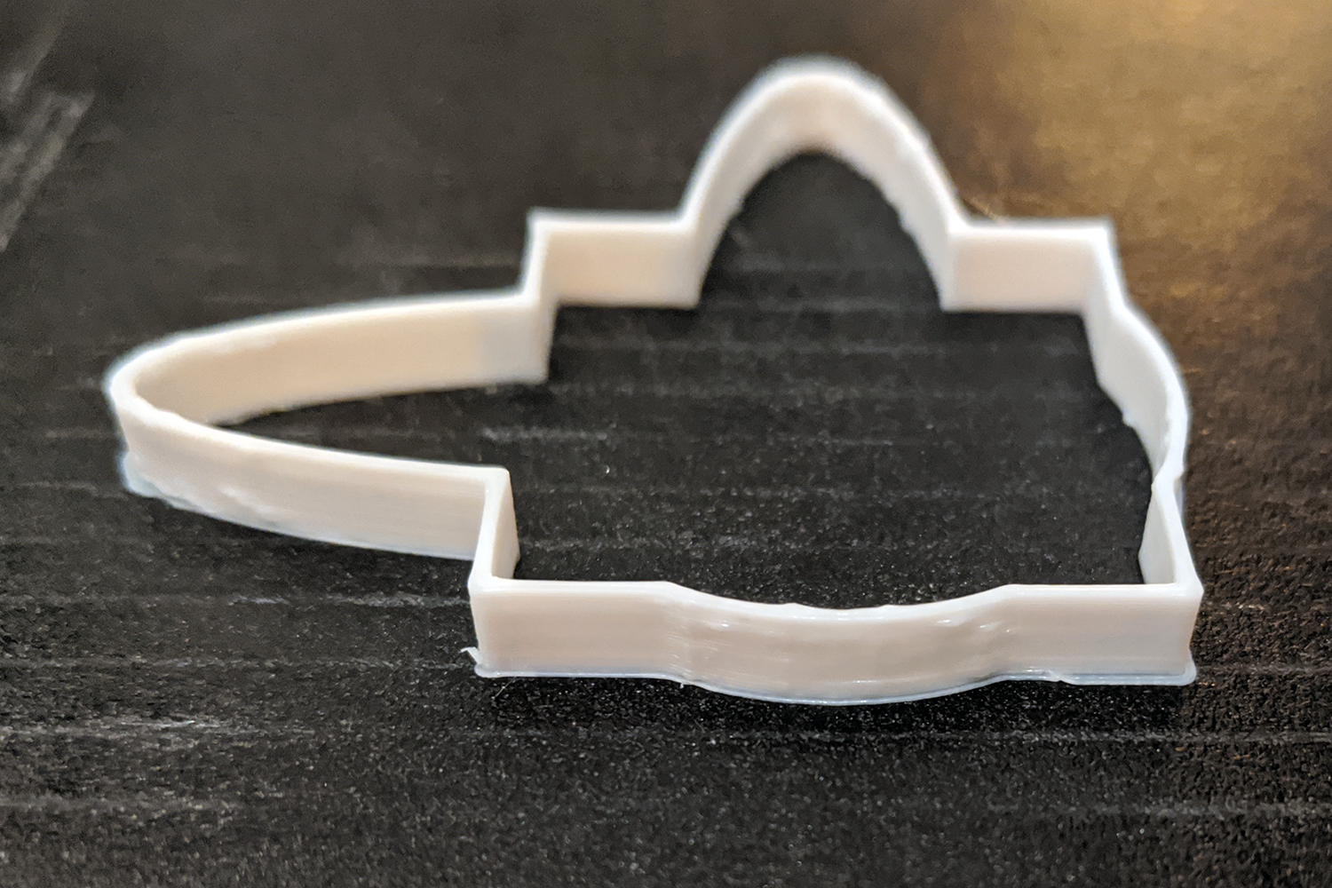
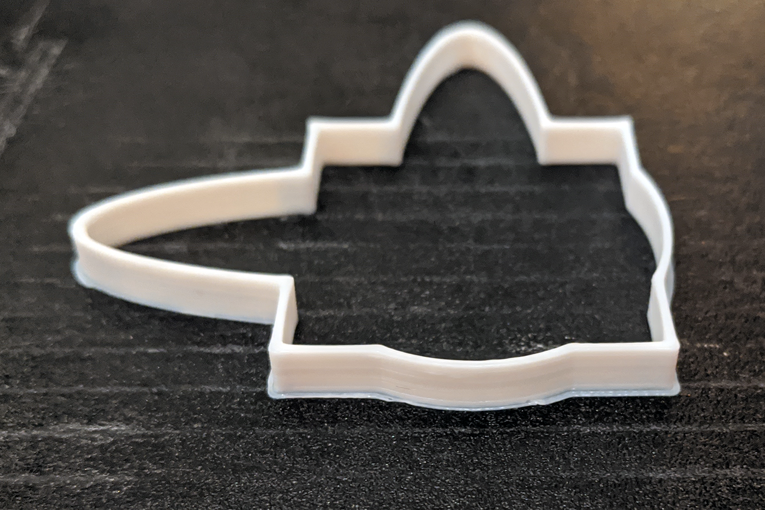
See zipped video example. Also note blobby curves already on printbed.
stutter.zip
hrabbot
on 8 May 2020
So we should come up with solution where transition between speeds will be smooth. What about get rid of 1mm block and >135° condition and do the math always? Maybe we can do it with another/faster approximation and without division at the end of calculation (I have this approximation on my github). But I'm just guessing - I don't understand the code and movement enough.
 daleckystepan
on 8 May 2020
daleckystepan
on 8 May 2020
Here's the block or segment length for the GCode in discussion:

XDA-Bam
on 9 May 2020
So we should come up with solution where transition between speeds will be smooth. What about get rid of 1mm block and >135° condition and do the math always? ...
Dropping those if-checks sadly doesn't solve the stutter in this case. limit_sqr is bumpy itself, as you can see from the speed limit plot.
This is a general problem of the discretization and the fact that we can't look ahead. The two JD code paths (>135° && < 1 mm vs. <135° || > 1 mm) have different problems due to this, but in essence, the code is "right" in stuttering like it does. The GCode is sliced in a way, which dictates these speed changes. From the point of view of the planner, it is logically impossible to tell if this one small element it is looking at right now with that slightly larger change in angle than the one before is the beginning of a sharper curve, or just a slicer artifact inside of a smooth, continous circle. No amount of transition between the two code paths can solve this problem (in general, it might work for specific cases).
There's only one way to safely prevent this: When planning a block, look ahead a couple of blocks to see where we are going. Then, fit an analytical function to our path (backwards and ahead) and calculate the second derivative for the block currently being planned. That would require extensive changes to the planner code and quite a bit of computational resources when running. Also, I wouldn't know how to implement this in C++ 😄
XDA-Bam
on 9 May 2020
Should we revert back to classic jerk before the next release?
 thisiskeithb
on 9 May 2020
thisiskeithb
on 9 May 2020
I'm not sure if it is necessary to default back to classic jerk since for the most part JD is seems to work.
Going from 5.0.5.3 and then looking at each commit I was able to determine that the problem was introduced with commit 2020.05.04 and I believe this could be the culprit: https://github.com/MarlinFirmware/Marlin/commit/c55475e8e7c7b389b30ca1d154618d73faba52ab
Below my results with the jump from good to bad:

Edit: Corrected the commit dates.
 Lord-Quake
on 10 May 2020
Lord-Quake
on 10 May 2020
Should we revert back to classic jerk before the next release?
It's preferable for many cases, so it might be the best choice for certain example configurations. However, this kind of suggestion implies that we are no closer to a solution.
Since jerk is relatively inexpensive, perhaps the best thing would be a hybrid approach.
Although, I am still curious to see if the "angular change within X total distance" accumulator approach could also work, insofar as it can be tracked in an efficient way.
I feel I could get pretty far with this sort of algorithm experimentation if I had nothing else to do. I mean, what we ultimately want to do is produce the ideal and perfect, but horribly expensive version first. Then try to chop that up into something simpler.
But maybe Classic Jerk is superior in every way? I can't think of too many reasons to fault it.
 thinkyhead
on 10 May 2020
thinkyhead
on 10 May 2020
I believe this could be the culprit
@Lord-Quake — You may be right. Does it look better if you disable JD_USE_LOOKUP_TABLE (inside of planner.h)? If so then the LUT is missing something that the old approximation has "more right."
thinkyhead
on 10 May 2020
@thinkyhead Using commit 2020.05.04 I disabled
//#define JD_USE_LOOKUP_TABLE
Result is no more stuttering. The print turned out fine.
You've now got something to work with :-)
Lord-Quake
on 10 May 2020
Just for the sake of completeness I tried the latest commit https://github.com/MarlinFirmware/Marlin/commit/86c112538084f7718252966f5f9d9278c4837fb2 and disabled
//#define JD_USE_LOOKUP_TABLE
with the same result. The stuttering has stopped, print is fine.
I did find a new issue (cosmetics only though)
Lord-Quake
on 10 May 2020
Since #17938 has already been merged and might influence this, it would be nice if someone affected could check this again (with the lookup table enabled) using most recent bugfix. It may be improved, I don't think it will be fixed.
XDA-Bam
on 11 May 2020
Well testing with my Ender 3 Pro is over for now.....
Uploaded the firmware as requested.
While starting the print I touched the X-Stepper motor and got a big electric shock.
The X-axis no longer moves. Looks like the stepper driver or some component related to the X-axis is defective. I will have to get a new main board :-(
Lord-Quake
on 11 May 2020
@XDA-Bam While my Ender 3 Pro now dead atm, with which I do all my tests I decided to update my Anet A8. Since I can't compare the degree I can say the stuttering is still evident.
Maybe someone else can also report?
Lord-Quake
on 11 May 2020
Using the latest commit (1475fd312a1572e1d43978f669bce02a72f63dab) with #define JD_USE_LOOKUP_TABLE and I'm no longer observing any stuttering. If there's any it is minimal. Before the whole machine was shaking on arcs.
 lzamel
on 11 May 2020
lzamel
on 11 May 2020
By disabling JD_USE_LOOKUP_TABLE the planner is using the older JD code. The newer JD code is supposed to be more accurate and use less processing, but it also seems to produce the side effects you are seeing. We are continuing to experiment, and will do a comparison of the numbers that come out of the current code versus the older code.
thinkyhead
on 12 May 2020
@XDA-Bam While my Ender 3 Pro now dead atm, with which I do all my tests I decided to update my Anet A8. Since I can't compare the degree I can say the stuttering is still evident.
Maybe someone else can also report?
Bro if you are in the USA I have a spare stock motherboard I can send to you to get you back up. I used bugfix for a day and a half before I realized JD was ruining my prints.
 cwizard
on 14 May 2020
cwizard
on 14 May 2020
@cwizard Thanks for the offer! I'm in Germany and will try to get a replacement.
Lord-Quake
on 14 May 2020
Hi, where I can comment on the function JD_USE_LOOKUP_TABLE? I have CONFIGURATION_H_VERSION 020005 and I have the same problem with motion stutter.
Thank you for answer
 davevo22
on 16 May 2020
davevo22
on 16 May 2020
@davevo22
\Marlin\src\module\planner.h
Lord-Quake
on 16 May 2020
I searched there but did not find it. Row number?
davevo22
on 16 May 2020
Around line 43
Lord-Quake
on 16 May 2020
interesting but this function is not there: D
davevo22
on 16 May 2020
hear is all code https://pastebin.pl/view/9138260a
davevo22
on 16 May 2020
It's in the latest commits. You are most likely using an older version of Marlin.
Lord-Quake
on 16 May 2020
Im using last stable version 2.0.5.3
davevo22
on 16 May 2020
Oh, in that case you won't find it.
Stay with 2.0.5.3 unless you have problems that might have been fixed in the latest bugfix version.
Lord-Quake
on 16 May 2020
I currently see two possible reasons for the stutter:
- There's a bug in the LUT or the code is compiled incorrectly.
- The higher precision and valid range of
junction_thetafrom the LUT is screwing with something else.
I'd ilke to check number 2 and made a quick edit to planner.cpp, limiting the range of junction_theta to the one we get out of the Minimax poly: 2020-05-16_planner_fix_1.zip
The only change to current bugfix is the line NOLESS(junction_theta, RADIANS(180 - 178.11));, but feel free to check yourself.
To those affected: Please test, if this reduces the stutter to a similar level as when using the polynomial approx. Please make sure to enable the LUT by uncommenting #define JD_USE_LOOKUP_TABLE in planner.h. If unsure, just download the latest bugfix-2.0.x and just copy over the replacement planner.cpp.
XDA-Bam
on 16 May 2020
@XDA-Bam It feels worse, with a larger bump at the small segments.
qwewer0
on 16 May 2020
None of the variants can be compiled. :((((
davevo22
on 16 May 2020
None of the variants can be compiled. :((((
With the latest bugfix?
qwewer0
on 16 May 2020
davevo22
on 16 May 2020
Just that planner.cpp, or all the bugfix?
qwewer0
on 16 May 2020
only planner.cpp
davevo22
on 16 May 2020
only planner.cpp
You need to use the whole bugfix marlin.
qwewer0
on 16 May 2020
@Lord-Quake How about your A8? Does the modified planner.cpp make any difference concerning the stutter?
@davevo22 You need the whole bugfix-2.0.x package. Then, overwrite the original planner.cpp with the provided file.
XDA-Bam
on 17 May 2020
@XDA-Bam
Normally I don't touch the only printer I have left as it needs to be working.
However, if I do test with the A8 what commit do you want me to use?
Lord-Quake
on 18 May 2020
If the machine is critical to you, it's probably better not to test some random experimental build on it. We can wait a couple of days until someone else checks it or your replacement board arrives.
XDA-Bam
on 18 May 2020
Still, what commit would you want me to use?
Lord-Quake
on 18 May 2020
847bdee would be good.
XDA-Bam
on 18 May 2020
@XDA-Bam I did the test with the above commit on my A8 and used the same gcode file as with my Ender 3.
The curved stuttering was not present and the print surfaces be it flat or curved are all same in quality.
Lord-Quake
on 18 May 2020
OK, so conflicting results.
@Lord-Quake and @qwewer0 Just to make sure: You both ran this test, using the updated planner.cpp with #define JD_USE_LOOKUP_TABLE still enabled, right? So, using the LUT?
XDA-Bam
on 18 May 2020
I'm including my configs to eliminate any misunderstandings :-)
Lord-Quake
on 18 May 2020
Yes, using the planner.cpp and with #define JD_USE_LOOKUP_TABLE enabled.
Edit: Latest Bugfix-2.0.x
qwewer0
on 18 May 2020
Well, that's just... 🐳 Am I correctly assuming, that the Anet A8 is running some form of ATMega, while @qwewer0 is running an STM32F103 chip?
XDA-Bam
on 18 May 2020
I'm using "STM32F103RC_btt_512K" SKR mini 1.1
Lord-Quake
on 18 May 2020
Mine is an STM32F103 RCT6.
Edit:
To avoid confusion, this is what I did when try to test JD:
- Using my configuration files (JD enabled) and the necessary JD test files (e.g. planner.h, planner.cpp) I compile the latest Bugfix-2.0.x marlin and flash it on my SKR Mini E3 v1.2 board
- After flashing the new firmware to the board, I recheck the JD, Acc, etc. values
- I test it with JD_single_arc_test.gcode and this gcode
- I place one hand on the heated bed and the other on the hotend carriage to feel the movements of the axes
- So far I felt the bump/stutter/slow down about the middle of the curve, but more precisely, where the small segments are located
Edit: added this issues gcode, as I test that too.
qwewer0
on 18 May 2020
Thanks for clarifying. Did both of you use the GCode from this issue, or maybe the JD_single_arc_test.gcode?
XDA-Bam
on 18 May 2020
As an isolation test, please try JD with bed leveling disabled to see if it exhibits the same stuttering when there is no Z compensation.
thinkyhead
on 18 May 2020
@XDA-Bam Will try the gcode from this issue.
@thinkyhead will M420 S0 do it?
qwewer0
on 18 May 2020
Yes, as long as the system is off, it should be good. But, feel free to also try fully disabling to see if it has any effect. It's another layer in the planner, after all.
thinkyhead
on 18 May 2020
Bugfix with bed leveling off in firmware:
1. With changes to the planner:
- JD_single_arc_test.gcode -> Maybe slightly better, lighter bump/stutter than without the changes to the planner, but it is really hard to tell. Could be placebo.
- This issues gcode -> Feels the same as without the changes to the planner, but now I can feel a hard bump/slow down around at the end of the curve.
2. Without changes to the planner:
- JD_single_arc_test.gcode -> Feels the same as before. Stutter at the small segments.
- This issues gcode -> Continuous stutter, that is really hard to feel, almost nothing.
My bad, wrong planner test.
qwewer0
on 18 May 2020
OK, sorry, but you're starting to mix things (or I'm confused). Please disregard the fresh PR #18031 for now - or report about testing it in the PR itself. I encourage your enthusiasm, but it's important to look at the issues and possible fixes one by one.
For now, my main question is, if the small change in planner.cpp has any effect on the GCode of this issue, running bugfix around 847bdee. The effect of bed leveling can also be checked, but seperate.
XDA-Bam
on 19 May 2020
@XDA-Bam Did you check my configs to make sure I have the settings are correct?
Here is the result using the settings I provided above and https://github.com/MarlinFirmware/Marlin/commit/847bdeecafd14ea611af0bda723ebe99c8d2d29b:
This is printed in vase mode with "AUTO_BED_LEVELING_BILINEAR". As far as I can see the lines and the radius are clean (brim slow speed and object high speed print).
PS: What I don't like is that the layers aren't uniform but I believe that is different issue. Could be hardware related or printing too fast at least compared the my Ender 3 where layer to layer is very clean.
I'm enclosing the stl file for comparison prints:
Cube_40mm.zip
Lord-Quake
on 19 May 2020
Latest bugfix with bed leveling off in firmware:
1. With changes to the planner:
- JD_single_arc_test.gcode -> Smaller bump/stutter than without the changes to the planner
- This issues gcode -> Feels almost the same, but with softer continuous stutter
2. Without changes to the planner:
- JD_single_arc_test.gcode -> Stutter at the small segments.
- This issues gcode -> Continuous stutter, that is really hard to feel, almost nothing.
qwewer0
on 19 May 2020
@qwewer0 I'm curious to know at what point did your issue come up. Which firmware version does not produce the problems you seem to be observing.
Lord-Quake
on 19 May 2020
@XDA-Bam Did you check my configs to make sure I have the settings are correct?
Yes, concerning JD, they look like they should.
Here is the result using the settings I provided above:
This is printed in vase mode with "AUTO_BED_LEVELING_BILINEAR". As far as I can see the lines and the radius are clean (brim slow speed and object high speed print).
Looks good. So, this is with the altered planner.cpp and has no issues? And with the original 847bdee, the issues are present?
PS: What I don't like is that the layers aren't uniform but I believe that is different issue. Could be hardware related or printing too fast at least compared the my Ender 3 where layer to layer is very clean.
I'd agree that this is likely to be a hardware issue (Z binding, uneven filament diameter, etc.).
XDA-Bam
on 19 May 2020
Latest bugfix with bed leveling off in firmware:
1. [With changes to the planner](https://github.com/MarlinFirmware/Marlin/issues/17920#issuecomment-629659026):


* [JD_single_arc_test.gcode](https://github.com/MarlinFirmware/Marlin/issues/17342#issuecomment-613591471) -> Smaller bump/stutter than without the changes to the planner
That is expected, we're cutting away the upper part of the "sawtooth" speed limit profile. When printing with a fast enough nominal speed, it should feel a little less jerky.
* [This issues gcode](https://github.com/MarlinFirmware/Marlin/issues/17920#issuecomment-625989631) -> Feels almost the same, but with softer continuous stutter
Interesting.
1. Without changes to the planner:


* JD_single_arc_test.gcode -> Stutter at the small segments.

* This issues gcode -> Continuous stutter, that is really hard to feel, almost nothing.
OK. Thanks for testing again!
XDA-Bam
on 19 May 2020
@XDA-Bam My above result was done with https://github.com/MarlinFirmware/Marlin/commit/847bdeecafd14ea611af0bda723ebe99c8d2d29b as per your request.
Lord-Quake
on 19 May 2020
@qwewer0 I'm curious to know at what point did your issue come up. Which firmware version does not produce the problems you seem to be observing.
Tested:
Marlin 2.0.0:
- JD_single_arc_test.gcode -> Feels mostly the same as the latest bugfix, with bump/stutter at small segments.
- This issues gcode -> Very noticeable continuous stutter along the curve.
2.0.1:
- JD_single_arc_test.gcode -> Same or maybe a bit worse than 2.0.0, but it is hard to tell, so let's say that it feels the same.
- This issues gcode -> Same as 2.0.0.
2.0.2:
- JD_single_arc_test.gcode -> Same as 2.0.1.
- This issues gcode -> Same as 2.0.1.
2.0.3:
- JD_single_arc_test.gcode -> Same as 2.0.2.
- This issues gcode -> Same as 2.0.2.
2.0.4.4:
- JD_single_arc_test.gcode -> Same as 2.0.3.
- This issues gcode -> Same as 2.0.3.
2.0.5.3:
- JD_single_arc_test.gcode -> Same as 2.0.4.4.
- This issues gcode -> Same as 2.0.4.4.
qwewer0
on 19 May 2020
@qwewer0 Thanks for the details. I've never had the issues with the versions you have listed.
I'm also starting to ask myself if the issue you are seeing and the work from XDA-Bam are two different items. For my part using the latest commit I no longer have the stuttering that I had documented 9 days ago with a previous commit.
Lord-Quake
on 19 May 2020
This is difficult to diagnose, since it depends on many factors. For example, printing with lower nominal speed should eradicate the stuttering, because the limits set by JD should not come into play when you print at 40 or 50 mm/s. But when printing at 80 or 100 mm/s, it could still pop up. Then there's different machines, different processor architectures and all that. Also, this is affected by the slicer - I suspect that it is basically a slicer bug, somewhat amplified by how Marlin handles direction changes.
@Lord-Quake Could the fact that the issue is gone for you now be related to you switching from the Ender to the A8?
XDA-Bam
on 19 May 2020
No, I don't believe so. I'm using SKR boards on both printers. My test object is the same and I'm using the same Gcode on both printers. As slicer I'm using Cura_SteamEngine 15.01, very old and fundamental.
Anyhow, shout if you want me to do a test.
Lord-Quake
on 19 May 2020
Out of curiosity, I checked commits to the relevant files in the last 10 days.
planner.cpp:
- 181739d: laser stuff
- c2d66a5: cosmetic change
- 8a22ef0: direct stepping feature
- 3381a4a: JD vector normalization fix, small slow-down - affects non-travel moves on non-CoreXY machines
planner.h:
- 181739d: laser stuff
- 8a22ef0: direct stepping feature
- e22e076: small JD speed-up
If I had to bet, I'd say the issue will still be present for you in fcd1678a and fixed with 3381a4a. As 3381a4a only affects print moves, it would explain why @qwewer0 does not see any difference (I'm assuming he/she is doing dry runs without extrusion). @lzamel also reported, that the problem was gone on 1475fd3, which is a couple of commits past 3381a4a.
If you are bored some time in the coming days, it would be cool if you could check if the stutter disappears between fcd1678a and 3381a4a. That is, running a real print with extrusion.
XDA-Bam
on 19 May 2020
If you are bored some time in the coming days, it would be cool if you could check if the stutter disappears between fcd1678 and 3381a4a. That is, running a real print with extrusion.
@XDA-Bam
What should I print to test it?
Pre sliced gcode or SLT?
If SLT, then with which slicer (Cura, PrusaSlicer, Simplify3D, Fusion 360, etc.) and with what settings?
qwewer0
on 19 May 2020
I will gladly do the tests. However, I've reverted back to 2.0.5.3 as I need a working printer.
I hope to get my TMC2208 chip soon and I will swap it on the board.
I modified my test STL by adding 2 elliptical sides.
Here the STL file: Cube_40mmV2.zip
As soon as my Ender 3 is back up and running I can dedicate myself to tests but I guess you will have found a solution by then ;-)
Lord-Quake
on 19 May 2020
However, I've reverted back to 2.0.5.3
If you're using JD with that version then it's using the old calculation method, labeled as "Trig half angle identity." It sounds like the old dynamics are notably smoother. I'll have to scroll back and find those graphs….
thinkyhead
on 19 May 2020
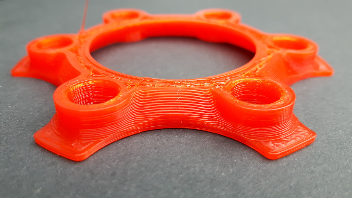
I tried to print Cube_40mmV2.stl it turned out very well. Then I released my model and it turned out terribly.
davevo22
on 19 May 2020
Then I released my model and it turned out terribly.
@XDA-Bam Could you share your file in 3mf or SLT?
qwewer0
on 19 May 2020
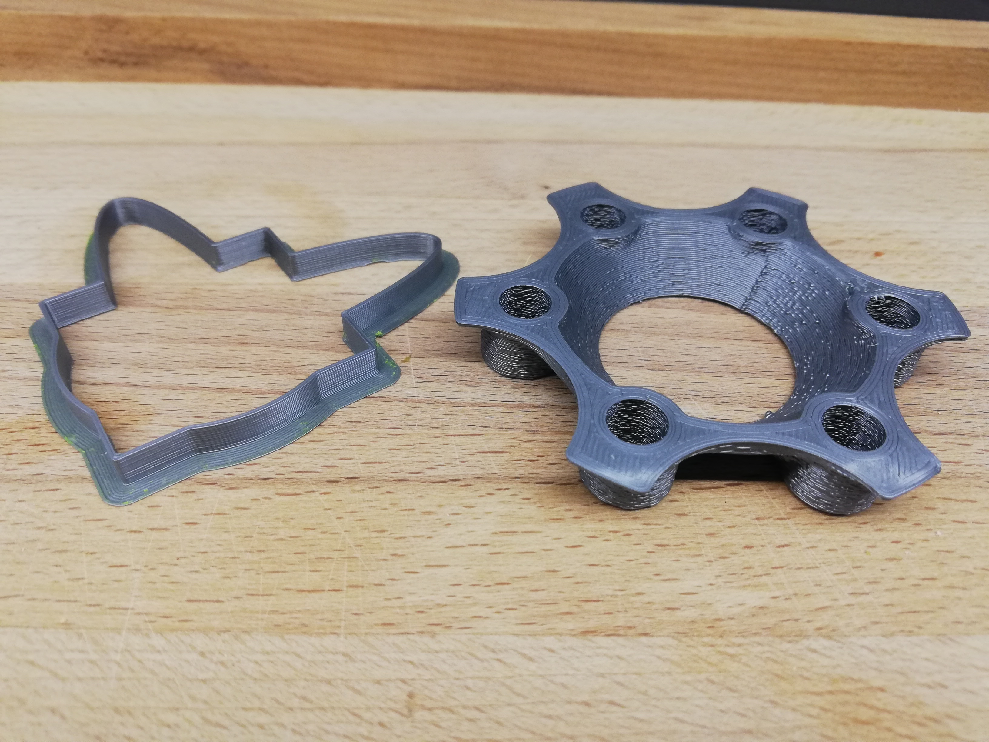
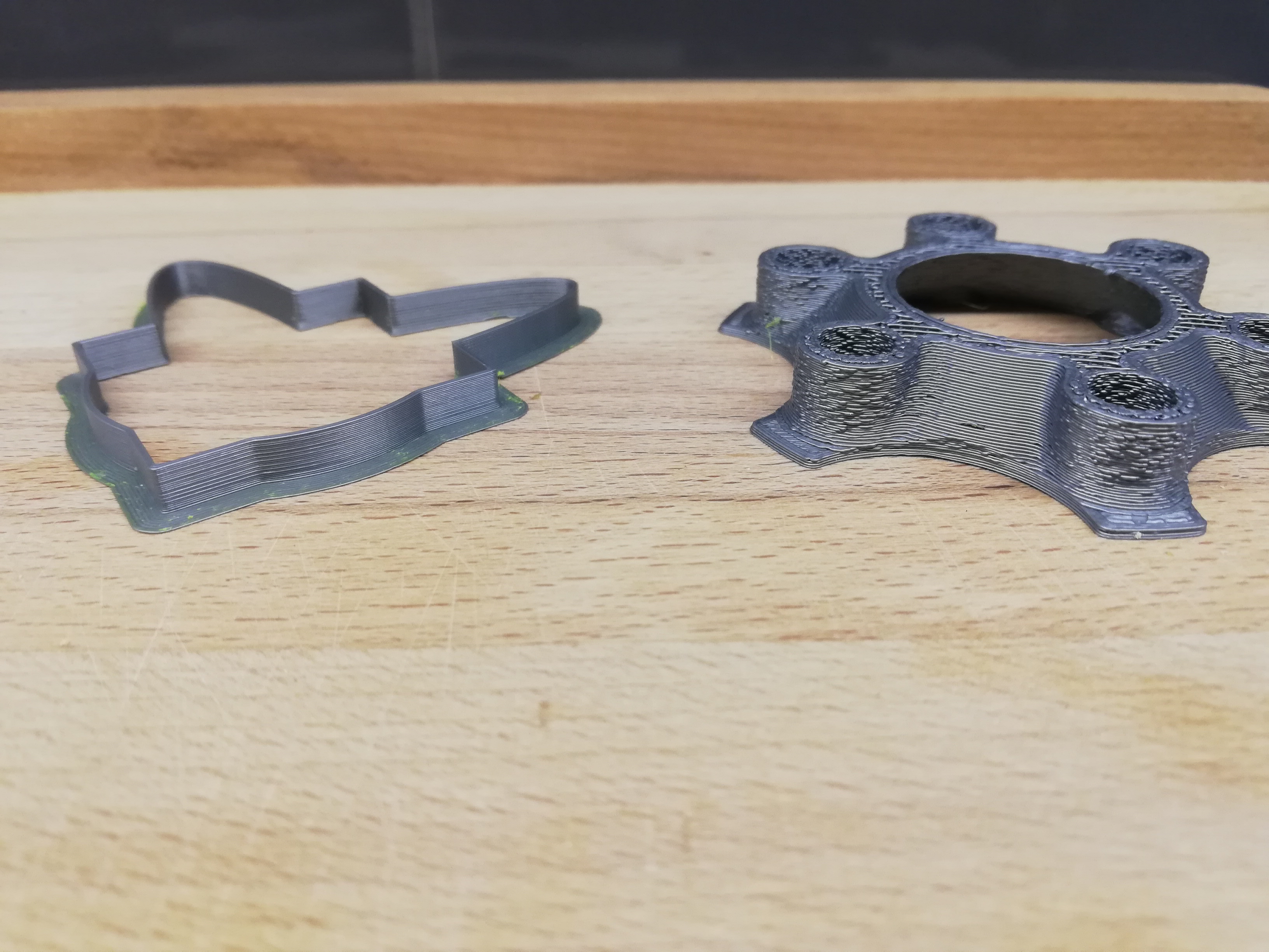
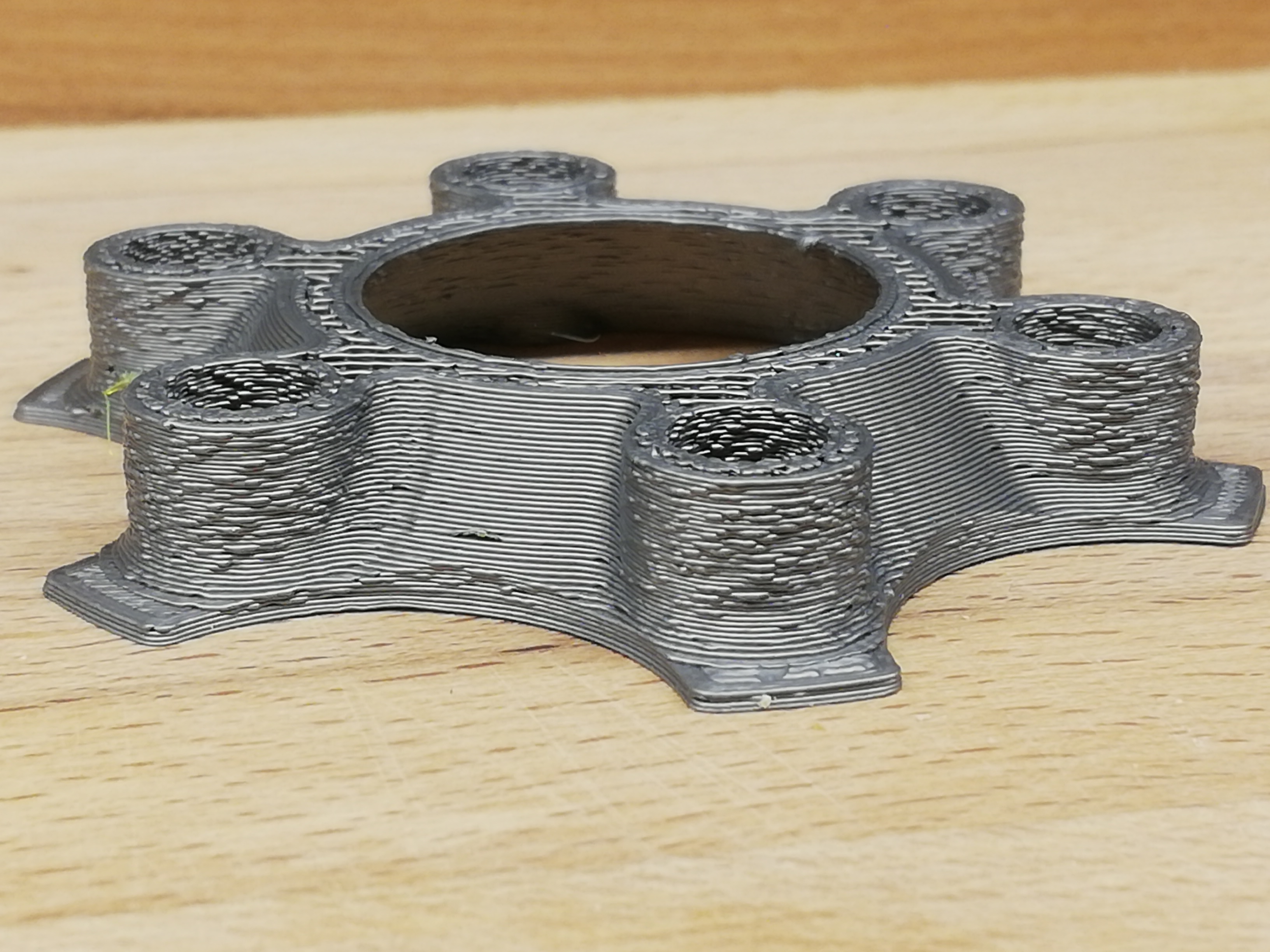
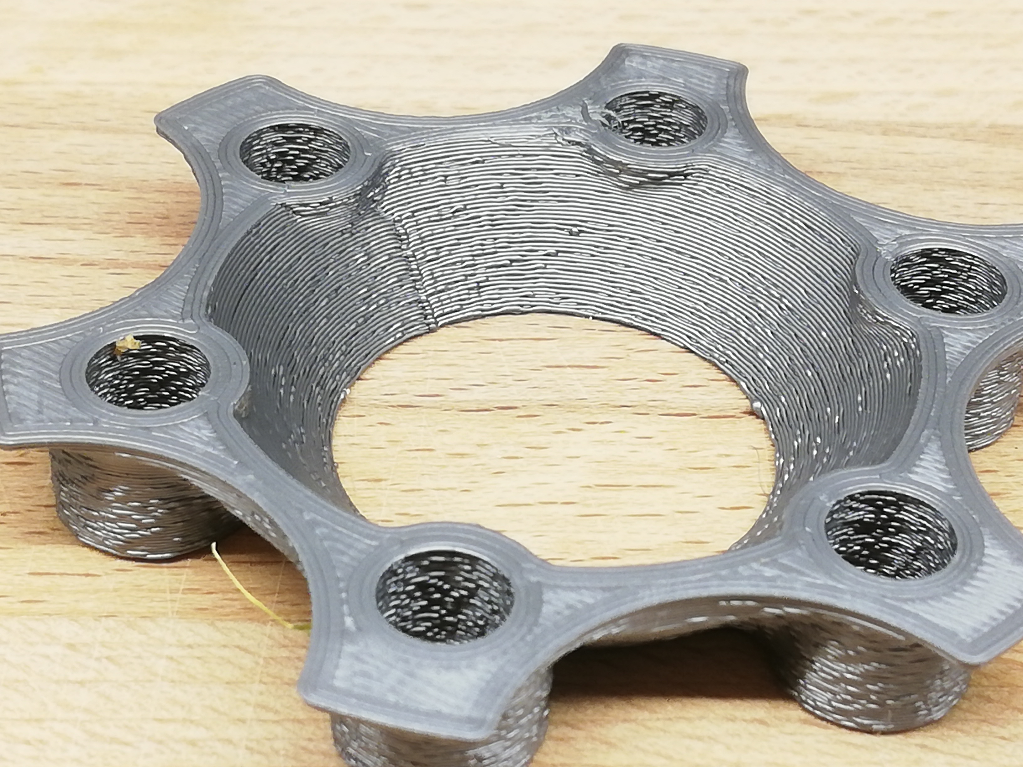
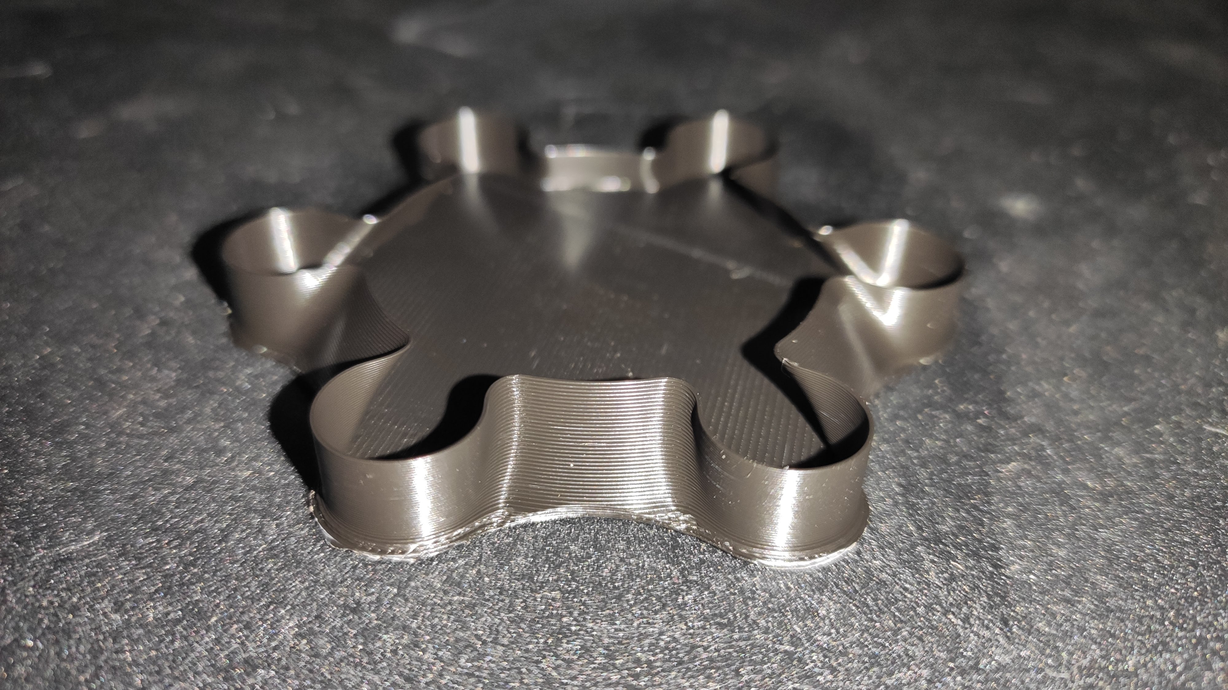
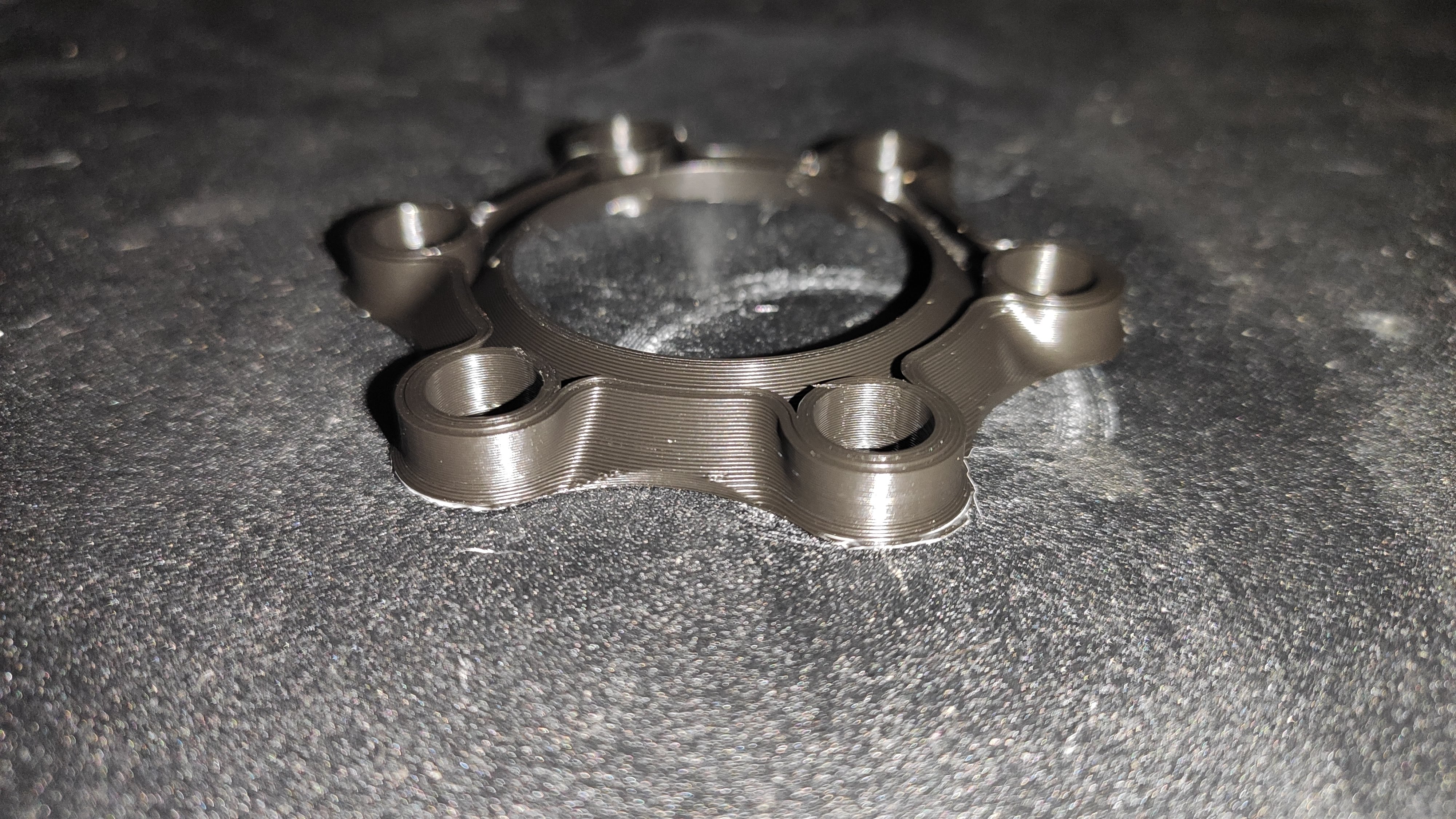
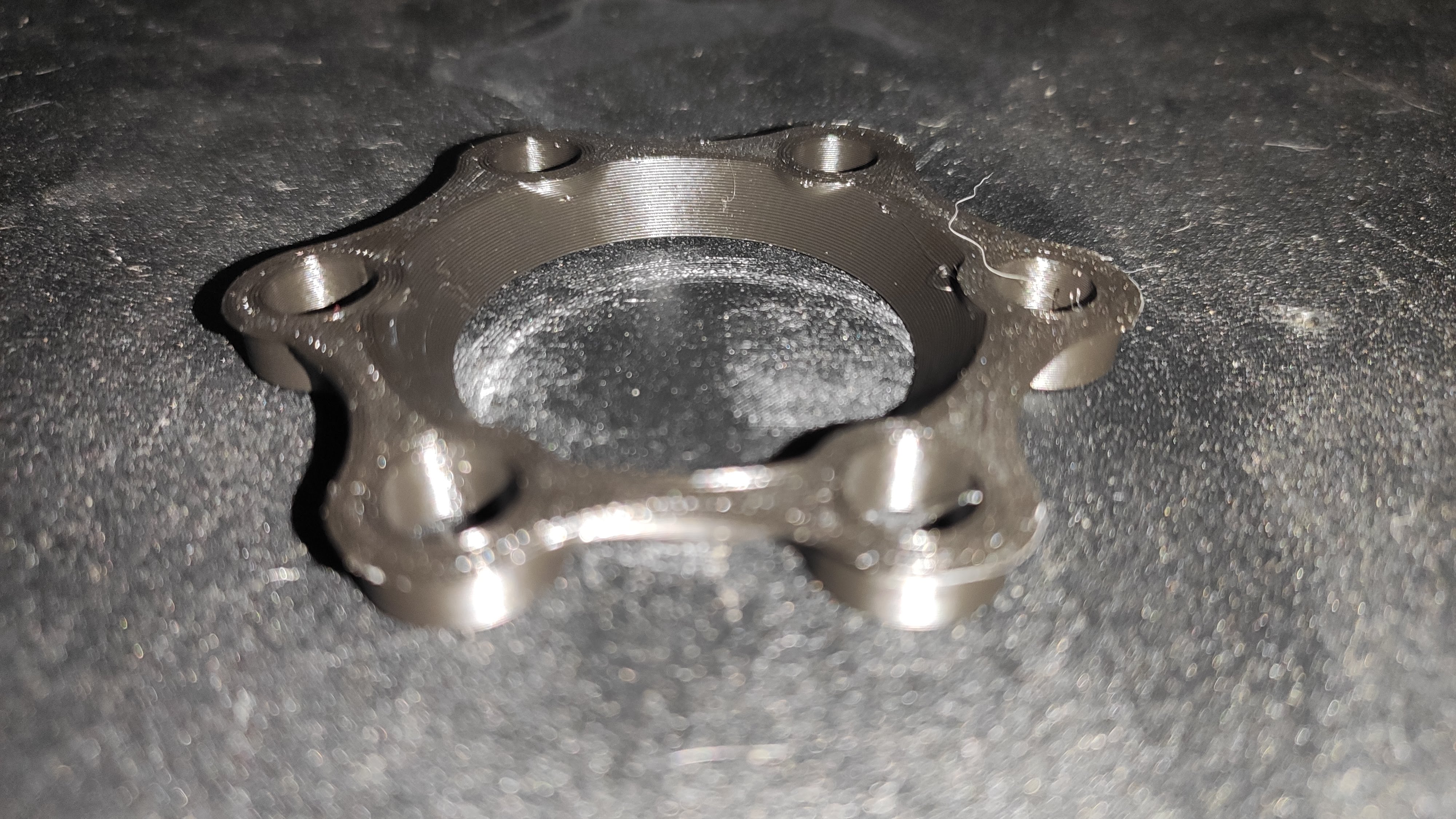
Here is mine STL
Palmiga_ORC_rim9_V1.zip
davevo22
on 20 May 2020
Here is mine STL
Palmiga_ORC_rim9_V1.zip
Which bugfix should I test it first?
qwewer0
on 20 May 2020
@davevo22
Here is my result. I stopped 55 minutes into the print.
Printed with an Anet A8 using SKR Mini V1.1 and Marlin 2.0.5.3.
Outer layer print speed was set to 30mm/s. Everything else higher....
For completeness my configs: Configuration_2.0.5.3.zip
In my opinion a nice and clean print.
Edit: There was no stuttering with this print.
Lord-Quake
on 20 May 2020
@davevo22
- What is your hardware (mainboard & processor)?
- Could your attach the Marlin configs you were using when printing the failed model?
- Did you run the cube and your model with identical slicer settings?
- Could you give us a short summary of your slicer settings for the failed model (slicer & version, nominal speed inner & outer walls, changes to acceleration and jerk in the slicer, minimal detail and resolution settings)?
XDA-Bam
on 20 May 2020
3mf files: Palmiga_ORC_rim9_V1.3mf.zip
Vase mode:
Normal mode:
Latest bugfix, PrusaSlicer 2.2.0, SKR Mini E3 v1.2, Ender 3
Settings
- 500, 1000, 750 acc.
- 15 ejerk
- 0.08 JD
- Bed leveling off in firmware
- Linear Advance ON, K=0.18
- S-Curve OFF
- 0.2 layer height
- 0.37 line width
- 50mm/s print speed everywhere
- 150mm/s travel speed
- 0% infill
- 3 perimeters
- 185°C
qwewer0
on 20 May 2020
@qwewer0 Looks great. I'd however recommend always printing with infill as it is much more demanding on the printer. E.g. layer shifts and such are much more likely to pop up.
Lord-Quake
on 20 May 2020
@qwewer0 Looks great. I'd however recommend always printing with infill as it is much more demanding on the printer. E.g. layer shifts and such are much more likely to pop up.
But we doesn't test that...
qwewer0
on 20 May 2020
True :-)
Lord-Quake
on 20 May 2020
We yet to find a model that prints bad for everyone.
qwewer0
on 20 May 2020
What is your hardware (mainboard & processor)?
SKR 1.3 with LPC1768
Could your attach the Marlin configs you were using when printing the failed model?
Marlin-2.0.5.3 config.zip
Did you run the cube and your model with identical slicer settings?
YES
Could you give us a short summary of your slicer settings for the failed model (slicer & version, nominal speed inner & outer walls, changes to acceleration and jerk in the slicer, minimal detail and resolution settings)?
PrusaSlicer 2.2.0
200,200,5,25 max speed
1200,1200,100,1000 max aceleration
perimetr 45mm/s
small perimetr 25mm/s
extra perimetr 35mm/s
2.5 ejerk
0.08mm JD
Linear Advance ON, K=0.06
S-Curve OFF
0.2 layer height
0.4 line width
150mm/s travel speed
20% infill
2 perimeters
210°C
The printer sometimes freezes completely. He writes a Printing.... on the LCD but he doesn't move
davevo22
on 20 May 2020
The printer sometimes freezes completely. He writes a Printing.... on the LCD but he doesn't move
Thank you for the detailed settings info. The freezes point to additional problems on your specific machine. Hopefully they don't interfere with testing this issue 🤞
Also: Running E-Jerk 2.5 with linear advance is way too low in my experience. If the extruder jerk is too low, linear advance will force slow-downs during printing. If you don't mind, could you perhaps test to print your failed part with an E-Jerk of 10, to see if the problems persist?
Still odd, though, that one part is perfect, while the second is junk 🤷
XDA-Bam
on 20 May 2020
I had a bit of time on my hands and quickly checked, what effect fcd1678 and 3381a4a had on any potential stutter. I used the original 40mm_Cube.stl to test this on my Ender 3 Pro using default bugfix configs for the Ender (JD on, LA & S-Curve off). Result:
- On fcd1678, the printer sounds like the f**ng woodpecker on curved parts. Everything non-curved horribly underextruded. Had to stop the print after two minutes, the result was garbage.
- On 3381a4a everything sounds fine. Result looks decent on curved and straight parts, but I stopped the print after 2 minutes, just to waste no filament. On the curved parts, the inner layers had two pronounced bumps (local overextrusion) per side. The outer layers were clean.
EDIT: Here's two videos showing both prints. Unfortunately, the sound volume is very low. So you have to crank it up quite a bit to hear the stutter - Cube_40mm_bugfix-2.0.x.zip
Also, odd enough, the LCD hung up on both prints while trying to set babysteps. But that may be fixed in the most recent bugfix - didn't check.
Conclusion: Either e22e076 or 3381a4a fixed some serious bug in JD. There seem to be more problems, though.
@davevo22 The file name in your last settings post suggests, that you used Marlin-2.0.5.3 (release) to print the Cube_40mm.stl and your Palmiga_ORC_rim9_V1.stl. Is that correct, or did you use a recent bugfix build and that is just a typo?
XDA-Bam
on 25 May 2020
I have my Ender-3 Pro up and working again. It now runs with the new SKR Mini E3 V2.0.
I installed STRING_DISTRIBUTION_DATE "2020-05-25" and my first print was to see if the stuttering is still evident which sadly it is.
Disabling JD_USE_LOOKUP_TABLE got ride of the stuttering.
Lord-Quake
on 28 May 2020
I just got the right cable and did some serial debugging running 2.0.x-bugfix @ a740b6b. I did a dry run of our trusty JD_single_arc_test.gcode and had junction_theta printed out. As a reminder, junction_theta = 180°-Theta. This is the result for the central part of that arc (junctions 30 - 40):
MATLAB [°] | Marlin LUT [°] | Marlin Minimax poly [°]
-- | -- | --
2.63 | 2.86 | 2.46
2.40 | 3.35 | 2.67
2.55 | 1.37 | 2.02
2.47 | 2.45 | 2.30
3.19 | 1.96 | 2.15
0.71 | 0.00 | 1.90
3.15 | 6.61 | 4.85
0.70 | 3.97 | 2.99
3.20 | 3.97 | 2.99
0.52 | 1.14 | 1.97
2.76 | 3.34 | 2.66
"MATLAB" shows the precise angle to be expected according to my calculations, "Marlin LUT" uses the LUT to calc 180°-Theta (#define JD_USE_LOOKUP_TABLE), "Marlin Minimax poly" uses the polynomial to calc 180°-Theta (//#define JD_USE_LOOKUP_TABLE).
The LUT results for a 15 element version like we're running should be close to identical to the MATLAB result. As you can see, that is not the case - in fact, the LUT error is all over the place and even seems to induce a divide by zero (although serial ouput only has two decimal places, so that may not be a true zero).
I also calculated precise results for the expected LUT and Minimax angles in MATLAB. Those do not agree well with the values Marlin prints out. I don't know why that is the case. I suspect that it's due to numerical errors induced by the float used in Marlin, while MATLAB uses double.
Overall, I'm not totally sure what the conclusion is, here. It looks to me like the LUT results are somewhat fishy, especially considering the zero, which might cause problems in this divide. Maybe someone with more experience could weigh in here?
XDA-Bam
on 28 May 2020
After the inconclusive test yesterday, I went back to debugging a bit more. Looking at the original junction_cos_theta Marlin is computing instead of my MATLAB values allows us to better evaluate, whether the LUT works as expected. Results for same settings, firmware and junctions as in last post are as follows:
junction_cos_theta | acos() (Excel) | LUT angle | LUT error | Minimax angle | Minimax error
-- | -- | -- | -- | -- | --
[-] | [°] | [°] | [%] | [°] | [%]
-0.998743 | 2.87 | 2.86 | -0.5 | 2.46 | -14.4
-0.998288 | 3.35 | 3.35 | -0.1 | 2.67 | -20.4
-0.999713 | 1.37 | 1.37 | -0.2 | 2.02 | 47.2
-0.999090 | 2.44 | 2.45 | 0.2 | 2.30 | -5.9
-0.999412 | 1.96 | 1.96 | -0.3 | 2.15 | 9.4
-0.999963 | 0.49 | 0.00 | -100.0 | 1.90 | 285.5
-0.993307 | 6.63 | 6.61 | -0.3 | 4.85 | -26.9
-0.997575 | 3.99 | 3.97 | -0.5 | 2.99 | -25.1
-0.997575 | 3.99 | 3.97 | -0.5 | 2.99 | -25.1
-0.999800 | 1.15 | 1.14 | -0.5 | 1.97 | 71.9
-0.998293 | 3.35 | 3.34 | -0.2 | 2.66 | -20.6
"acos() (Excel)" is the acos() of junction_cos_theta in Excel, "LUT angle" is the angle Marlin computes using #define JD_USE_LOOKUP_TABLE, "Minimax angle" is the Marlin result using //#define JD_USE_LOOKUP_TABLE.
Results show, that the LUT results are overall far better error-wise. With one exception, they are below +-0.6%, as they should be. The Minimax polynomial is far worse. The only problem is the zero value for junction_cos_theta = -0.999963: I checked it again, and it is a true zero - that should _never_ happen for junction_cos_theta != -1. There is definitely a problem in the LUT code. I don't know if that zero is the culprit of the stutter, but it results in a divide by zero and needs to be fixed. @daleckystepan could you help with this?
I also think the values of junction_cos_theta itself are problematic - they are quite far away from the precise results my MATLAB code is suggesting and the deviations result in a higher variance of junction_theta. That also results in a higher variance in junctions speeds, which might lead to (occasional) stutter. I suspect this might be difficult to diagnose, but we will see.
XDA-Bam
on 29 May 2020
@XDA-Bam I will look at it over the weekend.
daleckystepan
on 29 May 2020
Just as a heads up: I replicated the LUT code in MATLAB as close as I could. This introduces a potential source for "translation" errors, but MATLAB makes it much easier for me to debug. I'm getting an "array out of bounds" (index is one higher than array size) for acos(-0.99994), while acos(-0.99993) runs fine. At first sight, that behaviour is consistent with the serial output shown yesterday, where only -0.99996 produced an error.
XDA-Bam
on 30 May 2020
OK, so I am not 100% sure, but I think the following happens: If junction_cos_theta is below -(1-1/2^15) = -0.99997, the inner part (1.0f - t) * jd_lut_tll in https://github.com/MarlinFirmware/Marlin/blob/6c994002af1ef13004490b5e15501e6cdc70dd88/Marlin/src/module/planner.cpp#L2359 becomes smaller than 1.0f. The uint16_t-cast then truncates the value to zero and we consequently count 16 leading zeros. With -jd_lut_tll0 = -1, that gives us idx = 15, which is one too high.
I may be off by one exponent or so, because -0.999963 > -0.99997. But that may also be due to lack of precision / numerical oddities during runtime.
XDA-Bam
on 31 May 2020
Try with a 32bit version of LUT (int32, __builtin_clzl() + extended table).
 AnHardt
on 31 May 2020
AnHardt
on 31 May 2020
Try with a 32bit version of LUT (int32, __builtin_clzl() + extended table).
I think we don't need to. We just need to add another element to the PROGMEM-arrays. Currently, everything smaller than -(1-1/2^14)=-0.99994 gives junction_cos_theta = 0. The range from -0.99994 to -0.99997=-(1-1/2^15) is defined, but always gives zero, everything smaller than -0.99997 is out of range. That's not how it's intended. From -0.99994 to -0.99997, the LUT should still return an interpolated value, only below -0.99997 it should return zero.
After adding the missing element, the LUT looks likes this:
static constexpr float jd_lut_k[jd_lut_count+1] PROGMEM = {
  -1.03146219f, -1.30760407f, -1.75205469f, -2.41705418f,
  -3.37768555f, -4.74888229f, -6.69648552f, -9.45659828f,
  -13.3640289f, -18.8927879f, -26.7136307f, -37.7754059f,
  -53.4200745f, -75.5457306f, -106.83677f,     0.0f };
static constexpr float jd_lut_b[jd_lut_count+1] PROGMEM = {
  1.57079637f, 1.70886743f, 2.04220533f, 2.62408018f,
  3.52467203f, 4.85301876f, 6.77019119f, 9.50873947f,
  13.4009094f, 18.9188652f, 26.7320709f, 37.7884521f,
  53.4292908f, 75.5522461f, 106.84138f,   0.0f };
Just tested this in MATLAB and it works as expected. Still have to try it in Marlin. Hope I find the time to do that later or tomorrow.
I also noticed, that the method how the correction factor c is applied according to the comments https://github.com/MarlinFirmware/Marlin/blob/6c994002af1ef13004490b5e15501e6cdc70dd88/Marlin/src/module/planner.cpp#L2325 and https://github.com/MarlinFirmware/Marlin/blob/6c994002af1ef13004490b5e15501e6cdc70dd88/Marlin/src/module/planner.cpp#L2327
is not consistent with the PROGMEM-arrays in the code. These seem to be computed by simply doing
jd_lut_k *= c;
jd_lut_b *= c;
Constants in the PROGMEM-arrays give correct results, though 🤷♂️ (with the exception of the out-of-range problem).
XDA-Bam
on 31 May 2020
I just tested changing the PROGMEM array as described. This fixes the zero division for the test case using JD_single_arc_test.gcode. And it fixes potential array out of bounds errors.
I then realized that we will still have a problem for junction_cos_theta < -0.99997, because the result will still be zero. So either we catch that before the division and just check for junction_theta == 0 directly before this
https://github.com/MarlinFirmware/Marlin/blob/6c994002af1ef13004490b5e15501e6cdc70dd88/Marlin/src/module/planner.cpp#L2387
Or we just don't set the last LUT element to 0.0f and instead extend it to
static constexpr float jd_lut_k[jd_lut_count+1] PROGMEM = {
  -1.03146219f, -1.30760407f, -1.75205469f, -2.41705418f,
  -3.37768555f, -4.74888229f, -6.69648552f, -9.45659828f,
  -13.3640289f, -18.8927879f, -26.7136307f, -37.7754059f,
  -53.4200745f, -75.5457306f, -106.83677f,  -151.0891f };
static constexpr float jd_lut_b[jd_lut_count+1] PROGMEM = {
  1.57079637f, 1.70886743f, 2.04220533f, 2.62408018f,
  3.52467203f, 4.85301876f, 6.77019119f, 9.50873947f,
  13.4009094f, 18.9188652f, 26.7320709f, 37.7884521f,
  53.4292908f, 75.5522461f, 106.84138f,  151.0924f };
This way, junction_theta never reaches zero and we never divide by it. Or is there any specific reason why the last LUT element should be 0.0f?
XDA-Bam
on 1 Jun 2020
The last data-point, on the right has to be the final acos() value (zero).
The last interval shall not be 'corrected' on the right - like the first not on the left.
That should give a smooth transition, not reaching 0 before the very end, but reaching it at the exact final value (as far as single precision float allowes that).
AnHardt
on 1 Jun 2020
Thought I'd update from my side.
Using https://github.com/MarlinFirmware/Marlin/commit/a0b27e67022859bf2d9cad5be8fdc02301e50d1a I no longer have the stuttering issue. The print results are the same compared to disabled JD_USE_LOOKUP_TABLE.
(Print settings: Outer layer 40mm/s, 0.2mm layer height, 0.4mm wall thickness, vase mode)
Good work!
Lord-Quake
on 3 Jun 2020
Nice. My tests showed the same.
Before #18175
After #18175
There are some tiny surface imperfections left on my prints, even with the fixed LUT. Maybe that's due to the known problems with tiny segments, maybe it's my crapppy filament 😄 . But there also seem be additional problems with the angle calculation in JD: #18186 (affects both, LUT and Minimax poly, if I'm right about this being a bug)
XDA-Bam
on 3 Jun 2020
Is that normal or in vase mode? Wall thickness looks like 0.8mm
Lord-Quake
on 3 Jun 2020
Is that normal or in vase mode? Wall thickness looks like 0.8mm
Cura 4.5, Normal print, 2 brim lines, 2 wall lines, 0.4 mm each. 80 mm/s inner walls, 40 mm/s outer walls. Resolution & minimal detail size left to Cura defaults.
XDA-Bam
on 3 Jun 2020
OK, I took your settings (except I used 60mm/s for inner walls) and came out with this:
Looking good if I do say so myself 🙂
I did see some slight bulges on the print so I'm going to keep a eye on it. It does not necessarily mean we have an issue. I might be overly perfectionist 😄
Lord-Quake
on 3 Jun 2020
The bulges in the above post didn't sit with me so I decided to disable JD_USE_LOOKUP_TABLE just to see if we can confirm that there is no difference to having JD_USE_LOOKUP_TABLE active.
Here the result:
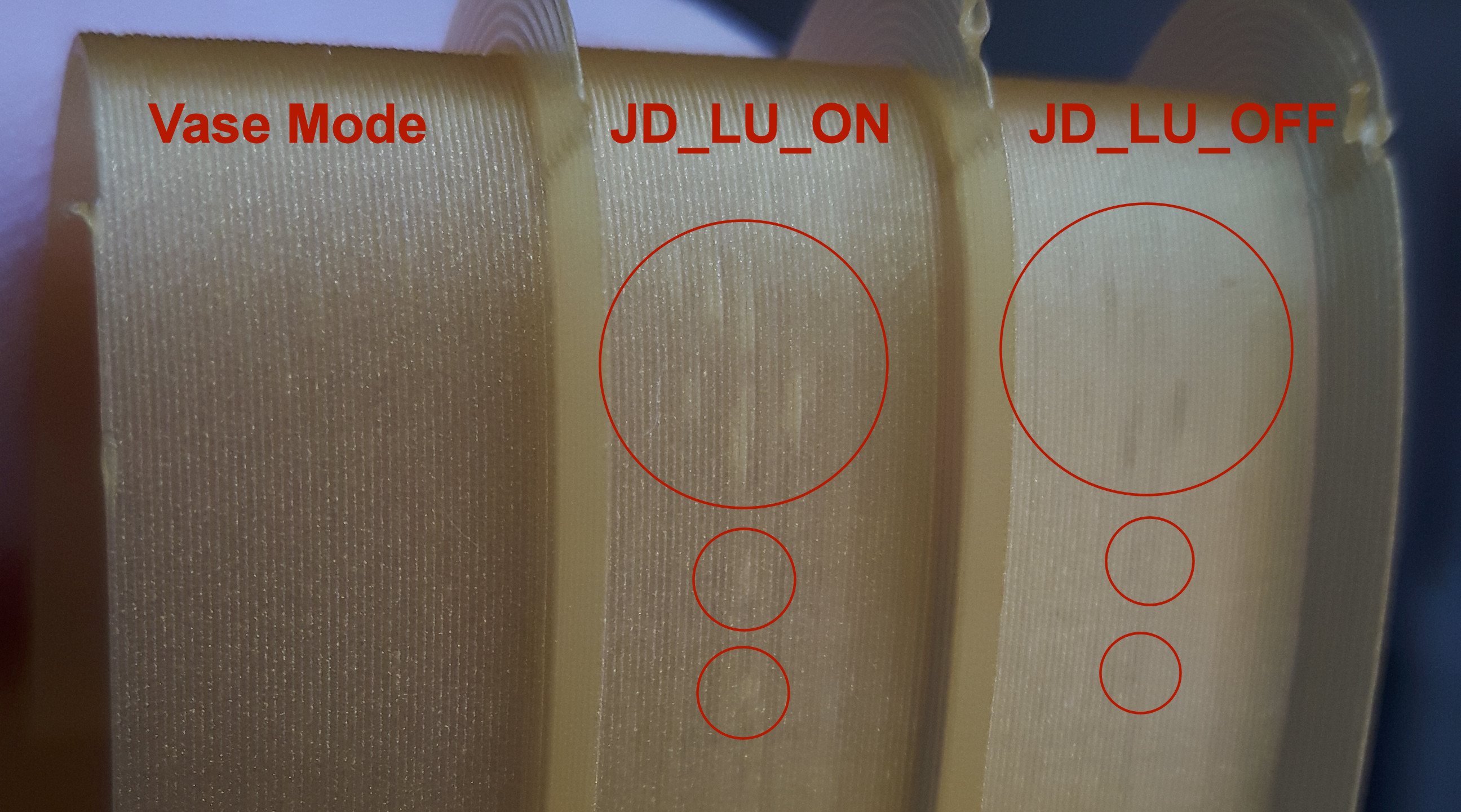
What does the picture tell me?
- We see bulges in both test prints which tells us that the different algorithms produce the exact same outcomes. I tried my best to take a picture where you hopefully can see it clearly. The bulges on both prints are present at the same spots.
- However when we compare the test print done in vase mode we find that there are no bulges at all. The print is completely clean.
My question is now why? Has it to do with the nozzle constantly moving in Z axis in vase mode?
In my opinion the walls should look the same, either in standard or vase mode.
Lord-Quake
on 3 Jun 2020
Sorry guys. I had no time over the weekend. I was solving some personal issue.
@Lord-Quake
Vase mode was with LUT enabled or disabled?
daleckystepan
on 3 Jun 2020
LUT was enabled
Lord-Quake
on 3 Jun 2020
My question is now why? Has it to do with the nozzle constantly moving in Z axis in vase mode?
In my opinion the walls should look the same, either in standard or vase mode.
We have identified and fixed multiple of causes for stutter. But there is fundamental problems with how vmax_junction_sqr is computed which are rooted in the fact that we are working with discretized curves. And there is definitely also a bug in some slicers (for Cura, see this one) which make those problems appear in Marlin. Technically, this whole stutter thing - at least now that other bugs are fixed - is at least 50% a slicer bug.
To make it short: I would bet my ass, that the vase mode GCode does have consistent segment lengths and _no_ tiny segments (<0.2 mm), while the two regular GCode files have either inconsistent segment lengths or the occasional tiny segment (or both). Could you check?
XDA-Bam
on 3 Jun 2020
I only use 2 slicers
- 95% of the time Cura_SteamEngine 15.01 which is very old and bare version, no bells and whistles.
- 5% of the time ideaMaker simply because it has the best vase mode quality. I'll be using it more and more though.
The latest tests where all done with ideaMaker. However best I do the same tests with Cura_SteamEngine 15.01. Will report tomorrow.
Lord-Quake
on 3 Jun 2020
Could you upload the two GCodes you printed? I'll check them for tiny segments.
XDA-Bam
on 3 Jun 2020
Sure thing. Here you go:
Cube_40mm_V3_Files.zip
Lord-Quake
on 3 Jun 2020
@daleckystepan No need to apologize. Real life is much much more important than working on this.
Lord-Quake
on 3 Jun 2020
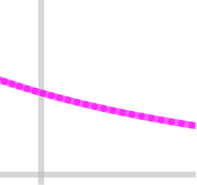
I have done segment length analysis with 0.01 resolution. Nothing special.
daleckystepan
on 3 Jun 2020
Maybe graph with 0.025 resolution will be better. Weird things around 0.
daleckystepan
on 3 Jun 2020
Well, there's definitely that inconsistency in the regular Cube_40mm_V3_Standard_1Wall.gcode. I can't analyze the vase mode one with this online tool, because there's too many layers. Regular looks like this:
Layer 10
Layer 38
On this curve, which I looked at, layers 0 to about 30 look good, then the segments start to shift around. That alone is not too problematic, but usually, the junction angle leading into those tiny segments isn't "correct" in the sense that it doesn't represent a circle of similar curvature. It would have to be significantly closer to 180° than on the longer segments. That is what reduces limit_sqr and forces slowdowns on these junctions. I still have to check if this is the case here.
XDA-Bam
on 3 Jun 2020
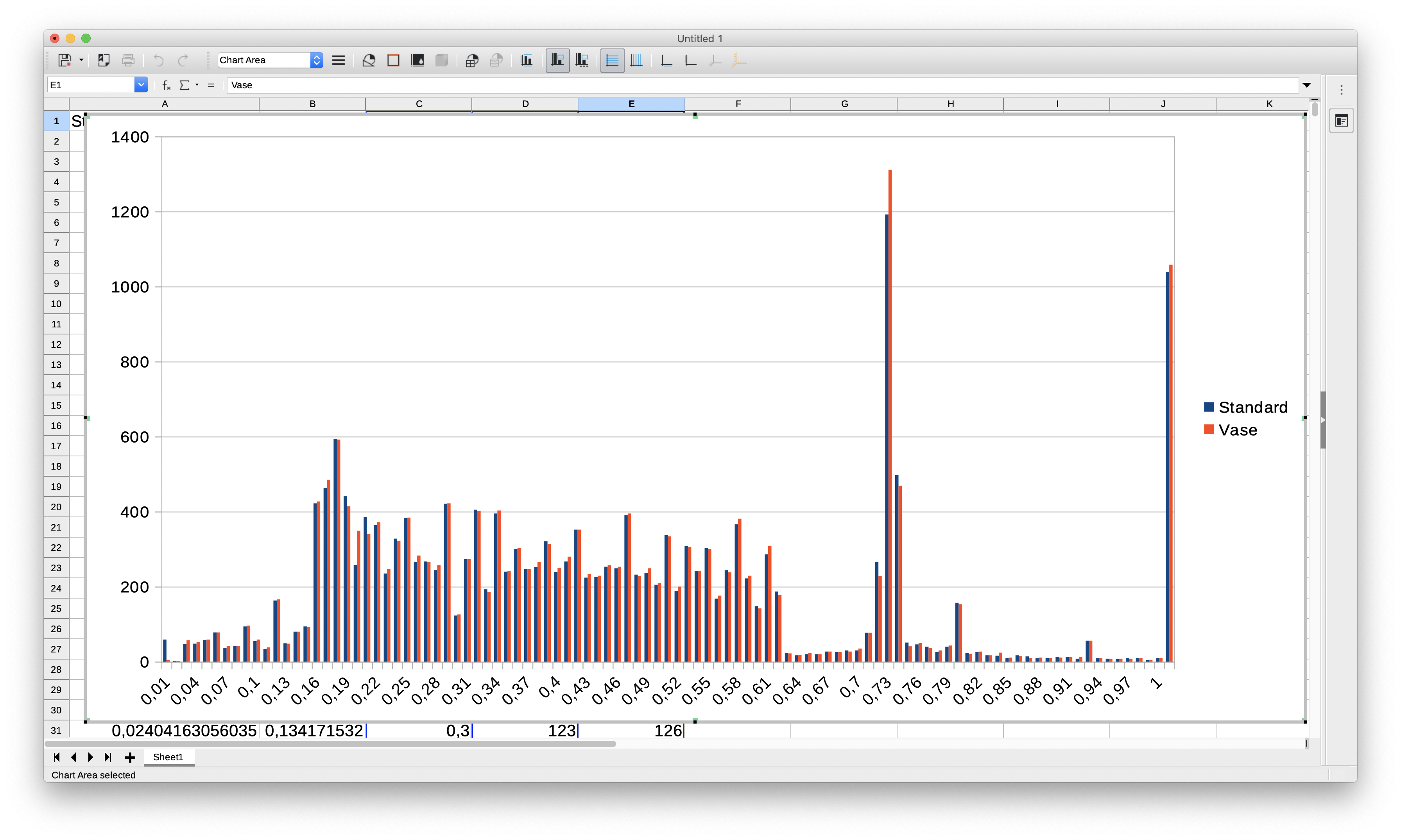
They're similar, but not the same. All following results computed using X, Y and Z moves. Extruder is ignored.
Overview
Cube_40mm_V3_Standard_1Wall.gcode:
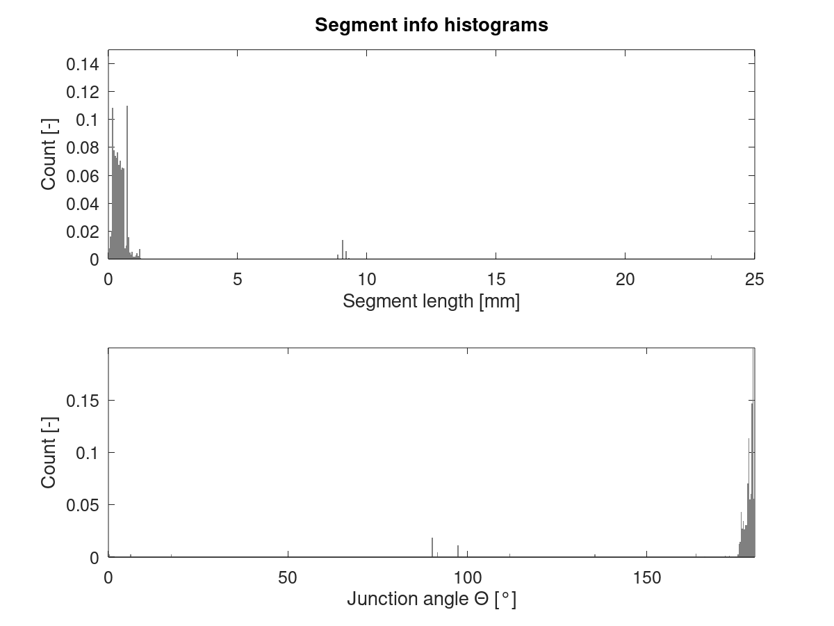
Cube_40mm_V3_Vase_Mode.gcode:
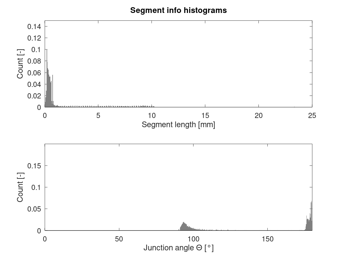
Detail
Cube_40mm_V3_Standard_1Wall.gcode:
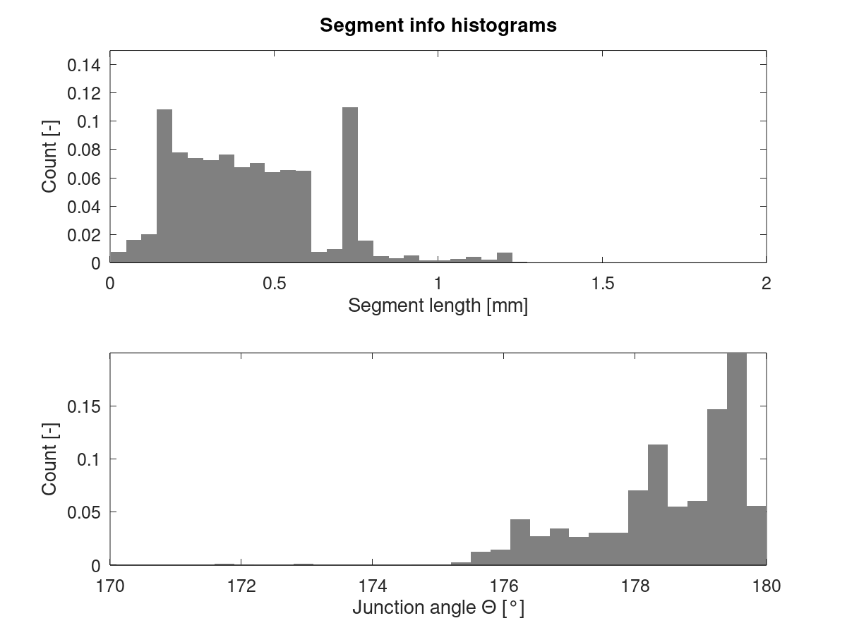
Cube_40mm_V3_Vase_Mode.gcode:
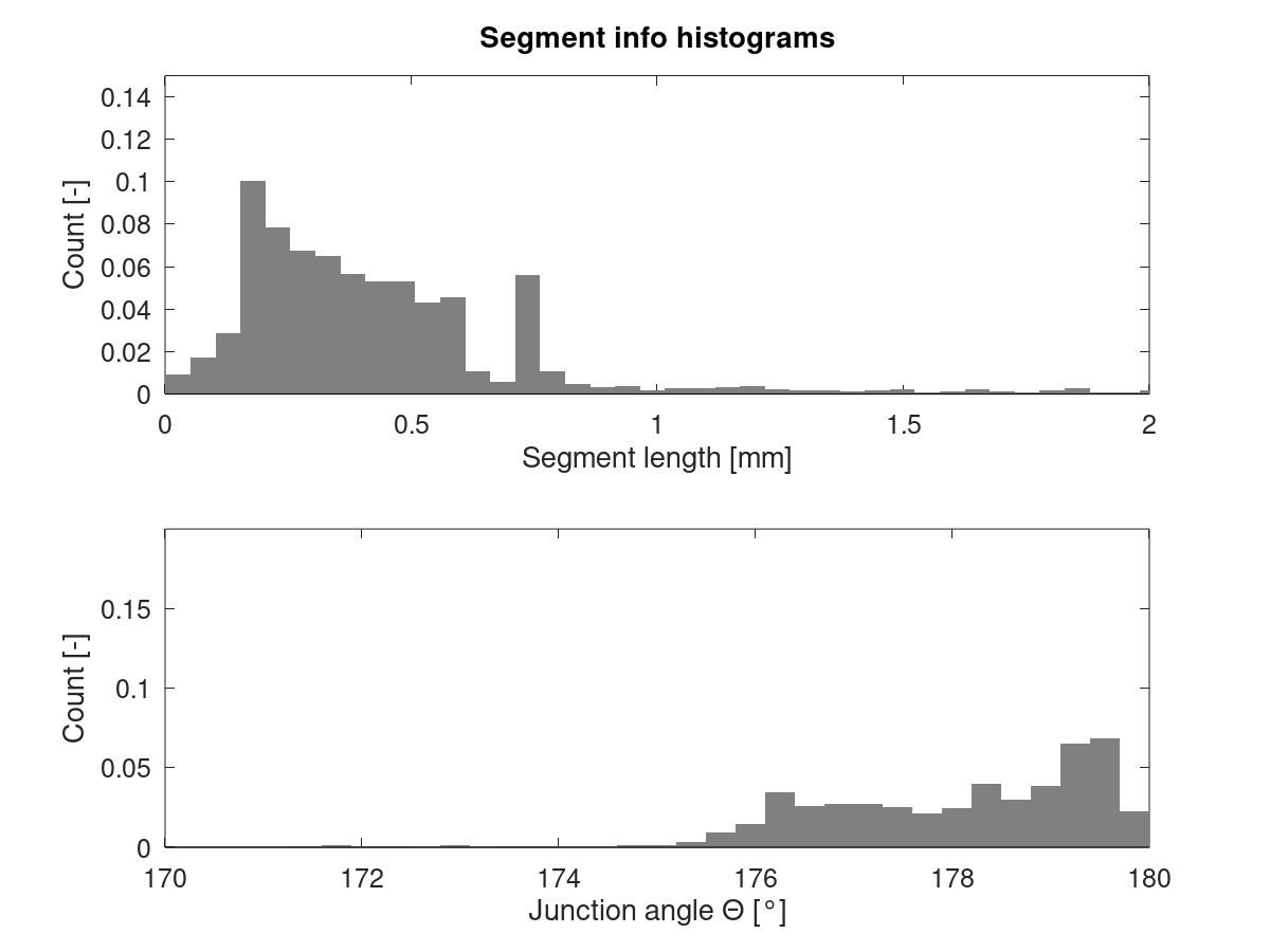
Standard mode has a peak in segment length around 0.7 mm which is less pronounced in vase mode. Also, there's a peak in junction angle around 179.5° which is mostly missing from vase mode.
EDIT: Updated histograms after fixing a bug which caused Z moves to be parsed incorrectly from the GCode. Only visibly affected vase mode data.
XDA-Bam
on 3 Jun 2020
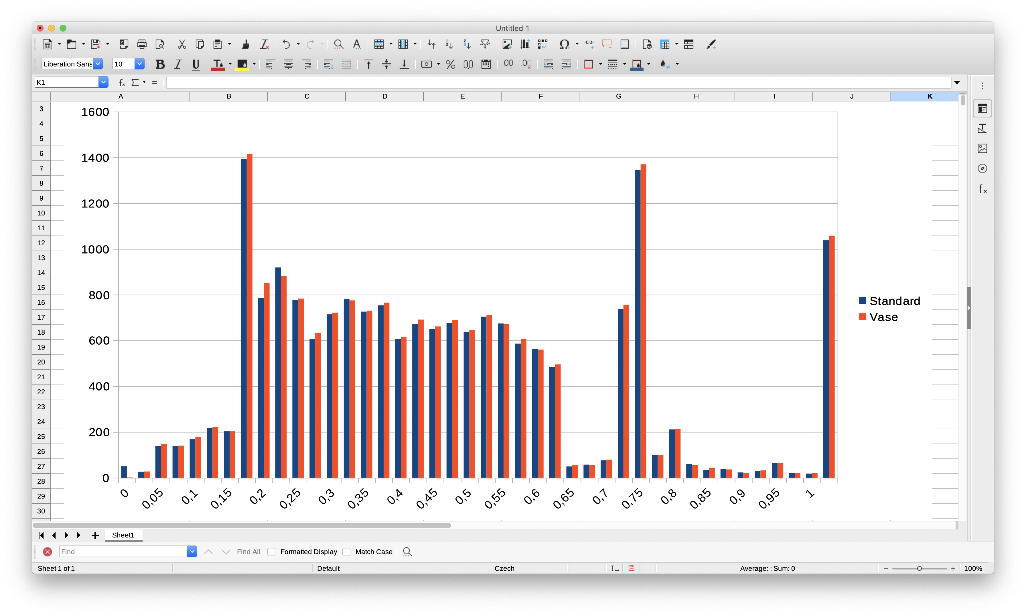
And here's the problematic part: If we calculate the equivalent radius of every segment + junction angle combination, both GCodes should be very similar - after all, they print the same part and thereby, the mean curvature is the same.
I define the equivalent radius as the radius of a full circle, constructed from copies of the current segment & the junction angle leading into it. This is what's used to calculate limit_sqr. For limit_sqr, the small angle sine approx is used. The precise formula is r_equiv = block->millimeters / sin(pi/2 - junction_angle/2). Results look like this:
Cube_40mm_V3_Standard_1Wall.gcode:
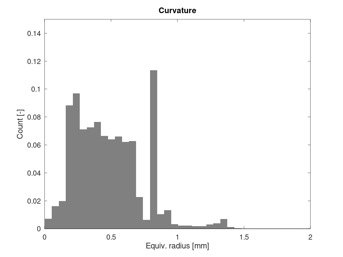
Cube_40mm_V3_Vase_Mode.gcode:
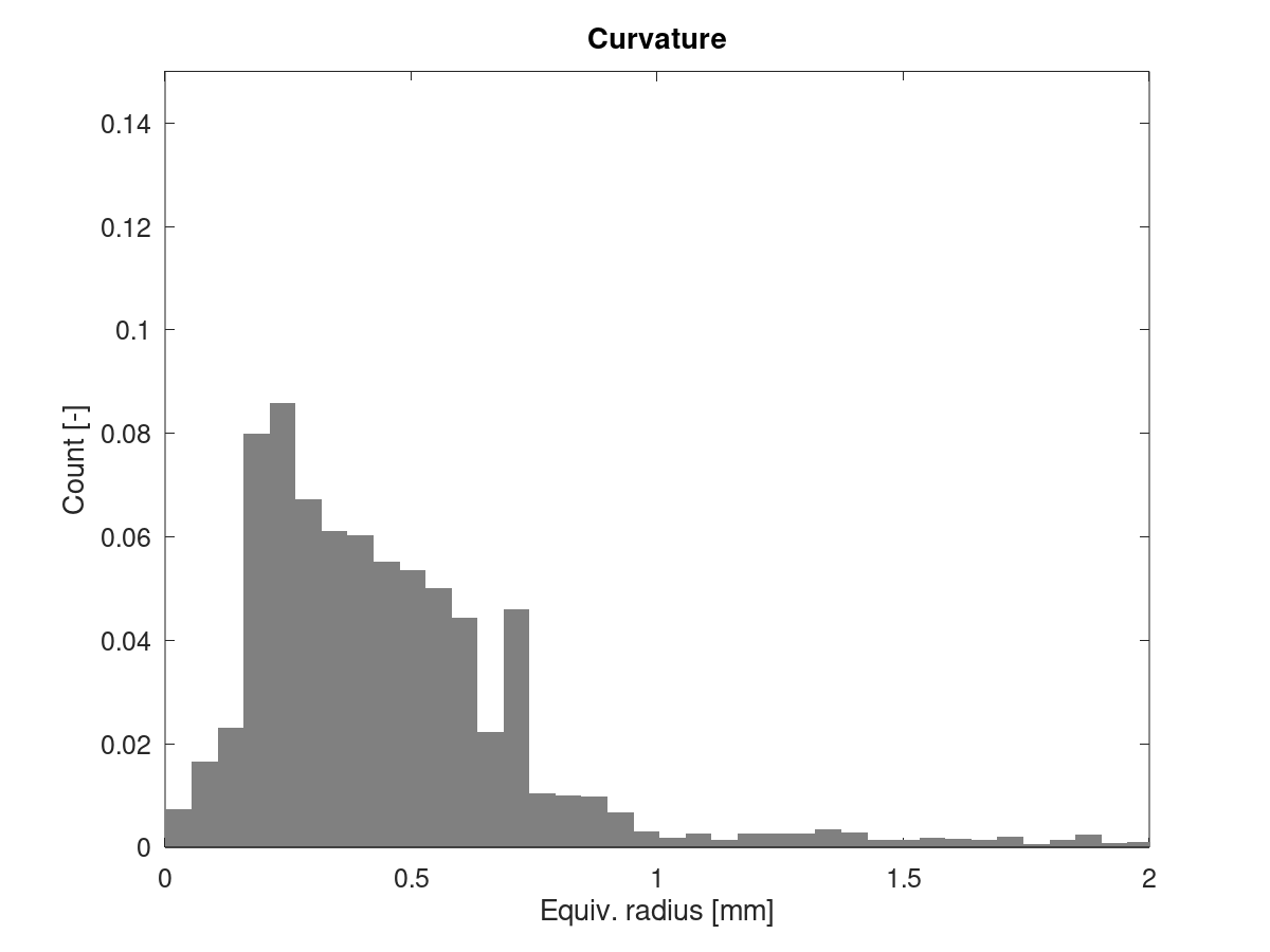
There's still that pronounced peak in the standard print, which is much smaller in vase mode. Vase mode looks a bit more nicely distributed, but no dramatic difference.
I still think that for the standard print, the slicer incorrectly distributes the junction angles between segments in those regions, where the alternating short/long segments appear. The histograms don't prove this, but we've seen that problem before on other parts which show stutter/drops in junction speeds.
EDIT: Update plots after fixing a bug in the GCode parser, which affected Z values. Mostly changed Vase mode, which now also has a small peak around 0.7 mm.
XDA-Bam
on 4 Jun 2020
Here are the results using Cura_SteamEngine 15.01 (Repetier-Host) in standard mode with the same settings as before.:

In these examples bulges are also evident (hard to see in the picture) at the same places with/out LUT albeit fewer.
I've also enclosed the g-code file I used for the above prints: Cube_40mm_V3_Standard_1Wall.zip
Lord-Quake
on 4 Jun 2020
The Cura sliced files looks quite a bit different concerning segment lengths.
Histogram detail:

Curvature / Equiv. radius:

Note that the max Y value is a bit higher than in the earlier plots. This GCode has much fewer segments below 0.5 mm. Segment length distribution isn't super consistent, but differences between consecutive segments are less pronounced than in the GCode sliced by ideaMaker. This is also evident from the sharper/thinner distribution in the histogram. A typical layer looks like this:

I'm still searching for a metric which is somewhat correlated with those bulges. I expected the width of the distribution of equivalent radii to be a candidate, but it doesn't look like it is 🤔
XDA-Bam
on 4 Jun 2020
@Lord-Quake Could you run the standard print sliced by ideaMaker again, but this time, comment out NOMORE(vmax_junction_sqr, limit_sqr); in planner.cpp? If you do this, it should be irrelevant if you use the LUT or not. But let's use it - just to be close to the defaults.
XDA-Bam
on 4 Jun 2020
Both instances? Lines 2505 and 2389
Lord-Quake
on 4 Jun 2020
There should be only a single instance of this exact line in the latest bugfix-2.0.x. This one:
https://github.com/MarlinFirmware/Marlin/blob/2d1cbf8e1d9f4d55f79b5c5d0628965472a7f92e/Marlin/src/module/planner.cpp#L2389
XDA-Bam
on 4 Jun 2020
Yes, you correct.... will do the test now.
Lord-Quake
on 4 Jun 2020
Well, this took a lot longer than I had wanted because my nozzle crashed in to the bed due to a little piece of filament stuck to the nozzle while leveling.....
After readjusting the printer and setting a new Z height I was able to print this.
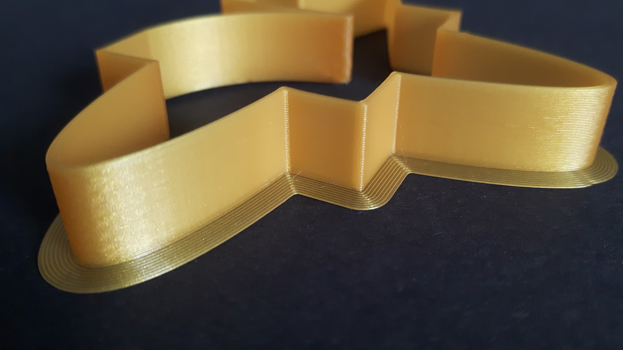
Check it out :-)

Just beautiful :-)
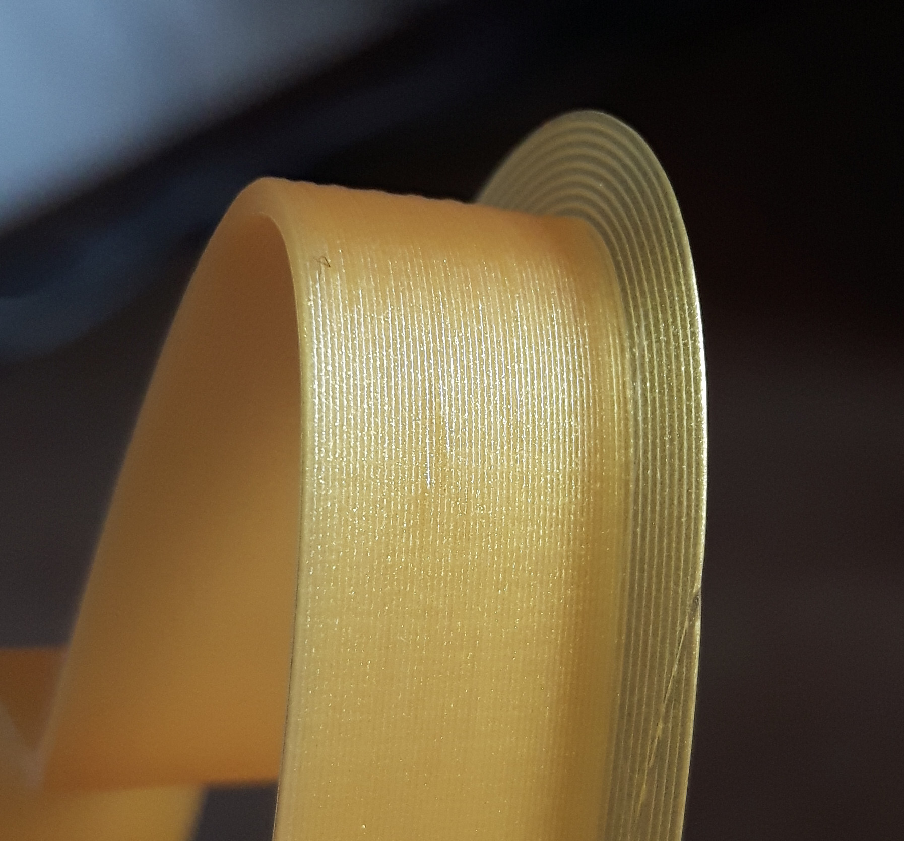
Take a look at the round curvature, how clean it now is. Compare this to the other prints where bugles are visible. The wall is also completely free of any bulges or line distortions.
In my opinion this is how Marlin should look like :-)
I will be doing more tests, not that this a fluke but I expect the other tests will show the same results.
Lord-Quake
on 4 Jun 2020
Even if it's a stupid question, but why do we need these limits: vmax_junction_sqr and limit_sqr?
What would happen if we don't have those limits?
qwewer0
on 4 Jun 2020
Just beautiful :-)
Take a look at the round curvature, how clean it now is. Compare this to the other prints where bugles are visible. The wall is also completely free of any bulges or line distortions.
Yeah, I agree. Also, that 100% confirms what I was suspecting:
- The problem is not the number of tiny segments itself
- A lack of CPU cycles is _not_ the main problem (not totally sure the LUT code wasn't optimized out by the compiler, though)
- The stutter & bulges are induced by
limit_sqrsetting excessively low junction speeds
As I said before, I also think that those excessively low junction speeds come from the fact, that the estimated radius is too low - most likely because some segments are aligned incorrectly by the slicer.
Thank you very much for testing this again! 🍻
XDA-Bam
on 4 Jun 2020
Even if it's a stupid question, but why do we need these limits: vmax_junction_sqr and limit_sqr?
What would happen if we don't have those limits?
The normal JD code determines junction speeds only based on junction angles. That means, if you slice an identical curve with a different number of elements, the one with more elements would print faster (because each junction angle is smaller, when there's more elements).
The additional code computing limit_sqr uses both, segment length and junction angle, to determine junction speeds. It basically assumes, that the current segment being planned is part of a bigger circle constructed of copies of this segment and then calculates that circles' radius. If everything were sliced perfectly and we had infinite steps per mm resolution, this approach would work fine. But it isn't and we don't 😄
XDA-Bam
on 4 Jun 2020
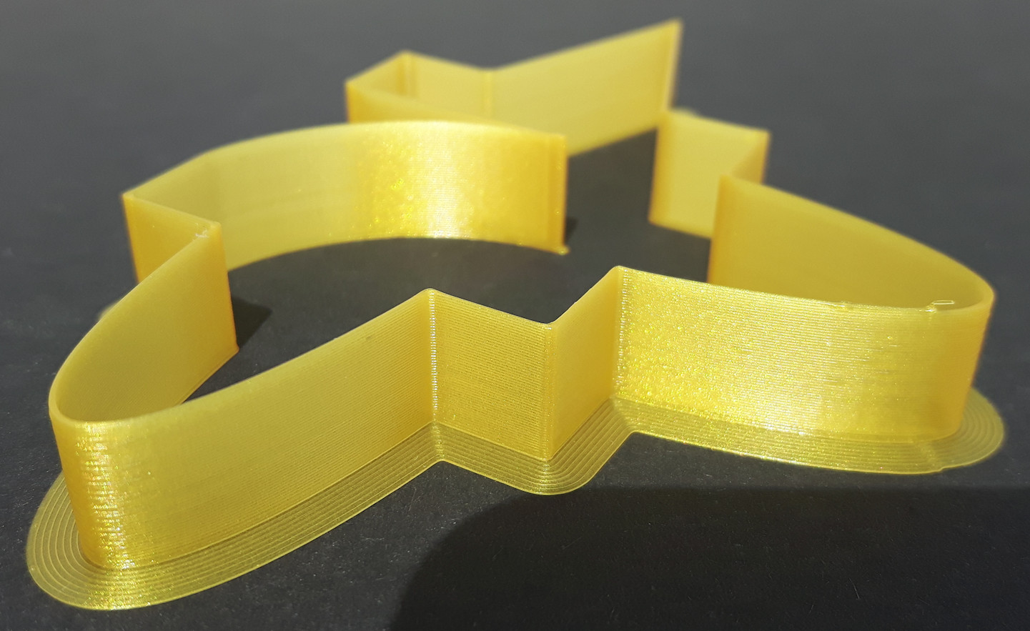
I did some more tests. Firstly I designed a new test object for quicker prints. I call it "Boomerang" :-)
Here the file if anyone wants to test: Boomerang.zip
One test was with 1 wall (0.4mm) and the other with 2 walls (2x0.4mm).

Pretty, aren't they.
Observe what happens when the fan gradually speeds up.....
Parts in full view:

Looking good right? Well, yes.....
However, I think I've found a "new" issue that probably is completely unrelated to our issue.
Look at the boomerangs.... I've been observing the issue ever since I started these tests.
Can you see it? :-)
Lord-Quake
on 4 Jun 2020
However, I think I've found a "new" issue that probably is completely unrelated to our issue.
Look at the boomerangs.... I've been observing the issue ever since I started these tests.
Can you see it? :-)
That line from 10 o'clock to 16 o'clock on the brim? 😀
XDA-Bam
on 4 Jun 2020
(buzzer) Incorrect ;-)
Lord-Quake
on 4 Jun 2020
Closeup (for the blind) Haha....

Lord-Quake
on 4 Jun 2020
Blob on topmost layer?
XDA-Bam
on 4 Jun 2020
(buzzer) We have a winner 👍
Seriously though.... On every print the nozzle halts for a split second on the last layer just before the print finishes. This is new....
Lord-Quake
on 4 Jun 2020
Weird. Maybe check your buffer size or turn off SLOWDOWN: If any change here influences the blob position, that narrows down the sources of potential bugs.
Back to the main topic: How do we proceed with our limit_sqr-problem? Simply removing the code will uncover the quirks of "pure" JD again. Other ideas?
XDA-Bam
on 4 Jun 2020
If that blob is about plannerbuffersize segments before the part is ready - try a M400 after the last moving g-code of the part. Could be EEPROM activity, closing files, updating printcounter, ... , things done when finishing a print. M400 will delay that until the part is finally printed - not only finally planed.
AnHardt
on 4 Jun 2020
@AnHardt M400 didn't help. This issue is new and I'll look into it deeper with a separate open issue entry if needed.
Lord-Quake
on 5 Jun 2020
From my point of view, we have definitely identified that limit_sqr is problematic. As there is no solution yet, I wanted to take the time to quickly visualize how I understand the problem is created (by the slicer, that is). Ultimately, the goal would be to brainstrom possible solutions.
Let's look at some random curve, which we slice into segments of different length. Our hypothetical slicer works well, but it's got some quirks. Now let's look at three of those sliced segments and their junction angles:
Slicing variant A

On slicing variant A you can see, that our hypothetical slicer decided to insert a small segment 2. And it distributed the junction angles Theta in a way that the angle 1->2 is close to 180° and the angle 2->3 is significantly below 180°. You could say that most of the curvature is attributed to the junction 2->3.
This is incorrect - the curvature should be distributed evenly amongst both junctions. But it is also not problematic for Marlin. The junction speed for segment 2 is computed using a low block->millimeters but divided by a very small junction_theta = (180° - Theta) << 1 and will be quite high. https://github.com/MarlinFirmware/Marlin/blob/75119c433af0a66236de07ef1c20548ea672104c/Marlin/src/module/planner.cpp#L2435
For segment 3, the junction speed will be a little bit lower than it should be for a perfectly sliced curve, but because the segment is much longer than 2, the junction speed will still be high enough to not be limiting in most real world scenarios. It is technically too low, but it will most of the time still come out at something like 60 mm/s, which happens to be enough to cause no problems during printing.
Slicing variant B

On slicing variant B you can see that our slicer again inserted a small segment, but this time, the junction angles are distributed in reverse: The angle on 1->2 is quite a bit lower than 180°, while the angle for the junction 2->3 is very close to 180°.
This is just as incorrect as slicing variant A. But this time, it also creates a big problem in Marlin: The junction speed for segment 2, which is very short and is divided by an angle junction_theta = (180° - Theta) >> 1, will be significantly lower than the ones before and after. It may be 40 mm/s if we are lucky, but often enough, it can be as low as 20 mm/s and less.
I am very, very certain that this is our main problem with limit_sqr. In short: If the slicer happens to accidentally combine a tiny segment with a junction angle to the preceeding segment which is larger than the "correct" one derived from local curvature, limit_sqr is simply crushed. Thereby, the printer is forced to slow down abruptly, causing stutter and surface imperfections.
Maybe it's the slicer's fault, maybe this comes from the polygon boundaries in the STL, I'm not sure. But I currently see no clean solution. What are your ideas?
XDA-Bam
on 10 Jun 2020
In each scenario you're looking at the eventual curvature / change in angle starting from point 1 and going out to point 3. In a longer scenario you could go out to point N. The total change in angle would seem to be the relevant issue.
What is interesting is that whenever you change angle in a set of 2 or more moves, the line directly from point 1 to your destination will "always" be shorter than the total of all the segment lengths. (That assumes a continuous curve and not a zigzag.) Of course, it's just the hypotenuse…. The shorter it is in relation to the total move length, the more acute the curvature.
So, anyway, given that we keep describing change in angle over multiple segments, it seems like we should be running some algorithm here that looks ahead from the start of the planner to the end of the planner, building on the current momentum, and which can account for all the angular change ahead, attenuating all the way back to the first planner segment.
thinkyhead
on 10 Jun 2020
…which is in a sense all that "jerk" does. It looks only at the amount of speed change being proposed on each axis by the "nominal speed" move that has been appended to the current buffer. Jerk limits are applied only on junctions where direction changes occur on one or more axes. The rest of the speed attenuation is handled in terms of acceleration and max feedrates per axis. Higher jerk values used to be the trick to get sharp corners.
So, it seems like what might work best is some combination of approaches. If there are weird edge cases that can mess with JD, clearly the long term solution is to have JD look for those cases and manage them by doing some form of averaging.
Perhaps there is some way to see these sudden jumps / drops in speed as they are about to occur and then apply extra logic to solve the dilemma….
thinkyhead
on 12 Jun 2020
I'm just a lurker so yell at me if I'm out of order, but I don't see a possible solution to this without reading ahead in the planner (or forcing gcode to use arc segments which obviously isn't a valid solution). So the first question (since I suck at reading C/C++) is how far ahead can we read? And is that a guaranteed amount (blocks I assume) or subject to variation based on other factors?
 campiosa
on 17 Jun 2020
campiosa
on 17 Jun 2020
@campiosa — We've had a good discussion on approaches to lookahead or "deviation accumulation" in another thread but I can't find the issue number at the moment….
thinkyhead
on 17 Jun 2020
Duplicate of #17342
thinkyhead
on 17 Jun 2020
Related issues
 ceturan
·
4Comments
ceturan
·
4Comments
 Anion-anion
·
3Comments
Anion-anion
·
3Comments
 Bobsta6
·
3Comments
Bobsta6
·
3Comments
 ShadowOfTheDamn
·
3Comments
ShadowOfTheDamn
·
3Comments
 otisczech
·
3Comments
otisczech
·
3Comments
Most helpful comment
Well, this took a lot longer than I had wanted because my nozzle crashed in to the bed due to a little piece of filament stuck to the nozzle while leveling.....

After readjusting the printer and setting a new Z height I was able to print this.
Check it out :-)
Just beautiful :-)
Take a look at the round curvature, how clean it now is. Compare this to the other prints where bugles are visible. The wall is also completely free of any bulges or line distortions.
In my opinion this is how Marlin should look like :-)
I will be doing more tests, not that this a fluke but I expect the other tests will show the same results.