Marlin: BIGTREETRECH SKR V1.1 32bit LPC1768 mcu
Good morning!another question/new board for marlin...
After a search on Google I cross upon this board that in my vision has identical footprint as a MKS GEN L board only new is that have an LPC 1768 mcu as a Sbase and Smoothieboard..
Can marlin run this board?
 weed2all
All 312 comments
Hmm looks like another variation on a smoothieboard. It is different from the MKS Sbase as it seems to be using the same SPI channel for the LCD and the LCD SD card (unlike the SBase which uses different channels and instead shares an SPI channel between the two SD card connectors). This same SPI channel is bought out on to the LCD/SPI/SD header and is likely to be used when talking to TMC SPI devices. This may cause problems with some LCD displays. I'm not sure if there is a good pins.h file for this configuration so it may need a new one.
 gloomyandy
on 12 Dec 2018
gloomyandy
on 12 Dec 2018
Yeah...but in my opinion this is better because of swapable drivers...i know that you can add external drivers to Sbase...but is not the same thing...
weed2all
on 12 Dec 2018
I wasn't saying if it was better or worse, just pointing out that it is different from what is probably the closest match in terms of existing pins files and some of the changes that will probably be needed if anyone wants to get one working.
gloomyandy
on 12 Dec 2018
I have one sitting here I plan on installing on a corexy. I just need to find time to get around to it. It should be simple to get up and running. If I get to it before someone else I will submit a pull request to add a new board type and a pins file.
 dot-bob
on 16 Dec 2018
dot-bob
on 16 Dec 2018
That will be awsome!
weed2all
on 16 Dec 2018
Also looking at this board (actually just ordered one). Having it supported, hopefully also with support for 12864 RepRap Full Graphics LCD and MksMini would be awesome ....
As far as I can see, some pins are not the same as on the Smoothieboard (source: [https://www.biqu.equipment/collections/control-board-kits/products/bigtreetech-skr-v1-1-motherboard-32-bit-smoothieboard-arm-cpu-control-board-open-source-for-tft3-5-printer-pannel])
 bipsendk
on 20 Dec 2018
bipsendk
on 20 Dec 2018
I just noticed, there are some minor issues regarding the picture with the pin assignments. Both EXP connectors are shown as EXP1 .... And 0.15 is apparently connected on both EXP1 and EXP2, and 0.16 only exists on the LCD/SD/SPI pin array (which I think is a bug in the picture)...
bipsendk
on 20 Dec 2018
Hello i orderd some one to.... I'm in contact with The Dealer and i ask him about the Problems .. i will Report You...
 XneddyX
on 20 Dec 2018
XneddyX
on 20 Dec 2018
I am not so familiar with the LCP1768 - but would it be possible to use e.g. the Y_MAX (P1_26) as (software) PWM output to control a BLtouch probe ?
bipsendk
on 21 Dec 2018
Seems like some work already is in progress: #12689
bipsendk
on 21 Dec 2018
other good board for marlin...?
REMRAM
https://youprintin3d.de/elektronik/open-source/1029/remram-v1.5-first-edition.html
 hectori4502
on 23 Dec 2018
hectori4502
on 23 Dec 2018
other good board for marlin...?
REMRAM
https://youprintin3d.de/elektronik/open-source/1029/remram-v1.5-first-edition.html
Also more than 4 times the cost of SKR, and not with replacable stepsticks.
According to the description, that board is already supported by Marlin 2.0:
"Zur Zeit nur Marlinunterstützung V2.0"
bipsendk
on 23 Dec 2018
This is the answere from BIQU BQ: "Hello friend.
The pin out photo is right.
You can see this video.
It can work with 12864LCD.
https://www.facebook.com/echo.li.520562/videos/226299174934140/?t=37"
XneddyX
on 24 Dec 2018
This is the answere from BIQU BQ: "Hello friend.
The pin out photo is right.
You can see this video.
It can work with 12864LCD.
Well, checking with the pinout of the RepRap Discount Full Graphics LCD, it would mean that the LCD4 pin on EXP1 is connected to the SCK pin of EXP2..
Also, they pinout shown designates EXP1 and EXP2 on the PCB - but the descriptive text states 2 connectors named EXP1 - so some sort of typo definitively exists on their pinout reference...
I will check up on it once I receive the board, that I have ordered...
bipsendk
on 25 Dec 2018
As I said above I think this board shares a single SPI bus between the LCD display and the SD card attached to the LCD so it is probably correct that LCD4 (EXP1) and SCK(EXP2) are connected to the same pin.
gloomyandy
on 25 Dec 2018
I am not so familiar with the LCP1768 - but would it be possible to use e.g. the Y_MAX (P1_26) as (software) PWM output to control a BLtouch probe ?
I ask to Aliexpress store about how to connect a BLtouch, this is the answer "they can not be connected to use, because SKR does not have the appropriate port."
If someone can connect a BLtouch then I would like to order it.
 Nuttavoot
on 25 Dec 2018
Nuttavoot
on 25 Dec 2018
According to the smoothieboard bltouch wiring you wire can wire the servo to 1.23, 2.4, 3.25 or 3.26
http://smoothieware.org/zprobe#bltouch-or-servo-retractable-touch-probe
on the SKR 3.25 and 3.26 are on the LCD/SD/SPI header so in theory it should work.
 b0ssman
on 27 Dec 2018
b0ssman
on 27 Dec 2018
a i didnt see that they are using 3.25 and 3.26 for the lcd as well.
but 1.26 is also hardware pwm capable.
http://smoothieware.org/pwm-capable
b0ssman
on 27 Dec 2018
i just ordered a SKR board. the price is unbeatable
b0ssman
on 27 Dec 2018
a i didnt see that they are using 3.25 and 3.26 for the lcd as well.
but 1.26 is also hardware pwm capable.
http://smoothieware.org/pwm-capable
That smoothie board in the above link uses LCP1769, will it be same as LCP1768 ?
Nuttavoot
on 28 Dec 2018
The LPC1769 is just a carefully selected version of the LPC1768 that can run at a faster clock speed. So yes the pins are the same.
gloomyandy
on 28 Dec 2018
i just ordered a SKR board. the price is unbeatable
Keep us posted for progress.
Nuttavoot
on 29 Dec 2018
Check out this branch from BIQU directly for the SKR:
https://github.com/Msq001/Marlin-bugfix-2.0-biqu
Source:
https://www.facebook.com/groups/505736576548648/permalink/604785386643766/
 talldonkey
on 2 Jan 2019
talldonkey
on 2 Jan 2019
Personally I prefer native support in the main branch - but as far as I can see from the commits, it is more or less already done. I am still waiting for my board, will test the bugfix-2.0 as soon as I can put it on the board (I have already tried to test-compile it in VScode without issues).
bipsendk
on 2 Jan 2019
I was able to get the latest Marlin 2.0 running on the SKR, but my REPRAP_DISCOUNT_SMART_CONTROLLER is not working. The backlight is coming on, but it's blank. It's not the contrast, so I'm wondering if the pins.h is correct for this combination. Did anyone manage to get the same combination to work?
 040medien
on 5 Jan 2019
040medien
on 5 Jan 2019
@040medien it is not the same board but this one is pretty similar to the Sbase in many respects, so you may want to check out this thread (if you have not done so already) https://github.com/MarlinFirmware/Marlin/issues/12796
gloomyandy
on 5 Jan 2019
Thanks for the pointer @gloomyandy - I made a mistake in my post - I'm actually trying to use the REPRAP_DISCOUNT_FULL_GRAPHIC_SMART_CONTROLLER, but no luck so far. According to the post you linked to, this should work.
Edit: Never mind, the display was broken. I tried it with an otherwise identical display and it worked.
040medien
on 5 Jan 2019
Hello 040 medien . I bought a skr v1.1 to and I have a reprap discount lcd from my Anet A6 but I can't made it work. The backlight isn't coming.
 Miroslav57
on 6 Jan 2019
Miroslav57
on 6 Jan 2019
Is that a standard RRD GLCD? If so, try flipping the cables 180 degrees. It's easiest if you carefully pull off the black plastic receptacles on either the board or the LCD.
040medien
on 6 Jan 2019
Standard I thinks .It is a model 12864 with the scroll button and the reset button on the right of the screen . I already have turn th cable in.every way possible
Miroslav57
on 6 Jan 2019
I just checked, it's not standard:
https://github.com/MarlinFirmware/Marlin/blob/bugfix-2.0.x/Marlin/src/config/examples/Anet/A6/Configuration.h
Use ANET_FULL_GRAPHICS_LCD instead.
040medien
on 6 Jan 2019
I used this display before
You need a custom cable or change the pins in the firmware, its not trivial.
You may consider buying a different display, the RRD GLCD is quite cheap
 kAdonis
on 6 Jan 2019
kAdonis
on 6 Jan 2019
Ok thanks a lot . I will buying a new screen . Maybe an mks tft35
Miroslav57
on 6 Jan 2019
Just know that these TFTs work compelely differently. Last I checked you couldn't even see the current printing status on them.
040medien
on 6 Jan 2019
Ok so I have purchase a rrd glcd . Another questions did you succeed to install the driver for windows ? My computer didn't recognize the board
Miroslav57
on 6 Jan 2019
Sorry, I'm using OS X.
040medien
on 6 Jan 2019
What version of Windows do you have? The driver is already there for Windows 10. For other versions you can find it here: https://github.com/MarlinFirmware/Marlin/tree/bugfix-2.0.x/Marlin/src/HAL/HAL_LPC1768/win_usb_driver
Others have reported that this driver works fine for them.
gloomyandy
on 6 Jan 2019
It is for windows seven
Miroslav57
on 6 Jan 2019
So did you try the driver I gave a link to? What happens?
gloomyandy
on 6 Jan 2019
No sorry tomorrow i will
Miroslav57
on 6 Jan 2019
I change the usb cable and now it work fine
Miroslav57
on 7 Jan 2019
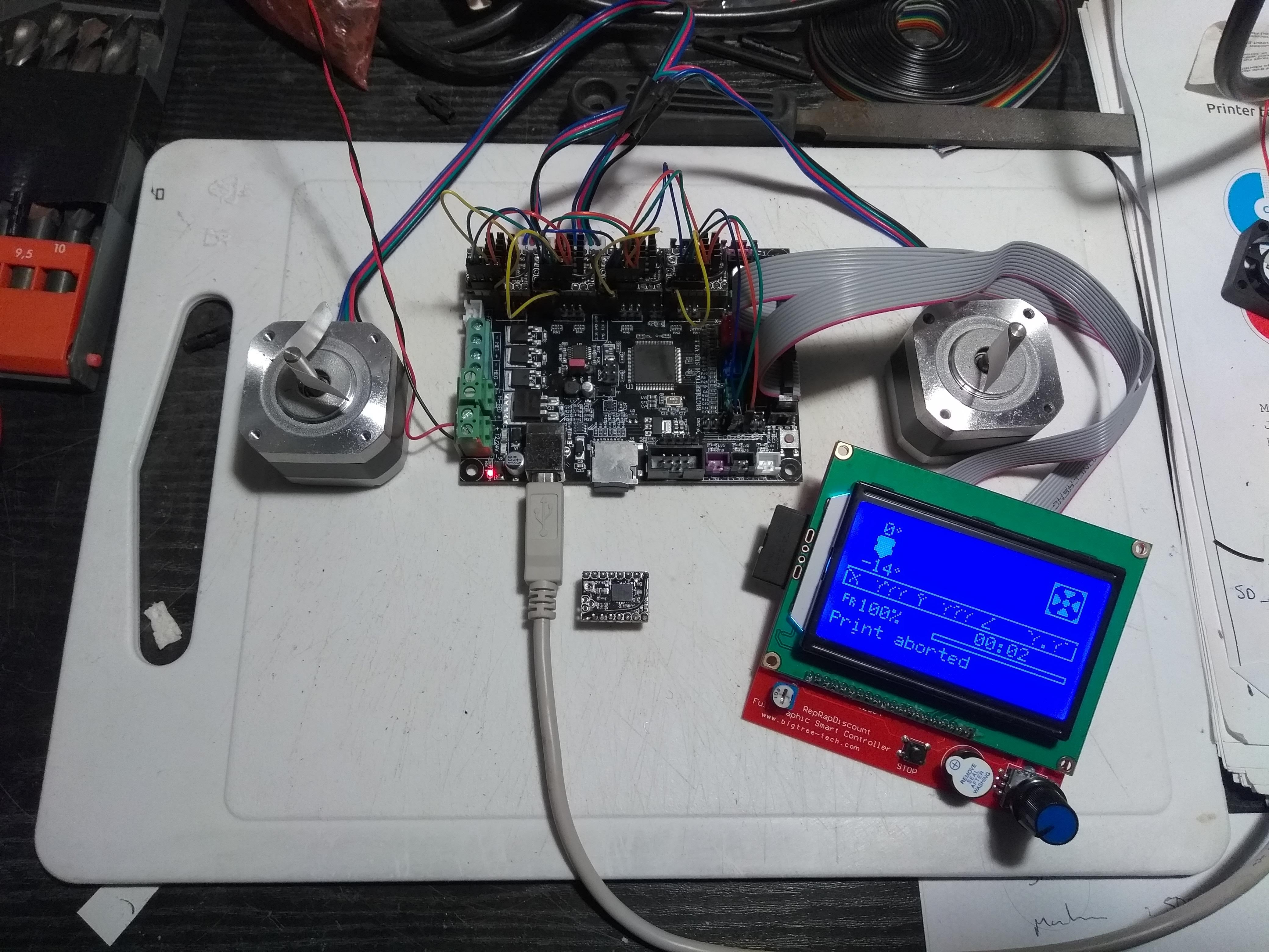
I have just received this board over the mail, and right after unboxing I realized what you were discussing here, that most of the pins are not broken out, they are just copies of aux1 and 2... Still, I am planning to hook it up with 3x tmc2130s and a bed leveling sensor, I will post some updates if I make any progress. If nothing helps, I might just hack some wires to the tiny pads of the microcontroller IC itself, as BIQU somehow failed to do so..
If I am mistaken, please correct me, I'd rather not hack into it unless I have to.
 myseg
on 8 Jan 2019
myseg
on 8 Jan 2019
If you look at bigtreetech's Facebook page, they posted a few videos running TMC2130 and Marlin 2.0 on it.
What's interesting is that they seem to have connected the drivers' CS pins to the enable pin next to each driver on the board. I've never seen that before, but it seems to work. Not sure which pins they use for SPI.
There are no servo pins for a bltouch, so I'll try to use ZMAX for that when I got some time.
040medien
on 8 Jan 2019
Yes, that is what I am concerned about, I have no idea how it could possibly work but ill give it a try today. If this works, the tmc2130 could work like that on other boards too, making less wire bulk altogether. I don't have too high hopes though.
Still, it was 16 bucks, it's worth it to buy just for experiments
myseg
on 8 Jan 2019
they seem to have connected the drivers' CS pins to the enable pin next to each driver on the board.
Probably the drivers are enabled through SPI, so the EN pins are no longer needed, its a feature @teemuatlut is working on
AFAIK it is currently only supported for TMC2660 in mainstream Marlin, but its on the list for all smart drivers https://github.com/MarlinFirmware/Marlin/pull/11998#issue-220185771
@myseg it could work with Bigtreetech's Marlin fork, But that is just a guess
kAdonis
on 8 Jan 2019
I checked and Bigtreetech's Marlin fork doesn't add more than pins_BIQU_SKR_V1.1.h - so it should work in mainline as well if it works at all.
040medien
on 8 Jan 2019
Right now I am trying to hook up an lcd controller first, with no luck. BIQU completely screwed up the pins on exp1, rotating the outermost 4 pins 180° and leaving the 6 midde ones. I hope I did not fry my lcd.
Here is the code I have modified, all the other lcd code has been deleted before this. The screen turns on but it's blank white, but the beeper and rotary works. No idea about the sd card yet. I had to modify the parallel cables a bit, here's a pic of them:
link
I am starting to approach a dead end about the lcd, what could be possibly missing?
Code:
#if ENABLED(MKS_MINI_12864)
  #define MISO_PIN            P0_18   // (50)  system defined J3-10 & AUX-3
  #define MOSI_PIN            P0_17   // (51)  system defined J3-10 & AUX-3
  #define SCK_PIN             P0_15
  #define BEEPER_PIN          P1_30
  #define BTN_EN1             P3_25   // (31) J3-2 & AUX-4
  #define BTN_EN2             P3_26   // (33) J3-4 & AUX-4
  #define BTN_ENC             P2_11
  #define SD_DETECT_PIN       P1_31   // (49) not 5V tolerant   J3-1 & AUX-3
  #define KILL_PIN            P1_22   // (41) J5-4 & AUX-4
    //#define LCD_PINS_RS         P0_16   // (16) J3-7 & AUX-4
  #define LCD_SDSS            P1_23   // (16) J3-7 & AUX-4

  #define DOGLCD_CS           P0_15   // (16)
  #define DOGLCD_A0           P0_16   // (59) J3-8 & AUX-2
  #define DOGLCD_SCK          SCK_PIN
  #define DOGLCD_MOSI         MOSI_PIN
  // GLCD features
  //#define LCD_CONTRAST   190
  // Uncomment screen orientation
  //#define LCD_SCREEN_ROT_90
  //#define LCD_SCREEN_ROT_180
  //#define LCD_SCREEN_ROT_270

#endif // MKS_MINI_12864
Also, here is the corrected pinout for it ( exp2 is upside down for better visualization)
link
myseg
on 8 Jan 2019
Alright, got the sd card working, that's someting I guess
myseg
on 8 Jan 2019
The LPC1768 hardware SPI pins are:
  #define MISO_PIN            P0_17
  #define MOSI_PIN            P0_18
  #define SCK_PIN             P0_15
your MISO and MOSI pin definitions are swapped
Are you sure you see the external SD card and not the internal?
kAdonis
on 8 Jan 2019
FYI: It is a common problem, that some manufacturers rotate the IDC 10 pin connectors for EXP1 and EXP2 180 degrees.... I have also seen it on a MKS Gen v1.4 board (and using a standard RRD GLCD)
bipsendk
on 8 Jan 2019
Thank you all, I think I have figured it all out now. The geniuses at BIQU put the SCK pin (P0_15) to the lcd CS pin too (can be seen on the pinout too) no wonder it didn't work, ant that was why the sd worked and the lcd did not (I figured out some time before my post that I mistakenly swapped the miso/mosi, the external SD definitely works). Now I need to hack that pin CS pin to the free P2.6 on the LCD/SD/SPI breakout. Will keep you posted tomorrow.
myseg
on 8 Jan 2019
@myseg are you sure about the CS pin? Looking at this pinout:
https://ae01.alicdn.com/kf/HTB1NZmHaiDxK1RjSsphq6zHrpXac.jpg
it looks to me like pin P0_15 (SCK) and P0_16 (CS) are in the same place as on the MKS Sbase board (other than the SBase has the connector rotated) and that pinout works fine (at least it does with the RRD GLCD). P0_15(SCK) needs to go to both the SD card and the LCD.
What display are you actually trying to get working? The Graphics ones seem to work fine with the Sbase and other similar smoothie style boards but folks seem to have problems getting the simpler character ones (RRD SC https://reprap.org/wiki/RepRapDiscount_Smart_Controller) working. Perhaps you are running into the same issues?
gloomyandy
on 8 Jan 2019
I checked and Bigtreetech's Marlin fork doesn't add more than pins_BIQU_SKR_V1.1.h - so it should work in mainline as well if it works at all.
its already merged
b0ssman
on 9 Jan 2019
hello I want to use the mks tft32, which I used in the mks gen l by plugging directly into aux-1, but on this board it does not work, it turns on but the commands do not work. someone could help me out please.
 isnave
on 9 Jan 2019
isnave
on 9 Jan 2019
The tft32 is not really a display like the other more standard devices. It is more like having a separate small computer that talks to Marlin via a serial port and sends gcode commands to do things. This means you need to define a serial port to allow the tft32 to talk via. How have you configured the serial ports in your configuration file?
gloomyandy
on 9 Jan 2019
define SERIAL_PORT -1
define SERIAL_PORT_2 0
isnave
on 9 Jan 2019
I know it is the plate is 115000 baud and tft 250000 I did not remember ... what sweats
isnave
on 9 Jan 2019
@myseg are you sure about the CS pin? Looking at this pinout:
https://ae01.alicdn.com/kf/HTB1NZmHaiDxK1RjSsphq6zHrpXac.jpg
it looks to me like pin P0_15 (SCK) and P0_16 (CS) are in the same place as on the MKS Sbase board (other than the SBase has the connector rotated) and that pinout works fine (at least it does with the RRD GLCD). P0_15(SCK) needs to go to both the SD card and the LCD.What display are you actually trying to get working? The Graphics ones seem to work fine with the Sbase and other similar smoothie style boards but folks seem to have problems getting the simpler character ones (RRD SC https://reprap.org/wiki/RepRapDiscount_Smart_Controller) working. Perhaps you are running into the same issues?
So apparently, people at BIQU had no idea how the exp breakouts works, and they mapped the lcd CS pin (doglcd_cs) to the hardware SCK pin (P0_15) mistakenly. To access both the lcd and sd card, it needs two separate cs pins (DOGLCD_CS for the lcd, and SDSS for the SD) to work. The one SCK pin is enough, it only provides the clock, for both simultaneously.
This is not the same as a smoothieboard, the exp1 is not only rotated, it is completely messed up. I had to splice up the cable and remap the DOGLCD_CS pin to P2_06, and it finally works! See attached image. Now I will try the tmc2130s, hope they won't fry themselves...
This SKR v1.1 board is clearly a still at prototype stage, and we are the test subjects. Probably the v1.2 model will have correct pin breakouts. I really don't recommend anyone to buy it right now, unless they would want to use the tft32 screen (which I also do not recommend, the simple 12864 is far more useful). Better wait for a new version.

If I manage to hook up the tmc-s, I will post an update.
myseg
on 9 Jan 2019
Hi myseg, a BIQU employee seems to be actively designing the SKR 1.2 board at this FB thread/post, and has even included screens of the board/traces - I suggest you can provide that feedback directly to BIQU through this channel to ensure the same mistake isn't made and is actually fixed in SKR 1.2 . https://www.facebook.com/groups/505736576548648/permalink/607735353015436/
talldonkey
on 10 Jan 2019
Wow! Did not see that yet. From the snaps he took from the board file, it looks like they broke out several more pins, and also managed to use the tmc2130 spi mode toggle jumpers, too, so no more wiring!
I guess we have the reason why this 1.1 board is so cheap, they were probably already working on the other ones
myseg
on 10 Jan 2019
Also, as the new board comes out in a short time, I think the thread can be closed. Everyone that had issues, thank you for beta testing for biqu for free (even we had to pay them), now buy the new, revamped board, it might not have issues...
(joke)
myseg
on 10 Jan 2019
@myseg are you sure about the CS pin? Looking at this pinout:
https://ae01.alicdn.com/kf/HTB1NZmHaiDxK1RjSsphq6zHrpXac.jpg
it looks to me like pin P0_15 (SCK) and P0_16 (CS) are in the same place as on the MKS Sbase board (other than the SBase has the connector rotated) and that pinout works fine (at least it does with the RRD GLCD). P0_15(SCK) needs to go to both the SD card and the LCD.
What display are you actually trying to get working? The Graphics ones seem to work fine with the Sbase and other similar smoothie style boards but folks seem to have problems getting the simpler character ones (RRD SC https://reprap.org/wiki/RepRapDiscount_Smart_Controller) working. Perhaps you are running into the same issues?So apparently, people at BIQU had no idea how the exp breakouts works, and they mapped the lcd CS pin (doglcd_cs) to the hardware SCK pin (P0_15) mistakenly. To access both the lcd and sd card, it needs two separate cs pins (DOGLCD_CS for the lcd, and SDSS for the SD) to work. The one SCK pin is enough, it only provides the clock, for both simultaneously.
This is not the same as a smoothieboard, the exp1 is not only rotated, it is completely messed up. I had to splice up the cable and remap the DOGLCD_CS pin to P2_06, and it finally works! See attached image. Now I will try the tmc2130s, hope they won't fry themselves...
This SKR v1.1 board is clearly a still at prototype stage, and we are the test subjects. Probably the v1.2 model will have correct pin breakouts. I really don't recommend anyone to buy it right now, unless they would want to use the tft32 screen (which I also do not recommend, the simple 12864 is far more useful). Better wait for a new version.
If I manage to hook up the tmc-s, I will post an update.
Does the cardreader work? Can you share the config and wiring?
 jmdearras
on 10 Jan 2019
jmdearras
on 10 Jan 2019
Card reader works, you only need to change the pins file other than the wiring.
It's easy, the pin numbers are on the back side of the board, and also shared here previously. I connected two pins on the exp1 head, just because one of them was not present on the LCD/SPI breakout.
You only need to copy and paste this section, replacing in the entire ultipanel/lcd whatever section.
Mind you, this will make it not compatible with any other lcds you enable in configuration.h
/**
 * Smart LCD adapter
 *
 * The Smart LCD adapter can be used for the two 10 pin LCD controllers such as
 * REPRAP_DISCOUNT_SMART_CONTROLLER.  It can't be used for controllers that use
 * DOGLCD_A0, DOGLCD_CS, LCD_PINS_D5, LCD_PINS_D6 or LCD_PINS_D7. A custom cable
 * is needed to pick up 5V for the EXP1 connection.
 *
 * SD card on the LCD uses the same SPI signals as the LCD. This results in garbage/lines
 * on the LCD display during accesses of the SD card. The menus/code has been arranged so
 * that the garbage/lines are erased immediately after the SD card accesses are completed.
 */

#if ENABLED(MKS_MINI_12864)

  #define BEEPER_PIN          P1_30
  #define BTN_EN1             P3_25   // (31) J3-2 & AUX-4
  #define BTN_EN2             P3_26   // (33) J3-4 & AUX-4
  #define BTN_ENC             P2_11
  #define SD_DETECT_PIN       P1_31

  #define DOGLCD_CS           P2_06   // (16)
  #define DOGLCD_A0           P0_16   // (59) J3-8 & AUX-2
  #define DOGLCD_SCK          SCK_PIN
  #define DOGLCD_MOSI         MOSI_PIN
  #define DOGLCD_MISO         MISO_PIN
  // GLCD features
  //#define LCD_CONTRAST   190
  // Uncomment screen orientation
  //#define LCD_SCREEN_ROT_90
  //#define LCD_SCREEN_ROT_180
  //#define LCD_SCREEN_ROT_270

#endif // MKS_MINI_12864
@myseg - so with the definition above - and some rewiring of the LCD cables - it is possible to get the MKS_MINI_12864 to work - including the SDcard reader ?
It would be nice with a detailed description of which pins to connect where ...
bipsendk
on 10 Jan 2019
well, you turn the board around, there are the pin numbers. And to which pin goes where, it is in the code I posted just now. I have linked a pinout picture of both the mks12864, and the motherboard in this thread.
myseg
on 10 Jan 2019
Also, I have managed to hook up the tmc2130s, by using the X-min P1_29, and Y-min P1_27, and the second serial pins (P0_02 and P0_03, on the AUX-1 header) as CS pins (for 4pcs tmc2130-s). Connecting them to the enable pins leaded to erratic detection, but this way it works well. Shame that now I cant use the esp8266 wifi or other UART expansions though.
The other spi cables were simply connected onto the LCD/SD/SPI header pins, they are labeled.
Hope I helped everyone, after all it is not such a bad motherboard, it just lacks a lot of pins.
myseg
on 11 Jan 2019
So tmc2130 with hardware spi is working, good to know. I think we can use E1's en, dir and step pins too, besides unused endstops pins. So you can free uart2 pins.
We have to make compromise somehow.
 fape
on 11 Jan 2019
fape
on 11 Jan 2019
Could you do a closeup of the wiring in the upper left corner? I can almost make out all the connections.
jmdearras
on 11 Jan 2019
Anyone could share his config.txt file for rrd glcd for smoothiware . The buzzer always ring when I switch on the board
Miroslav57
on 12 Jan 2019
Turns out, I was horribly wrong.
The board is working perfectly with tmc2130s hooked to the enable pins (I have seriously no idea why or how, and also I can disable the steppers with gcode and that works well too, and won't interfere with the spi signals, probably that is too high frequency to trigger the enable pins), so the deafult config is right, and with the code I posted above, the mini12864 screen is working as well.
What I went wrong with was I have been testing the drivers with usb power, and that produced completely erratic behavior, but once the jumper was set to external supply, there were no errors. Furthermore, I was unable to correctly set up the endstop pins, and my spi cabling had its MOSI and MISO pins swapped, which at USB power gave correct readings, but at 12V, it stopped working and vice versa (also, no idea why).
Now it works well, but I have only tested it by homing the printer.
If anyone is interested, I can share the config, adv, and pins file, but mind you, I am using a delta printer, the files will need editing.
If anyone here is using a ramps or any 8 bit board, I would be glad if they could try setting the CS pins equal to the EN pins just to see if it works there too.
myseg
on 12 Jan 2019
try setting the CS pins equal to the EN pins just to see if it works there too.
Theoretically this is possible. But you can't move and send/revive spi-data at the same time.
So, first configuring the drivers, then just and only printing should work.
But polling, for example the temperatures, error states, ... , will mess up the print.
 AnHardt
on 12 Jan 2019
AnHardt
on 12 Jan 2019
"But polling, for example the temperatures, error states, ... , will mess up the print."
Unless you have things set to use SPI to enable the drivers? Does Marlin support this?
gloomyandy
on 12 Jan 2019
Card reader works, you only need to change the pins file other than the wiring.
It's easy, the pin numbers are on the back side of the board, and also shared here previously. I connected two pins on the exp1 head, just because one of them was not present on the LCD/SPI breakout.You only need to copy and paste this section, replacing in the entire ultipanel/lcd whatever section.
Mind you, this will make it not compatible with any other lcds you enable in configuration.h/** * Smart LCD adapter * * The Smart LCD adapter can be used for the two 10 pin LCD controllers such as * REPRAP_DISCOUNT_SMART_CONTROLLER. It can't be used for controllers that use * DOGLCD_A0, DOGLCD_CS, LCD_PINS_D5, LCD_PINS_D6 or LCD_PINS_D7. A custom cable * is needed to pick up 5V for the EXP1 connection. * * SD card on the LCD uses the same SPI signals as the LCD. This results in garbage/lines * on the LCD display during accesses of the SD card. The menus/code has been arranged so * that the garbage/lines are erased immediately after the SD card accesses are completed. */ #if ENABLED(MKS_MINI_12864) #define BEEPER_PIN P1_30 #define BTN_EN1 P3_25 // (31) J3-2 & AUX-4 #define BTN_EN2 P3_26 // (33) J3-4 & AUX-4 #define BTN_ENC P2_11 #define SD_DETECT_PIN P1_31 #define DOGLCD_CS P2_06 // (16) #define DOGLCD_A0 P0_16 // (59) J3-8 & AUX-2 #define DOGLCD_SCK SCK_PIN #define DOGLCD_MOSI MOSI_PIN #define DOGLCD_MISO MISO_PIN // GLCD features //#define LCD_CONTRAST 190 // Uncomment screen orientation //#define LCD_SCREEN_ROT_90 //#define LCD_SCREEN_ROT_180 //#define LCD_SCREEN_ROT_270 #endif // MKS_MINI_12864
Hi!
This code should be added to " Marlin-bugfix-2.0.x\Marlin\nits\pinspins_BIQU_SKR_V1.1.h " instead of the "#if ENABLED(ULTRA_LCD)" section?
I include Marlin-bugfix-2.0.x\Marlin\configuration.h "item" #define MKS_MINI_12864" and the code is compiled regardless of whether the code in the file" Marlin-bugfix-2.0.x\Marlin\nits\pinspins_BIQU_SKR_V1.1.h".
I don't understand why I don't get an error when the code is not added to " Marlin-bugfix-2.0.x\Marlin\nits\pinspins_BIQU_SKR_V1.1.h "
Maybe I'm adding the wrong one?
Sorry about my English, it's bad. I use translator.
link to my files in question
https://drive.google.com/file/d/1Ymonxv99G3UxjB0JRiSlgC8T2obmoKsP/view?usp=sharing
https://drive.google.com/file/d/1G2TrRmRZgu4e6UkGIm0sZZgQT9rPH9oP/view?usp=sharing
 rustam-rezvanov
on 12 Jan 2019
rustam-rezvanov
on 12 Jan 2019
Someone can tell me how xonfigure smoothieware for bl touch
Miroslav57
on 12 Jan 2019
Alright, the sdcard was not working as I expected. After initial testing I was happy it detected and listed at M20, however when printing from SD card the screen freezes always exactly after starting the actual print gcode, after the heating, homing, moving to position, toolchange and initial retraction (done with gcode, not in fw), always at the same step. I tried other slicers, other sd cards, other gcodes, manually deleting some gcode lines, it always stops at ~20 lines into it.
When connected to a PC (repetier-host), it shows repetitive SD read errors, which explains the screen freezing, it's polling the SD card with no result.
I find it extremely strange, as the printer starts, detects, lists, and even starts to print a bit with the SD, but then freezes. Also, sometimes it has some sd init fail errors too, they are mostly after I reset the printer when it froze. A new reset eliminates any init fails, and it detects and inits it well after.
Printing through usb works well, but it has the expected slowdowns at difficult geometry, which I really wouldn't like to have.
Here is my pins.h:
pins_BIQU_SKR_V1.1.txt
I am completely lost now, all day I searched for any similar problem, but found none.
myseg
on 13 Jan 2019
what about the exporting of the internal sd card via usb as mass storage? does that work?
b0ssman
on 13 Jan 2019
someone has managed to configure the tmc2130 and that it works correctly or the tmc2208 as uart. yesterday all day I was trying but nothing
isnave
on 13 Jan 2019
The tmc2130s work well for me even with the default pins.h, the problem is with the sd card. I will try if a4988s also reproduce the sd problem.
myseg
on 13 Jan 2019
you have the biqu configuration because to me in spi gives me tmc error, could you put a picture of the connections ???? the jumpers from under the tmc, you have taken them off ... jurrr sorry is that I'm going crazy
isnave
on 13 Jan 2019
After testing, a4988s did NOT reproduce the SD problem, so the tmc-s are probably overloading the SPI bus. Will try moving the tmcs to sw SPI.
myseg
on 13 Jan 2019
you have the biqu configuration because to me in spi gives me tmc error, could you put a picture of the connections ???? the jumpers from under the tmc, you have taken them off ... jurrr sorry is that I'm going crazy
How I configured it was I hooked up the CS pins to the EN pins, and connected the SPI pins to the HW SPI pins (MISO (SDO): P0_17, MOSI (SDI): P0_18, SCK: P0_15) on the board's LCD/SD/SPI header. the pins are labeled literally on the back of the board. If it does not work, check your wires and firmware, something must be wrong. Also test them on external power, usb power will NOT work, as I have posted above.
myseg
on 13 Jan 2019
I am so dumb I was overlooking this... When enabling SW SPI on the drivers, I was mapping the sw pins on the same hw SPI pins, which produced great results for some people (youtube: https://m.youtube.com/watch?t=1s&v=TtYmx60rZh0 ) but they were mapping the lcd pins to some other ones. Well I did it the other way: The MOSI and MISO pins I swapped to P0_02 and P0_03, (so I had to disable serial2), but left the SCK pin as original, P0_15 as the endstop pins produced unstable results, so I could use only 2 free pins. This way, it works and prints flawlessly, no LCD artifacts whatsoever. If anyone requests it I can send a cabling picture from my motherboard, but I think I explained it thoroughly through my posts here.
Greetings to everyone, and happy printing!
myseg
on 13 Jan 2019
Hi! I understand that you managed to solve the problem with the screen and SD card? Upload a photo of the Board and the configuration file and pin. It's hard for me to understand some things in text form.
rustam-rezvanov
on 13 Jan 2019
A picture is worth a thousand words thanks
isnave
on 13 Jan 2019
A picture is worth a thousand words thanks
picture and *pins_BIQU_SKR_V1.1.h file ;)
fape
on 13 Jan 2019
Here's a to-be-verified SKR 1.1 TMC2130 & BLTouch wiring digram thanks to a user in this post in BIGTREETECH's Facebook group. I have an SKR arriving tomorrow, so I'll follow-up when I can get everything on the bench.

 thisiskeithb
on 13 Jan 2019
thisiskeithb
on 13 Jan 2019
Could anyone share his marlin 2.0 files please ?
Miroslav57
on 13 Jan 2019
Hello all. Does anyone made the board work with Full graphic smart LCD controller. It seems that with Marlin 2.0, the SD car under the screen doesn't work for my part. And in Pin.h I don't see an if(REPRAPFULL...).
 NANKEBAB
on 14 Jan 2019
NANKEBAB
on 14 Jan 2019
Alright, my config is here: link
The wiring is almost the same as thisiskeithb wrote, only the SDI and SDO is connected to the AUX1 port, and to clarify it even more, here's a pic, with the LCD wired in:

If this does not explain it well enough, then I seriously cannot help you.
myseg
on 14 Jan 2019
Is the connection shown for the yellow wire to the the LCD correct? You seem to have it connected to a pin that the label to the right shows as not connected. Should it perhaps be going to the DOGLCD_CS pin (one pin up)?
Also the EXP1 header for this mks mini 12864 board does not seem to match the pins used on the Reprap full graphics smart controller board, which some users here may be trying to use, so beware if that is the case. The schematic for the "standard" board is here: https://reprap.org/mediawiki/images/5/51/RRD_FULL_GRAPHIC_SMART_CONTROLER_SCHEMATIC.pdf
this seems to match the pins on the control board pretty well, so you may well be able to get it to work without needing a custom cable. If my board ever shows up I will let you know as I have the the Reprap board and will be using that.
gloomyandy
on 14 Jan 2019
So is it possible in any way to use TMC2208 in UART-Mode ?
 Xilius
on 14 Jan 2019
Xilius
on 14 Jan 2019
So is it possible in any way to use TMC2208 in UART-Mode ?
You should probably be following this thread...
https://github.com/MarlinFirmware/Marlin/issues/12854
the basic problems need to be sorted out first. Having said that it could well be tricky to get access to enough pins to get the UART stuff working. The revised board that has been mentioned by some might be a better option.
gloomyandy
on 14 Jan 2019
Alright, my config is here: link
The wiring is almost the same as thisiskeithb wrote, only the SDI and SDO is connected to the AUX1 port, and to clarify it even more, here's a pic, with the LCD wired in:
If this does not explain it well enough, then I seriously cannot help you.
Did you try tmc with hardware spi (do not to define TMC_USE_SW_SPI, and use P0_17, P0_18) and with lcd&sd too?
fape
on 15 Jan 2019
My bad, the yellow connects to doglcd_cs, as seen in the pins file.
I have literally posted here before that I have tried hardware, and software spi on the original pins, which made the sd printing stop.
The guy yt video link I posted before also had to remap their pins, but he remapped the LCD mosi/miso pins not the tmc-s. Either one works. It seems that the sck pin can be used for both.
myseg
on 15 Jan 2019
I had a chance to play with this board today, but haven't tried out the TMC2130 driver config yet.
I hooked up a BLTouch per this simplified diagram and was wondering what everyone's thoughts were on "standardizing" the BLTouch pins in pins_BIQU_SKR_V1.1.h to repurpose Z-MAX as SERVER0 if you define BLTOUCH in Configuration.h since there are no servo pins on this board:
```//
// Limit Switches
//
// SERVO0_PIN and Z_MAX_PIN configuration for BLTOUCH sensor.
// See https://i.imgur.com/WbGFPAY.jpg
//
define X_MIN_PIN P1_29
define X_MAX_PIN P1_28
define Y_MIN_PIN P1_27
define Y_MAX_PIN P1_26
define Z_MIN_PIN P1_25
define Z_MAX_PIN P1_24
#if ENABLED(BLTOUCH)
#define SERVO0_PIN P1_24 // Z-MAX
#else
```
Yay/Nay?
If this should go in another issue, I'd be happy to create it.
thisiskeithb
on 15 Jan 2019
I had a chance to play with this board today, but haven't tried out the TMC2130 driver config yet.
I hooked up a BLTouch per this simplified diagram and was wondering what everyone's thoughts were on "standardizing" the BLTouch pins in pins_BIQU_SKR_V1.1.h to repurpose Z-MAX as SERVER0 if you define
BLTOUCHinConfiguration.hsince there are no servo pins on this board:// Limit Switches // // SERVO0_PIN and Z_MAX_PIN configuration for BLTOUCH sensor. // See https://i.imgur.com/WbGFPAY.jpg // #define X_MIN_PIN P1_29 #define X_MAX_PIN P1_28 #define Y_MIN_PIN P1_27 #define Y_MAX_PIN P1_26 #define Z_MIN_PIN P1_25 #define Z_MAX_PIN P1_24 #if ENABLED(BLTOUCH) #define SERVO0_PIN P1_24 // Z-MAX #elseYay/Nay?
If this should go in another issue, I'd be happy to create it.
You'll need some more else statements I think:
````
if ENABLED(BLTOUCH)
#define SERVO0_PIN P1_24 // Z-MAX
#else
#define Z_MAX_PIN P1_24
````
Also you'll need some if else statements for delta printers, because those use MAX endstops for homing and have the MIN available. On my delta I use Z-min for a switch probe.
 petieken
on 15 Jan 2019
petieken
on 15 Jan 2019
Also you'll need some if else statements for delta printers
@petieken Are BLTouches common on deltas? the SERVO0_PIN would only be re-mapped to Z_MAX_PIN if BLTOUCH is enabled in Configuration.h. Unless you mean the other min/max pins?
thisiskeithb
on 15 Jan 2019
Another point of confusion is that all MKS products have EXP1 and 2 sockets reversed as compared to the rest of the world.
jmdearras
on 16 Jan 2019
Anyone suceeded with internal SD card reader? Mine shows No SD card in Marlin menu, even after SD init.
 fakcior
on 16 Jan 2019
fakcior
on 16 Jan 2019
I've just got that working. You need to comment out the following line in the pins file:
#define SDSS P1_23 // (53)
change to
//#define SDSS P1_23 // (53)
You should probably also change the following:
#define LCD_SDSS P0_16 // (16) J3-7 & AUX-4
to
#define LCD_SDSS P1_23 // (16) J3-7 & AUX-4
Many thanks! It's working now. I think it should be commited.
fakcior
on 17 Jan 2019
someone has gotten, to run the tmc2130 by spi???
isnave
on 17 Jan 2019
@fakcior thanks for confirming that it works. I want to check a few more things out on this board then I'll put together a PR.
gloomyandy
on 17 Jan 2019
my bltouch make something crazy . Every 10 second he deploy et then retract but just one seconds. I have plug it like previous message in z max and z min
Miroslav57
on 17 Jan 2019
I got my SKR board.
Its running with 3 TMC2208 (non uart for now) + 1 A4988 on my delta.
Spliced up a custom cable and got a 2004 LCD running(not enough pins for the sdcard)
Connected an ESP8266 with ESP3D to get a web interface on the board.
So far its running. If they create a new version with standard EXT1 and EXT2 that would be nice but not that critical for me.
The SDSS change is working. I can copy files to it via usb external storage.
Does anybody know what needs to be changed so that the card is mounted on boot in marlin?
b0ssman
on 18 Jan 2019
Actually the EXT1/EXT2 is reasonably standard it just isn't intended to be used with the 2004 style LCD. If you use a RepRapDiscount Full Graphic Smart Controller then it plugs in with standard cables and just works (I have one here in front of me), you can also have the SD card reader on the LCD working if you want that.
As to your SD card question, there are probably a number of options. The first would be to try the following:
Adding
  /* power on init. sd card */
  #if ENABLED(SDSUPPORT)
    if (!card.cardOK) card.initsd();
  #endif
to void setup() of Marlin.cpp
Alternately since you are using a web interface does that offer you the ability to run gcode when it connects to the printer? If so you can issue a M21 command from there.
gloomyandy
on 18 Jan 2019
If you use a RepRapDiscount Full Graphic Smart Controller then it plugs in with standard cables and just works (I have one here in front of me), you can also have the SD card reader on the LCD working if you want that.
Tried it, stays dark for me. Also tried a MKS MINI12864, same...
 brandstaetter
on 18 Jan 2019
brandstaetter
on 18 Jan 2019
Tried it, stays dark for me. Also tried a MKS MINI12864, same...
Did you rotate the connectors 180 degrees?
b0ssman
on 18 Jan 2019
Did you rotate the connectors 180 degrees?
Oh so that's still needed? @gloomyandy made it sound like it isn't 😁
brandstaetter
on 18 Jan 2019
it depends on who made your lcd. rule of thumb. no light -> Rotate 180
b0ssman
on 18 Jan 2019
The one I have you did not need to rotate the connectors. It is this one...
https://www.amazon.co.uk/gp/product/B01LO20XGS/ref=ppx_yo_dt_b_asin_title_o04__o00_s00
made by bigtree-tech. If you have an MKS MINI12864 then you will probably need to hack around with the cable, probably not worth it.
gloomyandy
on 18 Jan 2019
Okay, so now I have light and a beeeeeep when I turn it on but nothing appears on screen (tried 2 different screens, same behaviour)
brandstaetter
on 18 Jan 2019
What pins file are you using? What else do you have defined. Keep things very simple I just took the basic config file (the one that comes as standard with 2.0.x) and set the board type and the display type, plug things in and it worked first time. Don't make any of the modifications listed in this thread.
What screen do you actually have?
gloomyandy
on 18 Jan 2019
I connected my SPI cables to the hw_spi pins, maybe these interfere.
I use the pins_BIQU_SKR_V1.1.h file with some minor modifications from this thread (defining the X_ENABLE_PINs and deactivating SDSS and changing LCD_SDSS to P1_23
the screen is a "Geeetech LCD12864 Square Reprap Smart Controller"
brandstaetter
on 18 Jan 2019
Are you sure you have the cables connected to the correct headers? You should probably try all combinations or cables and cable rotations, just to be sure.
There is a good chance that sharing the SPI pins with the display will cause a problem both for the display and for the steppers, especially if you are using the enable pins as chip select pins for the steppers. But I would not expect that to cause the sounder to beep. That is more likely to be a wiring problem.
The X_ENABLE pins are already there. Do you mean the chip select pins?
I'm not sure if that display has the same pins as that used by the original (it seems to have some "extra features"), but who knows!
gloomyandy
on 18 Jan 2019
Hey guys my bltouch work fine yet ! I just habe define the servo0 to 2.6 pin and now it works great
Miroslav57
on 19 Jan 2019
Okay, I tried all possible combinations, and guess what, you were right, @gloomyandy 😄 I now have a display on my screen. And it says TMC CONNECTION ERROR so I guess the shared pins are to blame.
Can I just remap them?
brandstaetter
on 19 Jan 2019
How do you have things configured for the TMC drivers? Are you using software SPI (you probably should), are you using a shared enable and CS line? What pins do you have configured for SPI to the drivers?
gloomyandy
on 19 Jan 2019
Oh and how do you have the SD card settings configured? Basically I really need to see your pins file.
gloomyandy
on 19 Jan 2019
The connection descriped in
https://github.com/MarlinFirmware/Marlin/issues/12632#issuecomment-454278292
may cause some problem due to logic level for 5V supply at the BLTouch. At 5V supply the BLTouch needs 5V logic levels. The 3.3V logic level caused problems with my BLTouch. After adding an level shifter betwwen the servo pin from the LPC and BLTouch it works without problem. Depending on the version of BLTouch there is an solder bridge on the BLtouch to switch between 5Vand 3.3V logic.
https://www.antclabs.com/bltouch
 Albundy1
on 20 Jan 2019
Albundy1
on 20 Jan 2019
So I have finally got my test system up and running. I have a RepRapDiscount Full Graphic Smart Controller with working SD card reader, 4 TMC2130 drivers with full SPI control and monitoring. All seems to be working pretty well. I decided that I did not really want to go the shared Enable/Chip Select route as it seems to me that this will not allow the use of SPI commands during printing. I assume this means that features like temperature monitoring etc. will not be available. So instead I have made use of a very recent faeture in Marlin that allows SPI control of the driver enable. This allowed me to free up the enable pins to use them as chip select. My configuration also shares the SPI pins with the display and SD card reader which means no extra pins are in use. I have a video clip of my test setup running here:
https://youtu.be/6Lc2UTLTB-I
You can see the setup here:
A more detailed view of the board:
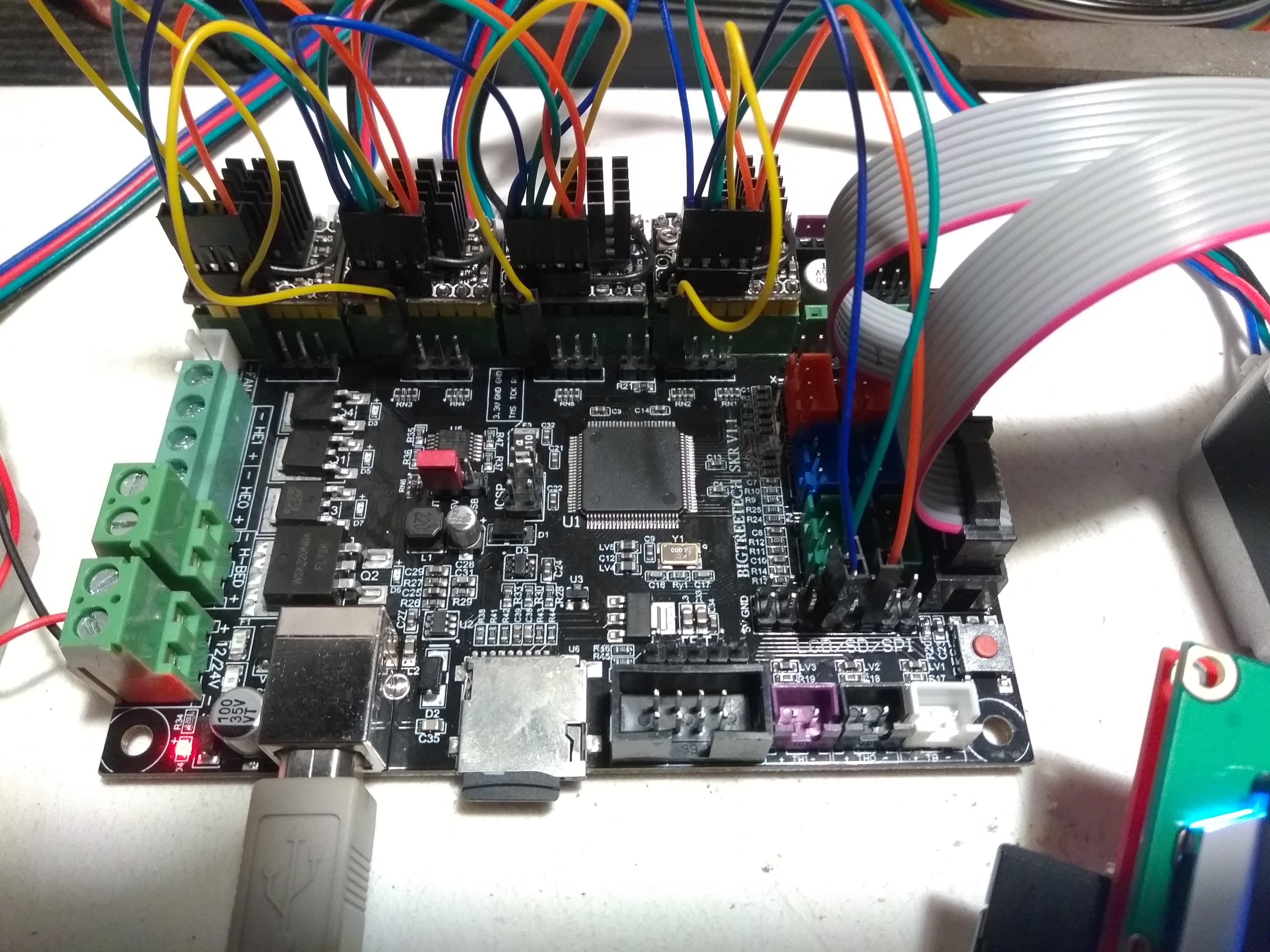
This configuration requires that the driver modules are modified. The Pin used for the enable signal needs to be removed (so it does not connect to the board), and this connection needs to be tied to GND. You can see my mods here:
The only real downside with this setup is that sharing the SPI bus with the display means that you get glitches on the display when either the SD card is active or Marlin is talking to the drivers. There are a few ways to work around this problem...
- Use a custom cable and break out the display clock line to another pin on the board (for instance P2_06).
- Use a different pin(like P2_06) for the TMC clock line, this reduces the screen glitches to just those from SD card access (which may not be a problem for you).
- Use 2 to remove the TMC glitches and also don't use the LCD mounted SD card reader. Instead either use USB printing, or use the SD card that is on the board (this would be my choice as this card can also be shared with a PC via USB).
My (minimal) configuration files are here:
https://github.com/gloomyandy/Marlin/tree/myskr/Marlin
The updated pins file I have used is here:
https://github.com/gloomyandy/Marlin/blob/myskr/Marlin/src/pins/pins_BIQU_SKR_V1.1.h
I will continue to test this config, and if all looks good will probably create a PR for this updated pins file.
gloomyandy
on 20 Jan 2019
@gloomyandy - if not using TCM2130 drivers - do you assume, that some of the available pins (not used for the RepRapDiscount Full Graphic Smart Controller and SD) could be used for a BLtouch ?
bipsendk
on 20 Jan 2019
I've no experience of using the BLTouch (I've always used an inductive sensor). But there are very few spare pins with this board. Once you have a display like yours there are only really 3 pins (TFT RX/TX plus P2_06) plus any unused endstop and temp sensor pins available. Oh and I suppose if you are not using all 5 steppers you will have four pins from that. The problem is that both the endstops pins and the temp sensor pins also have additional components attached to them, so they may or may not work when used for other purposes.
gloomyandy
on 20 Jan 2019
The connection descriped in
https://github.com/MarlinFirmware/Marlin/issues/12632#issuecomment-454278292
may cause some problem due to logic level for 5V supply at the BLTouch. At 5V supply the BLTouch needs 5V logic levels. The 3.3V logic level caused problems with my BLTouch. After adding an level shifter betwwen the servo pin from the LPC and BLTouch it works without problem. Depending on the version of BLTouch there is an solder bridge on the BLtouch to switch between 5Vand 3.3V logic.
https://www.antclabs.com/bltouch
Can you show me the level shifter that you use ? My BLTouch is a cloned and does not have that 3V selection.
Nuttavoot
on 21 Jan 2019
How do you have things configured for the TMC drivers? Are you using software SPI (you probably should), are you using a shared enable and CS line? What pins do you have configured for SPI to the drivers?
Oh and how do you have the SD card settings configured? Basically I really need to see your pins file.
I just enabled SW SPI but have yet to decide and connect
//#define TMC_SW_MOSI -1
//#define TMC_SW_MISO -1
//#define TMC_SW_SCK -1
brandstaetter
on 21 Jan 2019
I can confirm that SW SPI works but has anyone has any luck using _hardware_ SPI? I've wired the drivers into 0.15, 0.17 and 0.18 using these links https://os.mbed.com/users/Lerche/notebook/lpc1768-pin-functions/ https://os.mbed.com/users/Lerche/notebook/lpc1768-pin-functions/ as reference but all I get is FF:FF:FF:FF Bad response!
These exact same pins work with SW SPI but this bugs me. Anyone had any luck?
 khrazik
on 24 Jan 2019
khrazik
on 24 Jan 2019
@brandstaetter You will not be able to use the TMC monitor drive status if you use shared chip select and enable pins. The problem is that the monitor code needs to talk to the drivers during printing which means that more then one motor will be enabled. But that would also mean more than one CS will be set and you can't do that with SPI.
gloomyandy
on 24 Jan 2019
@khrazik Do you have any other SPI devices defined, like an LCD or SD card reader? They will be using the same SPI lines, which may well be causing problems (especially if they are using software SPI). Also do you have a display or anything esle plugged into the board (even if you do not have it defined in your config). We need to see your config and pin files really and details of your hardware.
gloomyandy
on 24 Jan 2019
@gloomyandy Sure. Note that the hardware configuration below WORKS with SPI in klipper, which I believe is hardware only. The driver reports, responds and is controllable using that firmware with that specific wiring arrangement. Therefore I'm assuming user error...
Here are my configs: configs.zip
I am using a modified standard SKR 1.1 pins file and vanilla config. The board is running bare. The configuration is powered by a laptop power supply (19V/4.5A) for testing purposes, with no SD card readers (save for the onboard one) nor LCDs installed, with a single stepper and motor attached to their respective Y axis ports. The steppers I have are BIQU V1.1 TMC2130, all of which are tested and confirmed to be working and properly configured for SPI (using Marlin in SW SPI mode). I am using the cable with shared MOSI/MISO/SCL signals and separate CS breakouts, which was supplied with the drivers. CS pins are connected to a Z+ endstop pin and E1 pins (4 pins total).
As mentioned, the steppers wake up in SW SPI mode and work beautifully, but if I comment SW SPI out, I can't get anything out of them. :/
khrazik
on 24 Jan 2019
@khrazik OK I think I see why it is not working for you. You have the SD card stuff setup so that Marlin will use the onboard SD card (this will also be shared with your PC via USB). This card reader is on SSP1 (the second hardware SPI device), which uses pins P0_07, P0_08, P0_09. The pins you are trying to use are P0_15, P0_17, P0_18 which are on SSP0 (the first hardware SPI device). Unfortunately Marlin currently only has support for a single instance of a hardware SPI device (which uses whatever MOSI_PIN, MISO_PIN and SCK_PIN are defined to be) and the TMC library uses the Marlin supplied device for the hardware SPI. So if you specify hardware SPI with your current configuration you will be talking to the wrong SPI bus.
You could fix it by configuring things so that Marlin uses an external card reader (and hence will use SSP0), which should then mean you will be using the correct pins if you specify that the TMC lib should use hardware SPI. But then Marlin will not have access to the onboard SD card. This may or may not be a problem for you.
Note that if you ever install an LCD display then this will also be sharing the SPI bus with the TMC drivers (and possibly the SD card reader as well) and for reasons I don't really understand the LCD code does not seem to like using hardware SPI if it is shared with other devices.
Hope the above makes sense.
gloomyandy
on 24 Jan 2019
It does.
for reasons I don't really understand the LCD code does not seem to like using hardware SPI if it is shared with other devices.
It's not the LCD-codes fault. It's a hardware problem with the ST7920s CE-line.
The latest ST7920 datasheet page 26 second paragraph, tells us, CE is broken, don't use it with together with other devices on the same bus.
The datasheet describes a, compared to other SPI devices, very different (broken) behavior of the controllers CE pin. In former versions of the datasheet a normal behavior was described. (Errata)
Mostly only a garbed display is observed. Mostly a rewrite of the display right after a sd-operation (or other SPI-operation) makes the problem nearly invisible.
Safest is to ether use a separate spi-bus for the ST7920 or use some logic-gates to keep SCLK and SI quite when CE is not selected.
AnHardt
on 24 Jan 2019
@AnHardt Thanks, yes I was aware of the CE issues, but I don't think that is what stops you from using hardware SPI as opposed to software SPI when sharing the bus. I have a feeling it may be that the two devices may be using different clock speeds and that perhaps the LCD hardware SPI code does not reset the hardware clock speed before each new request, but I'm really not sure.
gloomyandy
on 25 Jan 2019
@gloomyandy Thank you for the explanation, this makes sense. I would like to clarify one thing for future reference - you've written that Marlin supports only a single hardware SPI bus, and I understand that the onboard card reader is connected to SSP1, but it seems that LCD headers are connected to SSP0. And there are reports that the LCDs work correctly in tandem with the SD card reader. How is that possible?
khrazik
on 25 Jan 2019
It's not directly Marlin, it's Arduino SPI library API what is not able to handle more than one hardware SPI-buss - limiting Marlin.
AnHardt
on 25 Jan 2019
Sorry I was not clear on that, it is all a little complicated!
The current Marlin HAL interface provides an SPI interface that can be implemented by either software or hardware that is used by Marlin for SD card access. This same interface is also used by the TMC library when not told to use software SPI, it can also be used by the LCD code in some circumstances. Unfortunately this interface is a single instance.
The underlying LPC1768 framework provides software SPI this can use pretty much any set of pins and there can be multiple instances. Note that the software SPI code can use the hardware SPI pins, but not if hardware SPI is active on them. Multiple instances of the sofatware SPI code can share the same pins.
The code that supports sharing the onboard SD card with a PC via USB will always use hardware SPI (on SSP1).
There is much logic in Marlin that decides when to use software or hardware SPI for the various functions (in particular when to use it for the LCD). There are also various configuration options which can force the use of software SPI.
So let's look at an example! We will start with the SKR card with say TMC2130s connected to the SSP0 pins and no TMC software SPI defined. By default Marlin will be setup to use the onboard SD card and USB access is enabled. So we will have the USB code using hardware SPI on SSP1, Marlin will use hardware SPI for the SD card also on SSP1 so far so good. However the TMC library will also be using SSP1 and this will not work (because the TMC2130s are connected to the wrong pins!). The only way to make this setup work is use the TMC software SPI.
So what if we really want to use hardware SPI for the TMC devices. Well the only way currently is to also make the SD card use the same hardware interface (actually you may be able to get this ro work by disabling SD card use in Marlin). So we can change that and now Marlin will use SSP0 for the SD card and this can also be used by the TMC drivers. But you will not be able to access the onboard SD card from Marlin.
Now add a display like the RepRapDiscount Full Graphic Smart Controller, this also uses SPI for the display (and supports an SD card reader), on the SKR hardware both the display and the SD card reader are connected to the pins used for SSP0. So you might think that if we took the configuration above we would have the the TMC drivers, the LCD and the external SD card all using hardware SPI. But this is not the case, currently Marlin will choose to use sofwareSPI for LCD access if the LCD and SD are sharing pins (at least it will for the RRDFGSC). This will also force the HAL to choose a software SPI implementation for SD card access and since the TMC library also uses this same interface that will also be software SPI (even though you have not told it explicitly to use software SPI)!
There are lots of other possible combinations, but I hope you get the picture! So to cut a very long story short. It may be possible to use hardware SPI for TMC access, but it will only work in a very limited set of configurations (and even when you think you are using it, you may not be!).
The above is my understanding of how it all fits together, but it is very complicated, so I may have got some of it wrong.
gloomyandy
on 25 Jan 2019
@gloomyandy I understand! Thank you for taking the time to explain this.
khrazik
on 25 Jan 2019
just when I thought I found the new best budget controller "32-bit + TMC2130" there seems to be gotchas. so to break it down what can work out of the box to start with no hardware mods "aka repining" and such? TMC driver control + glitched 12864 displays + no onboard SD?
 Black6spdZ
on 25 Jan 2019
Black6spdZ
on 25 Jan 2019
Out of the box with no hardware mods you can get:
5xTMC2130
RepRapDiscount Full Graphic Smart Controller (with no glitches)
SD card access to the on board SD card (that is also shared over USB)
Inductive probe for levelling
But this will use up pretty much all of the available pins. If you really want to use the LCD mounted SD card then you will probably have to put up with some slight glitching (when the SD card is accessed). If you can put up with more glitching then you can probably add a BL-Touch.
The following pins file gives a lot of the details:
https://github.com/gloomyandy/Marlin/blob/myskr/Marlin/src/pins/pins_BIQU_SKR_V1.1.h
Other displays may work (but I have not tested them) and may or may not have glitches. If you are happy with the TFT32 type displays that are really external gcode controllers then you have more options.
If you don't want full monitoring of the TMC2130s or you only need 4 of them or you are happy to make hardware mods to the driver boards, then you have some more options.
Or you could wait and see if the revised card is better (it probably will be).
gloomyandy
on 25 Jan 2019
5xTMC2130
RepRapDiscount Full Graphic Smart Controller (with no glitches)
SD card access to the on board SD card (that is also shared over USB)
Inductive probe for levelling
Hell, thats everything I need!.. any foreseen issue with an ESP3D on Serial #2? "this board have second serial pins?"
Black6spdZ
on 25 Jan 2019
You won't be able to use the serial pins with that configuration. They will be in use to provide two of the chip select pins. As I said pretty much all of the pins are in use.
gloomyandy
on 25 Jan 2019
gotcha.. is it a lack of IO pins on that particular LPC1768 or just the board designers not trying to veer much from the SBASE/Smoothieboard design for backwards compatibility?
Black6spdZ
on 25 Jan 2019
This board just doesn't bring that many pins out to headers, there are certainly plenty more on the LPC1768 that are not easily available. The Sbase board actually gives you access to more (slightly) more pins plus it populates the Ethernet interface, so on this board those could have been made available, but they have not been. As I said it looks like they are working on an updated board that will probably have built in support for TMC devices so that will probably have more pins
gloomyandy
on 25 Jan 2019
well, the drivers cost more than the bare controllers so at least they will be able to easily swapped around. I can envision my large CoreXY cube in the future having 2-3 extruders and a 3-stepper bed system for true auto bed leveling and not just warped bed compensation. guess we'll just have to see what the Chinese craft up and what the DYI printer market can bear for large controllers.
Black6spdZ
on 25 Jan 2019
I hope SKR v1.2 will be our wanted board.
fape
on 25 Jan 2019
Ok...so i just receive my skr 1.1 today and i will prepare to install marlin in it...so what are the steps to follow to install the firmware on it?it cant be done thru arduino ide or need a atom and platformio ide?
weed2all
on 28 Jan 2019
@weed2all Here's a PDF guide on using VSCode & PlatformIO to compile Marlin 2.0 for the SKR.
thisiskeithb
on 28 Jan 2019
Thank you!
weed2all
on 29 Jan 2019
@gloomyandy you wrote that you can use Out of the Box 2130s with full spi control. Would you please share your Config and pins with a wiring diagramm? I dont need the Display SD since i am using Octoprint. Thank you all for your Help
 BlackMelt
on 30 Jan 2019
BlackMelt
on 30 Jan 2019
@BlackMelt Have you looked at the pins file I've already provided? That has a lot of comments that describes the various options.You need to read the parts that talk about not using software enable. You should be able to work out the wiring from the pins file.
gloomyandy
on 30 Jan 2019
Okay, thx. I havent take a loom in this File. Hopefully it works. Thanks for the Big Work you guys do, to keep the Users Informed.
BlackMelt
on 30 Jan 2019
@gloomyandy So now i habe couple of setups running and testing, according to your pins_h i found the right Connectors. But still i have Compiling issues.
Also i didnt understand if it is possible to run the 2130s with full SPI controll without soldering an extra wire on top of the Chips.
Maybe i can PM you in Discord, to get these things done ?
Sry. For my bad Grammar. 😉
BlackMelt
on 31 Jan 2019
Yes we can try and sort out the compile issue on discord you need to post the details of the error and the configuration files you are using.
gloomyandy
on 31 Jan 2019
can any one help me get spi working on the skr been trying like all the config in this thread but cant get it to work i have tmc 2130 and reprap display dont care of sd card since i use a pi this what i get
Recv: Driver registers:
Recv: X 0x00:00:00:00 Bad response!
Recv: Y 0x00:00:00:00 Bad response!
Recv: Z 0xFF:FF:FF:FF Bad response!
Recv: E 0x00:00:00:00 Bad response!
 jon012198
on 3 Feb 2019
jon012198
on 3 Feb 2019
So a quick update after further testing with the help of Matti over on the discord channel. It seems that the endstop pins and the thermistor pins can not be used for TMC2130 chip select purposes. This means that there are not enough pins to support 5 TMC2130 drivers, a REPRAP DISCOUNT FULL GRAPHIC SMART CONTROLLER display and an external SD card reader with full TMC2130 functionality without making hardware changes. However it does seem possible to get a working configuration without using the SD card reader on the LCD. I have updated my version of the pins file to include this configuration. It can be found here: https://github.com/gloomyandy/Marlin/blob/myskr/Marlin/src/pins/pins_BIQU_SKR_V1.1.h
I have only tested this a little, but so far it is looking good.
gloomyandy
on 5 Feb 2019
@gloomyandy so i am try to use your config with the enabled removed same set up but blank lcd and no driver move ment any file you want
jon012198
on 5 Feb 2019
@jon012198
Also are you the same person I've been talking to on discord?
Have you ever had your LCD working?
I need to see...
Your config files
A picture of your wiring
Your pins file
A link to the actual display you are trying to use
gloomyandy
on 5 Feb 2019
@gloomyandy nope different person but discord would be easier lcd did work i am going from a mks base 1.5 to the skr this is the lcd i have https://www.amazon.com/gp/product/B076WQQX5K/ref=oh_aui_search_asin_title?ie=UTF8&psc=1
pics&config.zip
jon012198
on 5 Feb 2019
Have you ever had that display work on the SKR board? Does it light up at all? If you previously used it with an MKS board did you by any chance rotate the connectors? They need to be the original way round for the SKR.
How are you powering the board? You need to supply 12/24V and you must set the 5V jumper so that it does not take 5V from the USB connection. Most other things look OK. How are you testing it? Have you tried M122 what results do you get. Oh and are you sure those TMC2130 boards are configured for use with SPI? There are various parts of the board that need to be bridged or not to have it work with SPI.
gloomyandy
on 5 Feb 2019
yup did work with the biqu build from github yup jumper is set to not use usb yah lcd was flip but not on this board only mod i did to the tmc where the enable to gnd
jon012198
on 5 Feb 2019
So does the LCD light up at all? Is your board even booting? Can you talk to it via USB? What do you mean by the github build from biqu? Have you had marlin (rather than smoothieware) working with it? What exactly are you doing to build Marlin, what happens if you go back to your previous pins file? What happens if you unplug all of the driver boards? Have you checked that you have the correct LCD connections?
I have no idea why you are not getting a display on the LCD, it is the same LCD as the one I have and that works fine. Oh and what tmc drivers are you using, are they supposed to be SPI ready?
gloomyandy
on 5 Feb 2019
the lcd lights up but no info it did work before on the board this is the tmc i bought https://www.amazon.com/gp/product/B07GTKJBJF/ref=oh_aui_search_asin_title?ie=UTF8&psc=1
this github that is linked in the pdf https://github.com/Msq001/Marlin-bugfix-2.0-biqu
if i do go back to a old pin file same thing
jon012198
on 5 Feb 2019
So is your board even booting? Can you talk to it over USB?
What source code are you actually building for these tests? How are you building it? I have no idea if the pins file I created will work with the version of Marlin from biqu, it was designed to work with the current Marlin bugfix-2.0.x and needs some of the very recent features.
If it does not work with your previous setup that did work then you need to strip things right back. Remove the driver modules and any extra wiring, just try and get the display working. Use a very simple config and then build things up from there. I would suggest that you use the latest Marlin source to do this, as I've no idea what the biqu source is or how it has been changed.
gloomyandy
on 5 Feb 2019
So the build I am useing is the one from your post in this thread it dose talk over usb tmc give bad respond
Sent with GitHawk
jon012198
on 5 Feb 2019
As I said above. Strip things right back. Remove the drivers, use a minimal config, just get the display working first. I have no idea why what you have is not working. Maybe with all the changes you have been making you have damaged something? Perhaps you should go back and try the build from biqu or whatever it was that you had working before.
It would really help to get more complete answers to questions. You've still not told me how you are building the source. Are you sure that it is actually booting the new version you have built? Sorry but I have no idea what experience you have with this sort of thing. How exactly did you make a copy of my build?
gloomyandy
on 5 Feb 2019
i did download the zip from myskr branch using code with platform io to build it
jon012198
on 5 Feb 2019
if i unplug the the blue green and orange pin the screen has text and works but says tmc connection error
jon012198
on 5 Feb 2019
Ok so plug the blue green and orange back in but unplug the headers from each of the 2130s, if the display still works, plug in each TMC2130 header in turn and check the display after plugging in each one.
gloomyandy
on 5 Feb 2019
once spi hearders are unpluged from driver screen comes on but once i plug one it no screen
jon012198
on 5 Feb 2019
Is that true no matter which 2130 you plug the header into? try each of them but only one at a time.
Do you have any of the jumper pins (under the 2130 drivers) in place? You must not have any of those installed.
gloomyandy
on 5 Feb 2019
i do i take them out
jon012198
on 5 Feb 2019
once i took them out the screen comes on with all of them pluged in
jon012198
on 5 Feb 2019
Good so what results do you get from m122?
gloomyandy
on 5 Feb 2019
only one bad response from y
jon012198
on 5 Feb 2019
Check your wiring, swap the driver modules around to see if it is a problem with one of them.
gloomyandy
on 5 Feb 2019
In particular make sure the headers are firmly pushed down on the pins, mine do not seem to fit very well and I have the same drivers as you.
gloomyandy
on 5 Feb 2019
no error now thanks for the help i did heat them all up so the cable are nice a sung solder was to high on the pins
jon012198
on 5 Feb 2019
only thing is that z is very loud now
jon012198
on 5 Feb 2019
You should probably make a further change to your pins.h file. You need to delete the lines:
 // Force use of software SPI for other devices
  #define LPC_SOFTWARE_SPI
Also in the file Marlin/src/HAL/HAL_LPC1768/HAL_spi.cpp you need to delete the line:
#define LPC_SOFTWARE_SPI
Then rebuild everything.
Or you can download an updated set of sources. You should really consider using the actual Marlin files not using a copy of mine, you can replace the pins files etc. with my versions. That way you will not pick up any random changes I may make.
gloomyandy
on 5 Feb 2019
ok will do
jon012198
on 5 Feb 2019
Sorry can't help with your noise issue. There are probably better places than this to ask about things like that. If you are using 12v and/or have two motors on the same driver, that may have something to do with it.
gloomyandy
on 5 Feb 2019
Hello,
I am having little trouble with memory card on myskr firmware. I am using SKR board with reprapdiscount full graphic smart controller (made by BigTreeTech), LV8829 drivers for X & Y and A4988 for rest. (I want to have ability to add TMC drivers later.)
My problem is that marlin cannot see memory card on mainboard slot.
I have tried to change pins.h and this is my result:
If i have enabled USB access to card and enabled card on display, PC is seeing card in mainboard and marlin is seeing card on display (i am using this right now).
If i have enabled USB access to card and enabled card on mainboard, PC is seeing card in mainboard and marlin says NO CARD even if i am trying to init card thru display menu.
If i have disabled USB access to card and enabled card on mainboard, PC has no access to card and marlin says NO CARD even if i am trying to init card thru display menu.
If i am trying to upload new firmware to card in mainboard, it reads firmware and flashes it to mainboard every time without any problem.
Display is fully working, drivers and motors are working, only little glitch is messed up display when i am accessing card on display (as said above in conversation).
It is possible to get some advice what i am doing wrong with card on mainboard, or get working config with mainboard card enabled?
 Kotvic
on 5 Feb 2019
Kotvic
on 5 Feb 2019
Do you mean DRV8829 drivers? Are you using the latest version of Marlin? If you are you could try using this pins file:
https://github.com/gloomyandy/Marlin/blob/myskr/Marlin/src/pins/pins_BIQU_SKR_V1.1.h
It should be setup to give you what you want. You will have to use the menu InitSD option to gain access to the on board SD card, you will not be able to access the LCD based SD card reader at all. If this does not work you will need to post your configuration files.
gloomyandy
on 5 Feb 2019
Just to be clear it is not possible with the current Version of Marlin for Marlin to have access to both Sd card readers.
gloomyandy
on 5 Feb 2019
Thank you very much for advice.
My drivers are LV8729 (i am sorry for typo in previous post). I am using Marlin from this thread (myskr branch), but with latest marlin and my config.h, config_adv.h and pins is it the same.
My goal is to have only one SD card permanently in mainboard and use USB cable from computer to transfer files to printer. I do not want card on display.
With this attached config i am able to see mainboard SD card from computer, but display says there is no SD card and i cannot get it working by trying init on display.
config.zip
P.S.: In pins is added support for chamber temperature sensor pin if only one extruder is used.
Kotvic
on 5 Feb 2019
You seem to be using an older version of my development branch. Can you update to the current state of that branch and try again? I think some of the changes I made today may resolve your problem.
Once you have things working it would probably make sense to use the main Marlin bugfix-2.0.x repo rather than my development branch as my code may not always be up to date and may contain experimental code. Simply grab a copy of the standard repo and then replace the pins file with the one from my branch. I will at some point create a pr to have my pins file merged into the main repo, but as you can see I'm still testing it.
gloomyandy
on 6 Feb 2019
I have updated to current myskr branch and everything is working the same as before.
I have enabled USB access and mainboard SD. Computer has access to mainboard SD without problem, but marlin says there is no card.
I assume that i will have no luck with onboard card and will use card in display for a while. It works and it is not that bad to take SD card out of display to transfer files.
But thank you for your work and advices.
Kotvic
on 6 Feb 2019
Yes that is correct Marlin should say there is no card. It is not safe for both Marlin and the PC to have access to the card at the same time. So to allow Marlin access you need to use the menu InitSD command or to issue an M21 (mount command) from your PC. That should make the card available to Matlin (but no longer available to the PC). This works fine on my system which is very similar to yours. If you want to allow the PC to regain access you need to issue an M22 command. Unfortunately the menu "Change SD Card" command does not do this, but it is easy to change the menu source to make it use m22 for this option.
One thing I would say is that if you are using the SD card that came with the control board you may want to try a different one. That card is very small and very slow and it may cause access problems (it did for me), but I have no problem at all with several other cards. It is always worth trying different SD cards as many of the issues that people seem to have is with particular cards.
gloomyandy
on 6 Feb 2019
Yes, that did the trick. Gcode to switch sd card from computer to marlin.
I have added
MENU_ITEM(gcode, "SD for print", PSTR("M21"));
MENU_ITEM(gcode, "SD for PC", PSTR("M22"));
near the end of menu_main.cpp and everything is working as it should.
And yes, i was trying to use card that came with mainboard and this card was making strange things on access. With other one (Kingston) it works always good.
Thank you. You are great :+1:
Kotvic
on 6 Feb 2019
is there a discord channel setup for this board? hopefully the v1.2 will be out before much longer so we're not cutting and splicing jumper wires any longer. I'd kind of like to see the rumba board upgraded with a 32-bit micro
Black6spdZ
on 8 Feb 2019
following gloomyandy's setup I finally got my SKR + TMC2130 mostly working.. my extruder motor isn't move for some reason.. going to swap that driver in a min... but holy sh!t you guys weren't kidding how quiet these drivers are!!
Black6spdZ
on 8 Feb 2019
ahah.. there's a bug with linear advance and TMC drivers
https://github.com/MarlinFirmware/Marlin/issues/11024#
Black6spdZ
on 9 Feb 2019
Maybe you have active cold extrusion protection. Try it again after Hotend has been heated to 180°C or more. Or disable this protection in Your config (i will recommend to have this active).
Kotvic
on 9 Feb 2019
Maybe you have active cold extrusion protection. Try it again after Hotend has been heated to 180°C or more. Or disable this protection in Your config (i will recommend to have this active).
I double and triple checked that.. what I thought at first so I heated the hotend up and no dice.. then I disabled protection and reflashed.. still no go. I just so happened to come across that bug page talking about LA problems with TMC drivers "most of my config was copied over from the SBASE board and I had that previously enabled". I haven't tried changed the min step and max frew that supposedly gets LA working again but so far I've been printing some cal test prints and am utterly amazed how quiet these are..
Black6spdZ
on 9 Feb 2019
upping the microsteps to 64 from 32 "with MicroPlyer enabled" ever so slightly smoothed object surface. im not sure if i should attempt to do the 24v psu upgrade that they say is necessary for the tmc2130s to print optimally since it is doing so well on my atx psu.. but for any of you getting weird noises, skipped steps are other anomalies it could very well make the difference. btw, several of those cheap 12v psu's that come with most printers or on ebay i've seen massive voltage sag from.. down into 10.xV range with only hot end on
Black6spdZ
on 9 Feb 2019
Does anybody get tmc2208 uart and mks tft32 lcd to work on skr v1.1
weed2all
on 10 Feb 2019
tmc2208 will work fine in stand alone mode, but getting it to work with the uart interface will be tricky. Why do you want to use the 2208? What features are you hoping to use? At the moment none of the monitoring features can be enabled if you use software serial and you will almost certainly need to use that on the SKR board.
gloomyandy
on 10 Feb 2019
In standalone mode i have them running now...i got tmc2208 because were cheapest than 2130 and newest...didnt know that will be a headake to have them running thru uart mode...in past if I'd new this never had pulled the trigger to buy them...and now that I have them I don't want to spend money for others drivers...so what you saying is that will never get uart mode on 32 bit mcu...only 8bit...i still have the arduino due + radds and again on this board they don't work in uart mode...
weed2all
on 10 Feb 2019
As I said above what features of the 2208 do you actually want/need? Why do you need uart access? It may be possible to enable uart access, but that access may only be able to provide limited capabilities.
gloomyandy
on 10 Feb 2019
Increase-decrease current, steltchop2 or spreadcycle in hybrid mode...that is what I need...and need 4 drivers, I suppose I can go only with 3 drivers if that makes difference on free pins
weed2all
on 10 Feb 2019
And i want mks tft32 as well...to work with the build in sd card or thumb drive!
weed2all
on 10 Feb 2019
You need to be more precise. When/how do you want to change the current? What changes do you want to make to the other settings and when do you want to make them? Making such changes before a print starts is perhaps possible, making them happen dynamically during a print is more difficult as it requires talking to the driver when it is active (which with software serial is difficult and may disrupt the stepper timing).
It also helps if you can say why you need a feature. After all you can change the current manually.
gloomyandy
on 10 Feb 2019
Change the current before start printing, have marlin to decide when to change from stealtchop 2 to spreadcycle and vice versa...
weed2all
on 10 Feb 2019
Use them in hybrid mode
weed2all
on 10 Feb 2019
Do you know if you actually need them in hybrid mode? Why do you need to change the current before you start printing? Why not just adjust the current using the pot on the driver board? Is it just ease of use you are looking for?
gloomyandy
on 10 Feb 2019
What is the point having tmc2208...for this I have the tmc 2100 that is a direct replacement of a4988 and drv8825
As I said I bought them to simplify some things...for fiddling with the screw driver to adjust the pot I didn't need to spent 50$ on 5 tmc2208...now that I have made the mistake to buy them instead of tmc2130...i want to use their function...i suppose I don't really need the hybrid mode...but to have the option is always good...i can use them either on steltchop2 or spreadcycle without having them always on steltchop2 or in spreadcycle...i know I can lock them forever in spreadcycle thru otp but I don't want to do that...steltchop2 is good..but from time to time I see some skipped steps...
weed2all
on 10 Feb 2019
Unfortunately tmc2208 is not a simple chip to talk to, at least not if you want to gain access to everything it can do and with boards that do not have sufficient hardware uarts (and access to those uarts) to talk to all of the drivers you have. From what I can see using tmc2208s is pretty experimental in general and using any form of software serial with them even more so. Sorry but that is the way it is. It may (with some work) be possible to get some form of software serial working such that you can set parameters etc. when not running the devices, but even that will need changes to the software serial implementation and probably to the tmc libs (at the moment no attempt is made to check if there is any sort of error when talking to a tmc2208 device, something that is much more likely to happen with software serial). For now I would really concentrate on getting the best out of them in stand alone mode.
gloomyandy
on 10 Feb 2019
What board/mcu will have enough hardware uart to run at least 3 tmc2208 with above function
weed2all
on 10 Feb 2019
if you dont use E1 P0.1 and P0.0 is hardware uart3
Uart2 is P0.10 which is E1 but P0.11 is used by E0
Uart1 is P2.0 and P2.1 which is used by Y so no good.
Uart0 is P0.2 and P0.3. Not in the diagram but they might be TX and RX on the AUX header.
So you might be able to run X and Y with it.
b0ssman
on 10 Feb 2019
P0.2 and P0.3 are on Aux and are used for the TFT screen connection (which @weed2all wants to run).
gloomyandy
on 10 Feb 2019
Every time I compile Marlin 2.0 for this board I don't get the 'Prepare' menu when the printer is idle. However, If I start a Print, I'll get the 'Tune' Menu. Has anyone else experienced this?
 Sneakers82
on 10 Feb 2019
Sneakers82
on 10 Feb 2019
So I can use my mks tft32 and at least x and y drivers with hardware uart...and maybe use lv8729 for z and extruder...
weed2all
on 11 Feb 2019
Are there not hardware traces to cut like 2100s to set operating modes on 2208? The standard pololu stepstick pinout may go the way of the wind with new digitally programmed controllers.. Or at least boards with jumpers to set hardware modes to ground or to a mpu pin. With a lack of real standardization in the 3d printing market its a wonder we cant get a half decent controller board that just works
Black6spdZ
on 11 Feb 2019
@weed2all No you can use your TFT plus one tmc2208 so long as you are not using E1, or you could use a REPRAP full Graphics display plus two tmc2208s (again so long as you are not using E1).
gloomyandy
on 11 Feb 2019
Ohh...well...i give up...just so many headake...i try to sell all the boards and drivers I have and just go straight to duet and forget marlin...no point of having advanced and intelligent drivers if the firmware is not able to run them...thank you for your time @gloomyandy
weed2all
on 11 Feb 2019
@weed2all just get some 2130s.. Work wonderfully in this board with a lil work
Black6spdZ
on 11 Feb 2019
I dont know...i don't want to invest more money in this...i already have a new radds shield and arduuino due...cost me more than 100$...5 tmc2208 original cost me 50$...only here is a duet...plus all other boards that i have...skr 1.1, re-arm, sbase...all of them with only 2 or 3 days of use...im not in mood to spent another $ to run this as I want...to many compromises for small victory...
weed2all
on 11 Feb 2019
Welcome to the club, i have 3 SBASE boards and a GEN L w 2130s collecting dust. Im really hoping a 6x stepper 32-bit board comes along soon.. Want XY, 2 Z and 2 extruders for a CoreXY cube project
Black6spdZ
on 11 Feb 2019
Hello all! This may not be in the right place, but not sure where to ask, so here goes.
I am considering this board for my Geeetech A10, to get into 32 bit. If anyone wouldn't mind chiming in on whether it is a worthwhile upgrade for a Cartesian setup or am I just wasting money?
I currently run 4 x TMC2208 (standalone) with BLTouch, on latest Marlin 2.0 code, using OctoPrint with no SD card support currently enabled.
Assuming I would also need to get something like the KINGPRINT 12864 LCD Graphic Smart Display Controller Board, as it doesn't look like this board does well with the LCD 2004 displays....
Much appreciate your input.
 nordicblue
on 11 Feb 2019
nordicblue
on 11 Feb 2019
@nordicblue I guess it depends why you want a 32bit board. If there are features that won't fit on your existing setup then that would be a good reason, but I don't think you will see a big change in quality or anything. I would be tempted to wait for the revised board to be available as that may make using the full features of the tmc drivers much easier (though I'm not sure what they plan to do for tmc2208, if anything).
gloomyandy
on 11 Feb 2019
Thanks @gloomyandy .
The reason I am looking to do the upgrade is for speed. I feel that the 8 bit board struggles with any kind of round objects when printing faster than 60mm/s (occasional stutters/pauses). This may be due to OctoPrint, and the USB connection, instead of the 8 bit board. But, I figured going to 32 bit board would answer that question.
I think you answered the question, however. Waiting for the v 1.2 might be better idea. I just read that there is possible UART support for TMC2208s in the next version... who knows if it's actually true or not.
Thanks again for chiming in. P.S. Thanks for your contributions to Marlin as well.
nordicblue
on 11 Feb 2019
@weed2all
If want you can run the Duet firmware (ReprapFirmware) on the SKR V1.1 or other LPC176x micro based boards https://github.com/dot-bob/CoreLPC4RRF/tree/rrflpc-bob/EdgeRelease. It's a still a bit rough around the edges though.
dot-bob
on 11 Feb 2019
I just managed to compile the code for the SKR board... The onboard SD card is visible on my computer as an extra drive - but not the SD card on my MKS Mini LCD ...
Is it possible to have this card "shared", so that Marlin will read files from that card - and I also can copy files to it?
In the pins.h file I have:
//#define USB_SD_DISABLED
define USB_SD_ONBOARD
define LPC_SD_LCD
//#define LPC_SD_ONBOARD
Using gcode to list the contents of teh SD card in the display works fine... I guess it just is a question of whether that SD card can be presented as a drive as well as the on-board MicroSD ...
bipsendk
on 11 Feb 2019
No you can only share the onboard SD card with your computer. You can can however choose to have Marlin also access the onboard card by setting LPC_SD_ONBOARD and commenting out LPC_SD_LCD.
In this case nothing will use the SD card on the LCD.
gloomyandy
on 11 Feb 2019
Okay, thanks - I guess my solution then will be to use Toshiba FlashAir to get reasonable transfer speeds of gcode files.
bipsendk
on 11 Feb 2019
Why not just use the onboard SD card and transfer your files via USB to the shared drive?
gloomyandy
on 11 Feb 2019
@dot-bob thank you...i might try it someday...
weed2all
on 12 Feb 2019
Not sure about the speed - if it performs like a 115200 bps serial connection, the WiFi SD-card will be faster..
bipsendk
on 12 Feb 2019
i just leave my usb plugged in. In my slicer i save to the sd card on the skr board. then print from that sd card. Just send M22 to the printer to mount the SD card after the print.
b0ssman
on 12 Feb 2019
The speed to access the SD card via USB is way higher than 115200, more like 4/5MBits.
gloomyandy
on 12 Feb 2019
Hi, Folks, Thank you for the attention and support for our SKR V1.1 ; Your encouragement is our greatest support. So the BIGTREETECH-SKR-V1.1 is opensource now. https://github.com/bigtreetech/BIGTREETECH-SKR-V1.1
 bigtreetech
on 13 Feb 2019
bigtreetech
on 13 Feb 2019
When the 1.2 version will be available?what do you plan to do with tmc2208 uart?
weed2all
on 13 Feb 2019
When the 1.2 version will be available?what do you plan to do with tmc2208 uart?
Our plan is to be released on March 1st. As you know, the Tmc2208 uart not easy in LPC1768. we are testing.
bigtreetech
on 13 Feb 2019
Yes...LPC1768 and SAM3X8E as well...don't handle tmc2208 uart...
weed2all
on 13 Feb 2019
Actually anyone knows if there is a 32bit mcu board that can handle tmc2208 uart?
weed2all
on 13 Feb 2019
Actually anyone knows if there is a 32bit mcu board that can handle tmc2208 uart?
yes,we need help, if anyone can help us to develop the tmc2208 uart , we can make it faster
bigtreetech
on 13 Feb 2019
Hello everyone (very grateful for the help)
I received my Biqu SKR V1.1 yesterday
I was having trouble connecting it via USB
I think the new board had conflict with the sbase board because after trying to install new drivers it now connects well but the sbase board no longer connects.
TMC2130 SPI X Y Z (E LV8729) BIQU TFT35 .....NO LCD
things that you add to pins_BIQU_SKR_V1.1.h
E0_AUTO_FAN_PIN
//
// Heaters / Fans
//
define HEATER_0_PIN P2_07
if HOTENDS == 1
//#define FAN1_PIN P2_04
#define E0_AUTO_FAN_PIN P2_04
else
#define MISO_PIN      P0_17   // (50)  system defined J3-10 & AUX-3
#define MOSI_PIN      P0_18   // (51)  system defined J3-10 & AUX-3
#define SCK_PIN       P0_15   // (52)  system defined J3-9 & AUX-3
//#define SS_PIN        P1_23   // (53)  system defined J3-5 & AUX-3 - sometimes called SDSS
if HAS_DRIVER(TMC2130)
// Example 1. No LCD attached or a TFT style display that uses the RX/TX pins on the AUX header
// Note that LPC_SD_LCD must not be enabled Nothing should be connected to EXP1 and EXP2
#define SKR_USE_LCD_PINS_FOR_CS
#ifdef SKR_USE_LCD_PINS_FOR_CS
  #define X_CS_PIN      P3_25
  #define Y_CS_PIN      P3_26
  #define Z_CS_PIN      P2_11
 // #define E0_CS_PIN     P3_25
 // #define E1_CS_PIN     P1_31
#endif
endif
spi_pins.h
coment
ifndef SS_PIN
// #define SS_PIN P1_23 //hh
endif
if !defined(SDSS) || SDSS == P_NC // gets defaulted in pins.h
#undef SDSS
//#define SDSS SS_PIN //hh
endif
I'm printing a new base for the SKR V1.1
BiquBase.zip
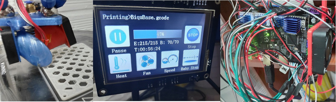
hectori4502
on 16 Feb 2019
You should not need to mess around with any of the SPI pins or edit the spi_pins.h file if you have the SD card settings configured correctly in your pins file. How do you actually want to use the SD card? What problem did you have to solve by using those settings? It would help if you provided your config files (including your modified pins file) and a full description of how you are trying to set things up.
As to having both SBase and SKR connected I don't think there should be a problem. What actual problems are you having? What connection is not working? What you may find is that the com port and/or shared drive letter that is used depends upon which device is connected first, but both should be available.
gloomyandy
on 16 Feb 2019
c
Actually anyone knows if there is a 32bit mcu board that can handle tmc2208 uart?
We have solved this problem.
bigtreetech
on 16 Feb 2019
@bigtreetech
How did you solved this?i want to use 4 tmc2208 uart and touch lcd..
weed2all
on 16 Feb 2019
Hi gloomyandy,
you're right
what I did not want to share the pin P1_23 (SS_PIN and X_CS_PIN)
I've already tried sharing pin P1_23 (SS_PIN and X_CS_PIN) and leaving original spi_pins.h and it works fine.
About the SD I had no problem because I use the SD of the TFT35
but the problem that did not let me move was the pin int + 5v usb which in my case needs to be in int + 5v (otherwise the motor does not move)
Thank you
hectori4502
on 16 Feb 2019
@hectori4502 so do you still have any problems?
gloomyandy
on 16 Feb 2019
@glomyandy everything is fine, I still want to solve an old problem that halt the printer when I sent the gcode M43.
Thank you.
hectori4502
on 17 Feb 2019
I'm pretty sure that M43 does not work with 32bit systems, at least some of the options on some of the systems, it is one of the many things on the long list of things to "tidy up".
gloomyandy
on 17 Feb 2019
c
Actually anyone knows if there is a 32bit mcu board that can handle tmc2208 uart?
We have solved this problem.
@bigtreetech , you have solved this problem on upcoming v1.2 board? Release still in March? Available via Amazon?
nordicblue
on 19 Feb 2019
sharing the pin P1_23 (SS_PIN and X_CS_PIN) the printer stop the trick to continue was to reconnect the host.
I move back to leave alone the pin P1_23 SS_PIN and use the pin P3_25 X_CS_PIN to solve it.
I did a test and it did not stop.
hectori4502
on 19 Feb 2019
@hectori4502 you should not be sharing P1_23 SS_PIN should not be defined if you are using it for CS. What display are you using? Are you trying to use the SD card reader attached to the display?
gloomyandy
on 19 Feb 2019
I'm using Biqu TFT35 with your SD.
hectori4502
on 19 Feb 2019
I thought it was settled to re-purpose the hardware enable line on each driver for CS?
Black6spdZ
on 19 Feb 2019
@Black6spdZ only if you are prepared to modify the driver modules and some/many people don't want to do that.
@hectori4502 it would probably help to see the pins file, did you have LPC_SD_LCD defined?
gloomyandy
on 19 Feb 2019
NO LCD
//#define USB_SD_DISABLED // Disable host access to SD card as mass storage device through USB
//#define USB_SD_ONBOARD // Enable host access to SD card as mass storage device through USB
//#define LPC_SD_LCD // Marlin uses the SD drive attached to the LCD
//#define LPC_SD_ONBOARD // Marlin uses the SD drive on the control board. There is no SD
//detect pin
hectori4502
on 20 Feb 2019
@hectori4502 Is there a reason for disabling access to the onboard SD card for Marlin and for USB? With the settings as you have them there is a chance that something may set things for you. I would suggest that you use the defaults of
#define  USB_SD_ONBOARD
#define USB_SD_ONBOARD
unless you have very good reason not to. The default settings don't use up any pins that are usable for other purposes. Do you have SDSUPPORT defined in your configuration.h file?
gloomyandy
on 20 Feb 2019
//#define SDSUPPORT //comment in my configuration.h file
I know it's a dirty way
What I'm looking for is activating these pins
#define X_CS_PIN P3_25
#define Y_CS_PIN P3_26
#define Z_CS_PIN P2_11
I know #define LPC_SD_LCD set this:
#define SCK_PIN P0_15
#define MISO_PIN P0_17
#define MOSI_PIN P0_18
hectori4502
on 20 Feb 2019
Sorry there was a mistake above the default settings are:
#define  USB_SD_ONBOARD
#define  LPC_SD_ONBOARD
Is there a reason why you are not using them? With this setting you can then define SDSUPPORT and use USB and/or Marlin to access the onboard SD card. USB access to this drive makes it much easier to perform firmware upgrades etc.
Then for your steppers define #define SKR_USE_LCD_PINS_FOR_CS which will set the following:
      #define X_CS_PIN      P1_23
      #define Y_CS_PIN      P3_26
      #define Z_CS_PIN      P2_11
      #define E0_CS_PIN     P3_25
      #define E1_CS_PIN     P1_31
This configuration has been used by others. Is there a reason why you do not want to use it? At the end of the day it probably doesn't matter so long as you have things working, but making changes like this will make it more difficult to update things in the future.
gloomyandy
on 20 Feb 2019
Cant post pics from my phone but i did a nice complete hardware mod on an older Gen-L to support 2130 SPI with no jumpers.. Plan to do it on the SKR soon
Black6spdZ
on 21 Feb 2019
You can if you set your phone to have webpage as a computer...
weed2all
on 21 Feb 2019
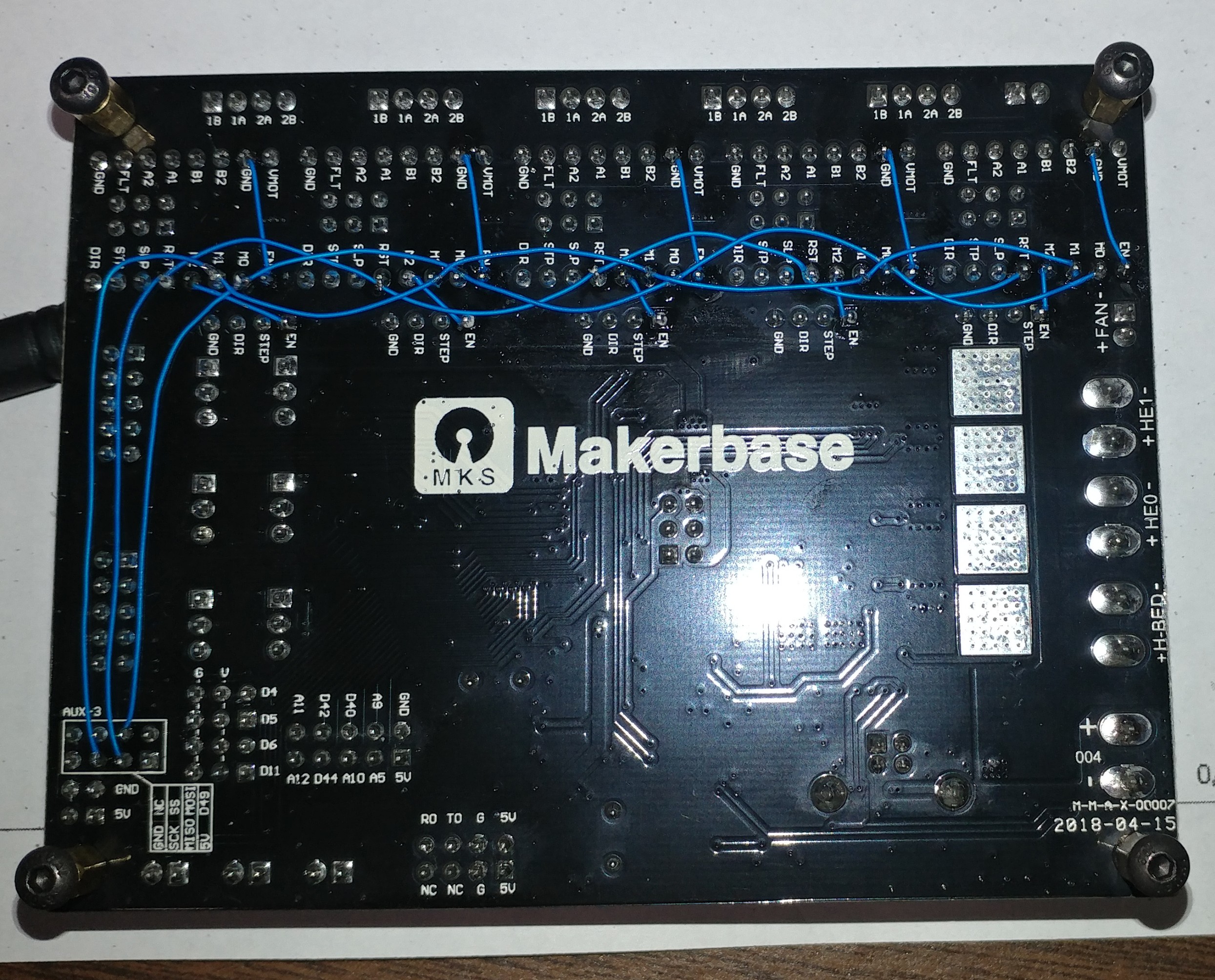
Black6spdZ
on 21 Feb 2019
Had to change browsers
Black6spdZ
on 21 Feb 2019
From wiring i understand the following:
EN->GND
M2->EN
Aux 3 port on mks gen L
SCK->M1(for all drivers)
MISO->RST(for all drivers)
MOSI->M0(for all drivers)
Is that right or I miss anything...
weed2all
on 21 Feb 2019
Traces on top of board were cut between en socket pin and en pin for ext driver along with all jumpers removed
Black6spdZ
on 21 Feb 2019
Yeah...i was wondering why did you use the external drivers en pin...that is connected to main en pin...lol...
weed2all
on 21 Feb 2019
That en external pin chip select pin that you used in config?
weed2all
on 21 Feb 2019
Black6spdZ
"Traces on top of board were cut between en socket pin and en pin for ext driver along with all jumpers removed"
My not being an electronics tech. What did you mean by the above phrase?
 Lightpainter1
on 21 Feb 2019
Lightpainter1
on 21 Feb 2019
@Lightpainter1
I cut the traces where you see the red marks.. this allowed me to pull the socket EN pin to ground "similar to @gloomyandy driver mod" then re-route the EN signal from the MPU to the CS pin on each socket on the back side. Working with wire wrap wire is a dream.. a few seconds from the iron tip melts through the jacket and connects it to the pin you want.. no stripping needed and you can make a continuous loop
I'm sure with SKR v1.2 they will implement some two position jumpers to accomplish this
Black6spdZ
on 21 Feb 2019
@weed2all problem solved?
 boelle
on 21 Feb 2019
boelle
on 21 Feb 2019
No man...still in testing
weed2all
on 22 Feb 2019
please click close an open new issue in the future
boelle
on 22 Feb 2019
Not wanting to escalate a meta-discussion but why close an on-topic discussion about how to get a board in a certain configuration running that’s is still active and being commented on nearly daily?
brandstaetter
on 22 Feb 2019
I think we have the github police in action...lol...
weed2all
on 22 Feb 2019
no just the cleaning vrew
boelle
on 22 Feb 2019
I agree I think we should keep this thread open as things are still being worked on.
gloomyandy
on 22 Feb 2019
same here, i make mistakes like everyone else
imagine going through 40 pages with 25 issues on each :-D
boelle
on 22 Feb 2019
Using Marlin bugfix-2.0.x, commit e15354e387cc825390fc4eaaf3ae4b784a8fd588
I have a few problems that I just can't seem to get my head around. Given some SKR oddities I've seen described elsewhere, regarding to how LCD, SD, and other things interact with one another, I assume the first few of these are connected. Apologies in advance if they're actually independent.
1. I do not have any kind of LCD or other display device on my printer, nor do I intend to get one yet (I'm content to manage things from my PC). However, if I do not enable at least some LCD support, or at least #define REPRAP_DISCOUNT_FULL_GRAPHIC_SMART_CONTROLLER, the SKR will not present the on-motherboard SD card to the host properly.
That is, dmesg reports a normal-looking connection, with device information, at first, but then it'll error out:
[  +0.000017] cdc_acm 3-3:1.0: ttyACM0: USB ACM device
[  +0.675909] usb 3-3: new full-speed USB device number 60 using ohci-pci
[  +0.195059] usb 3-3: New USB device found, idVendor=1d50, idProduct=6029
[  +0.000002] usb 3-3: New USB device strings: Mfr=1, Product=2, SerialNumber=3
[  +0.000001] usb 3-3: Product: Marlin USB Device
[  +0.000001] usb 3-3: Manufacturer: marlinfw.org
[  +0.000000] usb 3-3: SerialNumber: 1.0000000000
[  +0.002089] cdc_acm 3-3:1.0: ttyACM0: USB ACM device
[  +0.002104] usb-storage 3-3:1.2: USB Mass Storage device detected
[  +0.000549] scsi host9: usb-storage 3-3:1.2
[  +1.007401] scsi 9:0:0:0: Direct-Access     Marlin   Re-ARM SDCard 01 1.0  PQ: 0 ANSI: 0 CCS
[  +0.000427] sd 9:0:0:0: Attached scsi generic sg3 type 0
[  +0.009562] sd 9:0:0:0: [sdd] 245760 512-byte logical blocks: (126 MB/120 MiB)
[  +0.009996] sd 9:0:0:0: [sdd] Write Protect is off
[  +0.000002] sd 9:0:0:0: [sdd] Mode Sense: 03 00 00 00
[  +0.010001] sd 9:0:0:0: [sdd] No Caching mode page found
[  +0.000005] sd 9:0:0:0: [sdd] Assuming drive cache: write through

[  +1.462127] scsi_io_completion: 2 callbacks suppressed
[  +0.000005] sd 9:0:0:0: [sdd] tag#0 FAILED Result: hostbyte=DID_OK driverbyte=DRIVER_SENSE
[  +0.000003] sd 9:0:0:0: [sdd] tag#0 Sense Key : Not Ready [current]
[  +0.000002] sd 9:0:0:0: [sdd] tag#0 Add. Sense: Medium not present
[  +0.000002] sd 9:0:0:0: [sdd] tag#0 CDB: Read(10) 28 00 00 00 00 00 00 00 08 00
[  +0.000001] blk_update_request: 2 callbacks suppressed

[ ...it repeats these last 6 lines several times... ]

[  +0.027997]  sdd: unable to read partition table
[  +0.020010] sd 9:0:0:0: [sdd] Attached SCSI removable disk
At this point, there is nothing for me to mount, since it couldn't read the SD card's partition table, but I can still connect with Pronterface, and issue commands to the SKR. To recover, I have to put a good firmware.bin on the SD card using my PC's reader, then put it back in the SKR and reset (I kept a backup of the stock firmware, for just this sort of case).
Ok, so I enable it that option. Big deal, I don't actually have an LCD, so it's not like it's actually going to cause a problem, right?
Here's the dmesg output when that feature is enabled (when I disconnect the USB cable, then reconnect it):
[Feb24 11:46] usb 3-3: USB disconnect, device number 66
[Feb24 11:47] usb 3-3: new full-speed USB device number 67 using ohci-pci
[  +0.152014] usb 3-3: device descriptor read/64, error -62
[  +0.288026] usb 3-3: device descriptor read/64, error -62
[  +0.284035] usb 3-3: new full-speed USB device number 68 using ohci-pci
[  +0.152016] usb 3-3: device descriptor read/64, error -62
[  +0.260030] usb 3-3: device descriptor read/64, error -62
[  +0.108028] usb usb3-port3: attempt power cycle
[  +1.840158] usb 3-3: new full-speed USB device number 70 using ohci-pci
[  +0.227060] usb 3-3: New USB device found, idVendor=1d50, idProduct=6029
[  +0.000003] usb 3-3: New USB device strings: Mfr=1, Product=2, SerialNumber=3
[  +0.000001] usb 3-3: Product: Marlin USB Device
[  +0.000001] usb 3-3: Manufacturer: marlinfw.org
[  +0.000001] usb 3-3: SerialNumber: 1.0000000000
[  +0.002066] cdc_acm 3-3:1.0: ttyACM0: USB ACM device
[  +0.002103] usb-storage 3-3:1.2: USB Mass Storage device detected
[  +0.000128] scsi host9: usb-storage 3-3:1.2
[  +1.031836] scsi 9:0:0:0: Direct-Access     Marlin   Re-ARM SDCard 01 1.0  PQ: 0 ANSI: 0 CCS
[  +0.000426] sd 9:0:0:0: Attached scsi generic sg3 type 0
[  +0.009562] sd 9:0:0:0: [sdd] 245760 512-byte logical blocks: (126 MB/120 MiB)
[  +0.009995] sd 9:0:0:0: [sdd] Write Protect is off
[  +0.000003] sd 9:0:0:0: [sdd] Mode Sense: 03 00 00 00
[  +0.010003] sd 9:0:0:0: [sdd] No Caching mode page found
[  +0.000005] sd 9:0:0:0: [sdd] Assuming drive cache: write through
[  +4.833489]  sdd: sdd1
[  +0.045988] sd 9:0:0:0: [sdd] Attached SCSI removable disk
Looks fine to me, I guess... Either way, I can point a file manager at the on-board SD card, and connect to the SKR from Pronterface, like normal.
2. From what I understand, if I want to use TMC2208's in UART mode, I'd have to edit pins_BIQU_SKR_V1.1.h and add some pin defines for the drivers' UART lines. Of course, if I don't do that, the compiler will rightfully complain. Since I have no intent on adding an LCD, I assume the pins that would otherwise be used for one would be free. According to what I've read in a couple of places, Ports 0 and 2 of the LPC should be interrupt-capable, which is a necessity for the UARTs' RX lines, so, I've added the following to the aforementioned file:
#if HAS_DRIVER(TMC2208)
  #define X_SERIAL_TX_PIN  P0_15
  #define X_SERIAL_RX_PIN  P0_18

  #define Y_SERIAL_TX_PIN  P0_16
  #define Y_SERIAL_RX_PIN  P2_06

  #define Z_SERIAL_TX_PIN  P1_23
  #define Z_SERIAL_RX_PIN  P0_17

  #define E0_SERIAL_TX_PIN P3_25
  #define E0_SERIAL_RX_PIN P2_11

  #define E1_SERIAL_TX_PIN P1_03
  #define E1_SERIAL_RX_PIN P1_02
#endif
(I got this idea from another github thread, where I think @bigtreetech was working on a "v1.3" pins file to be used with the upcoming SKR v1.2)
The above X, Y, Z and E0 pins are all present on the "LCD/SD/SPI" header, some of which are also on EXP1/EXP2, while E1 is on the AUX1 connector if I understand things right. Of course, if I don't have an LCD, I should think this situation would be okay.
I hooked up the necessary patch wires, triple-checking my connections against the above pin assignments. Those patches are carried over from my previous controller (a common 2560/RAMPS stack), where they worked fine. I don't have an E1 driver, so there is no jumper wire present for that one.
Still, something ain't right. M122 gives me:
SENDING:M122
        X   Y   Z   E
Enabled     false   false   false   false

[... a bunch more normal-looking debug spew ...]

Driver registers:
        X   0x00:00:00:00    Bad response!
        Y   0x00:00:00:00    Bad response!
        Z   0x00:00:00:00    Bad response!
        E   0x00:00:00:00    Bad response!
Testing X connection... Error: All LOW
Testing Y connection... Error: All LOW
Testing Z connection... Error: All LOW
Testing E connection... Error: All LOW
So, what have I missed?
3. I have EEPROM support turned on, but M500 doesn't create an eeprom.dat file on the on-board SD card. Marlin does report echo:Settings Stored (591 bytes; crc 26020), however.
4. Maybe not related to the above: Pronterface's "Reset" button works fine on my old Ardiuno/RAMPS stack, but it does not trigger any kind of reboot on the SKR. Or if it does, Marlin's either ignoring it, or suppressing all of its normal bootup messages. The SKR's physical reset button works just fine, but naturally, if I hit that, it disconnects from USB. In short: There is no obvious way to see Marlin's usual bootup debug spew.
Configs: Marlin-configs-32bit-20190224.zip
The above file includes Configuration.h, Configuration_adv.h, src/pins/pins_BIQU_SKR_V1.1.h, platformio.ini (which needed a one-line change to make Atom's "[->]" button in the left button bar work), and a patch/diff that one can skim through, or apply over commit e15354e387cc825390fc4eaaf3ae4b784a8fd588.
Here's a photo of the hardware configuration, also:
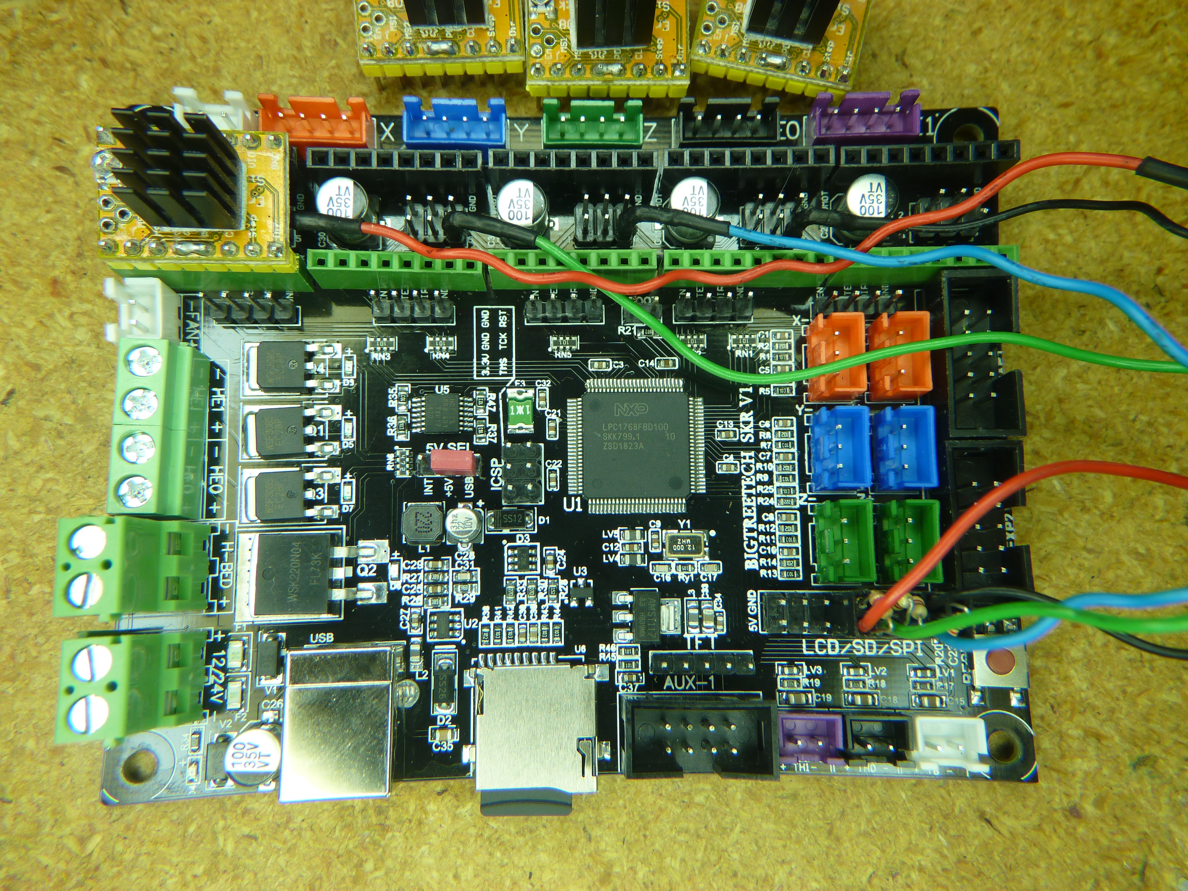
(the driver modules are all already set up for UART mode, with each UART pin routed so that it can be picked up from the motherboard's corresponding M0-M2 jumper header)
 VanessaE
on 24 Feb 2019
VanessaE
on 24 Feb 2019
- Don't even attempt to use UART support for TMC2208 for this board at the moment it will not work.
- eeprom support no longer uses a file on the SD card (and has not done so for around 6 months). It uses flash memory to emulate the eeprom.
- You can't use pronterfaces reset functionality with this (or any other LPC1768 based board). As it relies on the USB to UART chip present on most 8 bit boards for the functionality. This is not present when using the LPC1768 USB interface.
- Not sure what is going on with USB access to the SD card when you do not have a display defined. Does this problem still exist if you use stand along TMC2208 and remove all of the software serial pin defines?
gloomyandy
on 24 Feb 2019
Another thing that probably warrants its own topic is getting one-wire serial support for Marlin. There's no real need to use separate rx/tx pins, and it's all up to the softserial library used.
 jammi
on 24 Feb 2019
jammi
on 24 Feb 2019
@jammi See: https://github.com/MarlinFirmware/Marlin/issues/13197 it is already being worked on.
gloomyandy
on 24 Feb 2019
Hi all, just started to play with this board. Any idea if an I2C OLED display can be connected to this board?
 obertr0n
on 25 Feb 2019
obertr0n
on 25 Feb 2019
- Don't even attempt to use UART support for TMC2208 for this board at the moment it will not work.
Except in that fork in #13197 ?
- eeprom support no longer uses a file on the SD card (and has not done so for around 6 months). It uses flash memory to emulate the eeprom.
Ok, good to know (googling around for this sorta stuff is... not productive :stuck_out_tongue_closed_eyes: )
- You can't use pronterfaces reset functionality with this (or any other LPC1768 based board). As it relies on the USB to UART chip present on most 8 bit boards for the functionality. This is not present when using the LPC1768 USB interface.
Maybe I should pester @Kliment, then :smiley:
- Not sure what is going on with USB access to the SD card when you do not have a display defined. Does this problem still exist if you use stand along TMC2208 and remove all of the software serial pin defines?
With the four drivers set to TMC2208_STANDALONE, no pin defines, no drivers installed on the board, and UART jumpers disconnected -- i.e. on a completely bare/stock SKR board -- it still doesn't work if I disable that LCD option. Same errors as described above.
VanessaE
on 25 Feb 2019
With the four drivers set to
TMC2208_STANDALONE, no pin defines, no drivers installed on the board, and UART jumpers disconnected -- i.e. on a completely bare/stock SKR board -- it still doesn't work if I disable that LCD option. Same errors as described above.
Thanks for that, it will need looking into, but it is not very high priority for me at the moment. Note however that you can't just expect to define a display and then use the display pins for other things as Marlin will still use those pins even if you do not have an LCD connected. You could try adding the following:
#if ENABLED(ULTRA_LCD)
  #define BEEPER_PIN       P1_30
  #define BTN_EN1          P3_26
  #define BTN_EN2          P3_25
  #define BTN_ENC          P2_11

  #define SD_DETECT_PIN    P1_31
  #define LCD_SDSS         P1_23
  #define LCD_PINS_RS      P0_16
  #define LCD_PINS_ENABLE  P0_18
  #define LCD_PINS_D4      P0_15
#else`
  #define LCD_SDSS         -1
  #define LCD_PINS_RS      -1
  #define LCD_PINS_ENABLE  -1
  #define LCD_PINS_D4      -1
#endif
but I have not tried it.
By all means try things from the UART thread but be aware that the original solution has a number of problems that mean that there may be errors (that are not detected) when reading/writing to the TMC devices. The alternative code I've provided is definitely still in the experimental class.
Oh and the following pins:
  #define E1_SERIAL_TX_PIN P1_03
  #define E1_SERIAL_RX_PIN P1_02
are not interrupt capable. Did you intend to use P0_03 and P0_02?
gloomyandy
on 25 Feb 2019
@VanessaE Have been looking into your issue with USB access to the onboard SD card via USB when no display is defined. USB access is working fine, but in this configuration Marlin will mount the SD card (i.e. make it available to Marlin) when it boots. When you mount the card then the card can no longer be accessed via USB (as you will have two file systems updating the same block device). So to gain access to the card via USB you will need to tell Marlin to unmount it (issue an M22 from your host control program). When a display with a menu is available Marlin does not automatically mount the SD card and so it will be available vis USB. I'm not totally sure why things are setup this way, but no doubt there is a good reason!
gloomyandy
on 25 Feb 2019
That seems kinda..... well, dumb, to be perfectly honest. Either both conditions should lead to auto-mounting whichever SD card is present, or both should refrain from it (I strongly favor the latter).
In any case, your idea doesn't work for me -- turning off that option does not allow the host to read the onboard SD card, even after M22. The host OS just "sits there", unwilling to mount/read the card, I suppose because it tried when the SKR booted up, failed, and just gave up (and removing and re-inserting the card isn't enough to make the OS try again, probably because the SKR lacks a card sense line on the onboard slot).
VanessaE
on 25 Feb 2019
Well with no display defined it works fine for me with a windows host. On boot the card is not available to windows. After I issue an M22 the card appears as normal. Looks like you are using Linux, have you tried mounting the card manually after issuing the M22? My Octopi system never mounts the Marlin SD card automatically (with or without a display), but a manual mount works fine. No doubt there are options available to automate it, but I've never seen the need.
I'm sure you could hack the code to always refrain from mounting the sd card, but doubt if that would ever be the default case. Probably the code to look at is this...
https://github.com/MarlinFirmware/Marlin/blob/bugfix-2.0.x/Marlin/src/Marlin.cpp#L1064
gloomyandy
on 26 Feb 2019
Linux, yes. dmesg shows that the OS receives no indication that the volume has been cycled/"inserted" when I issue M22.
Here's such a session:
Log output
[  +0.000021] cdc_acm 3-3:1.0: ttyACM0: USB ACM device

[  +1.315985] usb 3-3: new full-speed USB device number 80 using ohci-pci

[  +0.199036] usb 3-3: New USB device found, idVendor=1d50, idProduct=6029

[  +0.000002] usb 3-3: New USB device strings: Mfr=1, Product=2, SerialNumber=3

[  +0.000002] usb 3-3: Product: Marlin USB Device

[  +0.000001] usb 3-3: Manufacturer: marlinfw.org

[  +0.000001] usb 3-3: SerialNumber: 1.0000000000

[  +0.002072] cdc_acm 3-3:1.0: ttyACM0: USB ACM device

[  +0.002108] usb-storage 3-3:1.2: USB Mass Storage device detected

[  +0.000358] scsi host9: usb-storage 3-3:1.2

[  +1.023545] scsi 9:0:0:0: Direct-Access     Marlin   Re-ARM SDCard 01 1.0  PQ: 0 ANSI: 0 CCS

[  +0.000423] sd 9:0:0:0: Attached scsi generic sg3 type 0

[  +0.009547] sd 9:0:0:0: [sdd] 245760 512-byte logical blocks: (126 MB/120 MiB)

[  +0.010010] sd 9:0:0:0: [sdd] Write Protect is off

[  +0.000003] sd 9:0:0:0: [sdd] Mode Sense: 03 00 00 00

[  +0.010019] sd 9:0:0:0: [sdd] No Caching mode page found

[  +0.000004] sd 9:0:0:0: [sdd] Assuming drive cache: write through

[  +0.262982] scsi_io_completion: 2 callbacks suppressed

[  +0.000005] sd 9:0:0:0: [sdd] tag#0 FAILED Result: hostbyte=DID_OK driverbyte=DRIVER_SENSE

[  +0.000003] sd 9:0:0:0: [sdd] tag#0 Sense Key : Not Ready [current]

[  +0.000002] sd 9:0:0:0: [sdd] tag#0 Add. Sense: Medium not present

[  +0.000002] sd 9:0:0:0: [sdd] tag#0 CDB: Read(10) 28 00 00 00 00 00 00 00 08 00

[  +0.000001] blk_update_request: 2 callbacks suppressed

[  +0.000001] blk_update_request: I/O error, dev sdd, sector 0

[  +0.000004] buffer_io_error: 2 callbacks suppressed

[  +0.000001] Buffer I/O error on dev sdd, logical block 0, async page read

[  +0.013975] sd 9:0:0:0: [sdd] tag#0 FAILED Result: hostbyte=DID_OK driverbyte=DRIVER_SENSE

[  +0.000002] sd 9:0:0:0: [sdd] tag#0 Sense Key : Not Ready [current]

[  +0.000002] sd 9:0:0:0: [sdd] tag#0 Add. Sense: Medium not present

[  +0.000001] sd 9:0:0:0: [sdd] tag#0 CDB: Read(10) 28 00 00 00 00 00 00 00 08 00

[  +0.000002] blk_update_request: I/O error, dev sdd, sector 0

[  +0.000002] Buffer I/O error on dev sdd, logical block 0, async page read

[  +0.013992] sd 9:0:0:0: [sdd] tag#0 FAILED Result: hostbyte=DID_OK driverbyte=DRIVER_SENSE

[  +0.000002] sd 9:0:0:0: [sdd] tag#0 Sense Key : Not Ready [current]

[  +0.000002] sd 9:0:0:0: [sdd] tag#0 Add. Sense: Medium not present

[  +0.000002] sd 9:0:0:0: [sdd] tag#0 CDB: Read(10) 28 00 00 00 00 00 00 00 08 00

[  +0.000001] blk_update_request: I/O error, dev sdd, sector 0

[  +0.000003] Buffer I/O error on dev sdd, logical block 0, async page read

[  +0.013990] sd 9:0:0:0: [sdd] tag#0 FAILED Result: hostbyte=DID_OK driverbyte=DRIVER_SENSE

[  +0.000002] sd 9:0:0:0: [sdd] tag#0 Sense Key : Not Ready [current]

[  +0.000002] sd 9:0:0:0: [sdd] tag#0 Add. Sense: Medium not present

[  +0.000002] sd 9:0:0:0: [sdd] tag#0 CDB: Read(10) 28 00 00 00 00 00 00 00 08 00

[  +0.000001] blk_update_request: I/O error, dev sdd, sector 0

[  +0.000003] Buffer I/O error on dev sdd, logical block 0, async page read

[  +0.000017] ldm_validate_partition_table(): Disk read failed.

[  +0.013995] sd 9:0:0:0: [sdd] tag#0 FAILED Result: hostbyte=DID_OK driverbyte=DRIVER_SENSE

[  +0.000002] sd 9:0:0:0: [sdd] tag#0 Sense Key : Not Ready [current]

[  +0.000002] sd 9:0:0:0: [sdd] tag#0 Add. Sense: Medium not present

[  +0.000002] sd 9:0:0:0: [sdd] tag#0 CDB: Read(10) 28 00 00 00 00 00 00 00 08 00

[  +0.000001] blk_update_request: I/O error, dev sdd, sector 0

[  +0.000004] Buffer I/O error on dev sdd, logical block 0, async page read

[  +0.013971] sd 9:0:0:0: [sdd] tag#0 FAILED Result: hostbyte=DID_OK driverbyte=DRIVER_SENSE

[  +0.000002] sd 9:0:0:0: [sdd] tag#0 Sense Key : Not Ready [current]

[  +0.000002] sd 9:0:0:0: [sdd] tag#0 Add. Sense: Medium not present

[  +0.000002] sd 9:0:0:0: [sdd] tag#0 CDB: Read(10) 28 00 00 00 00 00 00 00 08 00

[  +0.000001] blk_update_request: I/O error, dev sdd, sector 0

[  +0.000003] Buffer I/O error on dev sdd, logical block 0, async page read

[  +0.013979] sd 9:0:0:0: [sdd] tag#0 FAILED Result: hostbyte=DID_OK driverbyte=DRIVER_SENSE

[  +0.000002] sd 9:0:0:0: [sdd] tag#0 Sense Key : Not Ready [current]

[  +0.000002] sd 9:0:0:0: [sdd] tag#0 Add. Sense: Medium not present

[  +0.000002] sd 9:0:0:0: [sdd] tag#0 CDB: Read(10) 28 00 00 00 00 00 00 00 08 00

[  +0.000001] blk_update_request: I/O error, dev sdd, sector 0

[  +0.000003] Buffer I/O error on dev sdd, logical block 0, async page read

[  +0.014001] sd 9:0:0:0: [sdd] tag#0 FAILED Result: hostbyte=DID_OK driverbyte=DRIVER_SENSE

[  +0.000002] sd 9:0:0:0: [sdd] tag#0 Sense Key : Not Ready [current]

[  +0.000002] sd 9:0:0:0: [sdd] tag#0 Add. Sense: Medium not present

[  +0.000002] sd 9:0:0:0: [sdd] tag#0 CDB: Read(10) 28 00 00 00 00 00 00 00 08 00

[  +0.000001] blk_update_request: I/O error, dev sdd, sector 0

[  +0.000003] Buffer I/O error on dev sdd, logical block 0, async page read

[  +0.000016] Dev sdd: unable to read RDB block 0

[  +0.013973] sd 9:0:0:0: [sdd] tag#0 FAILED Result: hostbyte=DID_OK driverbyte=DRIVER_SENSE

[  +0.000002] sd 9:0:0:0: [sdd] tag#0 Sense Key : Not Ready [current]

[  +0.000002] sd 9:0:0:0: [sdd] tag#0 Add. Sense: Medium not present

[  +0.000002] sd 9:0:0:0: [sdd] tag#0 CDB: Read(10) 28 00 00 00 00 00 00 00 08 00

[  +0.000001] blk_update_request: I/O error, dev sdd, sector 0

[  +0.000003] Buffer I/O error on dev sdd, logical block 0, async page read

[  +0.013992] sd 9:0:0:0: [sdd] tag#0 FAILED Result: hostbyte=DID_OK driverbyte=DRIVER_SENSE

[  +0.000002] sd 9:0:0:0: [sdd] tag#0 Sense Key : Not Ready [current]

[  +0.000002] sd 9:0:0:0: [sdd] tag#0 Add. Sense: Medium not present

[  +0.000002] sd 9:0:0:0: [sdd] tag#0 CDB: Read(10) 28 00 00 00 00 00 00 00 08 00

[  +0.000001] blk_update_request: I/O error, dev sdd, sector 0

[  +0.000002] Buffer I/O error on dev sdd, logical block 0, async page read

[  +0.028003]  sdd: unable to read partition table

[  +0.020013] sd 9:0:0:0: [sdd] Attached SCSI removable disk

[Feb25 17:37] sd 9:0:0:0: [sdd] 245760 512-byte logical blocks: (126 MB/120 MiB)
.
Near the end, I issued M22 but it did nothing. Linux made one attempt to read the partition table, and failed. Therefore, there's nothing for Linux to mount, manually or otherwise. I can only assume that Windows just keeps re-trying as long as the volume appears to be present.
The problem as I see it, is that Marlin both auto-mounts the card for itself and makes it visible to the OS, on bootup of the SKR. If Marlin is going to auto-mount the card, fine, but then it should not make it visible to the OS at all.
VanessaE
on 26 Feb 2019
Did you try manually mounting the device? It looks like your dmesg log is reporting that a 126MB disk has been detected (see the last few entries in the log), probably after you issued the M22. Certainly linux can see the card reader device (which is basically what Marlin exports) and is correctly reporting that no media is present after Marlin has mounted the device. Think of it as what happens if you have a card reader and then remove the card from it. The m22 is the equivalent if inserting the card back into it.
I've just tried it on my Linux system and was able to mount the drive no problem after issuing the m22...
[2793509.026904] usb 1-1.3: new full-speed USB device number 43 using dwc_otg
[2793509.160709] usb 1-1.3: New USB device found, idVendor=1d50, idProduct=6029
[2793509.160863] usb 1-1.3: New USB device strings: Mfr=1, Product=2, SerialNumber=3
[2793509.160872] usb 1-1.3: Product: Marlin USB Device
[2793509.160880] usb 1-1.3: Manufacturer: marlinfw.org
[2793509.160887] usb 1-1.3: SerialNumber: 1.0000000000
[2793509.172678] cdc_acm 1-1.3:1.0: ttyACM0: USB ACM device
[2793509.179794] usb-storage 1-1.3:1.2: USB Mass Storage device detected
[2793509.181257] scsi host0: usb-storage 1-1.3:1.2
[2793510.200221] scsi 0:0:0:0: Direct-Access     Marlin   Re-ARM SDCard 01 1.0  PQ: 0 ANSI: 0 CCS
[2793510.209396] sd 0:0:0:0: [sda] 15351808 512-byte logical blocks: (7.86 GB/7.32 GiB)
[2793510.212289] sd 0:0:0:0: [sda] Write Protect is off
[2793510.212311] sd 0:0:0:0: [sda] Mode Sense: 00 00 00 00
[2793510.214838] sd 0:0:0:0: [sda] Asking for cache data failed
[2793510.214859] sd 0:0:0:0: [sda] Assuming drive cache: write through
[2793510.236610] sd 0:0:0:0: Attached scsi generic sg0 type 0
[2793511.925001] sd 0:0:0:0: [sda] tag#0 UNKNOWN(0x2003) Result: hostbyte=0x00 driverbyte=0x08
[2793511.925050] sd 0:0:0:0: [sda] tag#0 Sense Key : 0x2 [current]
[2793511.925081] sd 0:0:0:0: [sda] tag#0 ASC=0x3a ASCQ=0x0
[2793511.925101] sd 0:0:0:0: [sda] tag#0 CDB: opcode=0x28 28 00 00 00 00 00 00 00 08 00
[2793511.925116] print_req_error: I/O error, dev sda, sector 0
[2793511.925133] Buffer I/O error on dev sda, logical block 0, async page read
[2793511.930604] sd 0:0:0:0: [sda] tag#0 UNKNOWN(0x2003) Result: hostbyte=0x00 driverbyte=0x08
[2793511.930647] sd 0:0:0:0: [sda] tag#0 Sense Key : 0x2 [current]
[2793511.930662] sd 0:0:0:0: [sda] tag#0 ASC=0x3a ASCQ=0x3
[2793511.930694] sd 0:0:0:0: [sda] tag#0 CDB: opcode=0x28 28 00 00 00 00 00 00 00 08 00
[2793511.930708] print_req_error: I/O error, dev sda, sector 0
[2793511.930723] Buffer I/O error on dev sda, logical block 0, async page read
[2793511.935454] sd 0:0:0:0: [sda] tag#0 UNKNOWN(0x2003) Result: hostbyte=0x00 driverbyte=0x08
[2793511.935474] sd 0:0:0:0: [sda] tag#0 Sense Key : 0x2 [current]
[2793511.935486] sd 0:0:0:0: [sda] tag#0 ASC=0x3a ASCQ=0x3
[2793511.935501] sd 0:0:0:0: [sda] tag#0 CDB: opcode=0x28 28 00 00 00 00 00 00 00 08 00
[2793511.935510] print_req_error: I/O error, dev sda, sector 0
[2793511.935556] Buffer I/O error on dev sda, logical block 0, async page read
[2793511.935668]  sda: unable to read partition table
[2793511.941560] sd 0:0:0:0: [sda] Attached SCSI removable disk
[2793615.961099] sd 0:0:0:0: [sda] 15351808 512-byte logical blocks: (7.86 GB/7.32 GiB)
[2793615.982897]  sda: sda1
pi@octopi:~ $ sudo mount /dev/sda1 /mnt
pi@octopi:~ $ ls /mnt
Android                     S3_e3dfanduct.gcode
FIRMWARE.CUR                S3_Extrusion_Test.gcode
FOUND.000                   S3_FGSC_front.gcode
FOUND.001                   S3_k010xyzCalibration_cubepg.gcode
kfactor2.gcode              S3_Rubber_Duck.gcode
kfactor.gcode               S3_sbase-cover.gcode
LOST.DIR                    S3_sbase-support1.gcode
pgkfactor.gcode             S3_sbase-support2.gcode
plkfactor.gcode             S3_SwitchCover.gcode
S3_3DBenchy.gcode           s3_test.gcode
S3_3DBenchypg.gcode         S3_Tolerance Test V2 Final Makersmuse.gcode
S3_BCGens.gcode             S3_xyzCalibration_cube.gcode
S3_BCTreks.gcode            steptest.gcode
S3_bike-light-cover2.gcode  System Volume Information
pi@octopi:~ $
Really this is no different to what will happen when you issue an M21 followed by an M22 and Linux seems to handle that fine (at least I've not seen any reports of problems). But if you don't like the way that Marlin handles the boot situation then it should be easy to change the line I pointed out above.
Oh and one other thing is that if the SD card you are using is the one that comes with the SKR board then I would try something else as I've seen a number of people have issues with using that card via USB.
gloomyandy
on 26 Feb 2019
Did you try manually mounting the device
Again, the host can't read the partition table, so there is no volume to mount. And yes, it's the card that came with the SKR, and is the only one I have available right now.
But, just to be sure, I tried again. Disabled that LCD option, booted, got the same sequence of messages as before. Issued M22 and one line appeared:
[Feb25 19:58] sd 9:0:0:0: [sdd] 245760 512-byte logical blocks: (126 MB/120 MiB)
The card is visible in /proc/partitions:
8 48 122880 sdd
...and that's it. The OS did not try to re-read the partition table, so there's no sdd1 entry. 5 minutes later, it's still sitting there.
If it's considered an unacceptable situation to have two devices try to mount the same filesystem, and Marlin insists on mounting the card at bootup, then under no circumstances should Marlin make it visible to the host at the same time, until after M22.
Furthermore, with the SKR still sitting in that "halfway" state,
vanessa@rainbird:~$ sudo partprobe /dev/sdd
[sudo] password for vanessa:
Error: Error opening /dev/sdd: No medium found
I've just dug out the card that came with my SKR and it shows similar problems to those you are seeing. None of the other SD cards I have (I tried five others of various sizes and makes) have any sort of issue. The same thing happens with my Windows system, the card is not accessible after an m22. I'm not sure what the actual specification of the card is (it has a very small capacity) it could be old/slow, perhaps there is some issue with the way that Marlin accesses it. I would suggest you try another card when you get chance.
gloomyandy
on 26 Feb 2019
Oh and with this card I can reproduce the problem when using a display an m21 followed by m22 results in the drive not re-appearing under windows. No other card I have does this. Whatever is going on it does not seem to need Marlin to mount the card at boot time to trigger it.
gloomyandy
on 26 Feb 2019
I dug out another SD card I just remembered I had. It's a Transcend 32 GB class 10 card, and reads as such when I M21, M22. Same problem as with the stock one, though -- no re-read of the partition table.
Did you actually try your tests with no LCD configured/enabled in the firmware?
VanessaE
on 26 Feb 2019
Yep with no LCD defined and every other card I have except the one that came with the SKR it works fine for me. The dmesg output I posted earlier was with this configuration. You can see the initial error with reading the partition table (because the media is no longer available), then at the end of the log you can see that after the M22 the card size is displayed, device sda1 is created and this device can be mounted. I'm not sure why my system rereads the partition table, but yours does not. But there are obviously differences in the two systems. You can see in the traces that how the sense data is presented is different (yours displays the sense data in text mine in hex). I'm using octopi 15.1 which has a kernel version of 4.14.34-v7+. What are you running?
With your 32GB card. If you define a display (or comment out the line I pointed you at earlier), so that the card does not get mounted at boot time by Marlin, what happens if you then use M21 followed by M22? Is the card mountable again after the M22 in this case?
gloomyandy
on 26 Feb 2019
I'm running Debian 9.8, kernel 4.9.0. With a display defined, and using the 32GB card:
Log output
--> Power-up
[ +38.638176] usb 3-3: new full-speed USB device number 102 using ohci-pci
[ +0.195091] usb 3-3: New USB device found, idVendor=1d50, idProduct=6029
[ +0.000003] usb 3-3: New USB device strings: Mfr=1, Product=2, SerialNumber=3
[ +0.000001] usb 3-3: Product: Marlin USB Device
[ +0.000001] usb 3-3: Manufacturer: marlinfw.org
[ +0.000001] usb 3-3: SerialNumber: 1.0000000000
[ +0.002046] cdc_acm 3-3:1.0: ttyACM1: USB ACM device
[ +0.002089] usb-storage 3-3:1.2: USB Mass Storage device detected
[ +0.000441] scsi host9: usb-storage 3-3:1.2
[ +1.031488] scsi 9:0:0:0: Direct-Access Marlin Re-ARM SDCard 01 1.0 PQ: 0 ANSI: 0 CCS
[ +0.000638] sd 9:0:0:0: Attached scsi generic sg3 type 0
[ +0.009316] sd 9:0:0:0: [sdd] 61863936 512-byte logical blocks: (31.7 GB/29.5 GiB)
[ +0.010004] sd 9:0:0:0: [sdd] Write Protect is off
[ +0.000003] sd 9:0:0:0: [sdd] Mode Sense: 03 00 00 00
[ +0.009996] sd 9:0:0:0: [sdd] No Caching mode page found
[ +0.000004] sd 9:0:0:0: [sdd] Assuming drive cache: write through
[ +3.626197] sdd: sdd1
[ +0.046004] sd 9:0:0:0: [sdd] Attached SCSI removable disk
--> My desktop environment (XFCE) auto-mounted sdd1 and opened it in a file manager (Thunar).
[ +11.061584] FAT-fs (sdd1): Volume was not properly unmounted. Some data may be corrupt. Please run fsck.
--> Issued M21
[Feb26 04:33] VFS: Dirty inode writeback failed for block device sdd1 (err=-5).
--> Issued M22
[Feb26 04:34] sd 9:0:0:0: [sdd] 61863936 512-byte logical blocks: (31.7 GB/29.5 GiB)
...and then, nothing. sdd1 does not re-appear.
VanessaE
on 26 Feb 2019
So you are using an older kernel, no idea if that has anything to do with the differences. You should probably fix the errors on the SD card by running fsck, so that we have a good base line. With a display enabled what happens if you boot Marlin, unmount the drive from linux (eject it or whatever), M21 then then M22. That is really the safe workflow. Though really the system should be able to cope with just having the drive disappear after all there is nothing stopping the user from simply removing it.
Though I am a little confused I thought that you had originally said that with a display defined things were working for you?
gloomyandy
on 26 Feb 2019
You should probably fix the errors on the SD card by running fsck,
Don't mind those errors - the result is the same either way. Been there, checked that. But, I went ahead and sorted them out and tried again, to no avail.
Though I am a little confused I thought that you had originally said that with a display defined things were working for you?
Yes. I don't print from SD, so I hadn't had occasion to use the M21/M22 commands until you mentioned them. In other words, the on-board SD is only useful to me as a place to put firmware updates, especially since I've only just gotten this thing going enough to print from USB (using my A4988's, which do quite well, incidentally).
what happens if you boot Marlin, unmount the drive from linux (eject it or whatever), M21 then then M22.
It does this:
[ +48.971093] usb 3-3: new full-speed USB device number 107 using ohci-pci

[  +0.223043] usb 3-3: New USB device found, idVendor=1d50, idProduct=6029

[  +0.000003] usb 3-3: New USB device strings: Mfr=1, Product=2, SerialNumber=3

[  +0.000002] usb 3-3: Product: Marlin USB Device

[  +0.000001] usb 3-3: Manufacturer: marlinfw.org

[  +0.000001] usb 3-3: SerialNumber: 1.0000000000

[  +0.002068] cdc_acm 3-3:1.0: ttyACM1: USB ACM device

[  +0.002103] usb-storage 3-3:1.2: USB Mass Storage device detected

[  +0.000459] scsi host9: usb-storage 3-3:1.2

[  +1.011475] scsi 9:0:0:0: Direct-Access     Marlin   Re-ARM SDCard 01 1.0  PQ: 0 ANSI: 0 CCS

[  +0.000541] sd 9:0:0:0: Attached scsi generic sg3 type 0

[  +0.009439] sd 9:0:0:0: [sdd] 61863936 512-byte logical blocks: (31.7 GB/29.5 GiB)

[  +0.010000] sd 9:0:0:0: [sdd] Write Protect is off

[  +0.000003] sd 9:0:0:0: [sdd] Mode Sense: 03 00 00 00

[  +0.009973] sd 9:0:0:0: [sdd] No Caching mode page found

[  +0.000005] sd 9:0:0:0: [sdd] Assuming drive cache: write through

[Feb26 05:40]  sdd: sdd1

[  +0.045995] sd 9:0:0:0: [sdd] Attached SCSI removable disk
[ +33.546702] sd 9:0:0:0: [sdd] 61863936 512-byte logical blocks: (31.7 GB/29.5 GiB)
[ +0.044005] sdd:
Though really the system should be able to cope with just having the drive disappear after all there is nothing stopping the user from simply removing it.
And in fact, it behaves fine in my PC's card reader. Plug in the 32GB card, let it mount and open the folder, then pull the card out without properly unmounting it... the PC naturally throws an error (one of those useless ones where some programmer didn't bother with human readability). Plug the card back into the PC's reader, the PC doesn't complain, it just mounts it and works fine.
Now if I do that using the SKR's onboard slot, without using M21/M22, thus treating the onboard slot as if it were a generic card reader, the PC doesn't notice that the card was removed, nor that it was re-inserted. I guess something scans the entire directory tree at the start, so all directories and files do show up (it has a bunch of music on it). Of course, the PC can't actually read any of them once the card's back in, nor would I expect it to.
VanessaE
on 26 Feb 2019
If you only want it for firmware then just comment out this line:
https://github.com/MarlinFirmware/Marlin/blob/bugfix-2.0.x/Marlin/src/Marlin.cpp#L1064
and don't define a display. Without that line Marlin will not attempt to mount the drive (I've just checked this).
 #if ENABLED(SDSUPPORT) && DISABLED(ULTRA_LCD)
    card.beginautostart();
  #endif
remove/comment out the card.beginautostart(); line.
So I assume that when you unmount the drive and then do m21/m22 the drive is still not usable? Does the sdd1 device exist?
For me if I unmount the drive before doing m21/m22 then everything is fine and I can remount the drive. If I do not unmount the drive, then following M21 the drive is still mounted and visible (but it is set into a read only error state), if I then use m22 then I can unmount the drive and remount it and it works fine. Similarly if I leave the drive mounted then do m21, then unmount the linux drive and then do m22 everything seems to work and I can remount the drive no problem. So basically for me things work pretty much as expected (as they do when using Windows).
As a final test I pulled out an old laptop that runs Ubuntu (14.04 I think!), with that and a display defined a file explorer window pops up on Marlin boot (as expected), if I use that to unmount the drive and then do an M21/M22 then after the M22 command a new file explorer window pops up. So again things are doing what I would expect.
Sorry I think I've taken this pretty much as far as I can at the moment. I have no easy way of running the same version of linux as you and I'm not able to reproduce the problem you are seeing with the versions of Linux I do have available. Perhaps there is some sort of bug/issue with the particular version you are using? I'm really not sure what is going on.
gloomyandy
on 26 Feb 2019
If you only want it for firmware then just comment out this line:
I don't intend to do that, because sooner or later I'm sure I'll find reason to print from SD, but you're totally missing the point.
So I assume that when you unmount the drive and then do m21/m22 the drive is still not usable? Does the sdd1 device exist?
As I said, sdd1 does not exist after M21/M22, whether or not a display is defined.
Sorry I think I've taken this pretty much as far as I can at the moment.
The solution is painfully obvious to me: whatever Marlin is doing to make the onboard SD visible and mountable to the PC when a display that I don't even have is defined, it should do precisely the same without one. I simply do not see the confusion here.
VanessaE
on 26 Feb 2019
Let's take a step back here. I'm trying to help you and I don't think I'm missing the point.
I have already given you a way to get Marlin without a display to behave the same way as Marlin with a display. Comment out that one line. Then when Marlin boots you will have your SD card.
But that will not solve the issue of what happens following an M21/M22. From your reports it seems that for some reason the SD card is not seen correctly in this situation. Correct me if I am wrong but that will still be a problem for you?
I assume that the "obvious solution" is that after an M22 we should just do whatever Marlin is doing when it boots with a display? But in this situation it presents a totally new USB composite device. It is not possible to do that when you perform an M21/M22 as that will also disconnect the other half of the composite device which is the USB serial interface. Most people would not find that an acceptable solution.
gloomyandy
on 26 Feb 2019
Let's take a step back here. I'm trying to help you and I don't think I'm missing the point.
My point is this is behaving in a completely unintuitive and inconsistent manner.
What does an external display have to do with an on-motherboard SD card that's accessed through a different set of hardware lines?
I have already given you a way to get Marlin without a display to behave the same way as Marlin with a display. Comment out that one line. Then when Marlin boots you will have your SD card.
And what happens the next time I want to update? THAT's why I don't go editing the code, even to change one line. Sooner or later, that one-line change won't work anymore.
But that will not solve the issue of what happens following an M21/M22. From your reports it seems that for some reason the SD card is not seen correctly in this situation. Correct me if I am wrong but that will still be a problem for you?
For now, whether M21/M22 work doesn't matter to me, since I print via USB, but it's gonna matter to someone, and soon, because the SKR isn't that old of a board, and it appears to be in high demand. I can't be the only person for whom this doesn't work.
I assume that the "obvious solution" is that after an M22 we should just do whatever Marlin is doing when it boots with a display?
No, M21/M22 are a whole different matter, and I only care about bootup behavior right now. Marlin should just boot up without mounting the onboard SD card if there's no display defined, just as it does if there is an LCD defined and connected, with an SD card inserted. In other words, treat the two SD card methods as identical at bootup.
What happens after bootup is a completely different issue and is not what I'm complaining about.
VanessaE
on 26 Feb 2019
If you want to change the way that Marlin handles the SD card on boot without a display, then you should create a new issue just for that and you will have to get @thinkyhead to agree that such a change makes sense. Or just go ahead and create the PR and have the discussion that way. That issue is not specific to this board.
The thing is that Marlin will mount the SD card in an LCD based reader most of the time. The only reason you are not seeing that is because in this case no pin is defined that can detect if an SD card is present in the reader. If such a pin was defined and there was an SD card in the reader then Marlin would mount it, just like it is mounting the SD card with no display defined. Yes it is inconsistent but arguably it is the case of a display with no SD detect defined that is the odd one out.
For me the M21/M22 problem is a more important one. But as I said I can't reproduce that at the moment and so far it seems to be specific to your setup.
gloomyandy
on 26 Feb 2019
Well if it's all about the lack of a detect line, then sure, the focus should be on making M21/M22 work properly. I can accept that.
VanessaE
on 26 Feb 2019
Looks like the 1.3 version is now available for pre-order: https://www.aliexpress.com/item/Presale-BIGTREETECH-SKR-V1-3-Control-Board-32-Bit-CPU-Smoothieboard-MKS-GEN-L-GEN-V1/32981807406.html.
It looks like the general GPIO pin connector originally labeled "LCD/SD/SPI" is now dedicated to running the TMC drivers - unfortunately the documentation on the sale page doesn't say which processor pins correspond in case you want to use them as GPIO. I don't use TMC so would rather have the GPIO for RGB lights and PS_ON_PIN.
 ManuelMcLure
on 3 Mar 2019
ManuelMcLure
on 3 Mar 2019
You can find more info for v1.3: https://github.com/bigtreetech/BIGTREETECH-SKR-V1.3
And there is pins.h in offical marlin 2.0 branch for v1.3 too: https://github.com/MarlinFirmware/Marlin/blob/bugfix-2.0.x/Marlin/src/pins/pins_BIGTREE_SKR_V1.3.h
fape
on 3 Mar 2019
@ManuelMcLure that's not a pre-order. In fact, that's sold out. The entire first run of boards - without driver modules - was gone from that listing within just minutes of the release (someone likely just bought the entire lot, minus a couple of orders that others got in just in time, just to resell somewhere else).
I managed to grab one from one of BigTreeTech's other store listings (they posted several on their Facebook group).
VanessaE
on 3 Mar 2019
@fape Thanks for the link. Unfortunately unlike the SKR 1.1 wiring diagram the 1.3 diagram doesn't specify what processor pins correspond to which connector pins. For example, which connector pins correspond to the "special pins" at the end of the pins_BIGTREE_SKR_V1.3.h file? I just wish Bigtree had documented this better for those of us with "less standard" setups.
ManuelMcLure
on 3 Mar 2019
@ManuelMcLure it is documented: https://github.com/bigtreetech/BIGTREETECH-SKR-V1.3/blob/master/hardware/SKR-V1.3-PIN.pdf
VanessaE
on 3 Mar 2019
Ah - I was looking at those special pins to be available, but it looks like they're in use by the on-board SD and the LCD connectors, so not useful as GPIO as far as I can tell. I'm still unclear as to the pins labeled XST/YST/etc. (the ones just to the left of the EXT2 connector) - those don't seem to have pin numbers unless they are the same ones used by XCS/YCS/etc.
I'm just looking for 5 pins I can use for GPIO (RGBW and PS_ON_PIN) on a simple build replacing a RAMPS with A4988 drivers and a 12864 LCD.
I suppose I can always get a board and probe with my multimeter...
ManuelMcLure
on 3 Mar 2019
I think you will find that the YST/XST pins are pin headers to allow the bridging of the TMC DIAG pins to the end stop inputs for use with sensorless homing etc. I think the XCS/YCS do not really refer to a single header but are documenting the chip select pins that are probably connected via the jumper pins under each stepper driver.
Unfortunately although there are many more pins in use on this version of the board, these extra pins are not very easily accessible. If you are not using TMC2130 drivers then I suspect that you could use the various chip select pins but you may have to use a jumper wire that goes under one or more of the driver boards to get to it.
gloomyandy
on 3 Mar 2019
Oh and before this discussion gets any longer it may make sense to create a new issue for the 1.3 board, as this one is already pretty long and confusing!
gloomyandy
on 3 Mar 2019
Don't guess. Come an join our BIQU SKR User Group @
We have all available documentation online here, and would sincerely like your opinions.
Michael E. Burk
Admin
Lightpainter1
on 3 Mar 2019
@Lightpainter1 that would be great if FB allowed non-members to view.. I left that sh!t site a year ago and will never rejoin.
Black6spdZ
on 3 Mar 2019
Well FB doesn't, you can however turn off notifications. And your expertize would be most welcome.
Lightpainter1
on 4 Mar 2019
Hello anyone try to use e3d pt100 amplifier board on skr 1.1? For work the board Need +5v gnd and free analogic PIN ..
 dylanshock
on 4 Mar 2019
dylanshock
on 4 Mar 2019
hi everyone, sorry for my poor english...
I'm bought the SKR v1.3 , this LCD (Anet A8):
https://pt.aliexpress.com/store/product/2-PCS-Anet-2004-LCD-Smart-Display-Screen-Controller-Module-3D-Printer-Parts-for-RAMPS-1/3126008_32830879237.html?spm=a2g03.12010615.8148356.1.35973f9e6FoSkr
will it work?
thanks in advance
 antonvier
on 6 Mar 2019
antonvier
on 6 Mar 2019
This issue has been automatically locked since there has not been any recent activity after it was closed. Please open a new issue for related bugs.
![github-actions[bot] picture](https://avatars2.githubusercontent.com/in/15368?v=4&s=40) github-actions[bot]
on 16 Jul 2020
github-actions[bot]
on 16 Jul 2020
Related issues
 Kaibob2
·
4Comments
Kaibob2
·
4Comments
 jerryerry
·
4Comments
jerryerry
·
4Comments
 Bobsta6
·
3Comments
Bobsta6
·
3Comments
 W8KDB
·
4Comments
W8KDB
·
4Comments
 esenapaj
·
3Comments
esenapaj
·
3Comments
Most helpful comment
Alright, my config is here: link

The wiring is almost the same as thisiskeithb wrote, only the SDI and SDO is connected to the AUX1 port, and to clarify it even more, here's a pic, with the LCD wired in:
If this does not explain it well enough, then I seriously cannot help you.