Mapper: line segment length and angle on mobile version
krticka reported on Sourceforge [tickets:#398]:
One important function I am missing for mapping. Sometimes straight linear objects (narrow rides, minor water channels) are not visible in orthophoto, but I can find them in terrain, hidden under the trees. When I was mapping on desk, I measured directions of these straight objects, and draw their direction on the desk. Especially in case of many straight narrow rides it was helpful, you don't need to walk them all.
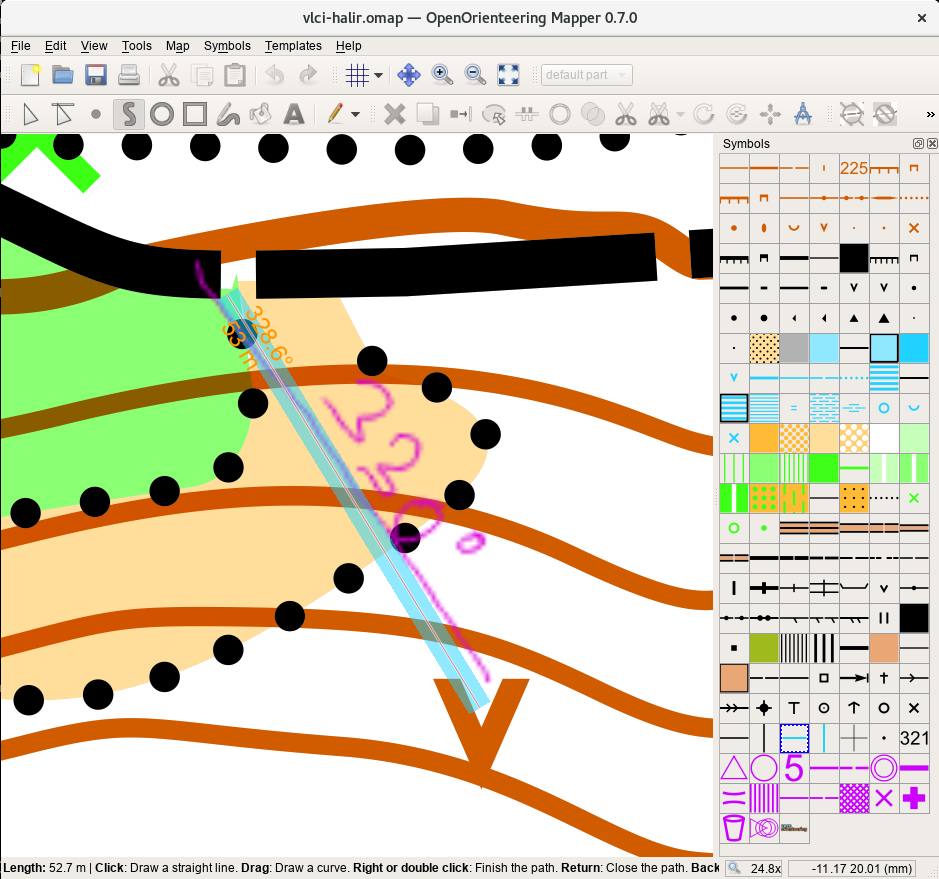
When I am drawing in mobile version I am missing such functionality. I can measure direcions (angle) of narrow rides with sighting compass, but how to precisely draw it in mobile Mapper? Solution can be to show length and angle of actual line segment when drawing, see attachment (sample is from desktop version).

 dg0yt
dg0yt
All 16 comments
Interesting idea.
We should also handle the case when editing an inner point in a multi-segment path. Another screenshot welcome :-)
Apart from this, would you like to enter the direction and distance directly, i.e. as text?
dg0yt
on 16 Sep 2014
Somebody posted on Sourceforge:
For editing inner point I would use illumination with different colors for segments and text information (see attachment). The question is, where to show such information, if in floating bubble or in some status bar in upper part of the screen. For sure I would allow to switch on/off this function in preferences, for some users who don't need it it can be annoying.
I don't think that entering direction and distance directly is so much needed (something like numeric mode in OCAD) it will be too slow to enter all the data, but other users can need it, I am not sure about this.

dg0yt
on 17 Sep 2014
Hi, I would also took advantage of this functionality. I am used to measure directions and distances precisely by compass with optical visor and laser range finder and draw it on a desk with protractor. I measure not only linear objects, but also distant point objects. It is possible to make an accurate map even without good templates. It's actually pretty quick because I do not have to perform additional repairs of drawing. In Ocad I can use numeric mode of drawing, but as proposed by krticka, viewing angle and distance lines when drawing a line would be propably quicker on tablet. It should be enough to display integers for reasonable accuracy. If it was easier, direct input of distance and angles would also be very helpful.
 Osin01
on 23 Aug 2016
Osin01
on 23 Aug 2016
Well, I must say that still I would like to see this functionality implemented (and quite many other users as I know). For example last two days I was working in valley with problematic GPS signal and with many features. Almost no information from orthophoto. The result is that I will need to switch to classic way of mapping with pens and mylar as I am not able to process this area properly with GPS signal only. Precise lengths and angles are still needed in my point of view.
 krticka
on 30 Oct 2016
krticka
on 30 Oct 2016
I have to agree with Osin01 and krticka. I moved from traditional way to digital way of mapping last year. Mentioned functionality is missing me. I consider such tool as very crucial and useful for field work mapping. There are many situations when GPS signal has problematic or unsufficient quality and further measurements like distance and azimuth between objects are needed.
 langrjan
on 21 Nov 2016
langrjan
on 21 Nov 2016
I would also like to highlight urgent need for functionality described in this issue. Especially in summer, GPS is quite unreliable not only in difficult terrain (rocks, ...) but also in a standard forest and the only way to make a reliable map is to measure distances and azimuth. To start, it would be sufficient if only for line objects drawn in straight-line mode, current line length and azimuth is displayed somewhere in the corner (with possibility to switch this off) as indicated on a screenshot of _krticka_. By drawing helping lines, one could place also point objects in this way. I also think that this way would be more comfortable for drawing on a tablet than a numeric mode.
 akom5224
on 12 May 2017
akom5224
on 12 May 2017
I have perhaps not the solution but at least a solution which I already tried in field when mapping with a mobile device and was quite happy with. I have added point symbols to my symbol set where each symbol provides a line (point where this "point symbol" is placed on a map = beginning of the line) with a given direction (azimuth). I have 360 of such symbols whose direction changes by 1 degree. The line corresponds to 100 m (on 1:10 000 map) and its color changes each 5 m. In this way, I can place objects with known values of both azimuth and distance from the reference point with still much better precision that what I could achieve using traditional tools like a protractor and a ruler on a desk. The only disadvantage I see is the fact that somehow too many symbols are now present in the symbol set. Nevertheless, even on a smartphone, all 360 degree symbols more or less fit on one screen and I only have to scroll between those symbols and "normal" map symbols. Nevertheless, perhaps, just half of azimuth symbols would be sufficient with changes by 2 degrees (especially when placing not too distant objects) to achieve reasonable precision.
Icons of my azimuth symbols are not really informative as they do not show the azimuth value. This could be improved if I knew how to change an icon of a symbol (if it is possible to define an icon different from a symbol - I do not know). For this reason, I have placed landmarks each 10 degrees in the symbol set. For those interested to try, here:
http://msekce.karlin.mff.cuni.cz/~komarek/OB/Azimuth.omap
you can download the symbols and copy-paste them to your map. Five colors must also be added (Azimuth color1 - Azimuth color5) which are present on top of the color list. The xml code which is behind the symbol set was created by a small programme that also calculates all necessary coordinates. So the symbols should provide correct azimuths (if I correctly implemented trigonometric rules ;-))

akom5224
on 22 May 2017
I've started surveying with a tablet and GPS and I'm missing the azimuth measuring capability in OOM. Given the experience from the field I've started looking into the thing and this would be my approach.
diff --git a/src/tools/draw_path_tool.cpp b/src/tools/draw_path_tool.cpp
index 9c6ccf872999..87d25cc2207a 100644
--- a/src/tools/draw_path_tool.cpp
+++ b/src/tools/draw_path_tool.cpp
@@ -1069,9 +1069,10 @@ void DrawPathTool::updateStatusText()

        if (editingInProgress() && preview_path && preview_path->getCoordinateCount() >= 2)
        {
-               //Q_ASSERT(!preview_path->isDirty());
-               float length = map()->getScaleDenominator() * preview_path->parts().front().path_coords.back().clen * 0.001f;
-               text = text + tr("<b>Length:</b> %1 m ").arg(QLocale().toString(length, 'f', 1)) + QLatin1String("| ");
+               // calculate length and angle from (constrained_pos_map - click_pos_map)
+               MapCoordF helperLine = constrained_pos_map - click_pos_map;
+               float angle = (atan2(-helperLine.x(), helperLine.y()) + M_PI) * 180 / M_PI;
+               text = text + tr("<b>Angle:</b> %1° ").arg(QLocale().toString(angle, 'f', 0)) + QLatin1String("| ");
        }

        if (draw_dash_points && !is_helper_tool
Angle information appears in the lower left window corner instead of the total line length.
This implementation is fine for the desktop UI version. Some different approach might have to be used for the mobile UI.
Comments and code contributions are welcome.
 lpechacek
on 26 Sep 2017
lpechacek
on 26 Sep 2017
First comments, before you prepare a PR:
- We probably don't want to drop the length.
- QLineF maybe a convenient tool for angle and length, now that MapCoordF is a QPointF.
- I also avoid direct use of M_PI, in favour of qRadiansToDegrees and friends.
- For Android, I use "toasts" for temporary information.
dg0yt
on 26 Sep 2017
Thanks for hints, Kai. Especially the part about QLineF was useful.
https://github.com/lpechacek/mapper/commit/bf4c5b0ca0d5ca3206339a46b7fa3512c3eb7795 is how I envision the feature to work. Azimuth and length displays along the line segment close to the cursor position. The code is not state of the art but works fine for the moment. As usual, comments are welcome.
lpechacek
on 2 Oct 2017
I'm a happy man...
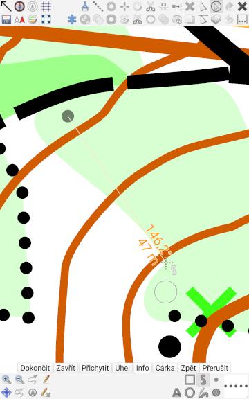
For those brave enough, Android test build is at liborpechacek.wz.cz/oomapper/mapper-issue398-g810b5d3.apk . It is based on the above pull request.
Azimuth feature is available only when drawing new paths and gets activated by clicking the _Info_ button. Another click or finishing the path deactivates the display. Looking forward to testing it in the field.
lpechacek
on 9 Oct 2017
Nice, I suggest that you can toggle between "no show", "azimut + length" and just "length".
 Zerbembasqwibo
on 9 Nov 2017
Zerbembasqwibo
on 9 Nov 2017
That would add one more touch in my use case.
lpechacek
on 10 Nov 2017
Can we close this particular issue?
dg0yt
on 5 Oct 2020
I think so.
krticka
on 5 Oct 2020
I also think that the issue has already been solved (some time ago), thanks.
Arnost
Op 10/5/20 om 9:41 AM schreef krticka:
I think so.
—
You are receiving this because you are subscribed to this thread.
Reply to this email directly, view it on GitHub
https://github.com/OpenOrienteering/mapper/issues/398#issuecomment-703460158,
or unsubscribe
https://github.com/notifications/unsubscribe-auth/AF4MQ2WR2MC35LNZRTHFWLTSJF2DVANCNFSM4CNJNGIA.
akom5224
on 5 Oct 2020
Related issues
 dl3sdo
·
5Comments
dl3sdo
·
5Comments
 jan-gerard
·
7Comments
jan-gerard
·
7Comments
 Symbian9
·
3Comments
Symbian9
·
3Comments
 sfroyen
·
6Comments
sfroyen
·
6Comments
 Abbe98
·
9Comments
Abbe98
·
9Comments
Most helpful comment
I'm a happy man...

For those brave enough, Android test build is at liborpechacek.wz.cz/oomapper/mapper-issue398-g810b5d3.apk . It is based on the above pull request.
Azimuth feature is available only when drawing new paths and gets activated by clicking the _Info_ button. Another click or finishing the path deactivates the display. Looking forward to testing it in the field.