Klipper: [FR] Add accelerometers support to Klipper for input shapers tuning
Accelerometers can be used to find resonances of the printer more accurately. More importantly, they can be used to find all resonances of the printer per axis, instead of only the strongest one using a test print. This can make it easier to tune input shapers.
TBH, I'm not sure what the demand for this feature is. Accelerometers (e.g. ADXL345) are not very expensive these days, and may be worth it given the time savings for tuning. However, they require some soldering and wiring - and not everyone is comfortable doing that. @KevinOConnor what's your take one this? Do you think this is something that makes sense to have support for in Klipper?
@BlackStump, @Sineos what is your feedback on the current implementation of this feature in adxl345-spi? It is admittedly relatively slow, because it has to run a test for multiple frequencies in a row. I'll see if that process can be improved using the suggestions from @nagimov. Alas, my initial experiments with FFT were not particularly successful - it sort of works, but lacks some robustness (and I'm sure the test process is not good, and I've been also likely making mistakes in how I put a non-periodic signal into FFT). It also appears that the results of the measurements with FFT do not exactly agree with the direct measurements of vibration response with accelerometer - the difference is not large, only a few Hz, but it is nonetheless not expected and quite suspicious. And direct measurements previously showed good agreement with the measurements using simple ringing test. Still, it is not clear which one is more accurate.
This is a dedicated ticket to discuss accelerometers support instead of #2030, which got too large.
 dmbutyugin
All 173 comments
I am using it on a dedicated Pi4 2Gb and have had it freeze a few times, I suspect that is a pigpiod issue as they mention pi4 support is experimental.
It does make tuning a lot easier and faster after the adxl345-spi is installed and as you mention they are cheap to buy.
As a tuning tool well worth it imho.
 BlackStump
on 28 Jun 2020
BlackStump
on 28 Jun 2020
Well, I'm a big fan of measuring things, so I think it is a fantastic addition:
- Tuning S-Curve parameters
- Assessing modification, like resonance pre and post modification
- Scientific interest
- Future: Quality guidance for printers - maybe a database could be setup to compare popular models in terms of their mechanical properties
Installation-wise, it is quite easy and can be done below 10 €/USD. There are even 50cm jumper cable available, which make it even easier. Hardest part is hitting the right pins on the RPi - good eyes and the ability to count surely help.
On my RPi3 I didn't experience any stability issues, running alongside Klipper and OctoPrint.
 Sineos
on 28 Jun 2020
Sineos
on 28 Jun 2020
@BlackStump To be fair, there could be some issues with the code stability. It was more like a proof of concept, and does require some rework and fixes. If you run into issues with it - feel free to report them here (and please attach the klippy.log). What I meant was that the code is quite promising and appears to be robust to measurement errors and has good repeatability of measurements - so it appears that we're not just measuring noise.
@Sineos As a follow-up from another thread: my feedback on the measurements after re-doing X axis is you do appear to have resonances. It is just that the test is not designed for very low frequency measurements, and gives bogus results at a few Hz, so the true resonances are lost if those values are not discarded. BTW, I have added now a low limit to the code to forbid measurements below 10 Hz, but realisticaly the good precision can be obtained starting from ~15 Hz I would say.
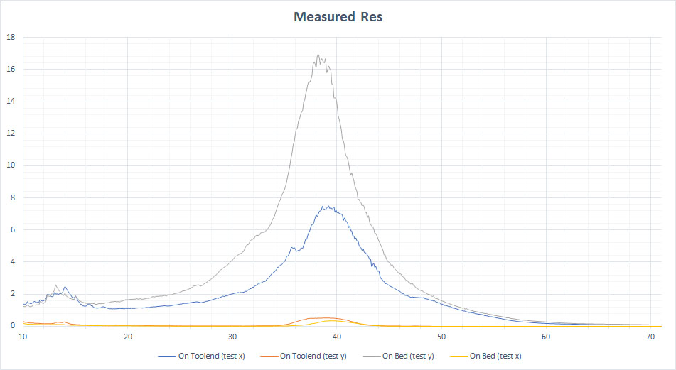
So, my conclusion is:
- X axis has a resonance at 71.5 Hz and a smaller one at ~49 Hz (and perhaps at 63 Hz).
- Y axis has a resonance at ~58 Hz.
If you end up trying input shapers tuned for these frequencies - please share how it goes. I guess for Y axis you could use 'ei' shaper tuned for 60 Hz and for X axis - 'ei' shaper tuned for 60 Hz (so just EI shaper at 60 Hz for both axes - this should be sufficient in your case), or '2hump_ei' for X axis at 65 Hz (the shapers can be configured per axis with shaper_type_x and shaper_type_y parameters).
dmbutyugin
on 28 Jun 2020
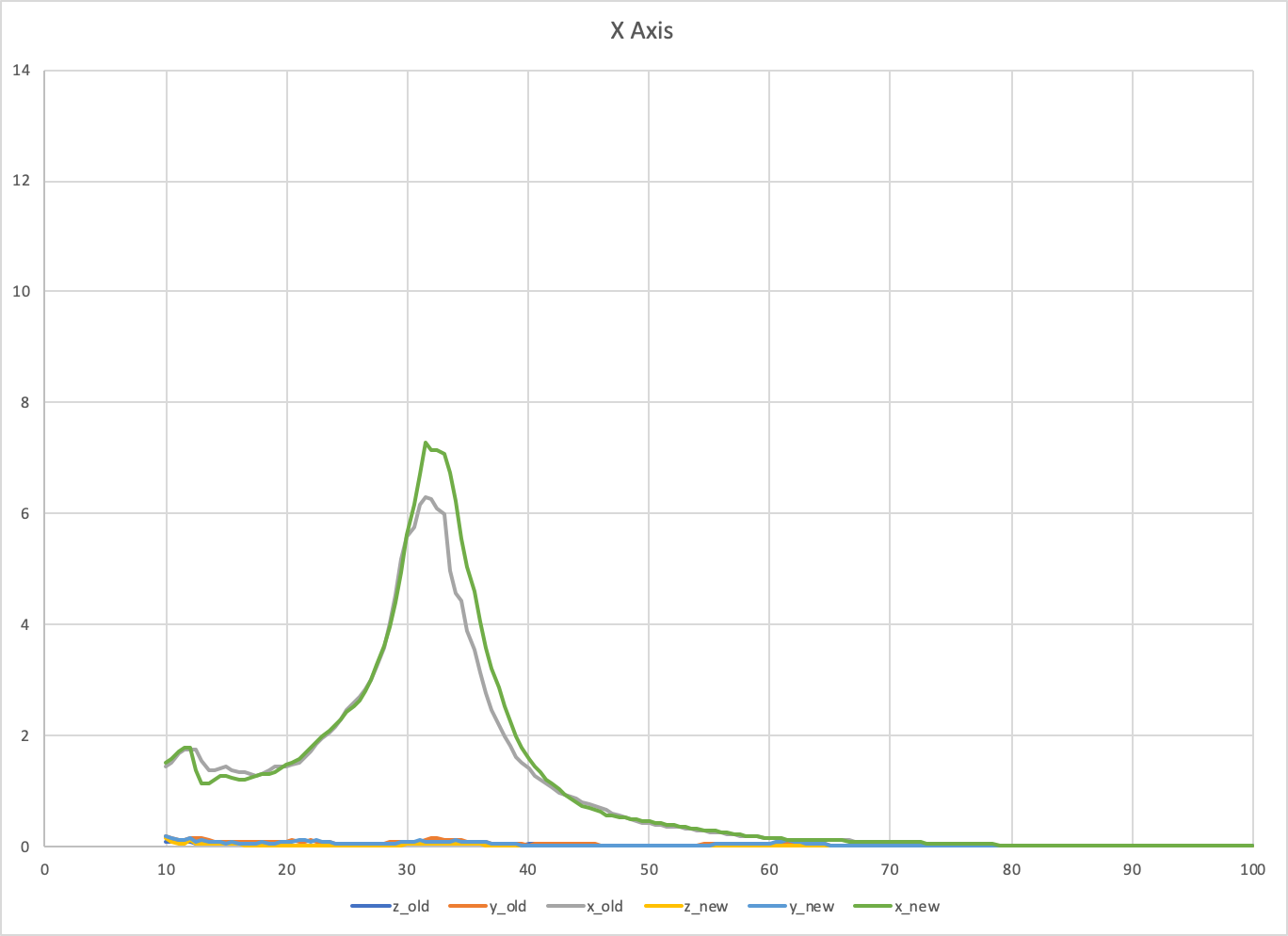
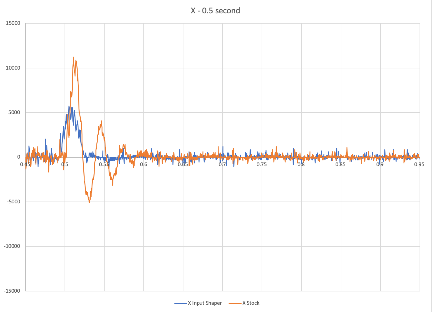
FYI, I moved the accelerometers on my m2 printer to locations closer to the carriages and reran some tests. The graphs below are the combination of two separate runs each (I graphed the two runs together to better show the overlap).
X axis: 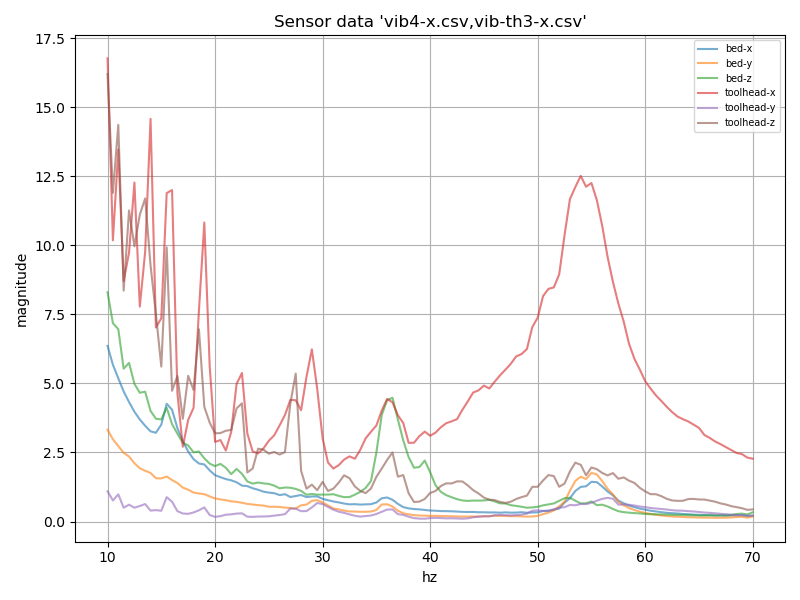
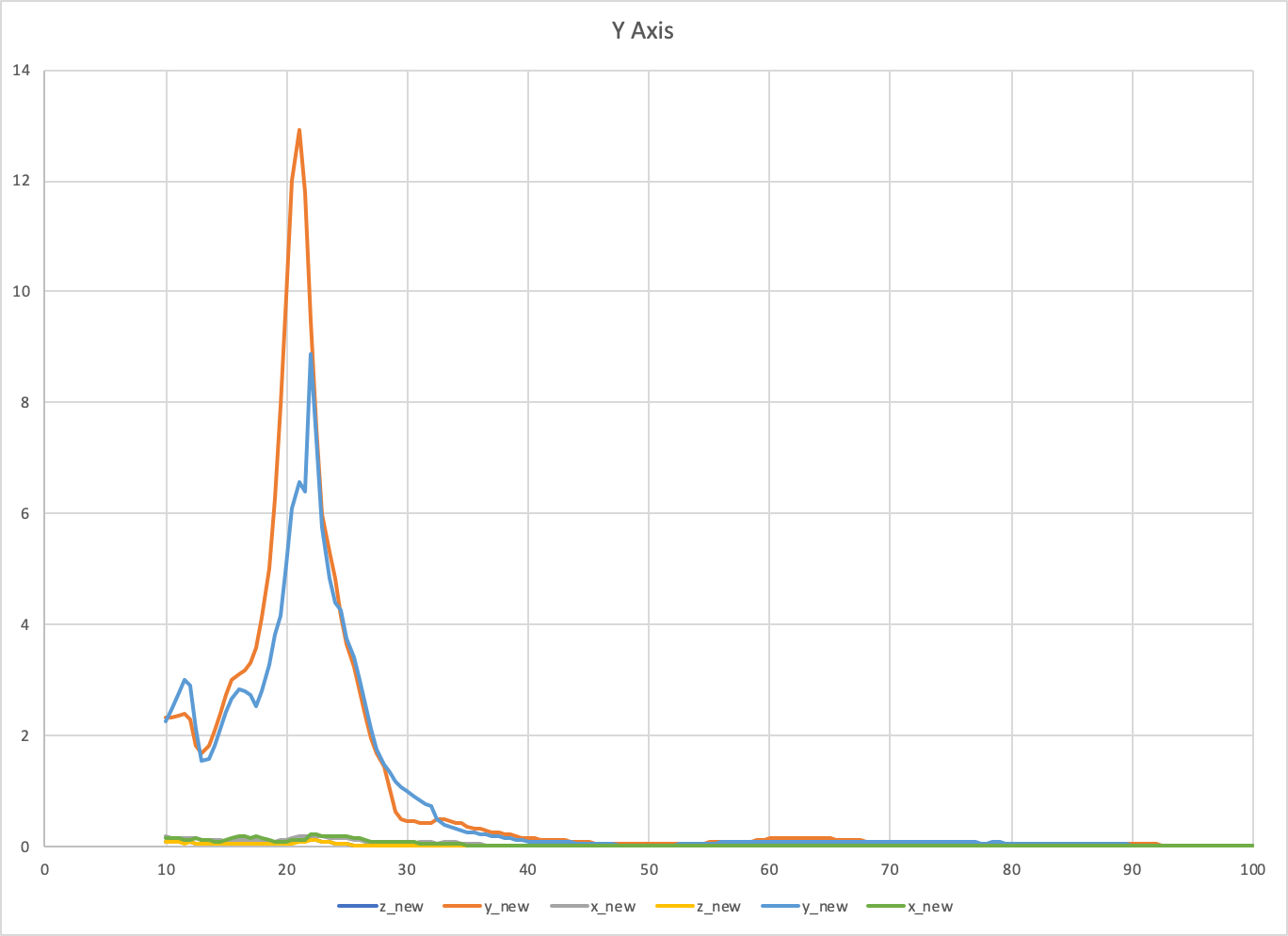
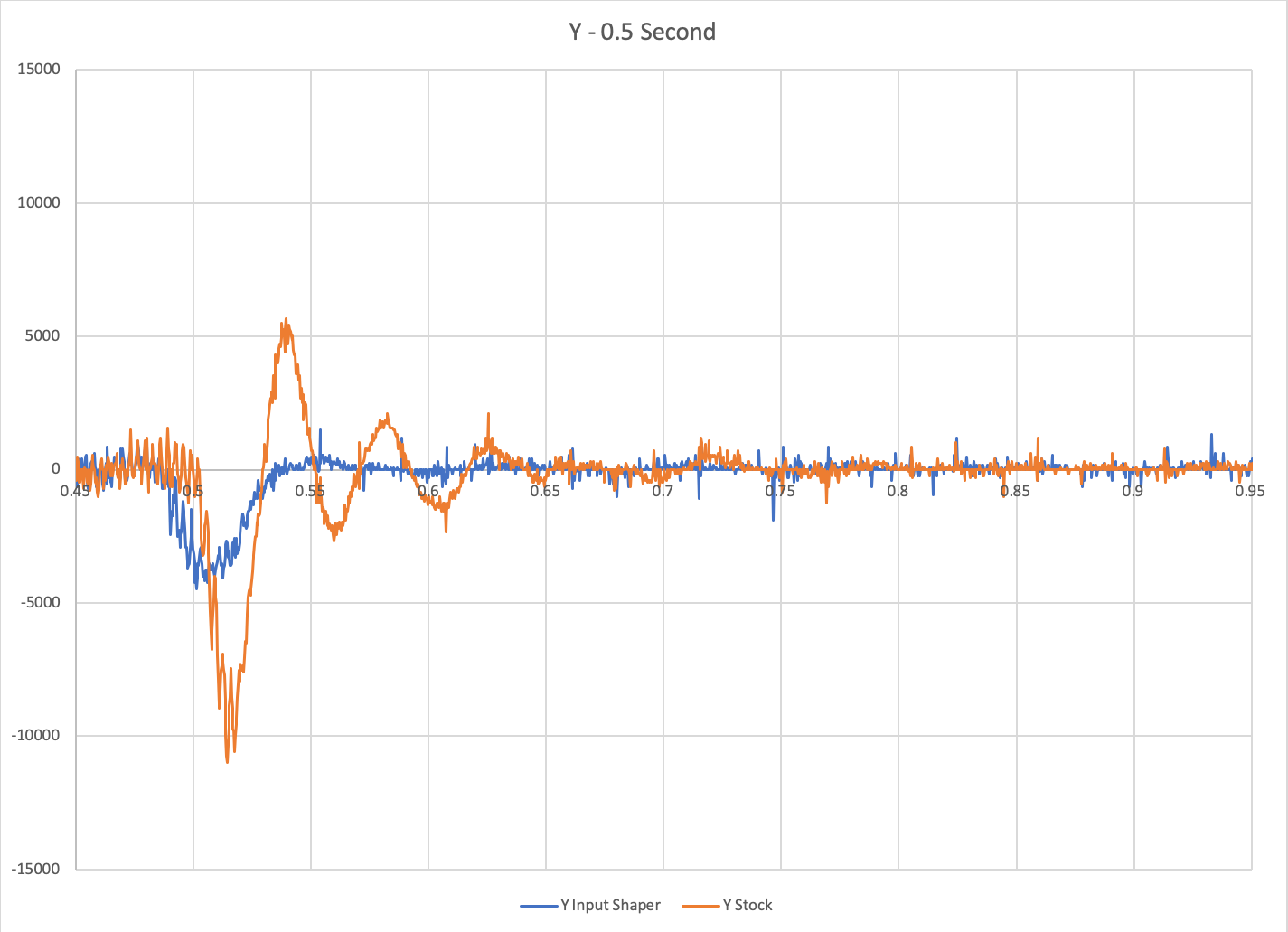
Y axis:
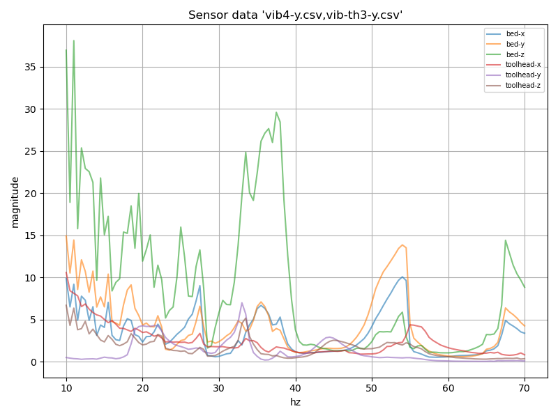
The results look more clean. I should run some more tests, but I suspect the X axis belt resonates at ~55hz while the X axis frame resonates at <10 hz . I suspect the Y axis belt also resonates at ~55hz. I suspect the linear Z rails holding the cantilevered bed have a tendency to resonate at ~35hz.
Some questions:
- If the X axis is being tested, does the code ensure that the y axis moves at constant speed? I suspect the slight 35hz Z axis vibration picked up by the bed accelerometer during the X axis test is due to slight changes in speed of the y. (And I have a similar suspicion on the 55Hz X axis toolhead vibration during the Y test.)
- Can you elaborate on what the Y axis is for these graphs? What units is it in and how is the measurement obtained?
-Kevin
EDIT: FYI, this was on code revision 2c9cd98e.
 KevinOConnor
on 28 Jun 2020
KevinOConnor
on 28 Jun 2020
Do you think this is something that makes sense to have support for in Klipper?
I think the functionality is very useful and great to have. However, given the requirement to solder, crimp, etc., and given that it requires wiring to an rpi, I'd say that it is currently only applicable to experts. As such, I'm "not in a rush" to merge it. (As I'd expect experts to also be able to pull down the separate branch with the test code.) Lets see what feedback we get and go from there.
Thanks.
-Kevin
KevinOConnor
on 28 Jun 2020
@dmbutyugin @KevinOConnor
It seems like lower end frequencies on FFT plots are a bit too noisy. This could be caused by too short recording times for FFT to catch lower-end frequencies reliably. E.g. if something shakes with resonance frequency of 1Hz, then for FFT to recognize these periods it needs to analyze multiple oscillations (say 10), which means that recordings must be at least 10 seconds long (the longer the better).
 nagimov
on 28 Jun 2020
nagimov
on 28 Jun 2020
@nagimov
Actually, all the plots posted here and in other ticket did not use FFT (see down below). I separately tried to make a different test - to just swing the toolhead back and forth with a constant speed, and making it to instantly change the direction and speed at the ends - to create a very low frequency periodic step velocity function - but had only limited success processing the results with FFT so far. Your comment to take more oscillations into account does make sense. I will get back to it later and post some results here from that approach - maybe you will have some ideas what I did wrong.
@KevinOConnor
The results look more clean. I should run some more tests, but I suspect the X axis belt resonates at ~55hz while the X axis frame resonates at <10 hz . I suspect the Y axis belt also resonates at ~55hz. I suspect the linear Z rails holding the cantilevered bed have a tendency to resonate at ~35hz.
Some questions:
1. If the X axis is being tested, does the code ensure that the y axis moves at constant speed? I suspect the slight 35hz Z axis vibration picked up by the bed accelerometer during the X axis test is due to slight changes in speed of the y. (And I have a similar suspicion on the 55Hz X axis toolhead vibration during the Y test.)
It tries that, yes. I did not attempt to dump the serial output though, and that would be the best way to confirm the problems or to check there aren't any. Anyway, the code has to segment the movement to approximate sinusoidal oscillations, but it uses segmentation of 0.0005 sec by default, which is 2000 Hz.
Also, TBH the movement of a different axis is only needed to make sure that iterative solver will not 'skip moves' of a tested axis at higher frequencies. Otherwise, because the movement is periodic, it can detect | x(t+dt) - x(t) | < step / 2 when dt is still too large and skip the movement that's in between t and t + dt. It might be possible to adjust some constants in iterative solver to prevent that.
2. Can you elaborate on what the Y axis is for these graphs? What units is it in and how is the measurement obtained?
The way the processing works is as follows. The sensor readings are recorded at approx 3200 Hz, which is the highest sampling rate for this sensor - all while the printer is moving. The movement currently is run for 2 seconds, and data is recorded for 2.5 seconds. Then the code finds the beginning of the test in sensor readings, skips 0.4 seconds and takes T = 1.5 seconds (discarding the remaining 0.1 seconds of the actual movement). Then the code calculated the integral I_k of (a_k - avg(a_k))^2 over T = 1.5 seconds, where k = x, y, z. avg(a_k) is subtracted to remove biases from the sensor measurements due to earth gravity (all axes can pick up part of the gravity force if the sensor was not mounted precisely).
If the printer followed the sinusoidal movement precisely, the integral I = a^2 * T / 2. For oscillator, I increases or decreases depending on the frequency. So the code actually reports the value I_k * 2 / (a^2 * T) - the dimensionless value, which is a squared module of vibrations excitation, with the 'ideal' value being 1.0.
EDIT: FYI, this was on code revision 2c9cd98.
FYI there wasn't much added afterwards. I only changed the code to take not exactly T = 1.5 seconds during integration, but the closest full periods of oscillations below 1.5 seconds. It can slightly affect the calculations at lower frequencies.
dmbutyugin
on 29 Jun 2020
Do you think this is something that makes sense to have support for in Klipper?
I think the functionality is very useful and great to have. However, given the requirement to solder, crimp, etc., and given that it requires wiring to an rpi, I'd say that it is currently only applicable to experts. As such, I'm "not in a rush" to merge it. (As I'd expect experts to also be able to pull down the separate branch with the test code.) Lets see what feedback we get and go from there.
I was asking more like - right now the code has some rough edges and cut corners, so it may require some babysitting (e.g. restart measurements or even Klipper if something went very wrong). If there isn't much interest in this feature, it's probably not worth investing too much efforts into polishing the code, as its current quality seems to be quite decent for experimentation by experts.
dmbutyugin
on 29 Jun 2020
@dmbutyugin
Actually, all the plots posted here and in other ticket did not use FFT (see down below). I separately tried to make a different test - to just swing the toolhead back and forth with a constant speed, and making it to instantly change the direction and speed at the ends - to create a very low frequency periodic step velocity function - but had only limited success processing the results with FFT so far. Your comment to take more oscillations into account does make sense. I will get back to it later and post some results here from that approach - maybe you will have some ideas what I did wrong.
I've added a little example of using ADXL for vibration monitoring here, in case if that's of any use for testing/troubleshooting.
Resonant frequencies obtained via FFT are usually much more accurate and robust compared to analyzing the waveform directly. FFT results mostly depend on the accuracy of timekeeping and much less so on the accuracy of absolute values of measured acceleration.
I've tested adafruit's ADXL345 boards with very slow-speed machinery (~1.5Hz), asynchronous AC motors (~60Hz) and even turbopumps (~1000Hz) and it always showed good enough timing accuracy to catch the resonant peaks and sometimes secondary peaks (e.g. vibrations of worn bearing bodies) via FFT.
nagimov
on 29 Jun 2020
I did not attempt to dump the serial output though, and that would be the best way to confirm the problems or to check there aren't any.
Okay, I took a look at the batch output (from g28 ; g1 x100 y100 ; TEST_FREQ AXIS=X FREQ=35) and the Y axis is effectively moving at constant velocity. (The batch output process is described at https://www.klipper3d.org/Debugging.html .) So, I guess my previous theory on bed Z vibrations during the X axis test is wrong. It seems even the X axis motor on the m2 can excite vibrations in the cantilevered bed.
Also, TBH the movement of a different axis is only needed to make sure that iterative solver will not 'skip moves' of a tested axis at higher frequencies.
That's odd. Did you actually run into this problem? The iterative solver only looks at one stepper at a time, so introducing another axis shouldn't change its behaviour. Also, the iterative solver's search is reset between every move, so it should never skip a step on a cartesian or corexy. It could skip a step on a delta if a linear move results in a tower changing direction within that move - but that should be rare and even then I think it should only occur when the stepper changes direction before making it fully to the next step position.
The way the processing works is as follows. ...
Okay, thanks. So if I understand correctly, super simplified, it's the variance of the measured acceleration data divided by the expected variance.
-Kevin
KevinOConnor
on 29 Jun 2020
I did not attempt to dump the serial output though, and that would be the best way to confirm the problems or to check there aren't any.
Okay, I took a look at the batch output (from
g28 ; g1 x100 y100 ; TEST_FREQ AXIS=X FREQ=35) and the Y axis is effectively moving at constant velocity. (The batch output process is described at https://www.klipper3d.org/Debugging.html .) So, I guess my previous theory on bed Z vibrations during the X axis test is wrong. It seems even the X axis motor on the m2 can excite vibrations in the cantilevered bed.
Yep, I meant that. Sorry that you had to do it yourself.
Also, TBH the movement of a different axis is only needed to make sure that iterative solver will not 'skip moves' of a tested axis at higher frequencies.
That's odd. Did you actually run into this problem? The iterative solver only looks at one stepper at a time, so introducing another axis shouldn't change its behaviour.
Hmm, now that you mention it... I may be mistaken and may have thought incorrectly about the root cause of the problem. However, I believe adding the movement did improve ringing response. And one other thing: I only personally tested on a delta printer so far, and on that kinematics introducing another axis changes movement of all 3 axes. So, I will try to re-test this theory - but it could be that I got confused.
In the meanwhile, it should be possible to disable the movement on the additional axis completely via MOVE_SPEED parameter, i.e.
TEST_VIBRATIONS MOVE_SPEED=0 AXIS=...
It seems even the X axis motor on the m2 can excite vibrations in the cantilevered bed.
It may be possible, if the frame can transmit toolhead vibrations to the bed (e.g. if it insufficiently rigid). Then at a certain frequency (~35-37 Hz) the bed can resonate. Note that at ~36-37 Hz there's also an increased response on Z axis of the toolhead sensor, which probably means that the whole printer shakes in Z direction at that frequency.
Okay, thanks. So if I understand correctly, super simplified, it's the variance of the measured acceleration data divided by the expected variance.
Yes, that's correct.
dmbutyugin
on 30 Jun 2020
From a separate thread..
I can only say that I tried measuring vibration response of a printer with input shapers enabled, and I do run into some performance issues even with the current implementation on shapers with many pulses (e.g. 2hump and 3 hump shapers) - but this may be a not very realistic scenario in practice because vibration testing uses very fine segmentation now with moves having 0.0005 seconds duration (so an input shaper can easily span 50-80 moves).
I wasn't aware it would be valid to run [resonance_tester] in combination with [input_shaper]. I'll have to try that on my m2.
-Kevin
KevinOConnor
on 30 Jun 2020
@KevinOConnor
I wasn't aware it would be valid to run
[resonance_tester]in combination with[input_shaper]. I'll have to try that on my m2.
Well, yes, sort of. After my experiments I came to a conclusion that the test process likely needs to be adjusted. As a simple illustration, let's imagine a perfectly tuned ZV shaper, which is 2 pulses 0.5 half a period apart (assuming no damping). Then if we take a sinusoidal vibrations at exactly the resonance frequency, ZV will simply cancel them to 0 (so the toolhead won't move on that axis at all). That's technically correct (reducing the vibrations), but does not give us much to work with :) The only useful information it will give us, in my opinion - whether we missed any additional resonances when we configured the input shaper or not.
A better, more real-life test for input shapers, perhaps, could be moving the toolhead along the side of a small square - there we'll acceleration/deceleration and velocity jumps. I didn't get too far in designing this test however, so therefore I was not advertising this option of running [resonance_tester] with [input_shaper] together too much (yet).
dmbutyugin
on 1 Jul 2020
FWIW, I tried the "move speed 0" command:
TEST_VIBRATIONS X=100 Y=100 Z=20 MOVE_SPEED=0 AXIS=X FREQ_START=15 FREQ_END=125 FREQ_STEP=.5 OUTPUT=/tmp/vib-xh-ms0.csv RAW_OUTPUT_FMT=/tmp/accel-xh-freq-ms0-%.2f.csv
It failed with Error measuring vibrations: Invalid speed in 'G1' after the 3rd iteration.
Sineos
on 2 Jul 2020
@Sineos Fair enough, I'll need to fix that one way or another.
dmbutyugin
on 2 Jul 2020
I'm wondering, does the resonance change when the speed changes. My musician side is hearing different tones at different speeds. Sometimes when I get tired playing song, I mimic the sound of my printer on my guitar. Also at different speeds the mechanical experiences different belt tensions and stresses.
I think Pressure Advance needs different numbers for different speeds. I print small parts at much slower speed and starts seeing a little more oozing than my normal speed. Unfortunately, I don't have the formula on changing PA numbers. Just trial and error.
 ehtnevets
on 7 Jul 2020
ehtnevets
on 7 Jul 2020
@ehtnevets
I'm wondering, does the resonance change when the speed changes.
For linear model of oscillations - no, it does not. However, that model is always an approximation.
My musician side is hearing different tones at different speeds.
I would think that what you can hear here is not a sound of resonances. Resonances are typically within 30 - 100 Hz - strictly speaking, audible, but you likely wouldn't hear them during normal printer operation (as resonances are excited not all the time, but only near sharp corners, etc., otherwise they quickly die out due to friction). You are more likely to hear mechanical noises from the printer from stepper motors, drivers, belts on pulleys, even wheels or linear guides.
dmbutyugin
on 7 Jul 2020
Thanks D for the explanation.
ehtnevets
on 7 Jul 2020
@KevinOConnor
May I kindly ask you to rethink about integrating the accelerometer support into Klipper:
- It is incredibly useful. Even reworking the printer-head / part cooling mount had a positive influence on resonance. It is so easy to check and optimize with this feature
- Native support would surely increase the acceptance and spread of this feature. People not knowing about @dmbutyugin's work might easily miss it (of course including documentation in Klipper)
- It would be absolutely unique to Klipper
Many thanks for considering.
Sineos
on 17 Jul 2020
@Sineos, I think we'd want to do some more experimenting before doing that. In particular, maybe try some slightly different approach at the testing and using FFT for post-processing.
dmbutyugin
on 20 Jul 2020
FWIW, I looked briefly at the adxl345 spec, and I think it would be possible to query it from a Klipper micro-controller (if C code was written for it). In particular, it has a 32 entry buffer that can hold past measurements just in case a query is slightly delayed. Using the regular Klipper mcu system might be a little easier (it would require mcu C code, but shouldn't require any host C code, and it might be easier to wire the device directly to a 3.3V mcu).
Just an observation - not a requirement one way or another.
Cheers,
-Kevin
KevinOConnor
on 20 Jul 2020
BTW, I've put the setup and measurement instructions for the ADXL345 branch in one place here.
@KevinOConnor,
it has a 32 entry buffer that can hold past measurements just in case a query is slightly delayed
Yes, that is actually a very promising feature that could improve the robustness of the measurements and reduce the load on the Klipper host and Raspberry Pi in general. It may even enable more complicated testing scenarious.
I think it would be possible to query it from a Klipper micro-controller
Are you referring to this feature (RPi as a secondary MCU)? Or are you suggesting to connect ADXL345 to the printer board directly? If the latter, I'm a bit worried that it may still have performance issues even with the buffer, plus it might be a bit less convenient to connect and disconnect the accelerometer to printer board. The former is more promising. But it might be the case that the controller-side C code can be written such that it will work in both setups, with the help of some host-side configuration facilities (python-based).
dmbutyugin
on 21 Jul 2020
Are you referring to this feature (RPi as a secondary MCU)? Or are you suggesting to connect ADXL345 to the printer board directly?
Both. If low-level query code is added to the micro-controller (specifically, if it uses the spidev_transfer() helper code) then it should run on the rpi, the beaglebone, and all the other micro-controllers. (Well, the AVR is unlikely to work without a level-shifter because of 5V vs 3.3V.)
I'm a bit worried that it may still have performance issues even with the buffer
Well, it's only 3000 queries a second, which isn't really that much. Getting the data back to the host may be a pain though as the IO code wasn't really designed for bulk data.
-Kevin
KevinOConnor
on 21 Jul 2020
BTW, I've put the setup and measurement instructions for the ADXL345 branch in one place here.
@dmbutyugin
For bed slingers like the Ender 3/CR series, would it be best to have two accelerameters, one for hotend (basically the X axis) and the other for the bed (just the Y axis)?
Are you referring to this feature (RPi as a secondary MCU)? Or are you suggesting to connect ADXL345 to the printer board directly? If the latter, I'm a bit worried that it may still have performance issues even with the buffer, plus it might be a bit less convenient to connect and disconnect the accelerometer to printer board. The former is more promising. But it might be the case that the controller-side C code can be written such that it will work in both setups, with the help of some host-side configuration facilities (python-based).
My thoughts are that you could wire directly to the board, especially boards that allow for enabling/disabling the microPlyer feature in TMC2130, TMC2208/9. As for programming, the printer side would only need to record and store acceleration data of current and (n) previous deltas. The controller or host side would do the heavy lifting of query acceleration data, parse sub-nominal data according to tuning presets, and then pass updated commands back down to printer board. Yes?
 The-Monkey-King
on 21 Jul 2020
The-Monkey-King
on 21 Jul 2020
@KevinOConnor
Both. If low-level query code is added to the micro-controller (specifically, if it uses the
spidev_transfer()helper code) then it should run on the rpi, the beaglebone, and all the other micro-controllers.
I think it makes sense. For experimentational code it's probably fine as-is, but it would be a nice to use the existing, more generic facilities, and get more broad support as a result.
(Well, the AVR is unlikely to work without a level-shifter because of 5V vs 3.3V.)
FWIW, it seems that at least Adafruit ADXL345 boards can be connected to a 5V source (via VIN):
https://learn.adafruit.com/adxl345-digital-accelerometer/assembly-and-wiring#i2c-wiring-326570-6
I didn't test this setup though.
Well, it's only 3000 queries a second, which isn't really that much.
Well, maybe, it's roughly 3200 * 7 * 8 = 179200 Hz, so reads at 1.6 MHz SPI frequency are roughly ~11% of the wall time (e.g. AVR SPI implementation seems to be blocking).
Getting the data back to the host may be a pain though as the IO code wasn't really designed for bulk data.
So we'd need to read about 180 KB/sec, not sure if that's a lot.
@The-Monkey-King
@dmbutyugin
For bed slingers like the Ender 3/CR series, would it be best to have two accelerameters, one for hotend (basically the X axis) and the other for the bed (just the Y axis)?
As I mentioned in the docs, it is indeed necessary to run 2 tests: one with the accelerometer mounted to the toolhead, and one - mounted to the bed. Whether you buy 2 accelerometers, or just move 1 around is up to you.
My thoughts are that you could wire directly to the board, especially boards that allow for enabling/disabling the microPlyer feature in TMC2130, TMC2208/9. As for programming, the printer side would only need to record and store acceleration data of current and (n) previous deltas. The controller or host side would do the heavy lifting of query acceleration data, parse sub-nominal data according to tuning presets, and then pass updated commands back down to printer board. Yes?
If we use the existing Klipper MCU-side facilities, it should work in such a setup too. Well, modulo potential performance issues; I'm not sure if I will be able to test this setup myself. I do have RUMBA board which has SPI, but I already have TMCs5160 connected to it.
dmbutyugin
on 21 Jul 2020
this is really cool--while I'm not able to help out with code I'll definitely try to test it out. At least on initial results, I've been blown away by the improvements from [input_shaper] and this looks like a really cool next test! Thanks for the great work.
 jdlongenecker
on 27 Jul 2020
jdlongenecker
on 27 Jul 2020
@dmbutyugin - FYI, I took a look at querying the ADXL345 from the Klipper mcu code. It's available in the work-adxl345-20200730 branch ( https://github.com/KevinOConnor/klipper/tree/work-adxl345-20200730 ).
I was able to query out the sensor using the Linux mcu (as described at https://github.com/KevinOConnor/klipper/blob/work-adxl345-20200730/docs/RPi_microcontroller.md ). The config snippet is just:
[mcu rpi]
serial: /tmp/klipper_host_mcu

[adxl345 my_accel]
cs_pin: rpi:None
With this, one can grab the raw data using:
ACCELEROMETER_MEASURE CHIP=my_accel RATE=3200
... do something interesting ...
ACCELEROMETER_MEASURE CHIP=my_accel RATE=0
The raw data is just written to the klippy.log file on the RATE=0 request.
This support is very raw (and not particularly useful right now). However, it does seem the code is capable of querying out 3200 samples per second when using a raspberry pi mcu host. I was seeing about 10% cpu usage for both klippy and the linux mcu. I'm pretty sure one would not be able to do 3200sps on an mcu using a UART, but I suspect it would work on an ARM chip that has native USB. (It's also possible an AVR with UART would work okay at a slower (eg, RATE=400) mode.)
One nice feature of performing the samples in the mcu code is that we can get very accurate start/stop times for the measurements.
Thoughts?
-Kevin
EDIT: I should have noted that I also needed to run sudo raspi-config and enable SPI under the "Interfacing options" menu.
KevinOConnor
on 31 Jul 2020
this would be fantastic @KevinOConnor.
I used the adxl345 guide linked in @dmbutyugin's measuring resonance document, installed it on a separate Pi and connected the accelerometer to that.
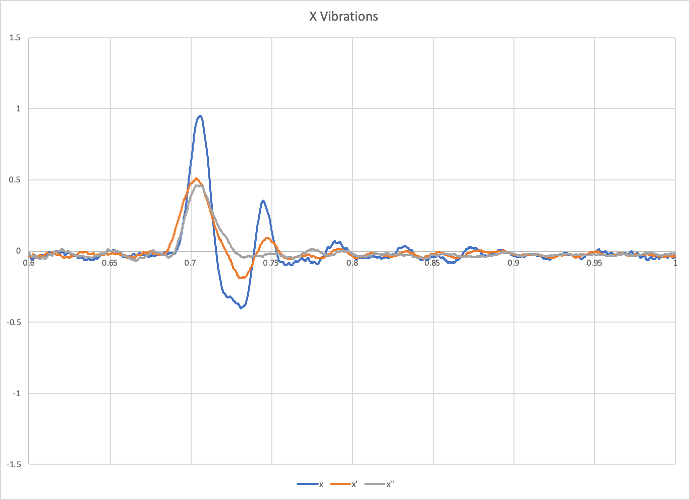
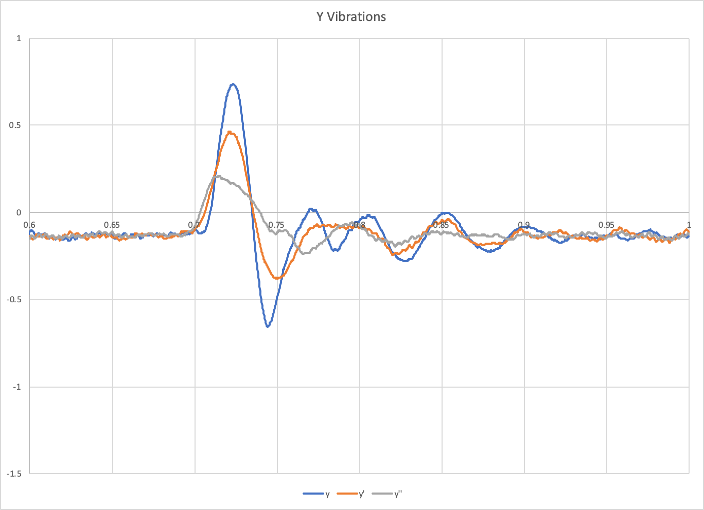
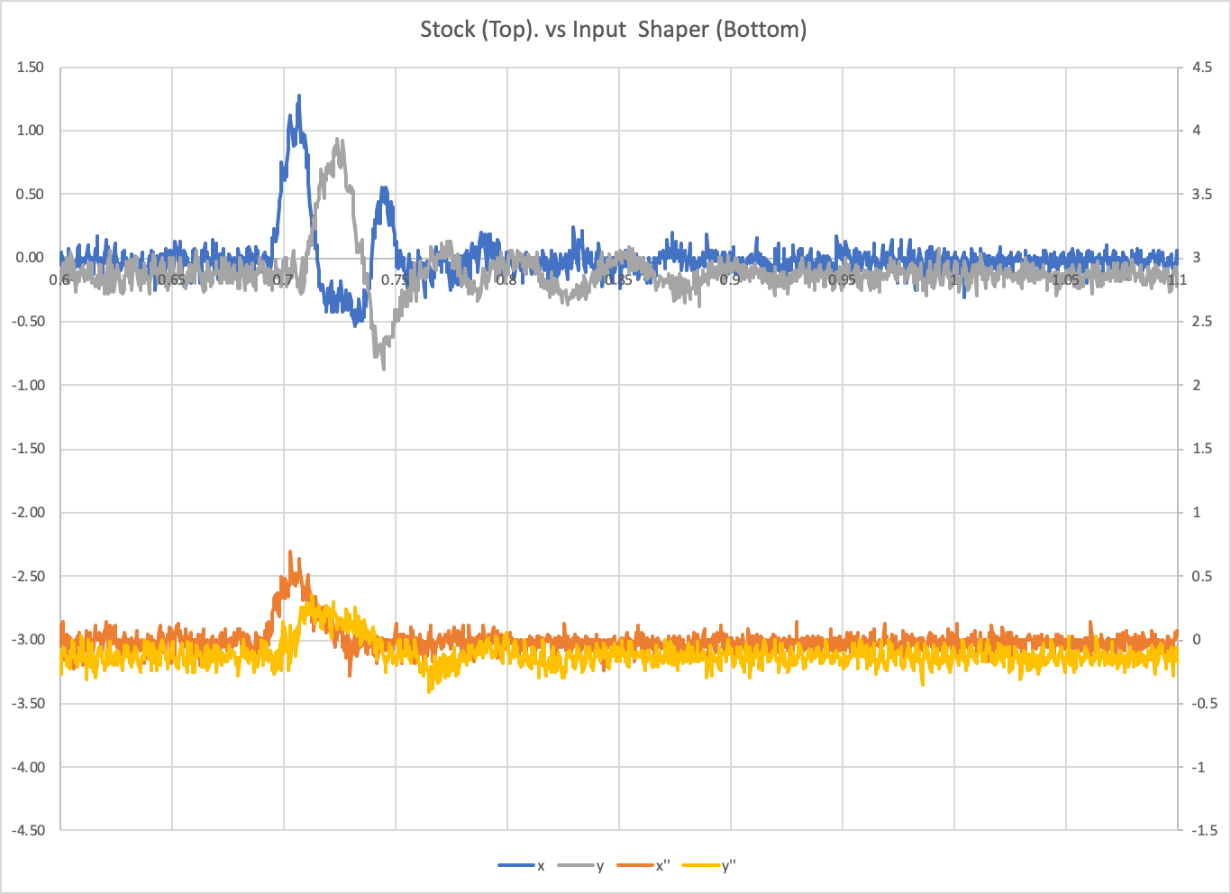
On the main Pi driving the printer, I set up a macro to run the toolhead in a square tool path, 50mm/s, at 100mm/s. I started that macro, and then immediately started a 2 second 3200Hz scan of the accelerometer on the second Pi. This allowed me to measure the accelerometer output at the same time the toolhead was moving.
I did 3 runs, one without input shaping, one with input shaping at x=37Hz and y=36Hz, and one with input shaping at x=31Hz and y=20Hz. Here are plots of X, Y, and Z. x, x`, and x`` are these three tests respectively.
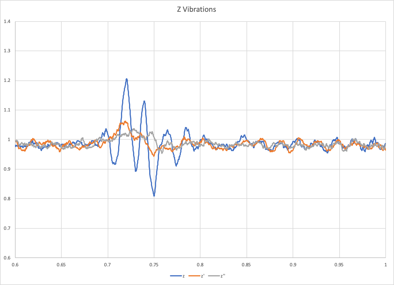
And finally, a plot of X and Y resonance together:
If we could tie tool path/target positioning with accelerometer data, could we create a displacement model to overlay target/actual tool paths and show ringing reduction that way?
jdlongenecker
on 31 Jul 2020
@KevinOConnor Thanks, that's really promising as a proof-of-concept! I think the resonance testing code can use some generic interface to ADXL345 class.
I was seeing about 10% cpu usage for both klippy and the linux mcu.
Interesting. I've tried to implement FIFO (1d53115978a2347154e6bd48d55a28769c6a0b00). I think it works OK (but I need to do more tests to be sure). However, I did not observe a significant reduction in cpu taken by pigpiod (~35%) and Klipper (~25%). Maybe I did something wrong though.
For your code I only had a minor comment that, according to the specs, it is necessary to have 5 usec delay between FIFO read and the next read or querying FIFO_STATUS register. At 5 MHz SPI speed there is insufficient delay between the read of the last Z register and reading FIFO_STATUS register now (reading FIFO_CTL register only: 8 bits / 5000000 = 1.6 usec).
dmbutyugin
on 31 Jul 2020
@jdlongenecker My thinking is that we can make the toolhead go over a segment (line) back and forth and have it make a velocity jump at the ends of the segment. Then we can check the vibrations with and without the input shaper. But mapping measured (and noisy) acceleration data to a toolpath might be a bit more problematic.
dmbutyugin
on 31 Jul 2020
makes sense, I was looking at some info that essentially said even a small error in the accelerometer values stacks up significantly once it turns into velocity and displacement--probably a bit too much to ask of an inexpensive sensor and imperfect mounting 👍
It would be cool if theoretically you could mount the accelerometer, and then run a script/macro that essentially iteratively auto tunes the settings to optimize the response.
jdlongenecker
on 31 Jul 2020
@jdlongenecker
It would be cool if theoretically you could mount the accelerometer, and then run a script/macro that essentially iteratively auto tunes the settings to optimize the response.
That would be great, of course. But it may take a while before we get there :) Though we may be able to automate the resonance detection and tuning, with less human intervention required.
dmbutyugin
on 31 Jul 2020
For your code I only had a minor comment that, according to the specs, it is necessary to have 5 usec delay between FIFO read and the next read or querying FIFO_STATUS register.
Thanks for reviewing. I did see that in the spec, but the wording is actually, To ensure that the FIFO has completely popped (that
is, that new data has completely moved into the DATAX, DATAY,
and DATAZ registers), there must be at least 5 µs between the
end of reading the data registers and the start of a new read of
the FIFO or a read of the FIFO_STATUS register (Address 0x39). I take that to mean it is okay to read FIFO_STATUS in a burst, but it may reflect the past state or (depending on timing) the new state. That's why the code checks for "fifo_entries > 1" before querying again, as a 1 may be the data just read. But anything more than 1 should indicate there's data buffered.
That said, I still need to verify the data.
However, I did not observe a significant reduction in cpu taken by pigpiod (~35%) and Klipper (~25%).
That might be overhead in pigpiod.
@jdlongenecker
If we could tie tool path/target positioning with accelerometer data, could we create a displacement model to overlay target/actual tool paths and show ringing reduction that way?
It should be possible to align the accelerometer responses with the internal "velocity trapezoid queue", but that would be a lot of work. So, it's possible, but probably not a short term project.
-Kevin
KevinOConnor
on 31 Jul 2020
FYI, I was able to make some further enhancements and run further tests on the work-adxl345-2020730 branch.
The config and commands work as before ( https://github.com/KevinOConnor/klipper/issues/3027#issuecomment-666742653 ). However, now the data is written to a file named like /tmp/adxl345-YYYYMMDD_HHMMSS.csv. I also put together a graphing script (requires matplotlib): ./scripts/graph_adxl345.py adxl345-YYYYMMDD_HHMMSS.csv.
It looks like the query code is stable - I added more diagnostics to try to catch lost or corrupted data and I haven't seen any indication of a problem. I'm getting a very reliable sample rate of .000319s per sample (which isn't quite 3200sps, but I'm guessing the difference is just due to clock drift).
Here's a graph of a homing operation on the M2:
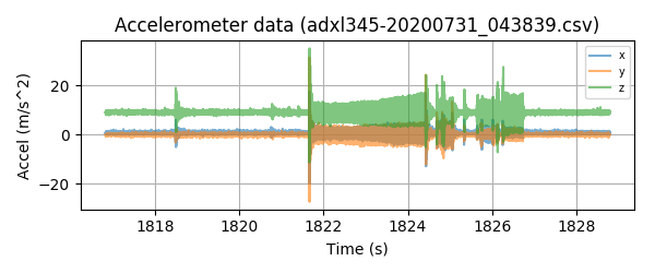
This is with the sensor on the bed, so the X movement isn't very noticeable. However, the Y and Z homing can be clearly seen. I'm not sure if this sensor is just noisy, or if the bed really does vibrate that much even during constant velocity.
If anyone else wants to try:
cd ~/klipper ; git fetch ; git checkout origin/work-adxl345-20200730 ; sudo service klipper stop ; make flash ; sudo service klipper start
The acceleration data is currently stored in memory, so don't run measurements for more than a minute or so at a time.
-Kevin
KevinOConnor
on 31 Jul 2020
I took a look at the "noise" during the constant speed Y homing moves. It appears to be a ~275hz signal - which matches the full step rate for the Y axis during homing. Similarly, during the Z second home phase there is a ~500hz signal - which matches the Z leadscrew micro-step homing rate.
So, interestingly, it appears the accelerometer is able to pick up the "noise" from the stepper motors steps.
-Kevin
KevinOConnor
on 31 Jul 2020
Hello everyone,
I've been watching this conversation for a while and was able to hook up an ADXL345 to my modded (direct drive) Ender 3 Pro. The resonances I measured seem pretty clear to me (about the same in both axis, 38.6Hz in Y and 39.2Hz in X at peak). What's lost on me is understanding which Shaping algorithm I should use (MZV vs EI etc)
Any advice or clarification would be helpful.
 pengsloth
on 31 Jul 2020
pengsloth
on 31 Jul 2020
@pengsloth Well, the accelerometer only helps you find the resonances. Sine you only have 1 strong resonance per axis, you can just use these results in lieu of this print. To choose the shaper, refer to the corresponding section of the documentation - you will still need to print the test model a couple of times. In general, a quote from there: "EI shaper may be more suited for bed slinger printers (if the resonance frequency and resulting smoothing allows)"
dmbutyugin
on 31 Jul 2020
@KevinOConnor
That's why the code checks for "fifo_entries > 1" before querying again, as a 1 may be the data just read.
Ah OK, then it was simply my confusion.
That might be overhead in pigpiod.
Yes, very possible.
I'm getting a very reliable sample rate of .000319s per sample (which isn't quite 3200sps, but I'm guessing the difference is just due to clock drift).
So the difference is within +/- 2%. It is probably due to small inaccuracy of the internal clocks (most probably the one on ADXL345). I do not think it will affect the quality of the resonance detection (within that accuracy range, naturally). It might be easier just to assume the stable rate of exactly 3200 Hz.
FWIW, I tried your branch and got the basic measurements successfully. Though in my case I am getting consistently time_per_sample=0.000324. Which is almost 4% error.
I took a look at the "noise" during the constant speed Y homing moves. It appears to be a ~275hz signal - which matches the full step rate for the Y axis during homing. Similarly, during the Z second home phase there is a ~500hz signal - which matches the Z leadscrew micro-step homing rate.
So, interestingly, it appears the accelerometer is able to pick up the "noise" from the stepper motors steps.
Yes, indeed! I noticed that kind of signal during my tests too - though I was not sure if this a noise from the steppers (most likely), pulleys, or even linear guide rails (balls inside the carriage). And on a delta the signal has much less stable frequency. BTW, it does not appear to affect the ability of the code to measure the response (and find resonances), which is good.
In general, I would propose to test the reliability more and then integrate your ADXL345 code into the mainline. I will change resonance_tester.py code to use adxl345.py (with some nicer API) then. Afterwards, we can try adjusting the testing procedure, since we'll have more freedom of what kind of tests we can schedule and measure. I think we anyways agreed that the code to handle accelerometer reads should be something like what you have implemented. Or I can try doing that on top of your branch - but for the next couple of weeks I'll be away from my printer, so I won't be able to run the tests 'in hardware' myself.
dmbutyugin
on 31 Jul 2020
It might be easier just to assume the stable rate of exactly 3200 Hz.
It's easy to measure the actual rate (total_time / total_samples), so doesn't hurt to use more precise timing. I agree it's unlikely to impact the resonance testing though.
FYI, I made some additional tweaks on the work-adxl345-20200730 branch to further improve the calculation of "total_time". It should now be able to calculate that to within about 100us.
Though in my case I am getting consistently time_per_sample=0.000324. Which is almost 4% error.
Interesting. Did the final csv file show limit_count=0 and (at the end of the file) drops=0? If you didn't get any drops and there was no indication of an overrun then I'd say it's most likely the adxl345 clock running a little slow. If it consistently runs slow (that is, if several tests all show .000324) then it shouldn't be a problem.
In general, I would propose to test the reliability more and then integrate your ADXL345 code into the mainline. I will change resonance_tester.py code to use adxl345.py (with some nicer API) then.
Okay, thanks. I'll clean up the code and open a PR for work-adxl345-20200730. Key to this support will be the resonance testing feature. We can merge that when you're ready though.
-Kevin
KevinOConnor
on 31 Jul 2020
It's easy to measure the actual rate (
total_time / total_samples), so doesn't hurt to use more precise timing. I agree it's unlikely to impact the resonance testing though.
TBH, 4% error may already impact ZV and even MZV shaper tuning (though less for MZV). So, as long as we are confident about the measurements (I can imagine that the total_time may be computed with an error of ~2 / 3200 sec, so cumulatively the error should be small), then it's probably better to get as accurate measurement rate as possible.
Though in my case I am getting consistently time_per_sample=0.000324. Which is almost 4% error.
Interesting. Did the final csv file show
limit_count=0and (at the end of the file)drops=0? If you didn't get any drops and there was no indication of an overrun then I'd say it's most likely the adxl345 clock running a little slow. If it consistently runs slow (that is, if several tests all show .000324) then it shouldn't be a problem.
Yes, it was really consistent. The latest attempt:
##start=35.848551/35.848652,end=59.308862/59.308891
##limit_count=0,end_seq=9065,time_per_sample=0.000323527
#time,x,y,z
35.848652,0.627626,-0.156906,9.885103
35.848976,0.078453,0.706079,9.414384
...
59.308244,0.313813,0.627626,9.257478
59.308568,0.235360,0.470719,9.728197
##count=72514/72514,drops=0
In general, I would propose to test the reliability more and then integrate your ADXL345 code into the mainline. I will change resonance_tester.py code to use adxl345.py (with some nicer API) then.
Okay, thanks. I'll clean up the code and open a PR for work-adxl345-20200730. Key to this support will be the resonance testing feature. We can merge that when you're ready though.
OK, sounds good. Agreed that it's only useful with the resonance testing.
dmbutyugin
on 1 Aug 2020
@KevinOConnor it would be helpful if you could define your accelerometer orientation relative to your printer axes, like:
axis_alignment: zyx
if your z and x axes are swapped, or
axis_alignment: xyz
if they match the accelerometer. Then the data output would be correct without post processing.
I'll share my before/after data tomorrow here--I took a baseline before swapping from Dmitri's branch and am redoing the same data points to make sure everything looks good!
Thanks
jdlongenecker
on 10 Aug 2020
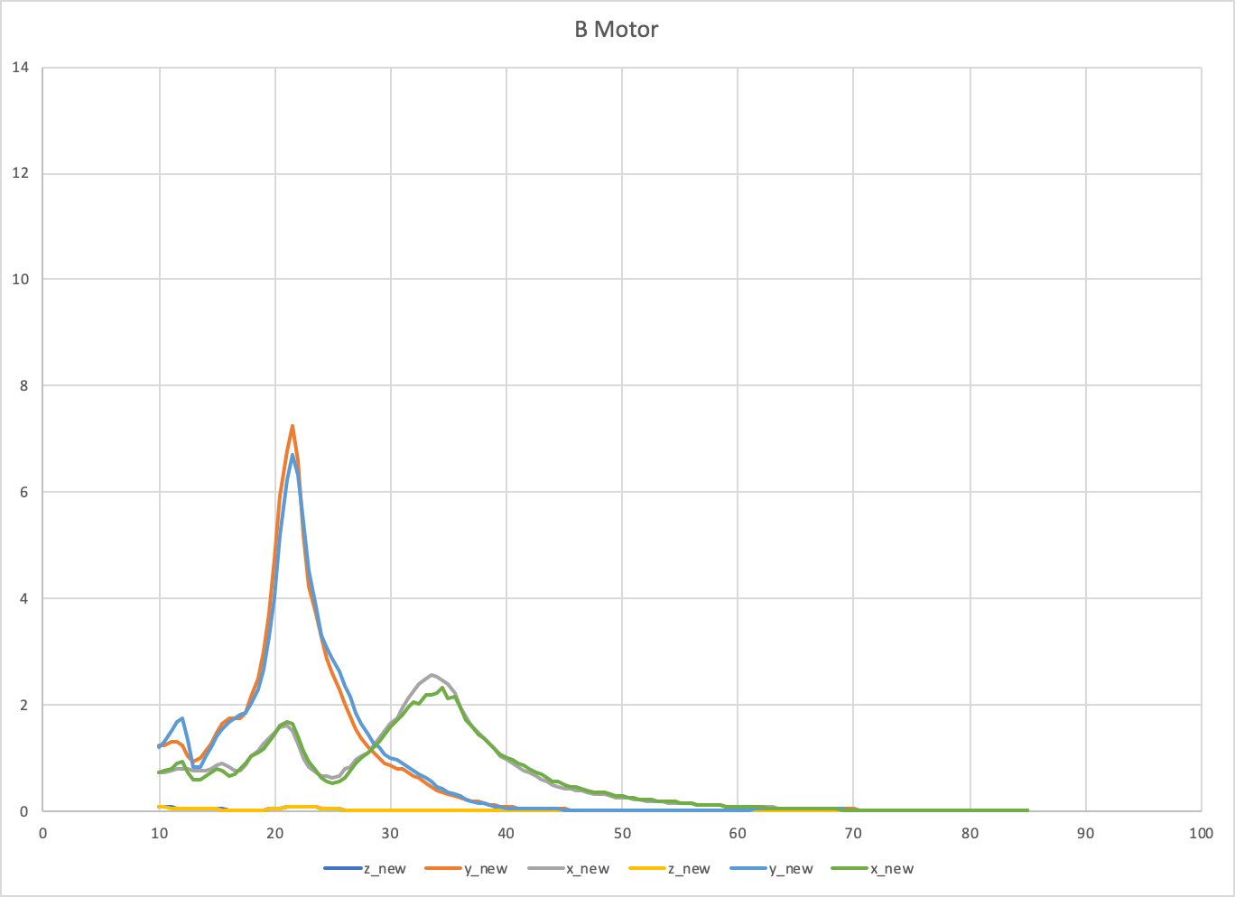
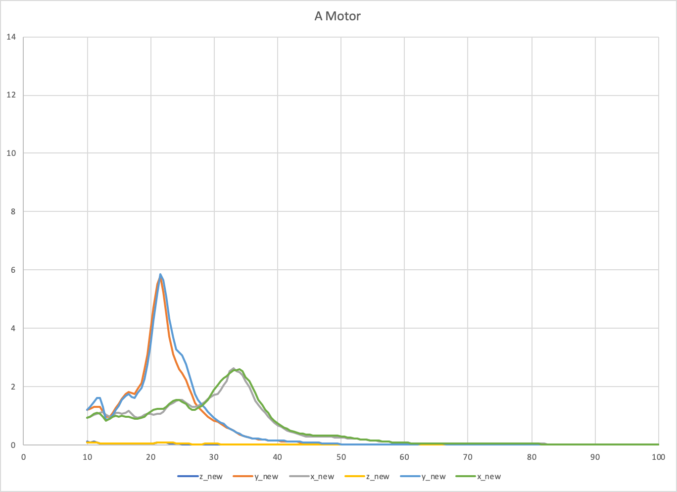
@KevinOConnor here's before (Dmitri's fork) and after (this pull request) data for X, Y, A, and B on a CoreXY printer. I believe this is well within the standard run to run variance!
jdlongenecker
on 11 Aug 2020
I've created two basic macros for testing data on my printer, including one that measures vibrations when the toolhead has stopped. Raw data, basic instructions, and macros can be found here:
https://github.com/jdlongenecker/documentation/tree/master/vibration_data
Results with/without input shaper:
jdlongenecker
on 11 Aug 2020
@KevinOConnor I ran some tests with your branch work-adxl345-20200730 and it seems to work fine. I think it makes sense to target that ADXL345 code, and do some cleanups of the resonance_tester.py. One big advantage of adxl345 support from your branch is that now the host code can handle long sequences of moves, not just a few seconds. This gives an opportunity to run the test for a few minutes and still get all readings without the gaps between the movements.
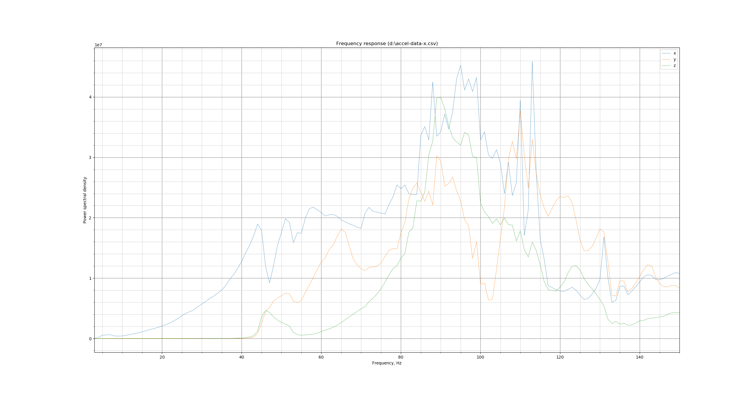
Separately, I started some experiments with slightly different resonance tests. For one, I updated TEST_RESONANCES to work properly. Note that it requires some post-processing with FFT now, but the measurement process is, perhaps, more robust. If some of you folks could give it a try, you can check out this branch, configure it as appropriate, and run the test
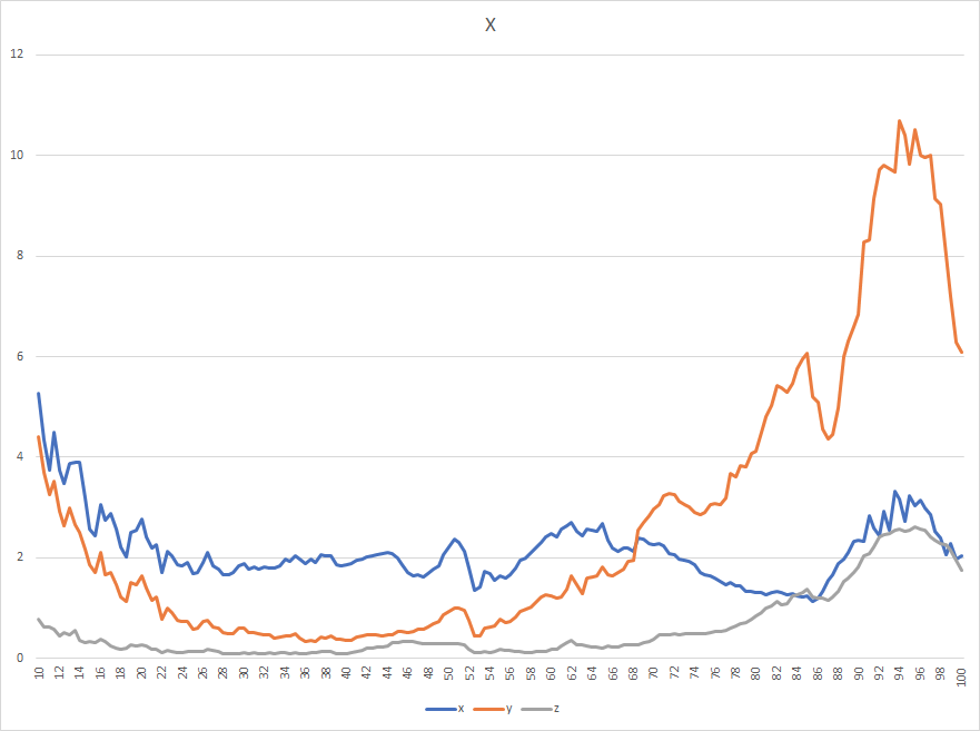
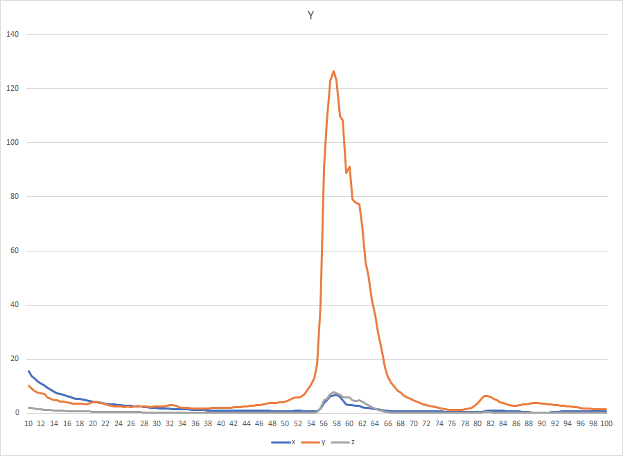
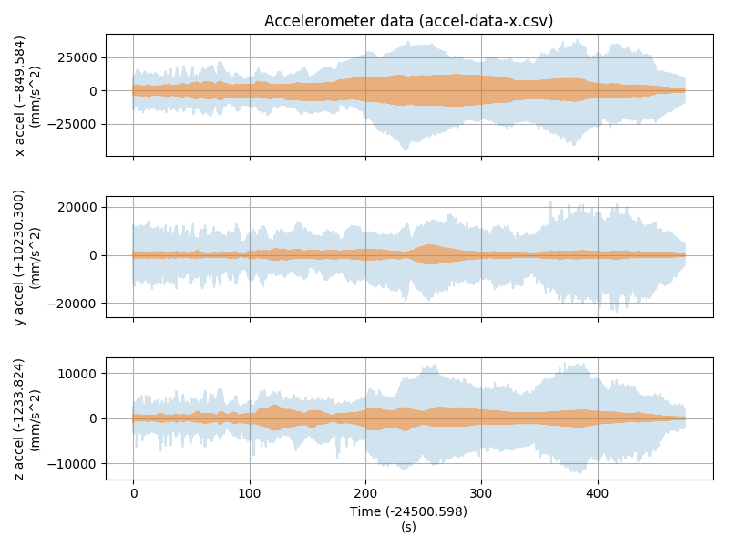
TEST_RESONANCES X=100 Y=100 Z=20 AXIS=X RAW_OUTPUT=/tmp/accel-data-x.csv
(X, Y and Z values are just examples here). Then download the file /tmp/accel-data-x.csv, and run the following script, e.g.
$ python scripts/specgram.py accel-data-x.csv
It can plot a chart like this
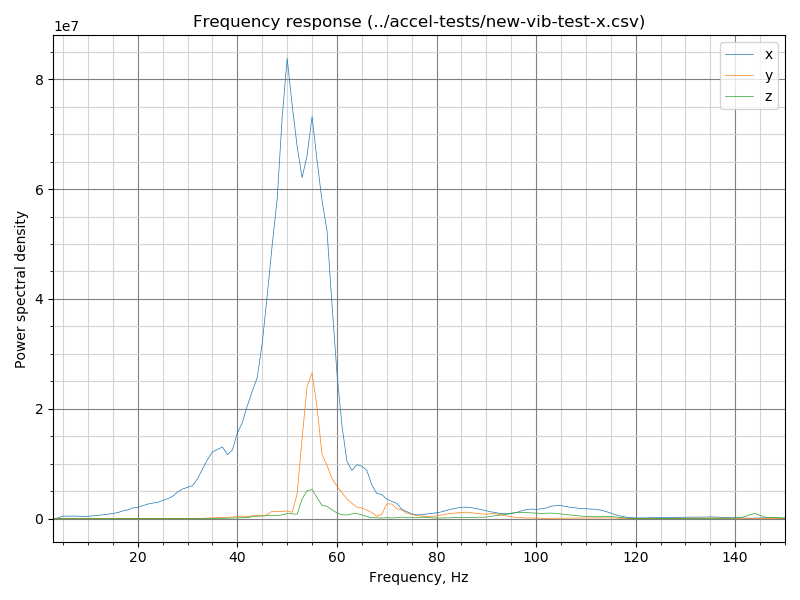
The results of the measurements are very comparable to the old method, but I think it works better for low frequencies:
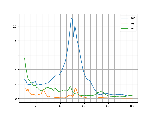
If this new test works well for others, I want to see if further advancements are possible.
dmbutyugin
on 30 Aug 2020
Hello @dmbutyugin!
I was able to test this tonight!
Basic feedback for someone not super savvy:
-Was able to switch to your branch without changing anything other than checking it out. Nice and easy (had been on the respective klipper branch before)
-Test ran much faster than the previous version which is a welcome change!
-After it reached 100Hz, it said the following and I wasn't sure if it was still working or not (it was, just took a bit to process I guess--I didn't realize the file would be so large!
Recv: // Testing frequency 97 Hz
Recv: // Testing frequency 98 Hz
Recv: // Testing frequency 99 Hz
Recv: // Testing frequency 100 Hz
Communication timeout while idle, trying to trigger response from printer. Configure long running commands or increase communication timeout if that happens regularly on specific commands or long moves.
Send: M105
Recv: // ADXL345 stats: drops=0,overflows=0,time_per_sample=0.000304702,start_range=0.000041,end_range=0.000048
Recv: ok
Send: M105
Recv: ok B:0.0 /0.0 C:22.9 /0.0 T0:0.0 /0.0
When trying to run the python script as you mentioned (after changing accel-data-x.csv tot /tmp/accel-data-x.csv), I get the following error:
pi@miniV:~/klipper $ python scripts/specgram.py accel-data-x.csv
Traceback (most recent call last):
  File "scripts/specgram.py", line 98, in <module>
    main()
  File "scripts/specgram.py", line 88, in main
    fig = plot_accel(data, args[0])
  File "scripts/specgram.py", line 56, in plot_accel
    fig, ax = plt.subplots()
  File "/usr/lib/python2.7/dist-packages/matplotlib/pyplot.py", line 1203, in subplots
    fig = figure(**fig_kw)
  File "/usr/lib/python2.7/dist-packages/matplotlib/pyplot.py", line 535, in figure
    **kwargs)
  File "/usr/lib/python2.7/dist-packages/matplotlib/backends/backend_tkagg.py", line 81, in new_figure_manager
    return new_figure_manager_given_figure(num, figure)
  File "/usr/lib/python2.7/dist-packages/matplotlib/backends/backend_tkagg.py", line 89, in new_figure_manager_given_figure
    window = Tk.Tk()
  File "/usr/lib/python2.7/lib-tk/Tkinter.py", line 1823, in __init__
    self.tk = _tkinter.create(screenName, baseName, className, interactive, wantobjects, useTk, sync, use)
_tkinter.TclError: no display name and no $DISPLAY environment variable
Both of these may be trivial to fix and I may be missing something obvious :) but I figured I'd give my experience regardless.
I've attached 4 tests in a Zip folder. X and Y with TEST_RESONANCES, and X and Y with TEST_VIBRATIONS.
Archive.zip
jdlongenecker
on 30 Aug 2020
I thought I give it a run as well.
@jdlongenecker
The error you are getting is due to running the script (via SSH?) on the PI. The script tries to open an interactive Xwindows, which will fail on this device. Try running on Windows or Linux with a desktop environment.
Results:
"Traditional" Way X
FFT X

"Traditional" Way Y
FFT Y
Data Package:
https://drive.google.com/file/d/1N8_UODsMVXwOLGF0KUM51u8ySJBq4B5J/view?usp=sharing
Sineos
on 30 Aug 2020
Hi, thanks! FWIW, the results do seem very comparable between both tests, but the new test does not emphasize the vibrations at the low end of the spectrum. That, I think, is happening because low-frequency vibrations can excite higher-frequency vibrations due to small non-linear effects, but the old test just captures the increased amplitude, and the new test attributes these vibrations to the correct higher frequency oscillations.
Indeed, the new test runs much faster. But the raw output is much larger now than before (a few tens of MB), because it actually contains all the accelerometer readings during the test. As a side effect, it takes a bit at the end to write the file down to SD card, but no need to worry - it only takes a few dozens of seconds.
@jdlongenecker
When trying to run the python script as you mentioned (after changing accel-data-x.csv tot /tmp/accel-data-x.csv), I get the following error:
Yes, that script should be executed on your desktop/laptop. Alternatively, you could run it as
$ python ~/klipper/scripts/specgram.py /tmp/accel-data-x.csv -o plot-x.png
which will write plot-x.png that can be downloaded from Raspberry Pi.
@Sineos I see that your results on X axis abruptly end at ~100 Hz, which is the end of the test as well. Could you run the test also with the higher end frequency (also updating to the latest code from the branch)?
TEST_RESONANCES X=100 Y=100 Z=20 AXIS=X FREQ_END=150 RAW_OUTPUT=/tmp/accel-data-x.csv
I actually do not expect your results to change, but just want to double-check.
Separately, your X test shows more cross-axes excitation near the resonance in FFT test than in the 'traditional' test. I wonder why is that.
dmbutyugin
on 30 Aug 2020
@dmbutyugin
As requested - for my eyes they look quite different, especially on the "untested" axes
X up to 150 "traditional":
X up to 150 "FFT":
Data Package
https://drive.google.com/file/d/1wRSfALPGsy2j6IF91-72MNPE-n57W2BN/view?usp=sharing
It would be helpful when the FFT script also outputs a csv with the processed values since analysis with a spreadsheet tool like Excel or similar is easier than only the graphical approach of the python engine.
Sineos
on 30 Aug 2020
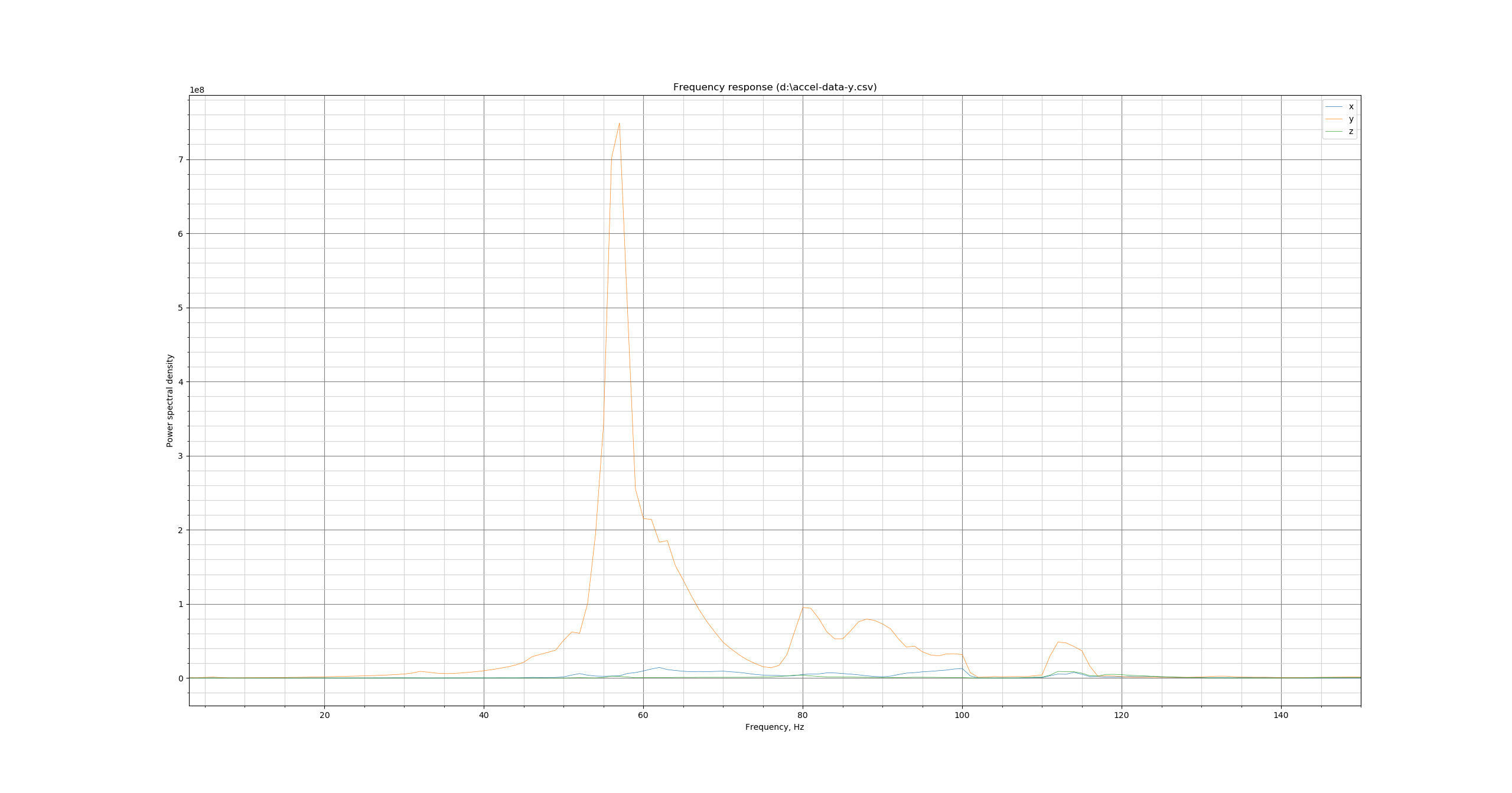
@dmbutyugin - FYI, I ran a test with TEST_RESONANCES (just for Y and just with accelerometer on the corner of the bed):
set_input_shaper shaper_freq_x=0 shaper_freq_y=0
set_velocity_limit accel=2000
g28
g1 x100 y100 z20 f600
set_velocity_limit accel=7000
TEST_VIBRATIONS X=100 Y=100 Z=20 AXIS=Y FREQ_START=10 FREQ_END=100 FREQ_STEP=0.5 OUTPUT=/tmp/vib-y.csv
TEST_RESONANCES X=100 Y=100 Z=20 AXIS=Y RAW_OUTPUT=/tmp/accel-data-y.csv
I'm not sure this printer is a good test case, but old and new do seem to show a lot of overlap.
Old:
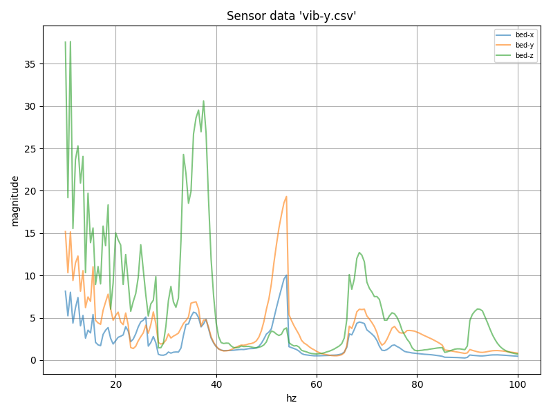
New:
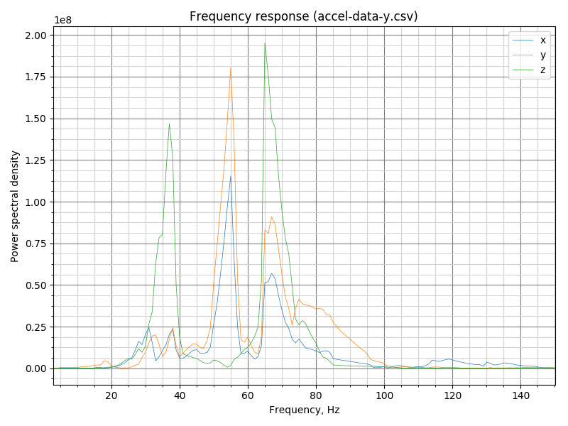
New test, raw data graph:
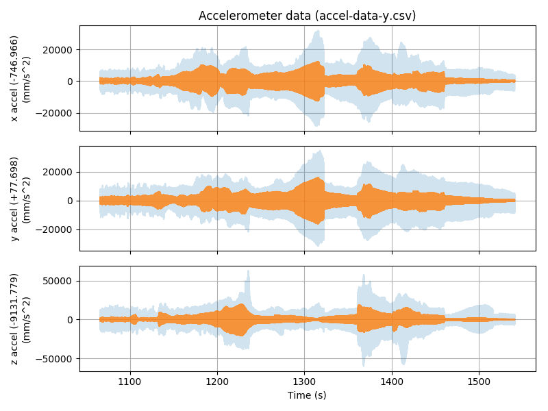
-Kevin
KevinOConnor
on 31 Aug 2020
@KevinOConnor Thanks! Would you mind archiving and sharing the raw file with accel data? I am testing some autocalibration code now, and I think your case is quite interesting.
dmbutyugin
on 1 Sep 2020
@dmbutyugin - I'm not sure this printer is a good test case, but feel free to take a look:
accel-data-y.csv.gz
vib-y.csv.gz
klippy.log.2020-08-31.gz
-Kevin
KevinOConnor
on 1 Sep 2020
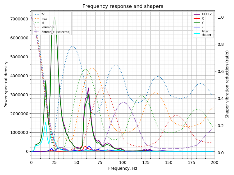
Well, in this case the autocalibration code recommends 3hump_ei shaper at 58.3 Hz for Y axis:
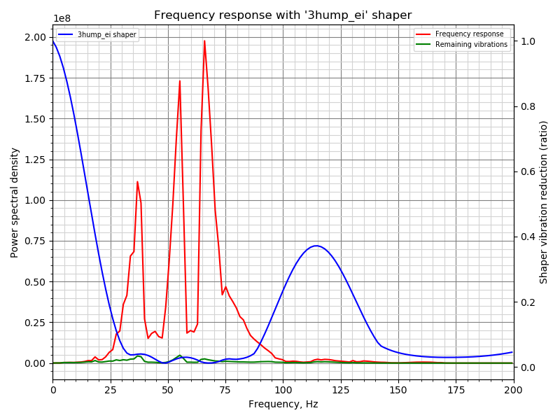
dmbutyugin
on 1 Sep 2020
FWIW, this is how other fitted shapers look like in this case:
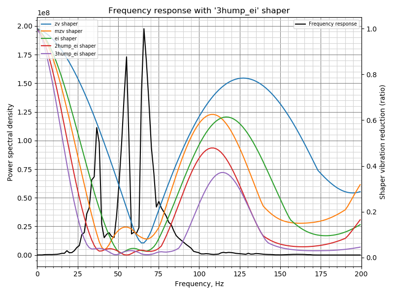
Fitted shaper 'zv' frequency = 65.2 Hz
Fitted shaper 'mzv' frequency = 41.4 Hz
Fitted shaper 'ei' frequency = 59.8 Hz
Fitted shaper '2hump_ei' frequency = 55.2 Hz
Fitted shaper '3hump_ei' frequency = 58.3 Hz
dmbutyugin
on 1 Sep 2020
That's really useful! Any suggestions on a good way to test those values? Visually, it does look like 2hump_ei is pretty good as well.
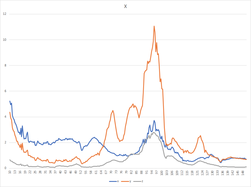
FYI, I moved the wires to the accelerometer on the toolhead and tested X with that.
Old (axes are correct):
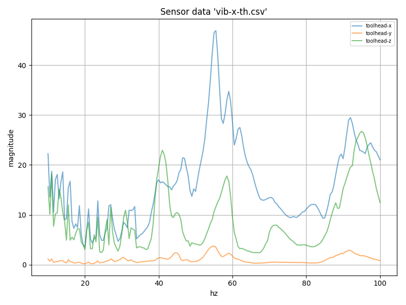
New (y and z are swapped):
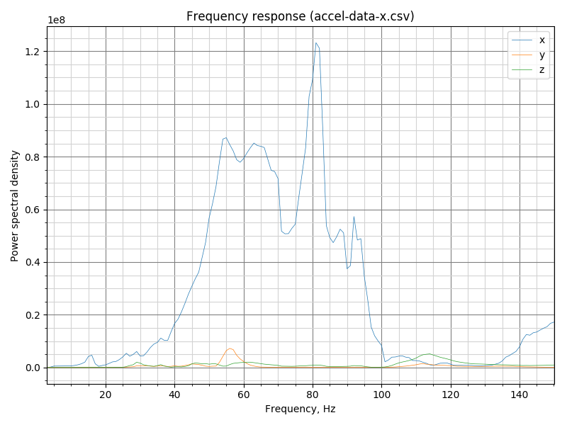
New (raw; y and z are swapped):
Interesting that this does differ a bit from the old method.
klippy.log.gz
vib-x-th.csv.gz
accel-data-x.csv.gz
-Kevin
KevinOConnor
on 1 Sep 2020
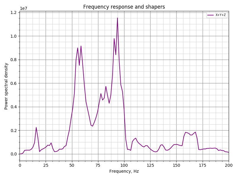
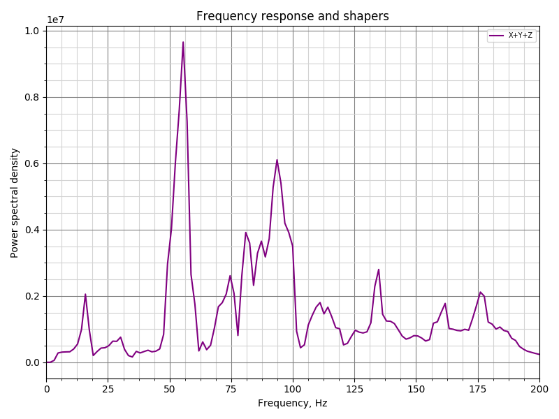
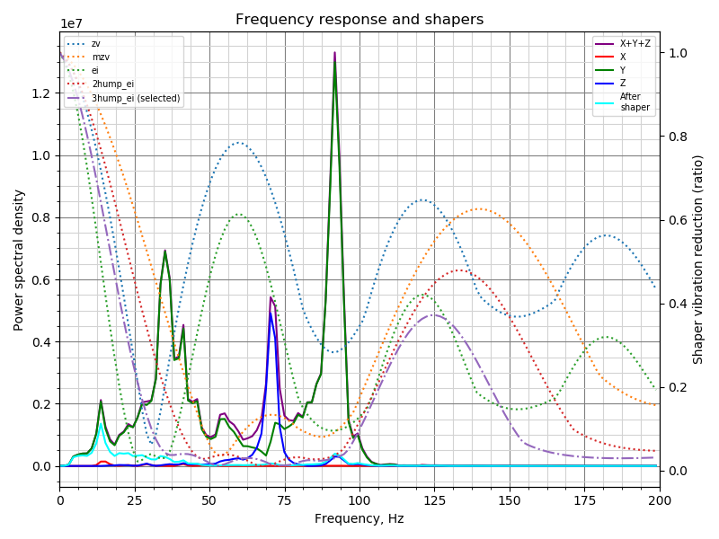
OK, so I pushed the automatic shaper calibration code to my test branch. @KevinOConnor I slightly reworked the logic to compare different input shaper, and now for your Y axis data it picks 2hump_ei shaper. For X axis the results are as follows:
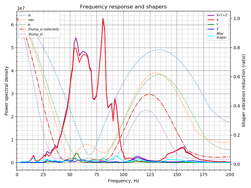
Fitted shaper 'zv' frequency = 68.2 Hz (vibrations = 30.6%)
Fitted shaper 'mzv' frequency = 49.9 Hz (vibrations = 13.8%)
Fitted shaper 'ei' frequency = 68.2 Hz (vibrations = 12.2%)
Fitted shaper '2hump_ei' frequency = 63.4 Hz (vibrations = 6.2%)
Fitted shaper '3hump_ei' frequency = 61.8 Hz (vibrations = 3.9%)
Recommended shaper is 2hump_ei @ 63.4 Hz
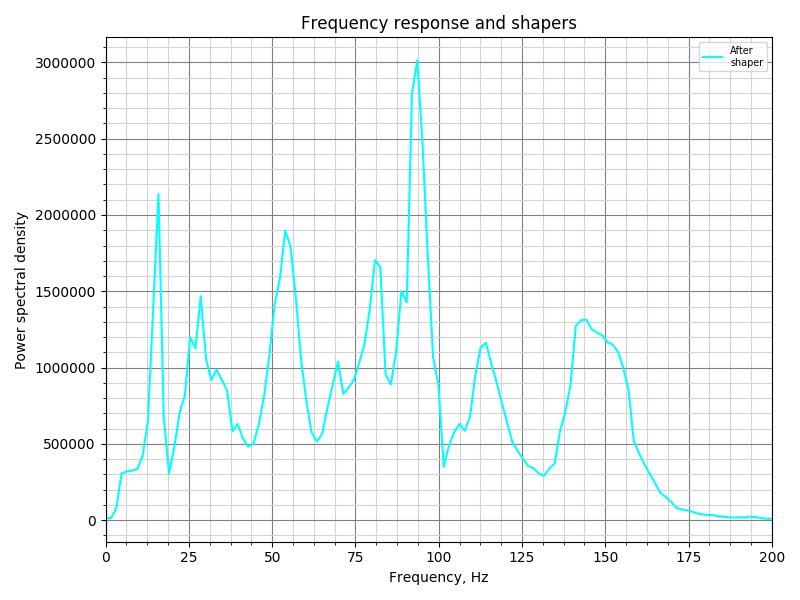
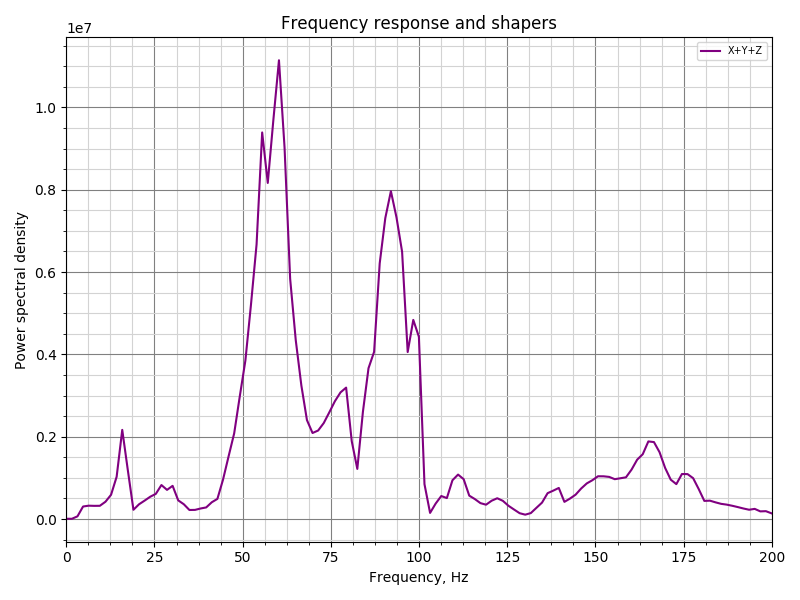
BTW, I updated the chart format, let me know what you think. It has more technical details now, but maybe it is too 'loaded' now and harder to read.
There are 2 ways to try the new shaper tuning algorithm. First, if the raw data is generated using the command like
TEST_RESONANCES X=100 Y=100 Z=20 AXIS=X RAW_OUTPUT=/tmp/accel-data-x.csv
then one can run the following command on their Pi:
$ ~/klippy-env/bin/python ~/klipper/klippy/extras/shaper_calibrate.py /tmp/accel-data-x.csv -o /tmp/shaper_calibration_x.png
and it will print the output like above for the shapers, as well as will generate the png with the graphical results.
There's one even better way now. One can run the command in Octoprint
SHAPER_CALIBRATE PROBE_POINTS=100,100,20 AXES=XY RAW_OUTPUT=/tmp/accel-data.csv FIG_BASENAME=/tmp/shaper_calibration.png
Parameters RAW_OUTPUT and FIG_BASENAME are, in principle, optional, but if you try this, please generate these outputs for now too (they are useful for debugging and such). AXES=XY is a default and can be omitted too (so it makes sense to set AXES=X or AXES=Y in case of a separate testing). PROBE_POINTS can accept multiple points, e.g. if you want to test a few points on the buildplate, you can set, for instance, PROBE_POINTS=100,100,20:50,100,20:-50,100,20:100,50,20:100,-50,20, and the SHAPER_CALIBRATE will measure the vibration responses at all these points and use them in the calculations. After completion, it will print the tested and suggested parameters for the shaper, and you can execute SAVE_CONFIG to save the parameters if you are satisfied with the automatic choice. In case of a bed slinger printer the sensor must be mounted in different locations for X and Y axes tests, so for now one has to run the test twice for X and Y axes separately, re-mounting or reconnecting the adxl345 sensor in the meanwhile.
Note that shaper autocalibration requires additional dependencies not installed by default. You will have to run on your Raspberry Pi
$ ~/klippy-env/bin/pip install matplotlib
first time prior to running either of the methods.
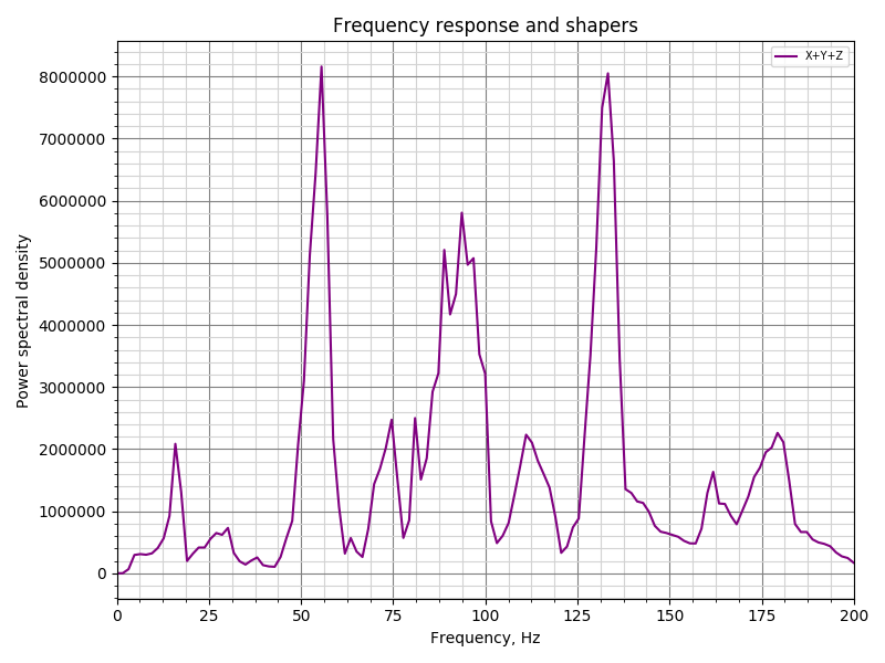
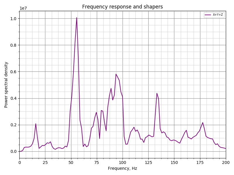
Some other interesting calibration results:
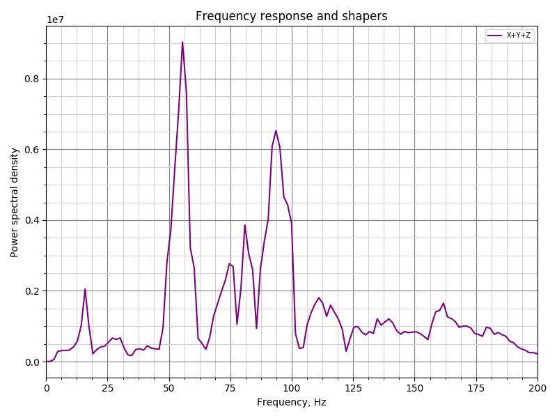
@jdlongenecker from your Y axis data, suggested is 3hump_ei @ 51.2 Hz (and 2hump_ei @ 38.4 Hz for X axis):
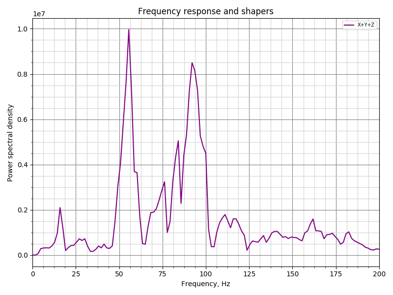
@Sineos from your X axis data, suggested is 2hump_ei @ 95.4 Hz (and 2hump_ei @ 78.7 Hz for Y axis):
Now, how to test the tuned parameters? I don't know :) But I suppose it would be better experimentally, to simply try and print the resonance test and see if there is still some ringing left.
As a side note, I do not claim that the calibration code does physically sound calculations for each of the input shapers, but at least it appears to be picking good frequencies for each shaper. The algorithm can be rough around the edges for now, and also may not produce exactly repeatable results run-to-run: for different runs the measured data can be somewhat different, and this may make the tuning algorithm pick slightly different parameters (and even different shapers). Hopefully the ringing suppression should not change too much from calibration to calibration. But this is one of the reasons I wouldn't recommend one to make this tuning test an everyday procedure.
dmbutyugin
on 2 Sep 2020
Now, how to test the tuned parameters? I don't know :) But I suppose it would be better experimentally, to simply try and print the resonance test and see if there is still some ringing left.
Just for kicks, I reran TEST_RESONANCES after setting an input shaper:
  set_input_shaper shaper_freq_x=63.4
  set_velocity_limit accel=2000
  g28
  g1 x100 y100 z20 f600
  set_velocity_limit accel=7000
  TEST_RESONANCES X=100 Y=100 Z=20 AXIS=X RAW_OUTPUT=/tmp/accel-data-x2.csv
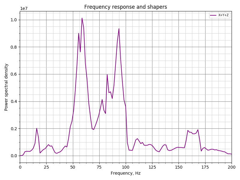
What I thought was interesting is that the predictions for remaining vibrations was actually quite good.
Predicted with 2hump_ei/63.4:
Measured with 2hump_ei/63.4:
The actual magnitude for the remaining frequencies between 50-100hz is about 4x the prediction, but the peaks do line up. (And, it's still a ~10x total reduction in magnitude.)
-Kevin
KevinOConnor
on 2 Sep 2020
Hey @dmbutyugin:
Running TEST_RESONANCES standalone works fine and I get the automatic calibration data. However, when running it from OctoPrint by running SHAPER_CALIBRATE PROBE_POINTS=100,100,20 AXES=XY RAW_OUTPUT=/tmp/accel-data.csv FIG_BASENAME=/tmp/shaper_calibration.png I get an error:
stepcompress o=6 i=0 c=74 a=0: Invalid sequence
stepcompress o=6 i=0 c=74 a=0: Invalid sequence
Internal error on command:"SHAPER_CALIBRATE"
Traceback (most recent call last):
  File "/home/pi/src/klipper/klippy/gcode.py", line 177, in _process_commands
    handler(gcmd)
  File "/home/pi/src/klipper/klippy/gcode.py", line 115, in <lambda>
    func = lambda params: origfunc(self._get_extended_params(params))
  File "/home/pi/src/klipper/klippy/extras/resonance_tester.py", line 240, in cmd_SHAPER_CALIBRATE
    freq_end, hz_per_sec, gcmd)
  File "/home/pi/src/klipper/klippy/extras/resonance_tester.py", line 370, in _run_test2
    toolhead.move([nX, nY, Z, E], V)
  File "/home/pi/src/klipper/klippy/toolhead.py", line 415, in move
    self.move_queue.add_move(move)
  File "/home/pi/src/klipper/klippy/toolhead.py", line 182, in add_move
    self.flush(lazy=True)
  File "/home/pi/src/klipper/klippy/toolhead.py", line 171, in flush
    self.toolhead._process_moves(queue[:flush_count])
  File "/home/pi/src/klipper/klippy/toolhead.py", line 331, in _process_moves
    self._update_move_time(next_move_time)
  File "/home/pi/src/klipper/klippy/toolhead.py", line 284, in _update_move_time
    sg(sg_flush_time)
  File "/home/pi/src/klipper/klippy/stepper.py", line 171, in generate_steps
    raise error("Internal error in stepcompress")
error: Internal error in stepcompress
Attaching klippy.log for your reference.
klippy.log
 agsolino
on 2 Sep 2020
agsolino
on 2 Sep 2020
Same issue here
klippy.log
Sineos
on 2 Sep 2020
That is strange, what I can see is that the error (first) is actually "Timer too close". I also understand that it first tests vibrations on one axis, X, and then fails, right?
@KevinOConnor I also see somewhat strange timings in the logs (e.g. from Sineos):
Receive: 92 300409.044036 300409.042549 11: seq: 19, clock clock=416644386
Receive: 93 300409.141670 300409.042549 15: seq: 19, analog_in_state oid=10 next_clock=463621376 value=31481
.....................
Receive: 98 300409.862298 300409.042549 15: seq: 19, analog_in_state oid=22 next_clock=550021376 value=31443
Receive: 99 300409.946182 300409.944839 12: seq: 1a, shutdown clock=524921845 static_string_id=Timer too close
Transition to shutdown state: MCU 'mcu' shutdown: Timer too close
.....................
Dumping send queue 100 messages
Sent 0 300234.342101 300234.342101 6: seq: 12, get_clock
........................
Sent 12 300246.337860 300246.337860 6: seq: 1e, get_clock
Sent 13 300246.814835 300246.814835 9: seq: 1f, query_adxl345 oid=1 clock=0 rest_ticks=0
Sent 14 300332.226261 300332.226261 10: seq: 10, spi_transfer oid=0 data='\x80\x00'
Sent 15 300332.226910 300332.226910 6: seq: 11, get_clock
Sent 16 300332.234350 300332.234350 10: seq: 12, spi_send oid=0 data='1\x0b'
Sent 17 300332.234454 300332.234454 10: seq: 13, spi_send oid=0 data='8\x80'
Sent 18 300332.234507 300332.234507 10: seq: 14, spi_send oid=0 data=',\x0f'
Sent 19 300332.728335 300332.728335 15: seq: 15, query_adxl345 oid=1 clock=371073417 rest_ticks=62500
Sent 20 300333.211251 300333.211251 6: seq: 16, get_clock
...............................
Sent 98 300410.031605 300410.031605 6: seq: 14, get_clock
Sent 99 300410.034252 300410.034252 6: seq: 15, emergency_stop
(I removed some repetitions from the logs)
I must say that I may misunderstand the timers in Klipper. But what seemed strange to me was this discrepancy between the clocks: query_adxl345 oid=1 clock=371073417 and shutdown clock=524921845, as if that query_adxl345 command was scheduled in the past for some reason.
Edit: BTW, the snippet that starts the measurements, runs the test and finishes measurements (and retrieves the results) is exactly the same between TEST_RESONANCES and SHAPER_CALIBRATE
                self.accel_chip.start_measurements()
                self._run_test2([X, Y, Z, E], vib_dir, min_accel, freq_start,
                                freq_end, hz_per_sec, gcmd)
                raw_values = self.accel_chip.finish_measurements()
however SHAPER_CALIBRATE runs the test for the next axis immediately after finishing processing the previous axis. It also blocks one of the Klipper threads before the next test as it processes the results of the previous one, so I wonder if that can have anything to do with clocks going out of sync, maybe.
dmbutyugin
on 2 Sep 2020
The main klippy thread isn't expecting code to run for more than a few milliseconds. But, at the end of these tests, the code is performing processing for multiple seconds. That's going to cause timing mishaps like the above. A command was buffered up while TEST_RESONANCES was running and things went haywire as a result.
Long term, we'll need to rework the code so that it doesn't block, run it via the multiprocesing module, or something else. As a short-term work around, it's probably possible to avoid by always issuing an M400 after a TEST_RESONANCES command.
-Kevin
KevinOConnor
on 2 Sep 2020
That is strange, what I can see is that the error (first) is actually "Timer too close". I also understand that it first tests vibrations on one axis, X, and then fails, right?
Indeed @dmbutyugin, it happens after X test finished:
Recv: // Testing frequency 98 Hz
Recv: // Testing frequency 99 Hz
Recv: // Testing frequency 100 Hz
Recv: // ADXL345 stats: drops=0,overflows=0,time_per_sample=0.000305947,start_range=0.000058,end_range=0.000042
Communication timeout while idle, trying to trigger response from printer. Configure long running commands or increase communication timeout if that happens regularly on specific commands or long moves.
[...]
Communication timeout while idle, trying to trigger response from printer. Configure long running commands or increase communication timeout if that happens regularly on specific commands or long moves.
[...]
Recv: // Klipper state: Shutdown
Recv: !! Internal error on command:"SHAPER_CALIBRATE"
Recv: ok
@KevinOConnor that ADXL345 command shouldn't got buffered - it is not issued before the processing finishes - but clocks going out of sync could be a real problem. I agree that this code will need to be reworked, once we decide to integrate it (if it works well, that is).
@Sineos, @agsolino, I tried to make a fix suggested by Kevin, you can give it a try and see if it helps.
dmbutyugin
on 2 Sep 2020
FYI, I was playing around with the code a bit. One thing I noticed was that if I ran TEST_RESONANCES with HZ_PER_SEC=.8 I seemed to get similar results, but the test ran much faster.
With that, I was playing around with the damping_ratio setting. If I run TEST_RESONANCES with damping_ratio_x=0 (and 2hump_ei, hz=63.4) I get:
Which actually seems a little better than the normal damping_ratio_x=0.1 config, except that it has a really bad spike at 133hz. If I go to damping_ratio_x=0.025 I get:
Which does a good job of reducing the 133hz spike. If I go to damping_ratio_x=0.03:
The spike is still there, but if I go to damping_ratio_x=0.04 that seems to get rid of it:
Interestingly, if I keep going up it seems to correlate with slightly worse performance at the 60-100hz band. Here's damping_ratio_x=0.05
Here's damping_ratio_x=0.10:
Going a lot higher doesn't seem to make it much worse though. Here's damping_ratio=0.15:
Not sure if the test is even valid or if it means much of anything, but figured I'd share.
-Kevin
KevinOConnor
on 2 Sep 2020
With the latest push from ~1 hour ago, it got further than before. It finished X, was about to start Y and then once it errored and reset the controller, it spammed the console with the hz it was supposed to be testing, so it probably broke on a command being run inside the test loop
Here is the results:
Send: SHAPER_CALIBRATE PROBE_POINTS=150,150,20 AXES=XY RAW_OUTPUT=/tmp/accel-data.csv FIG_BASENAME=/tmp/shaper_calibration.png
Recv: // Probing point (150.000, 150.000, 20.000)
Recv: // Testing axis X
Recv: // Testing frequency 5 Hz
Recv: // Testing frequency 6 Hz
Recv: // Testing frequency 7 Hz
...
Recv: // Testing frequency 95 Hz
Recv: // Testing frequency 96 Hz
Recv: // Testing frequency 97 Hz
Recv: // Testing frequency 98 Hz
Recv: // Testing frequency 99 Hz
Recv: // Testing frequency 100 Hz
Recv: // ADXL345 stats: drops=0,overflows=1,time_per_sample=0.000318931,start_range=0.000058,end_range=0.000044
Recv: // Testing axis Y
Recv: // Testing frequency 5 Hz
Communication timeout while idle, trying to trigger response from printer. Configure long running commands or increase communication timeout if that happens regularly on specific commands or long moves.
Send: M105
Recv: // Testing frequency 6 Hz
Recv: // Klipper state: Shutdown
Recv: // Testing frequency 7 Hz
Recv: // Testing frequency 8 Hz
Recv: // Testing frequency 9 Hz
Recv: // Testing frequency 10 Hz
Recv: // Testing frequency 11 Hz
Recv: // Testing frequency 12 Hz
Recv: // Testing frequency 13 Hz
Recv: // Testing frequency 14 Hz
Recv: // Testing frequency 15 Hz
Recv: // Testing frequency 16 Hz
Recv: // Testing frequency 17 Hz
Recv: // Testing frequency 18 Hz
Recv: // Testing frequency 19 Hz
Recv: // Testing frequency 20 Hz
Recv: // Testing frequency 21 Hz
Recv: // Testing frequency 22 Hz
Recv: // Testing frequency 23 Hz
Recv: // Testing frequency 24 Hz
Recv: // Testing frequency 25 Hz
Recv: // Testing frequency 26 Hz
Recv: // Testing frequency 27 Hz
Recv: // Testing frequency 28 Hz
Recv: // Testing frequency 29 Hz
Recv: // Testing frequency 30 Hz
Recv: // Testing frequency 31 Hz
Recv: // Testing frequency 32 Hz
Recv: // Testing frequency 33 Hz
Recv: // Testing frequency 34 Hz
Recv: // Testing frequency 35 Hz
Recv: // Testing frequency 36 Hz
Recv: // Testing frequency 37 Hz
Recv: // Testing frequency 38 Hz
Recv: // Testing frequency 39 Hz
Recv: // Testing frequency 40 Hz
Recv: // Testing frequency 41 Hz
Recv: // Testing frequency 42 Hz
Recv: // Testing frequency 43 Hz
Recv: // Testing frequency 44 Hz
Recv: // Testing frequency 45 Hz
Recv: // Testing frequency 46 Hz
Recv: // Testing frequency 47 Hz
Recv: // Testing frequency 48 Hz
Recv: // Testing frequency 49 Hz
Recv: // Testing frequency 50 Hz
Recv: // Testing frequency 51 Hz
Recv: // Testing frequency 52 Hz
Recv: // Testing frequency 53 Hz
Recv: // Testing frequency 54 Hz
Recv: // Testing frequency 55 Hz
Recv: // Testing frequency 56 Hz
Recv: // Testing frequency 57 Hz
Recv: // Testing frequency 58 Hz
Recv: // Testing frequency 59 Hz
Recv: // Testing frequency 60 Hz
Recv: // Testing frequency 61 Hz
Recv: // Testing frequency 62 Hz
Recv: // Testing frequency 63 Hz
Recv: // Testing frequency 64 Hz
Recv: // Testing frequency 65 Hz
Recv: // Testing frequency 66 Hz
Recv: // Testing frequency 67 Hz
Recv: // Testing frequency 68 Hz
Recv: // Testing frequency 69 Hz
Recv: // Testing frequency 70 Hz
Recv: // Testing frequency 71 Hz
Recv: // Testing frequency 72 Hz
Recv: // Testing frequency 73 Hz
Recv: // Testing frequency 74 Hz
Recv: // Testing frequency 75 Hz
Recv: // Testing frequency 76 Hz
Recv: // Testing frequency 77 Hz
Recv: // Testing frequency 78 Hz
Recv: // Testing frequency 79 Hz
Recv: // Testing frequency 80 Hz
Recv: // Testing frequency 81 Hz
Recv: // Testing frequency 82 Hz
Recv: // Testing frequency 83 Hz
Recv: // Testing frequency 84 Hz
Recv: // Testing frequency 85 Hz
Recv: // Testing frequency 86 Hz
Recv: // Testing frequency 87 Hz
Recv: // Testing frequency 88 Hz
Recv: // Testing frequency 89 Hz
Recv: // Testing frequency 90 Hz
Recv: // Testing frequency 91 Hz
Recv: // Testing frequency 92 Hz
Recv: // Testing frequency 93 Hz
Recv: // Testing frequency 94 Hz
Recv: // Testing frequency 95 Hz
Recv: // Testing frequency 96 Hz
Recv: // Testing frequency 97 Hz
Recv: // Testing frequency 98 Hz
Recv: // Testing frequency 99 Hz
Recv: // Testing frequency 100 Hz
Communication timeout while idle, trying to trigger response from printer. Configure long running commands or increase communication timeout if that happens regularly on specific commands or long moves.
Send: M105
 natewalck
on 2 Sep 2020
natewalck
on 2 Sep 2020
@natewalck please attach the klippy.log of the failed attempt.
dmbutyugin
on 2 Sep 2020
Here is the log from /tmp/klippy.log: klippy.log
natewalck
on 2 Sep 2020
Adding the allowed it to finish, so perhaps we are running into a resource constraint.
Here are my results using HZ_PER_SEC=0.8:
Recv: // ADXL345 stats: drops=0,overflows=0,time_per_sample=0.000319273,start_range=0.000026,end_range=0.000043
Recv: // Fitted shaper 'zv' frequency = 30.6 Hz (vibrations = 37.0%)
Recv: // Fitted shaper 'mzv' frequency = 53.5 Hz (vibrations = 21.8%)
Recv: // Fitted shaper 'ei' frequency = 30.6 Hz (vibrations = 18.6%)
Recv: // Fitted shaper '2hump_ei' frequency = 68.1 Hz (vibrations = 12.8%)
Recv: // Fitted shaper '3hump_ei' frequency = 63.5 Hz (vibrations = 7.4%)
Recv: // Recommended shaper_type_x = 3hump_ei, shaper_freq_x = 63.5 Hz
Recv: // Fitted shaper 'zv' frequency = 71.1 Hz (vibrations = 42.3%)
Recv: // Fitted shaper 'mzv' frequency = 49.7 Hz (vibrations = 24.5%)
Recv: // Fitted shaper 'ei' frequency = 68.1 Hz (vibrations = 24.4%)
Recv: // Fitted shaper '2hump_ei' frequency = 64.2 Hz (vibrations = 16.4%)
Recv: // Fitted shaper '3hump_ei' frequency = 61.9 Hz (vibrations = 12.1%)
Recv: // Recommended shaper_type_y = 3hump_ei, shaper_freq_y = 61.9 Hz
Recv: // The SAVE_CONFIG command will update the printer config file
Recv: // with these parameters and restart the printer.
@natewalck I see that you ran into an error 'MCU 'mcu' shutdown: No next step' right during the test. It might be that the host was overloaded.
You can ask SHAPER_CALIBRATE to plot a couple of charts for you. You can post or attach them here.
FWIW, I am thinking about raising the default HZ_PER_SEC to 0.5. I don't think it'd be worth going much higher than that.
dmbutyugin
on 2 Sep 2020
Running it at HZ_PER_SEC=0.8 got me through. I may try 0.5 later.
Charts are here, but my X and Y are swapped due to how I mounted the sensor.

natewalck
on 2 Sep 2020
@dmbutyugin
I tried to make a fix suggested by Kevin
FYI, I don't think adding toolhead.wait_moves() to the code will help. The idea would be for the caller to emit an M400. If you want to try within the code, you could do an ugly hack like reactor.pause(reactor.monotonic() + 0.200) _after_ all calculations are complete (ie, just prior to command finishing). FWIW, though, I suspect there will be random timing errors as long as the code blocks the main thread while it processes data for so long.
-Kevin
KevinOConnor
on 3 Sep 2020
Oh - I just noticed the code issues a move after the calculations. That's going to be tricky to hack. You could try with the pause() trick above after the calculation and before the call to the next move. You could also sprinkle in a bunch of reactor.pause(0.) calls at various points in the loop as well.
-Kevin
KevinOConnor
on 3 Sep 2020
@KevinOConnor
FYI, I don't think adding
toolhead.wait_moves()to the code will help.
Well, M400 does exactly that
    def cmd_M400(self, gcmd):
        # Wait for current moves to finish
        self.wait_moves()
so I thought that'd help. I guess I was wrong.
At this point, instead of doing a bunch of hacks that still will likely _occasionally_ not work, it is probably better to just do it the right way and move the calculations to a different process. I can also see that even decoding that amount of data accumulated over several mintues takes time (not a few milliseconds, at least). So perhaps even decoding the accelerometer data needs to be offloaded. At least I hope that transmitting undecoded data to a child process will be doable within the expected timeframe (using shared ctypes if nothing else works).
BTW, what would be the best way to wait for the intermediate results of the calculations before proceeding to the next set of moves? Just calling some reactor.pause, like in background_coordinate_descent?
dmbutyugin
on 3 Sep 2020
@natewalck I think the code made reasonably good suggestion for the input shaper params. Did you try to test them?
Note that you have some pretty low resonance on Y axis (in the 15-20 Hz) range. If that's true, I'd suggest that this resonance be identified and eliminated, as it is pretty low and will cause problems with ringing.
Charts are here, but my X and Y are swapped due to how I mounted the sensor.
This does not matter for autocalibration - it summarizes the power spectral density for all axis prior to tuning. But it may be nice to be able to remap accelerometer axes for own convenience.
dmbutyugin
on 3 Sep 2020
@KevinOConnor You've made some interesting tests with damping ratio! I agree that tuning it properly may improve the input shaper performance. But if I read your results correctly, you have observed relatively small measured improvements. In principle, input shaper should simply suppress motion at certain frequencies completely with very small damping_ratio, so I am not sure if we can conclude that the same level of effects will be observable in the real-life scenarios. But more importantly, I actually lack good ideas how to properly tune damping ratio. So I am not sure if we should change the default from its current value (at least, significantly).
FWIW, the current tuning algorithm itself is test-agnostic. What I mean is that one can run arbitrary toolhead motions, record the accelerometer readings, and then run them through the tuning algorithm which will compute the PSD and try to fit the input shapers to the calculated spectral density. I even had ideas that maybe we can run the toolhead through, say, a Moore curve of some degree covering the build plate at different speeds/accelerations and collect the vibration data. Then, BTW, running such a test with input_shaper enabled, would be more meaningful.
dmbutyugin
on 3 Sep 2020
I swapped the generated tuning numbers so they'd match the axis I actually measured. The results were pretty damn fantastic. I'm super impressed. It is indistinguishable from magic :D
natewalck
on 3 Sep 2020
@natewalck
I swapped the generated tuning numbers so they'd match the axis I actually measured.
Um, just keep in mind that the autocalibration code runs 2 independent tests for each axis, so when it says shaper_freq_x = ..., it really means the shaper frequency for X axis, _regardless_ of how adxl345 was mounted. So you probably do not need to swap anything. But then you ended up with almost identical frequencies ~62 and ~63 Hz and the same 3hump_ei shaper, so it wouldn't matter in your case.
dmbutyugin
on 3 Sep 2020
Ah ok. So the code doesn't actually care which axis the accelerometer is reading the data on, it knows which axis it is actually measuring the data for as it is controlling the moves?
natewalck
on 3 Sep 2020
Ah ok. So the code doesn't actually care which axis the accelerometer is reading the data on, it knows which axis it is actually measuring the data for as it is controlling the moves?
Yes, exactly.
Well, it is great that the autocalibration seem to have chosen good values for you :)
dmbutyugin
on 3 Sep 2020
BTW, what would be the best way to wait for the intermediate results of the calculations before proceeding to the next set of moves? Just calling some reactor.pause, like in background_coordinate_descent?
Yeah, background_coordinate_descent() is the best example. Note, though, that the background process can't take any printer actions directly - it can only communicate results back to the main thread.
if I read your results correctly, you have observed relatively small measured improvements.
Yeah, did think it was interesting that I could provoke some feedback from tuning it. On further thought, though, I suspect the TEST_RESONANCES with input_shaper enabled may be causing complex resonances that make analyzing it difficult. That said, one thing I thought was interesting was the ability to detect high frequency resonances even when only directly testing low frequencies (eg, with FREQ_END=30).
A Moore curve sounds interesting. I suspect one difficulty would be separating out resonances caused by the Y motor from resonances caused by the X motor.
-Kevin
KevinOConnor
on 3 Sep 2020
That said, one thing I thought was interesting was the ability to detect high frequency resonances even when only directly testing low frequencies (eg, with FREQ_END=30).
Yes, that happens often, though not always very reliably. That's why I think that having default END_FREQ around 100 - 120 Hz is a reasonable compromise for most uses - very high frequency resonances cause much less issues anyway.
I suspect one difficulty would be separating out resonances caused by the Y motor from resonances caused by the X motor.
Yes, I thought about it too :( But maybe it could be used post-tuning, to confirm the tuning results, maybe adjust the damping ratio, etc.
dmbutyugin
on 3 Sep 2020
With https://github.com/dmbutyugin/klipper/commit/c81b2e5324f2a2f35733693ee38e11d558d11b1b I have made following experience:
- X only seems to work
- XY will crash
- X is written correctly but crashes when the switch to y testing takes place
- Regardless if working or not Octoprint will complain about lost connection. I cranked up the time-out values and added
SHAPER_CALIBRATEto the long running commands but to no avail - Minor point: the error message when the
[input_shaper]section is missing is quite cryptic
Something that took me by surprise:
Measurement from 30th of August (from my post above with up to 150 Hz)

Measurement from 3rd of September (created with this post)
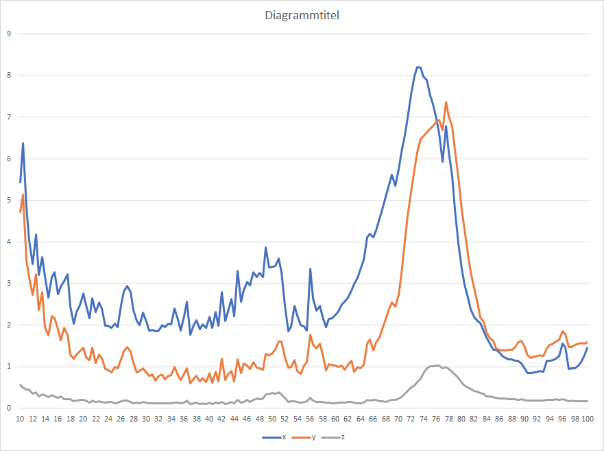
In between the two measurements only one 6h print job and quite some vibration measurments took place. No modification otherwise.
Reason is not measuring, because SHAPER_CALIBRATE, TEST_RESONANCE and TEST_VIBRATIONS more or less agree. Maybe the "extensive" vibration testing shifted some belt tension etc? I don't know and didn't find any obvious reason.
Data Package: https://drive.google.com/file/d/1xNDu3sgfIWgR_g6SXegw2_Sy4-tyBvgR/view?usp=sharing
Sineos
on 3 Sep 2020
@Sineos
- XY will crash
You can try running the tests separately, i.e. with AXES=X and AXES=Y, and save the results to the config afterwards.
- Minor point: the error message when the [input_shaper] section is missing is quite cryptic
Can you elaborate on this one?
Maybe the "extensive" vibration testing shifted some belt tension etc?
Maybe. I can actually see that prolonged exposure to strong vibrations may increase the wear of the printer parts. Normally a user shouldn't need to run the vibration test for hours every day though.
dmbutyugin
on 3 Sep 2020
Can you elaborate on this one?
For my first attempts with SHAPER_CALIBRATE I commented the entire [input_shaper] section in the config to avoid polluting the results with an existing shaper configuration. This leads to
Internal error on command:"SHAPER_CALIBRATE"
Traceback (most recent call last):
  File "/home/pi/klipper/klippy/gcode.py", line 177, in _process_commands
    handler(gcmd)
  File "/home/pi/klipper/klippy/gcode.py", line 115, in <lambda>
    func = lambda params: origfunc(self._get_extended_params(params))
  File "/home/pi/klipper/klippy/extras/resonance_tester.py", line 210, in cmd_SHAPER_CALIBRATE
    input_shaper = self.printer.lookup_object('input_shaper')
  File "/home/pi/klipper/klippy/klippy.py", line 95, in lookup_object
    raise self.config_error("Unknown config object '%s'" % (name,))
Error: Unknown config object 'input_shaper'
Transition to shutdown state: Internal error on command:"SHAPER_CALIBRATE"
Reading the Traceback quickly reveals the issue. It could be a bit more user friendly. But as already said: Very minor point since this is bleeding edge after all. I just thought I share it, in case other willing testers stumble over it.
Sineos
on 4 Sep 2020
@dmbutyugin - Some random high-level thoughts on the resonance_tester implementation:
- I'd be leery about specifying a filename directly on the g-code commands, for fear of security implications should a bad filename be specified. In general, I think it would be safer if the code specified the filenames instead of the user.
- The latest graphs are very useful. I do think they are a bit "busy" though. As a random idea, maybe only show "X+Y+Z", estimated X+Y+Z after zv, estimated X+Y+Z after mzv, after ei, etc.
- I'm not sure I'd generate graphs directly from klippy. In the future I suspect we'll be moving move more towards "webhooks" interfaces than raw g-code command line interfaces. These "webhooks" interfaces typically prefer the raw data so that they can use their own graphing and inspection tools.
- It would be useful to support a
CHIP=parameter to the resonance testing commands so that one can define multiple accelerometers in their config.
Again, just some random thoughts.
-Kevin
KevinOConnor
on 4 Sep 2020
OK, I've rebased the branch on top of new changes from Kevin, and additionally moved the heavy calculations into different processes. This should hopefully resolve the occasional timing errors.
@KevinOConnor I agree with most of your points. For experimentation it was useful to have a possibility to write the specified files (especially since some of them could be large, and it is not clear if some default locations, like /home or /tmp are a good idea), but shaper_calibrate should mostly remove this need for most of the users. And if webhooks can render the plots - I'm fine with that too. However, I do not think it will be possible to remove the dependencies on additional modules. At the very least, numpy dependency will have to stay, and maybe instead of using matplotlib functionality (specgram calculation) we could migrate to calling some more low-level stuff from scipy module directly.
Separately, I plan to add some configuration options to the resonance tester, such as probe points, chip/axis, etc, so that one only normally needs to execute shaper_calibrate without extra parameters needed (similar to, say, delta_calibrate).
dmbutyugin
on 4 Sep 2020
I ran a test on my delta
command:
SHAPER_CALIBRATE PROBE_POINTS=0,0,20:0,80,20:69.26,-40,20:-69.28,-40,20 AXES=XY RAW_OUTPUT=/tmp/accel-data.csv FIG_BASENAME=/tmp/shaper_calibration.png
The command finished but did not output - accel-data.csv "I ran out of resources" but it did output the pics
User Error - I did not expand the file system after first boot.
Recommended shaper_type_x = 2hump_ei, shaper_freq_x = 62.9 Hz
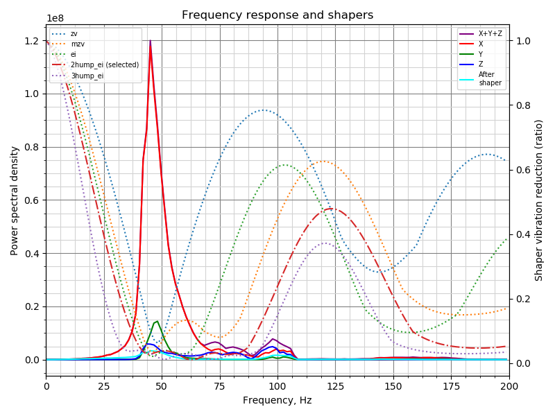
Recommended shaper_type_y = 2hump_ei, shaper_freq_y = 63.7 Hz
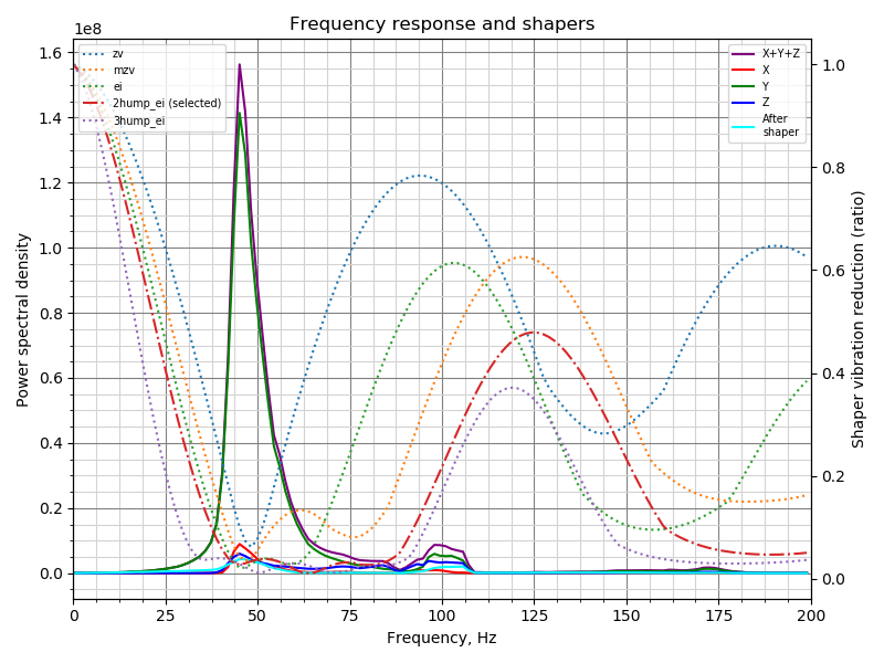
BlackStump
on 7 Sep 2020
@BlackStump
The suggested shaper configuration looks OK to me, at least looking at the frequency chart. Did you try to use the suggested configuration? The calibration code also dumps the suggested parameters for other shapers; it looks like MZV shaper at ~46 Hz should also probably work well in your case (and EI shaper at ~53 Hz), according to logs.
As for the raw logs, indeed I changed the code to not generate raw data for shaper calibration. It takes considerable amount of time and space to write those logs, and currently it is not worth the trouble to implement partial data writes in a separate process.
Separately, I am working now on some code refactoring and updating the documentation accordingly.
dmbutyugin
on 9 Sep 2020
@dmbutyugin
No I have not actually tested the printer with the suggested shaper configuration as yet, trying to hookup a pi-zero over serial so I can un-tether the Pi4, maybe in a couple days I will get some test prints done.
I did see the other suggestions and have them recorded to test and compare in due course.
cheers
BlackStump
on 9 Sep 2020
OK, I've updated the branch. The documentation is also updated. Most notably, you will need to update the config a bit, e.g.
[mcu rpi]
serial: /tmp/klipper_host_mcu

[adxl345]
cs_pin: rpi:None

[resonance_tester]
accel_chip: adxl345
probe_points:
    100,100,20  # an example
Afterwards, you can run the tuning with simply SHAPER_CALIBRATE FIG_BASENAME=/tmp/calibration.png (or also supplying AXIS=... parameter on the bed slinger to run the test only for the specific axis). There is also now a support for dual ADXL345 setups (i.e. with one for X axis and one - for Y, which can be useful on bed slinger printers, as long as you can connect both simultaneously).
dmbutyugin
on 12 Sep 2020
One other thing: I have added a support for a different test method, at least temporarily - Moore curve method. In this case, the toolhead is made to follow the Moore curve, and the accelerometer measures the excited vibrations. Honestly, I do not think it is a a very good way to auto-calibrate input shapers - it is not easy to distinguish X and Y axis vibrations from each other. However, maybe it can be used to check the input shaper configuration? So, if you have some spare time and want to give it a try, here's how you can do it.
Add/replace the following section to printer.cfg:
[resonance_tester]
accel_chip: ...
# Moore curve test parameters
method: moore
order: 5
runs: 1
# An example for delta printer
xmin: -50
ymin: -50
xmax: 50
ymax: 50
z: 30
Replace xmin/xmax and ymin/ymax with values that work for your printer. I would suggest to specify a square of size 50-100 mm in the middle of the buildplate.
Then you can disable input shaper (or not) and run the test
SET_INPUT_SHAPER SHAPER_FREQ_X=0 SHAPER_FREQ_Y=0
TEST_RESONANCES FIG_BASENAME=/tmp/resonances.png
My personal experience: I got pretty decent results with
- square 100 x 100 mm
- order = 5
- max_accel = 7000 mm/sec^2
If you give it a try, I would suggest you to try the square with the side of approx. 50-100 mm, and order = 4, 5, and 6. max_accel - maybe around 5000-10000 mm/sec^2.
Some results on my printer, with the parameters above and input shaper - 2hump_ei at 59 Hz on both X and Y axes:
| 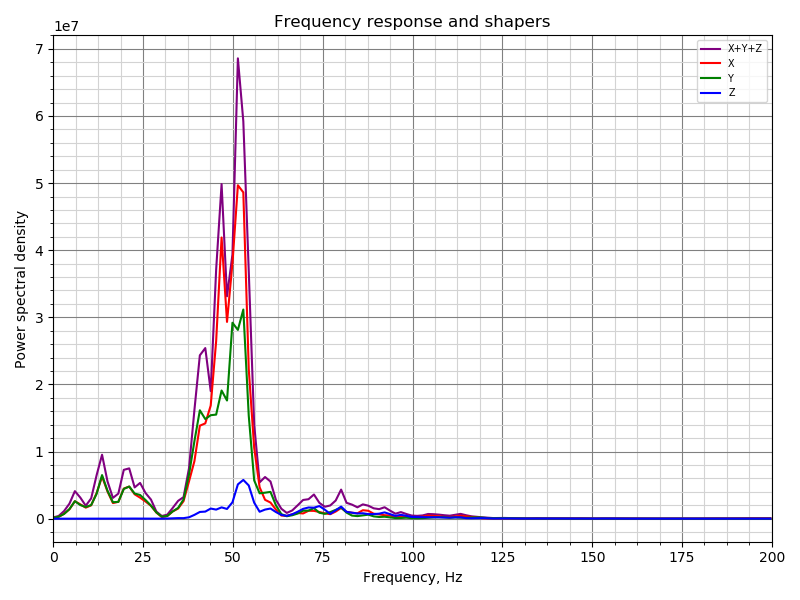 |
| 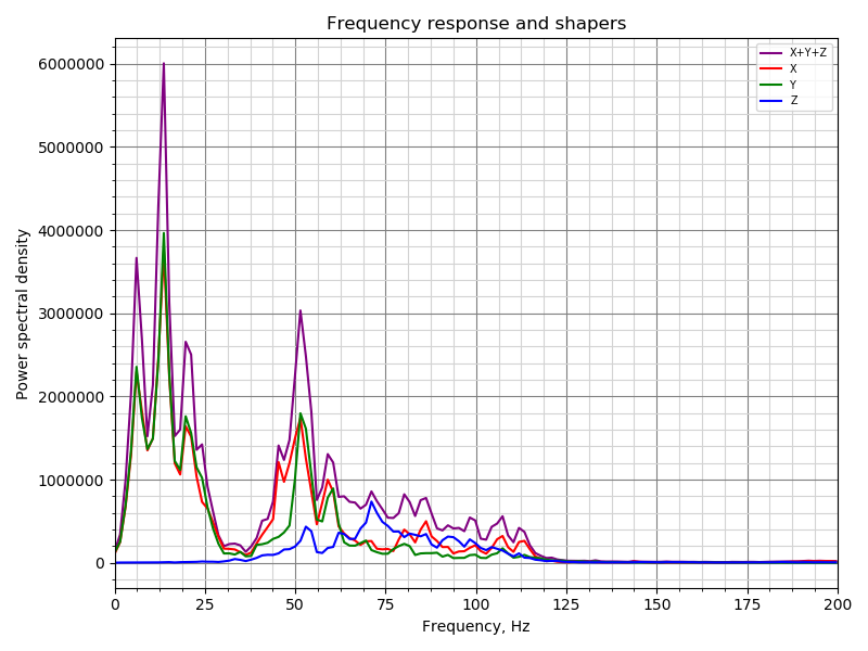 |
|
|:---:|:---:|
|input shaper disabled | input shaper enabled |
And comparison of several damping ratios (equal for both axes):
| 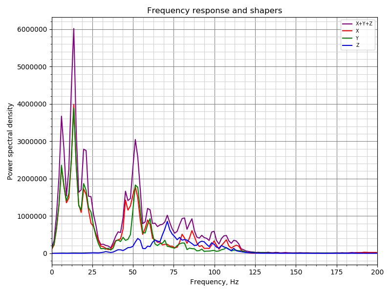 | |
| | 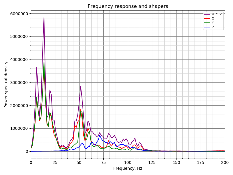 |
| 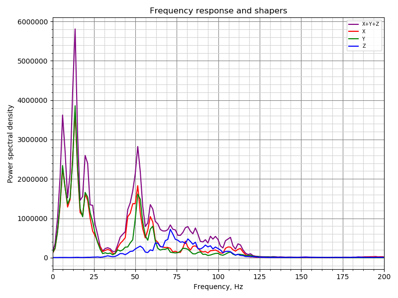 |
| 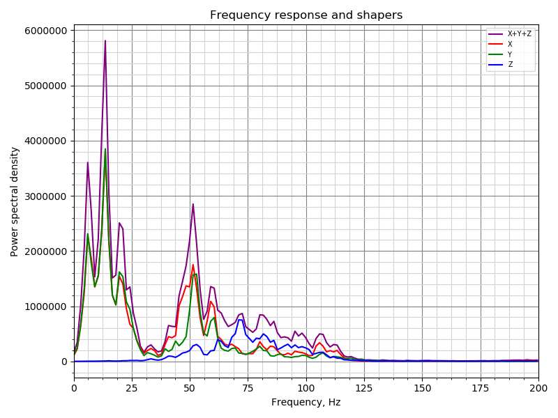 |
|
|:---:|:---:|:---:|:---:|:---:|
| damping_ratio=0.15 | damping_ratio=0.1 | damping_ratio=0.075 | damping_ratio=0.05 | damping_ratio=0.025 |
So, there is very clear effect of the input shaper (the amplitude of resonances around 50 Hz drops by ~20x), but there is only minor influence of damping_ratio parameter (it would seem that the vibrations slightly decrease around 0.05-0.075, but only tiny bit). The results show relatively good repeatability (though sometimes they do vary for whatever reason). I also think that the vibrations in the range 0-25 Hz are just the real toolhead vibrations due to the test movements, and are not the real resonances.
dmbutyugin
on 12 Sep 2020
An update on my side. I was concerned that the older control board on my Makergear M2 printer was a cause of some resonances (specifically, it has older A4984 stepper drivers that only support 8x microsteps). So, I swapped out the control board on the printer for a Duet2 Maestro with tmc2208 drivers.
I am seeing a noticeable improvement in the resonance test with the new board. Here's a graph comparing the old A4984, to the new board with spreadcycle, and with stealthchop:
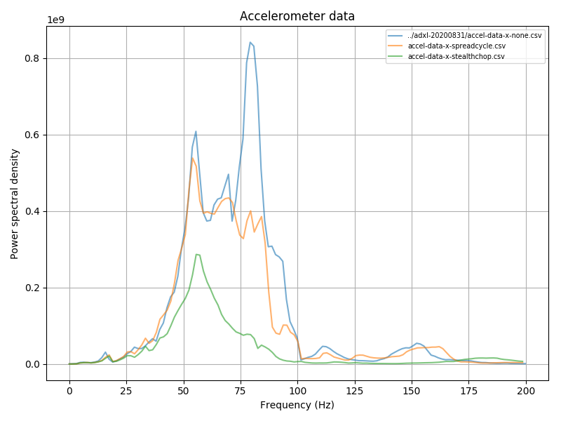
I'm not surprised on the improvement with spreadcycle (and 16 microsteps interpolated to 256), but it is interesting that stealthchop shows such an improvement over spreadcycle. I'm not sure if this is an actual improvement or if spreadcycle is filtering some of the motor movement during the resonance test itself.
FWIW, I did also try a bunch of different settings with iterpolation and microstep settings while using spreadcycle. I can see some minor differences, but it would seem random noise dominates the results.
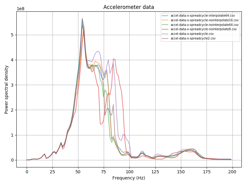
None show anything similar to the single bump that stealthchop shows.
I hope to swap out the hotend on this printer some time later this week. Also looking to go to a new 24 power supply at some point in the future as well (my M2 uses 19V for the steppers).
-Kevin
KevinOConnor
on 14 Sep 2020
BTW, I pushed another change which adds more docs, and some small update to the file parameters of the commands, e.g.:
TEST_RESONANCES AXIS=X FIG_NAME=resonances.png CSV_NAME=resonances.csv RAW_NAME=raw_data.csv
SHAPER_CALIBRATE FIG_NAME=calibration.png CSV_NAME=calibration.csv
Now, it would be great if more folks could try SHAPER_CALIBRATE autocalibration, tried the suggested parameters in test and real prints and shared their experience.
dmbutyugin
on 16 Sep 2020
I have made a change to the input_shaper calibration code to divide the calcuated PSD by the frequency of a specific bin. There are 2 motivations behind this change:
- When running the test, the acceleration is calculated as frequency * accel_per_hz, so it increases already as the frequency increases. Increasing acceleration with frequency is needed because, generally, the amplitude of vibrations decreases as freq^-2, so unless compensated (even if a bit - by one power of freq), the amplitude will quickly become less than 1 step of a stepper motor; and using maximum acceleration for all frequencies is not really necessary (and can probably damage a printer with low resonance frequencies).
- Generally, the amplitude of vibrations decreases as the resonance frequency increases.
It is an open question whether PSD / freq is enough, or if we should be using larger power for freq, e.g. PSD / freq^2. However, freq^2 seems to amplify low-frequency noise, and probably does not make too much sense, so I guess that PSD / freq is a reasonable compromise.
Also, in one of the previous commits I have added back the ability to write the raw accelerometer measurements during the test (not the automatic shaper calibration), so if you are running tests, I suggest to capture those too, e.g. via
TEST_RESONANCES AXIS=X RAW_NAME=raw_data.csv FIG_NAME=response.png CSV_NAME=response.csv
Then the raw data can be re-processed either using Kevin's tool from #3323, or via
$ ~/klippy-env/bin/python klipper/klippy/extras/shaper_calibrate.py /tmp/raw_data_x_*.csv
(and similarly for Y axis).
Also, if you used automatic shaper tuning, please share how the suggested parameters work in real-life prints.
dmbutyugin
on 18 Sep 2020
Hi there. Thanks for all of the effort on this. Just wanted to mention that I have, just today, played around with shaper_calibrate. Thus far I have only printed the resonance test tower, but the results were astonishing.
Previously, I empirically measured and compensated for resonance using the procedure details here. I went as far as fine tuning the results. I should mention that even with no input shaping, my prints weren't bad. My measured frequencies were 52hz in X and 38.1hz in Y.
Manual Resonance Compensation
No Input Shaper
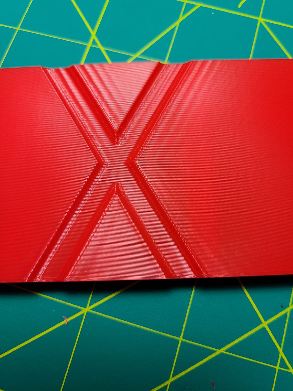
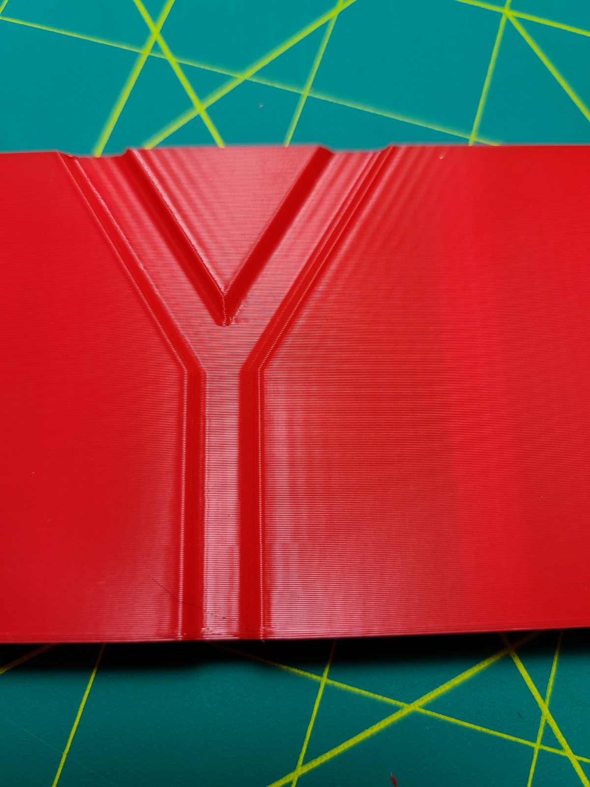
EI Input Shaper Applied

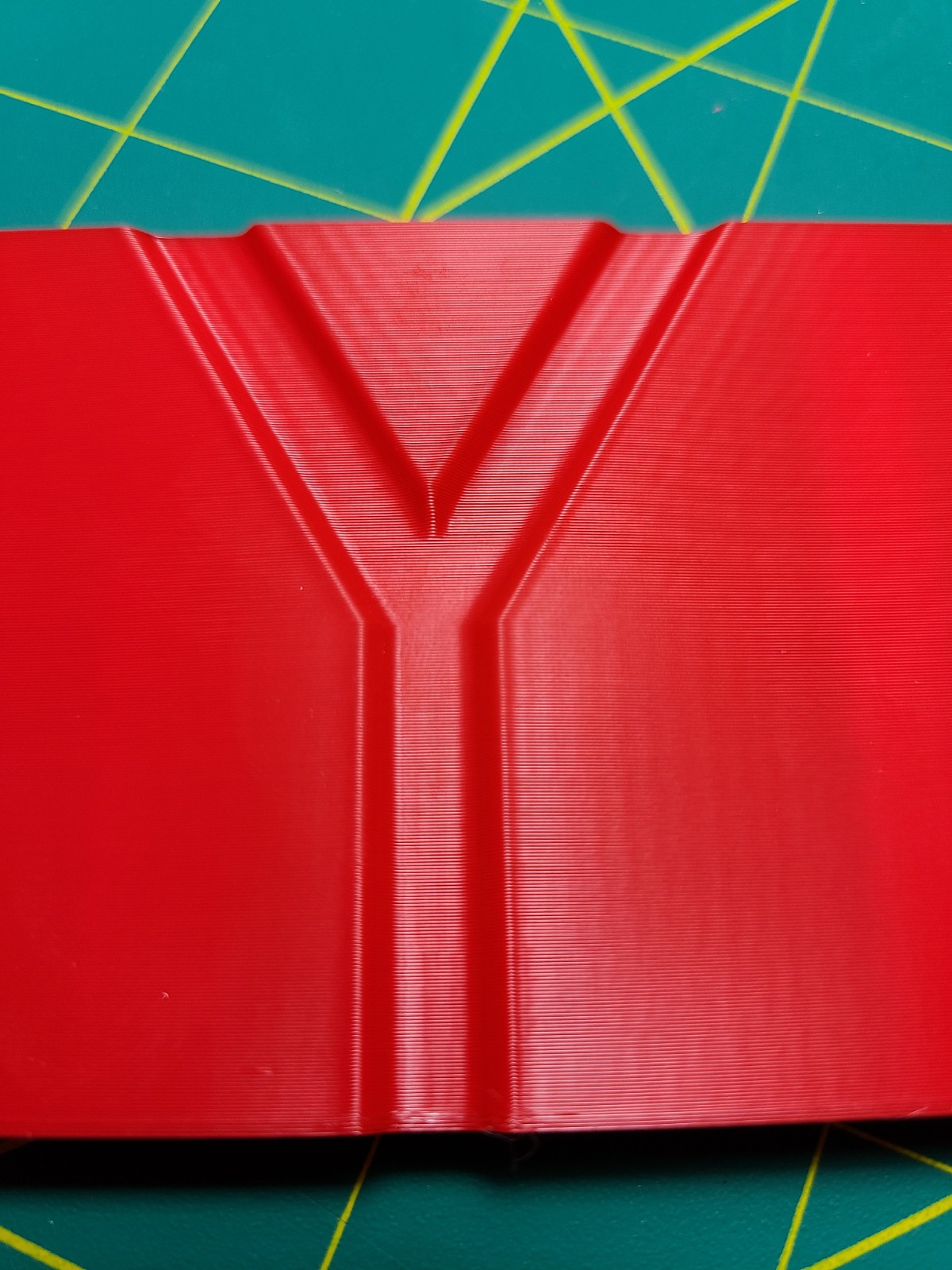
This was with the above mentioned frequencies. Results are pretty good and not until about 4000mm/s^2 did I see any ringing. However, in practice when printing pieces at 4000mm/s^2 and 150mm/s I did still see some ringing at the same frequencies but only in the Y axis.
I wanted to see what we could do with @dmbutyugin adxl345 branch and the shaper_calibrate command. I first tested resonance frequencies with the empirically determined input_shaper.
Resonance Test Outputs
X Axis - with input shaper
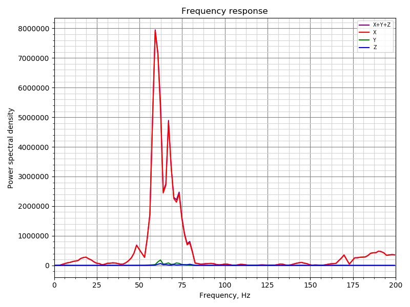
You can still see a peak, around where the shaper should be applied.
X Axis - without any input shapers
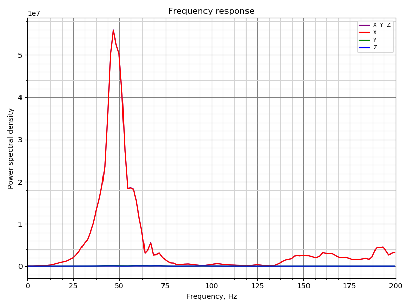
Y Axis - with input shaper
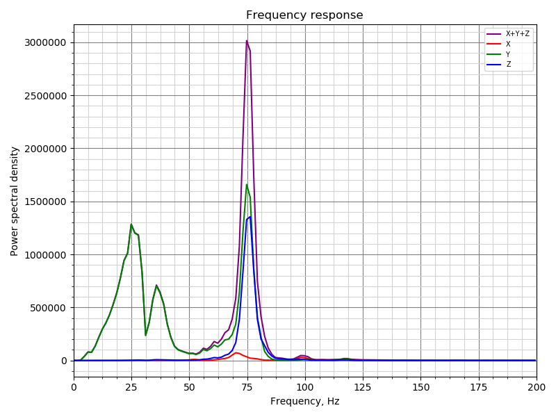
You can see a lot of cross talk between the Y/Z axes at around 75hz. And still not fully compensated for my peak at 38hz. And interestingly, a peak at 25hz appears.
Y Axis - without any input shapers
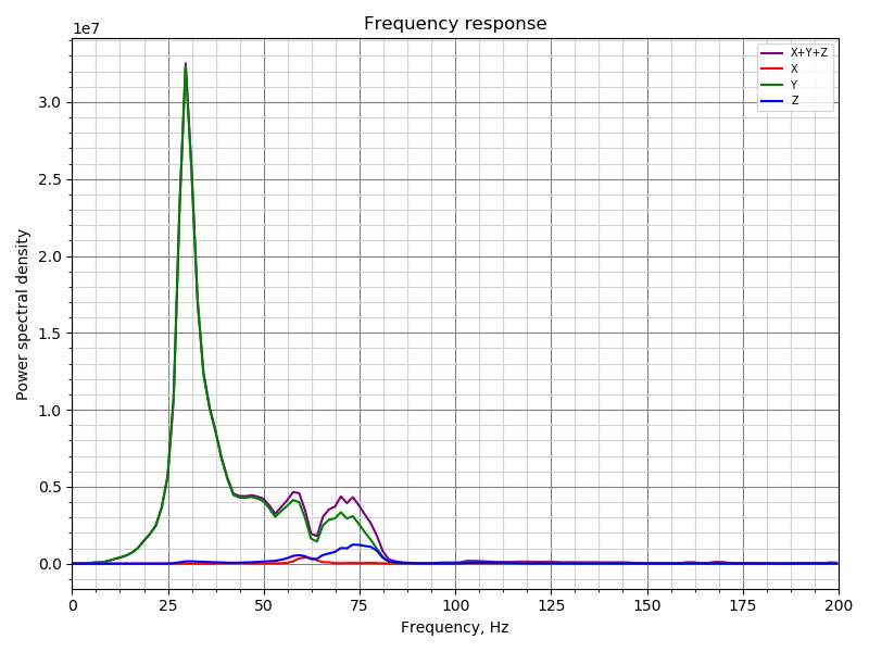
Note very little cross talk between Y and Z.
The results without any input shapers applied are close to what I expected to see from my manual measurements.
Calibration Outputs
X Axis
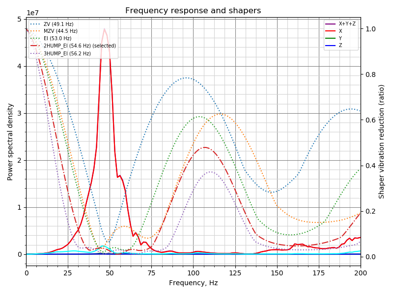
Y Axis
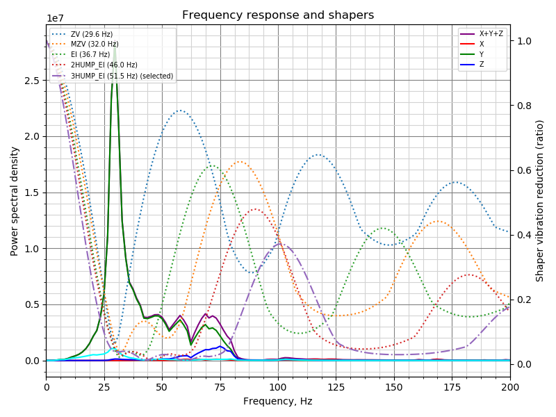
The automatic calibration suggested frequencies for EI were pretty much spot on with what my fine-tuning lead me to.
Tower
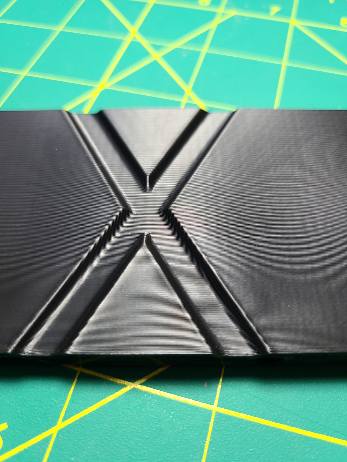
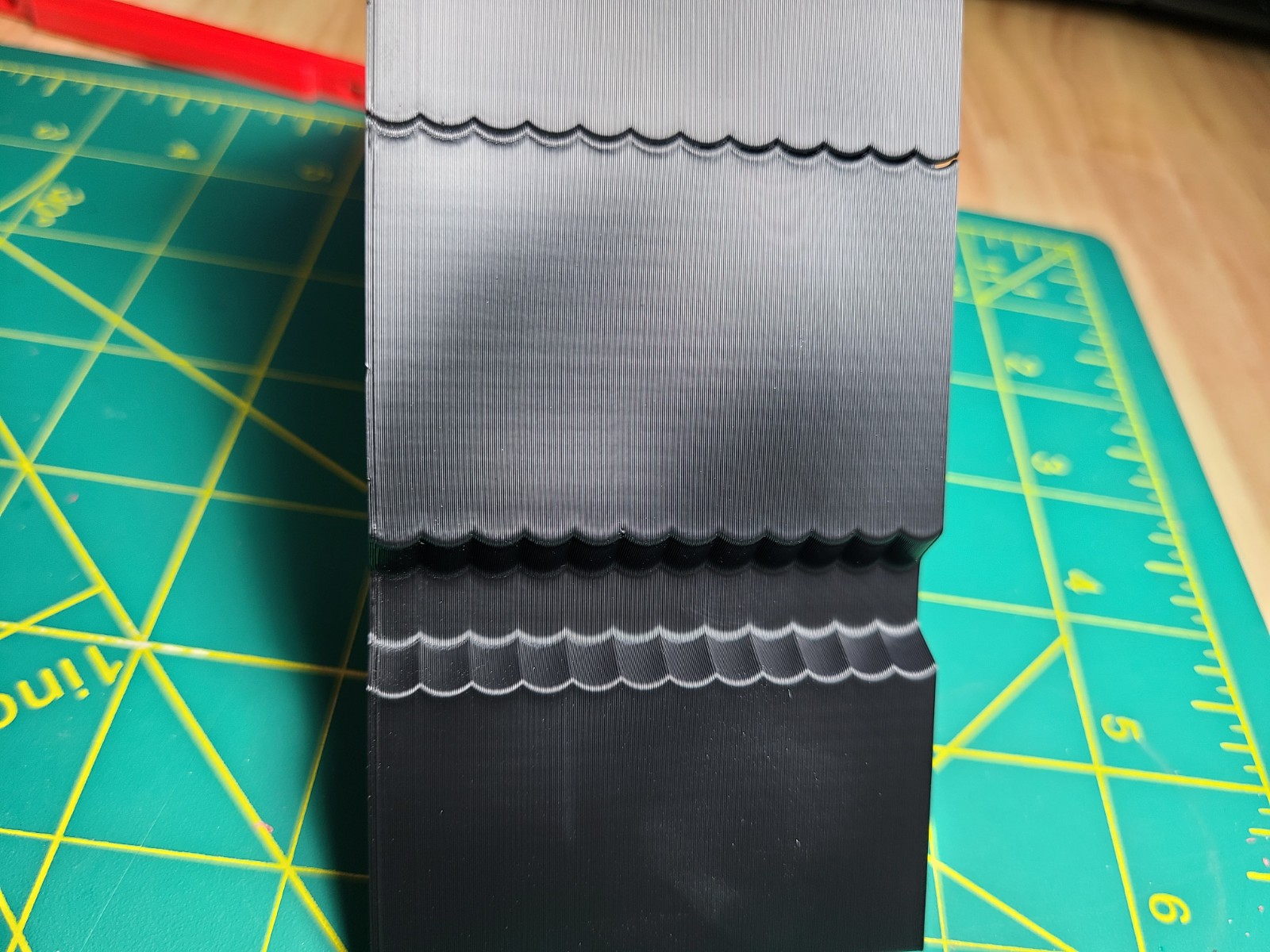
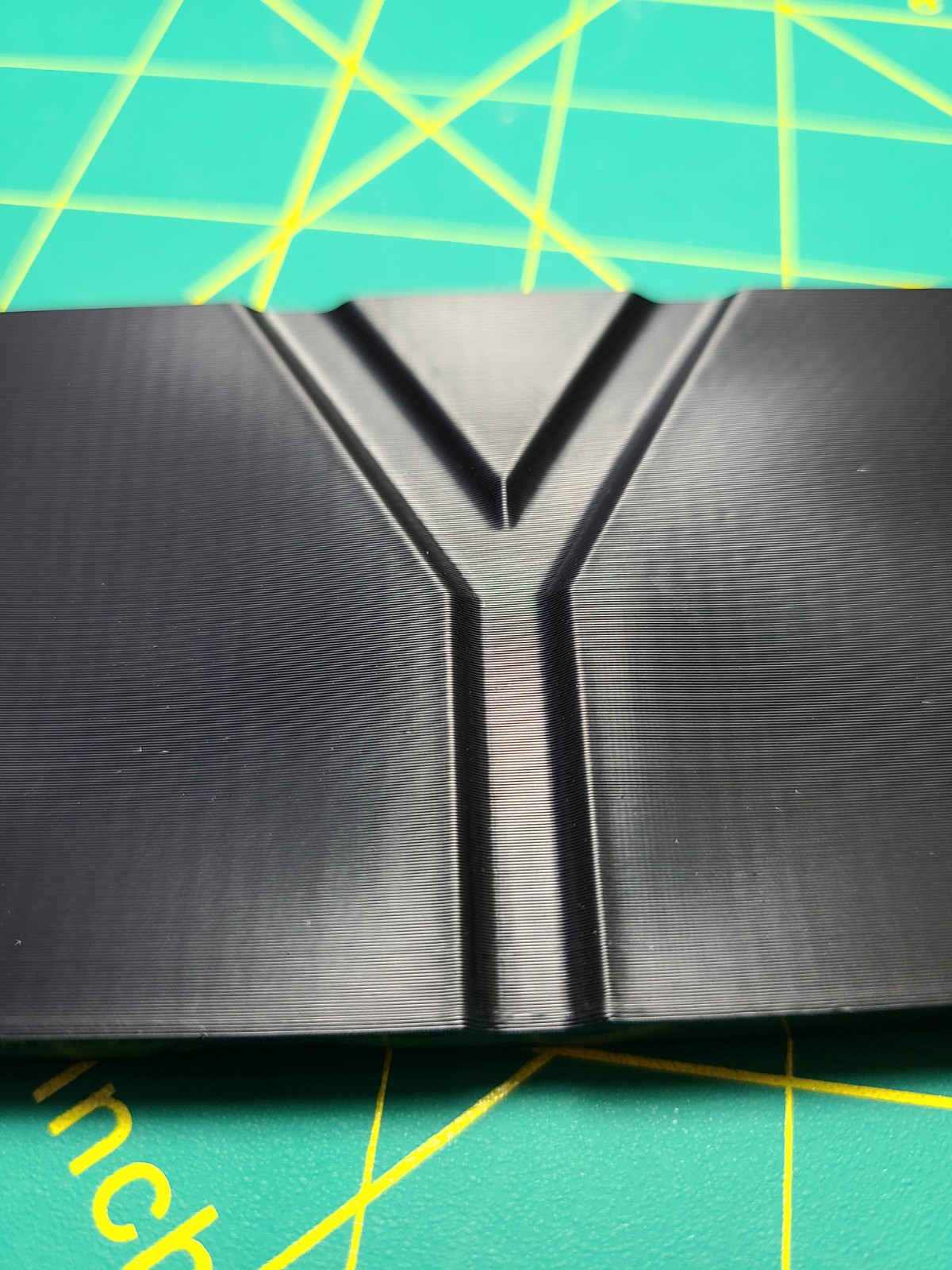
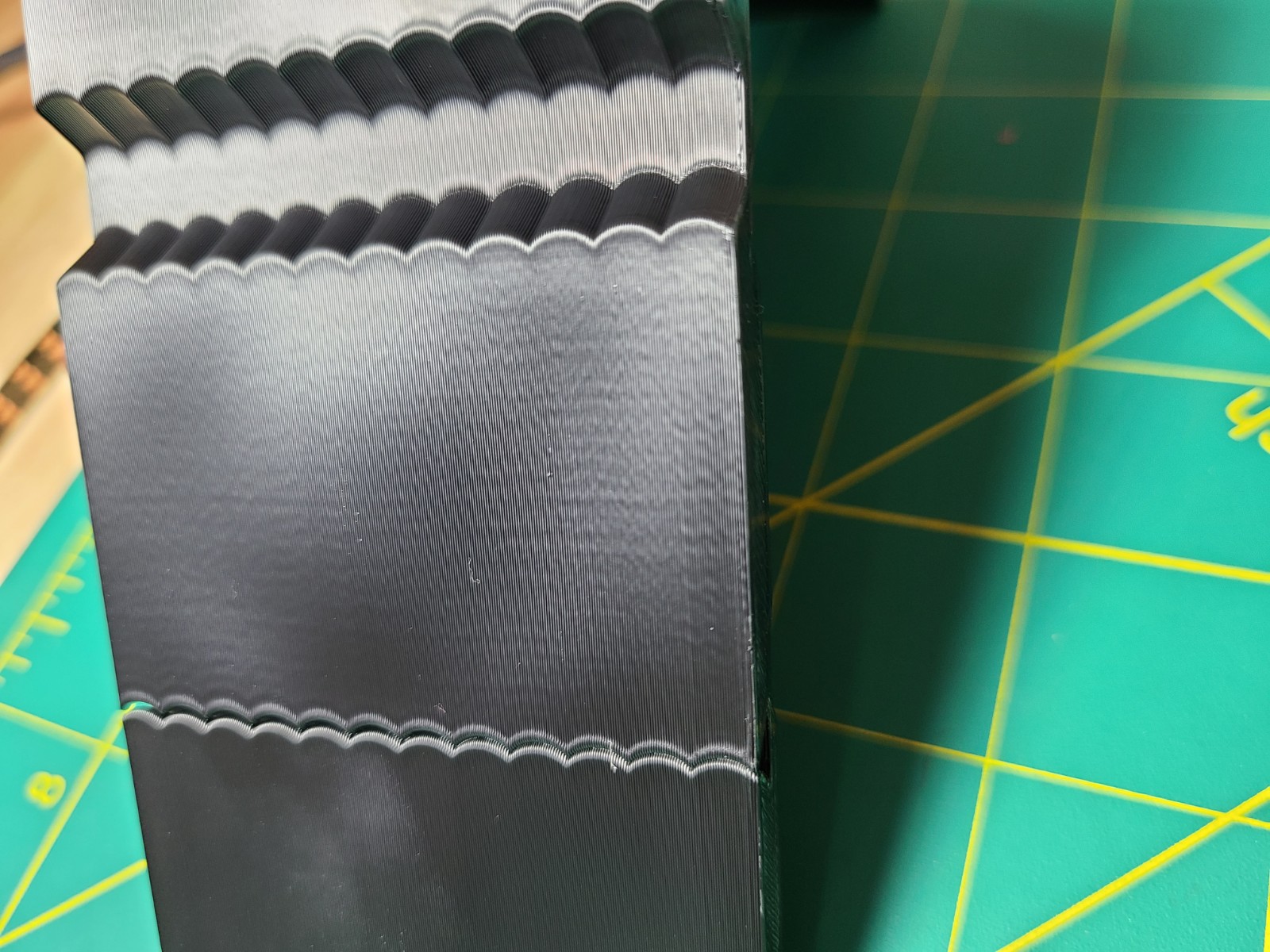
To be completely honest, the results are kind of astonishing! Great job you two. I'm printing a test piece at 4000mm/s^2 and 150mm/s right now and will share the results when complete.
One thing to note, is that at times, the device id returned from the adxl345 is returned as 0xF2 instead of 0xE5, only some of the time though. This 0xF2 is the same value I get when I read the device ID directly using pigs or alternate methods when setting the R/W bit. Reading address 0x00 by sending 0x80. However, if I don't set the R/W bit I consistently get 0xE5 as the response.
Other than that things work pretty smoothly on my single rpi4 running everything. With the exception of sometimes hanging when trying to communicate over the spi bus - but killing pigpiod eliminates the hanging immediately.
 seth-cohen
on 18 Sep 2020
seth-cohen
on 18 Sep 2020
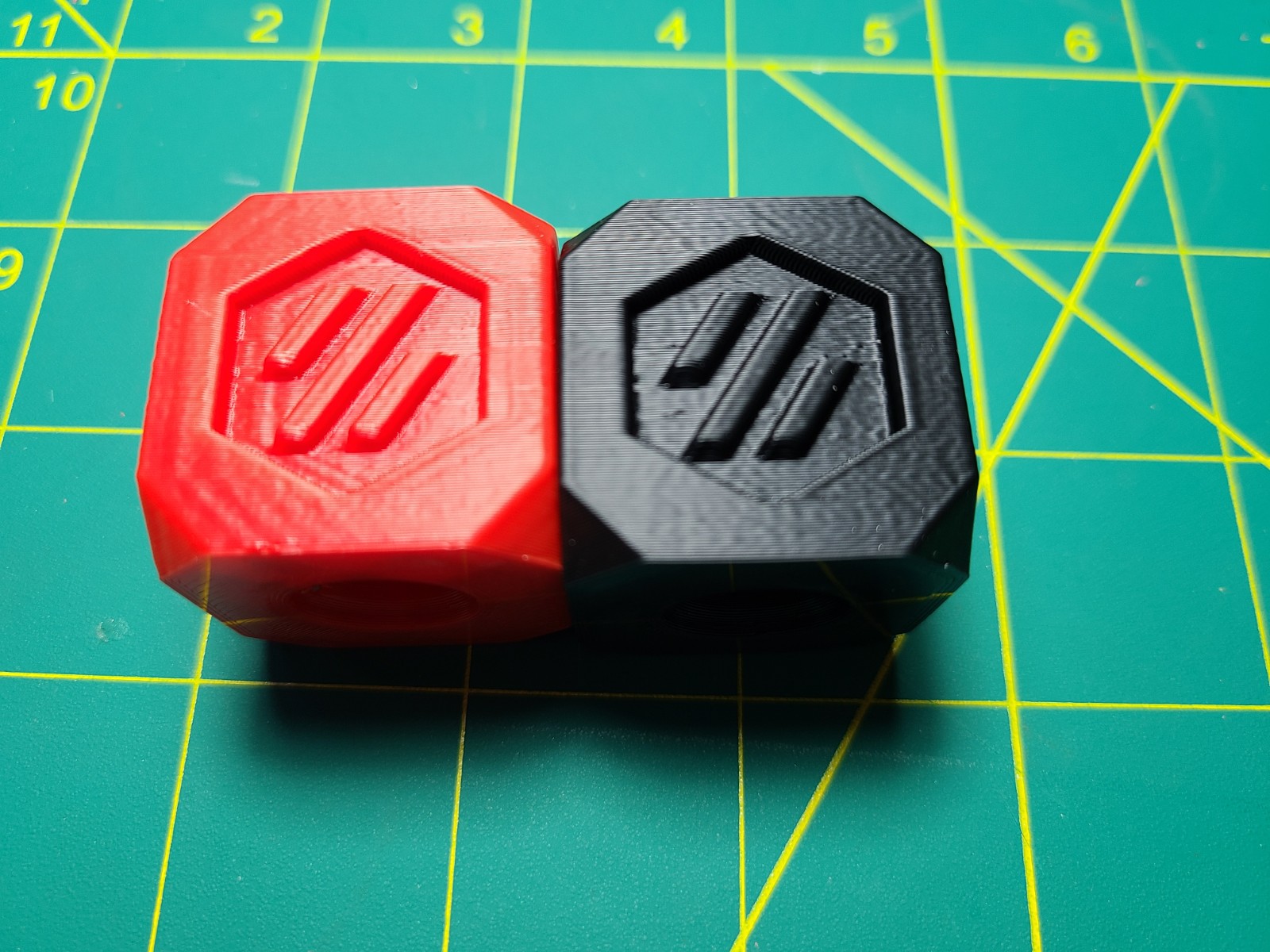
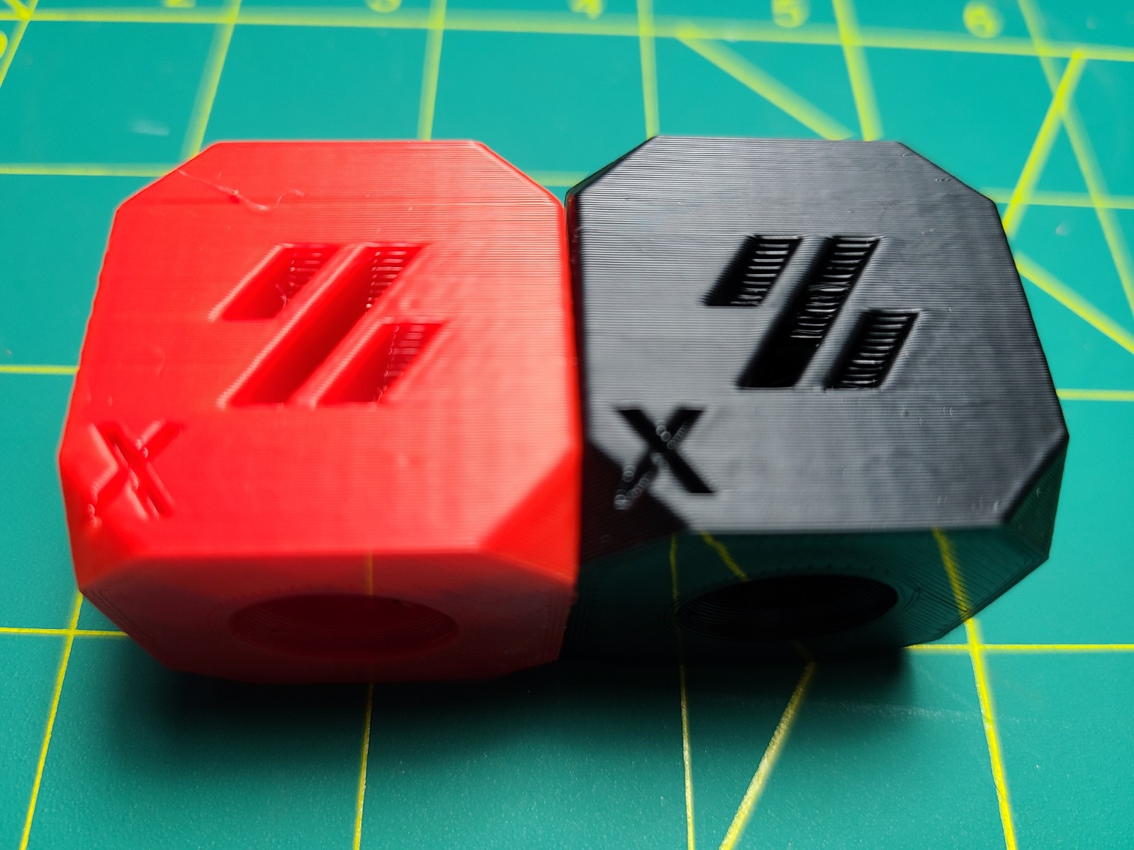
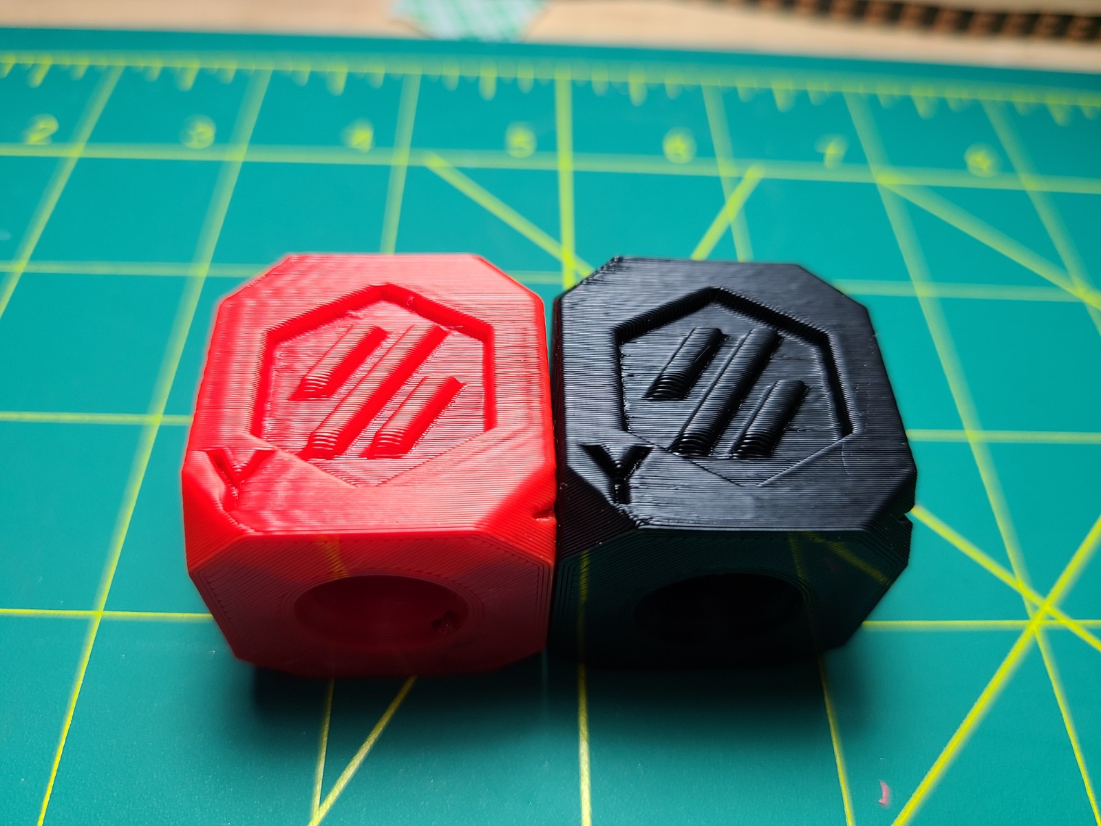
Looks great.
| | Left (Red) | Right (Black) | Note |
|- |- |- |- |
| Speed | 150 mm/s | 150 mm/s | Including outer wall |
| Accel | 3000 mm/s^2 | 4000 mm/s^2 | |
| Shell | 2 Walls | 2 Walls | Top/Bottom 2 Walls |
| Infill | 12% | 12% | |
| Shaper | X: EI (52hz)
Y: EI (38.1hz) | X: 2hump_ei (54.6hz)
Y: 3hump_ei (51.5hz) | Right is the auto calibrate suggested settings |
seth-cohen
on 18 Sep 2020
Today I realized that all the branches in my repo can be confusing (which branch to use for resonance tuning and shaper calibration). So to avoid confusion, I deleted the old version of adxl345-spi branch, and pushed a new version of the code (which was previously in my work-adxl345-20200730) to adxl345-spi branch. So, if you want to try the resonance testing, please use adxl345-spi branch now.
dmbutyugin
on 19 Sep 2020
@seth-cohen Thanks for sharing your experience! Your results also demonstrate that while the simple ringing test is pretty good at catching the main resonance, it is possible that there are other, weaker resonances, which the accelerometer may be able to pick up, and a better configuration can be created. It is also great that the auto-tuning seem to have worked very well for your case.
BTW, I understand that you've run the shaper calibration code before I pushed this change 'I have made a change to the input_shaper calibration code to divide the calcuated PSD by the frequency of a specific bin.', right? If yes, could you try, when you have time, run the shaper autocalibration again and post the results here?
One thing I wanted to clarify: which input shapers did you use for your 'Resonance Test Outputs'? The ones that were automatically calibrated, or your previous configuration with EI shaper? If EI shaper, then
You can see a lot of cross talk between the Y/Z axes at around 75hz. And still not fully compensated for my peak at 38hz. And interestingly, a peak at 25hz appears.
Is not surprising, as EI shaper in that configuration wouldn't be able to compensate 75 Hz resonance.
Separately, running resonance testing (at least the default test) with input shaper enabled is not truly valid, and you may get some strange results (like that peak at 25 Hz). However, it is still interesting to see the results. And for X axis
You can still see a peak, around where the shaper should be applied.
That's true, but the magnitude of that peak seems to be 10x smaller.
One thing to note, is that at times, the device id returned from the adxl345 is returned as 0xF2 instead of 0xE5, only some of the time though. This 0xF2 is the same value I get when I read the device ID directly using pigs or alternate methods when setting the R/W bit. Reading address 0x00 by sending 0x80. However, if I don't set the R/W bit I consistently get 0xE5 as the response.
Other than that things work pretty smoothly on my single rpi4 running everything. With the exception of sometimes hanging when trying to communicate over the spi bus - but killing pigpiod eliminates the hanging immediately.
Note that the new version of the code does not require pigpiod, so you don't need to run it anymore (and/or install it). Maybe you got some occasional errors about the address because you ran it?
dmbutyugin
on 19 Sep 2020
BTW, I understand that you've run the shaper calibration code before I pushed this change 'I have made a change to the input_shaper calibration code to divide the calcuated PSD by the frequency of a specific bin.', right? If yes, could you try, when you have time, run the shaper autocalibration again and post the results here?
I would say that it is likely true that I ran that prior to the update. I am running on commit a5ed5115a147867fe0df0122a5f0dedfc8aeadbf (HEAD, s-curve-exp/work-adxl345-20200730). I will run it again, just need to wait for some prints to stop.
Also, funny side effect, I'm able to run at such speeds with keeping such clean lines that right now the limiting factor is my extruder motor/hot_end (haven't isolated which yet).
One thing I wanted to clarify: which input shapers did you use for your 'Resonance Test Outputs'? The ones that were automatically calibrated, or your previous configuration with EI shaper?
Yes I was running EI for the Resonance Output figures with the Input Shaper on. I simply forgot to disable, before running it the first time.
Maybe you got some occasional errors about the address because you ran it?
That is possible, it is really odd that with pigs I can easily reproduce, by setting the R/W bit (which as I understand SHOULD be set to read the device id). I'm not digging into this one, since things work.
seth-cohen
on 19 Sep 2020
I did a tune with the most recent code and after I tightened my belts a bit. The change in the chart is interesting. The Old charts were looser belts (pretty floppy) and the new charts are a bit tighter.
Old, Loose X:

New, Tighter X:
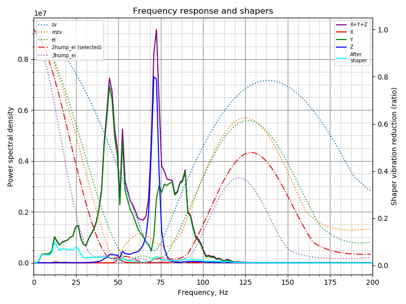
Old, Loose Y:
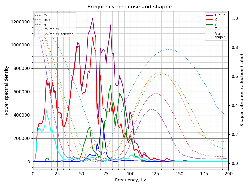
New, Tighter Y:
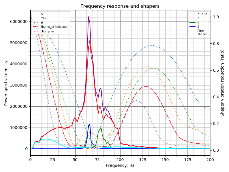
Going to do a few prints with the new tune.
natewalck
on 20 Sep 2020
@natewalck Thanks! It is interesting how tensioning the belts affected the results. Also, are you sure you are running the latest code? The new charts should show the frequency for each input shaper in the chart (e.g. "ZV (60 Hz)"). Note that you need to use 'adxl345-spi' branch now.
dmbutyugin
on 20 Sep 2020
Yep, it's the latest branch. I did each axis individually because last time I had issues running both X and Y in the same run without lowering the sample rate. Not sure if that impacted it.
I can retry doing both XY at the same time.
natewalck
on 20 Sep 2020
@natewalck, would you mind also posting the result of these commands:
$ cd klipper
$ git status
? Now I think all the issues running test both for X and Y should be resolved, and you don't need to lower the sampling rate from the default 3200 (as long as you have connected the sensor to the Rasperry Pi itself).
dmbutyugin
on 20 Sep 2020
pi@mainsailos:~/klipper $ git remote -v
origin  https://github.com/dmbutyugin/klipper.git (fetch)
origin  https://github.com/dmbutyugin/klipper.git (push)
pi@mainsailos:~/klipper $ git status
On branch adxl345-spi
Your branch is up to date with 'origin/adxl345-spi'.

nothing to commit, working tree clean
I pulled the latest from your github @dmbutyugin. I'm currently running on commit 13829b8a349b5d7b7d9c820db43e27632b88e509.
One note - I think some of the Y/Z axes cross talk might be due to the adafruit breakout board design. 
With the only mounting holes being at the +Y axis, and on the opposite side of added mass of wires and connection, I could imagine that moment and a rotational force around the X-Axis. I might try and design a better mount with a clamping mechanism to positively fix the board.
I reran calibration on this commit. In the time my belts had since loosened, so I did tighten them as well. I'm sure that would have an impact on the results.
Updated Calibration Outputs
X-AXIS
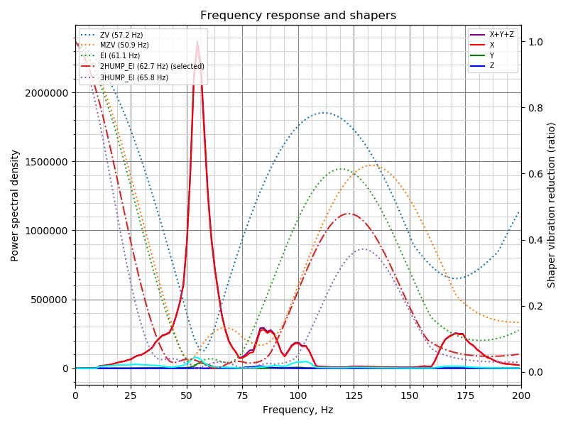
Y-AXIS
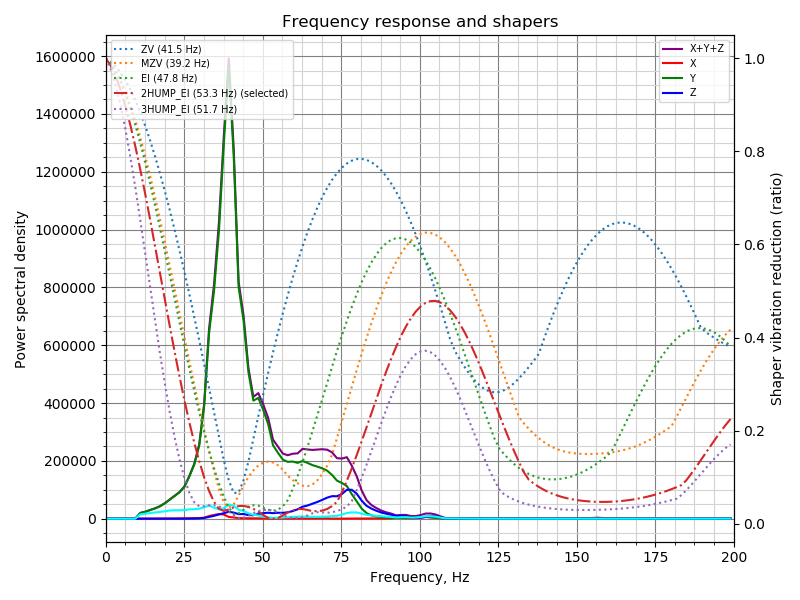
Ringing Model with Suggest Shaper Applied & Practical Test Print
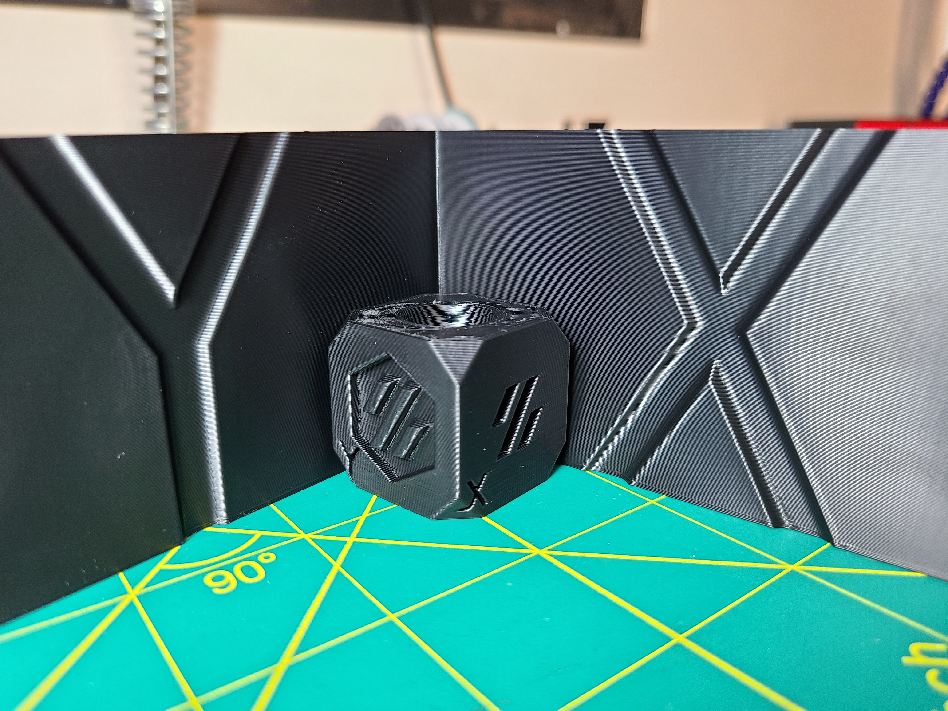
Test Print: 120mm/s (everywhere), 4000 mm/s^2.
Once again, results look great. Not sure if there is anything else you'd like to see.
seth-cohen
on 21 Sep 2020
@natewalck OK, thanks! Can you share your experience with using these automatically suggested parameters? How good or bad the prints are?
@seth-cohen
I reran calibration on this commit. In the time my belts had since loosened, so I did tighten them as well. I'm sure that would have an impact on the results.
Yes, it looks like the resonance frequencies increased since the last time. Especially on Y axis from ~30 Hz to ~40 Hz it should have a positive impact on the quality and the 'smoothness' of the parts.
One note - I think some of the Y/Z axes cross talk might be due to the adafruit breakout board design.
With the only mounting holes being at the +Y axis, and on the opposite side of added mass of wires and connection, I could imagine that moment and a rotational force around the X-Axis. I might try and design a better mount with a clamping mechanism to positively fix the board.
In principle, that's possible. Generally, there could also be other reasons: a bit misaligned sensor (so the axes are not exactly aligned with the axes of the printer), etc. However, sometimes we observe the interesting cases when the resonances from another axis (non-main axis for the current print) do not just follow the main resonances, but instead have their own peaks, like in these results from @natewalck:
I think in this case it is safe to assume that indeed X axis vibrations at ~70 Hz can excite the vibrations in Z direction.
@KevinOConnor I committed a change to use Welch's algorithm (the averaging) to calculate the frequency response. BTW, what is your opinion of the development of this feature? Do you see a value in integrating this resonance test and shaper autocalibration any time soon? After some code cleanups, I'd say. I have also written a short implementation of Welch's algorithm using NumPy only (but not committed it yet), so if the library function works well, I will submit this code; this will allow us to only add a dependency on NumPy for RPi installations, as long as the users won't plot the charts on the device. We can still have the 'matplotlib' dependency as optional.
dmbutyugin
on 22 Sep 2020
BTW, what is your opinion of the development of this feature? Do you see a value in integrating this resonance test and shaper autocalibration any time soon? After some code cleanups, I'd say.
It seems like useful functionality that I think would be good to merge.
That said, the obvious question I would ask: Is the cost and complexity of adding this to klippy.py worth the user improvement that would result? Said another way, would keeping the analysis and graphing as a separate tool in the Klipper repo be sufficient for the target users?
My understanding is that installing numpy in a virtualenv on (at least some versions of) an rpi can take 10+ minutes. (Performing the "apt-get install" method is dramatically faster.) I'd expect the target audience would be experts (due to the need to wire, solder, and crimp the adxl345). Admittedly, the additional shell commands of external analysis are pretty cryptic, but I'd say "enhanced g-code commands" in general are also pretty cryptic. Ultimately, I'm not sure g-code is simpler than shell!
To be clear, I'm not strongly against graphing/analysis in klippy.py. I do think we should discuss the pros/cons of it though. I haven't had a chance to look at your latest changes. If you want to put up a "pull request" I'll review.
Cheers,
-Kevin
KevinOConnor
on 22 Sep 2020
@KevinOConnor Thanks for your feedback!
Said another way, would keeping the analysis and graphing as a separate tool in the Klipper repo be sufficient for the target users?
Graphing - probably yes. Most of the users might be fine just either running SHAPER_CALIBRATE and then SAVE_CONFIG, or downloading CSV file(s) with the processed results and analyzing them separately. I think there is a value in the option of running the analysis on RPi (but I would love other's opinion on this). Like, DELTA_CALIBRATE runs the analysis itself, and doesn't require the user to download the height map and run a tool to get the calibration results. Having the ability to download the raw acceleration data and process them is great, but I consider it an advanced feature that, hopefully, most of the users won't have to bother.
My understanding is that installing numpy in a virtualenv on (at least some versions of) an rpi can take 10+ minutes.
I think installing matplotlib takes this much time. I have a hope (but I should double-check) that installing just numpy should be noticeably faster.
... but I'd say "enhanced g-code commands" in general are also pretty cryptic. Ultimately, I'm not sure g-code is simpler than shell!
Advanced cryptic g-codes, yes. However, if we can be confident in it's results, the command like SHAPER_CALIBRATE [AXIS=X|Y] is not particularly cryptic, as well as its output.
I do think we should discuss the pros/cons of it though. I haven't had a chance to look at your latest changes. If you want to put up a "pull request" I'll review.
So that's why I wanted to discuss this proposal before putting together a pull request :) Basically, to understand the potential scope prior to that.
dmbutyugin
on 22 Sep 2020
One note - I think some of the Y/Z axes cross talk might be due to the adafruit breakout board design.
I tested this hypothesis by rotating the board and testing again. I have proved my hypothesis WRONG.
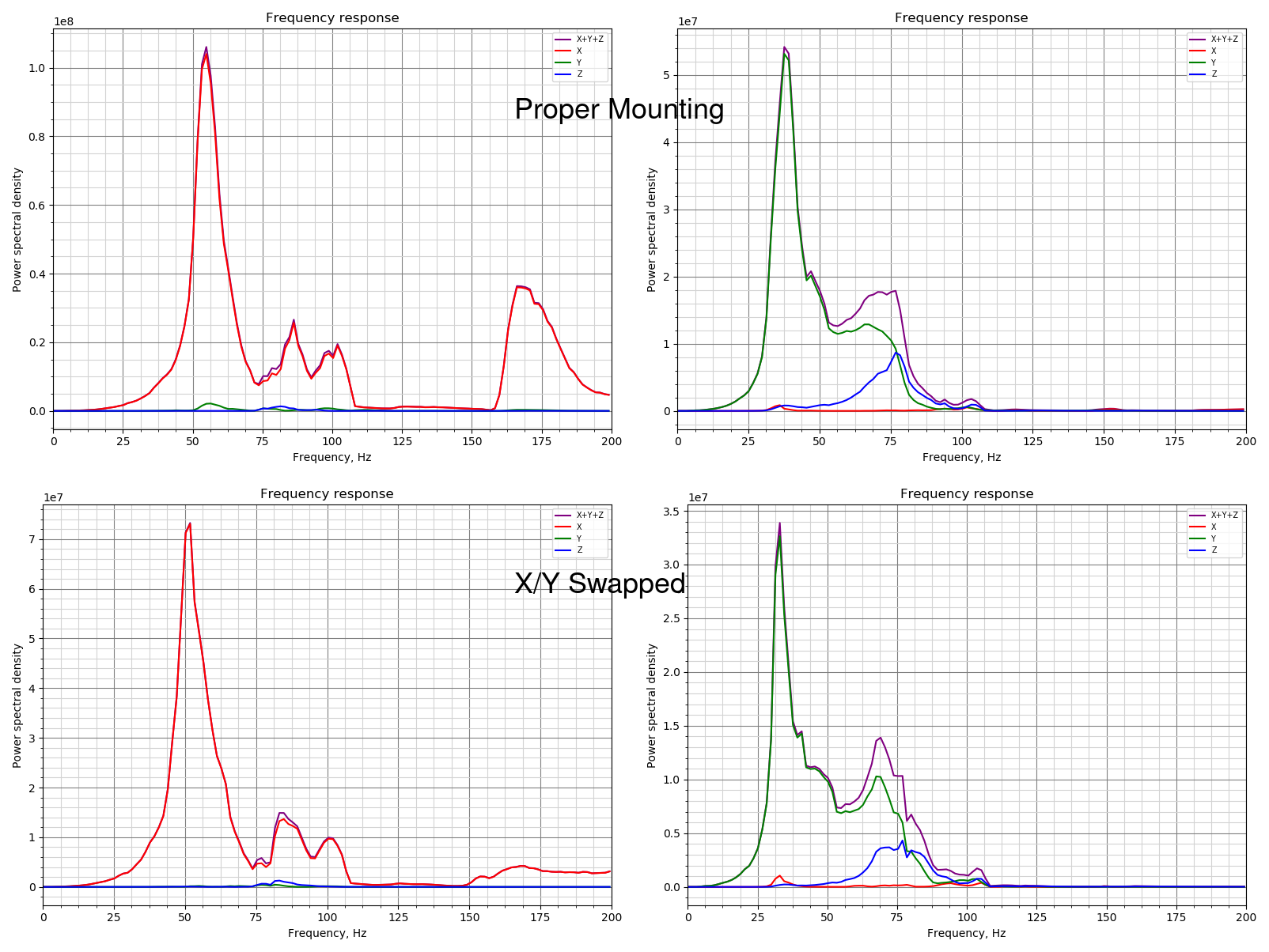
Good news is the shape of the curves are about the same. With the exception of the flattening of the resonant peak at 160hz in X and all of remaining peaks being a little lower in scale.
Said another way, would keeping the analysis and graphing as a separate tool in the Klipper repo be sufficient for the target users?
I'd agree with what @KevinOConnor is saying here. Having the graph output is great at this point in development to help build confidence in the tools, but I think as the feature matures more and more, the necessity of it drops and becomes more academic. At that point, pulling the raw data off of the device and end-user analysis happening off the Pi might make more sense.
That being said, it was nice to scp the raw data and the plots, for quick visual confirmation.
Matplotlib takes long enough to install that there will be a fairly large subset of the population that will think it failed (even with warning). I'd vote for leaving the functionality there, but optional. Honestly, though, it is not a strong preference either way. Though there is a risk of people misinterpreting the raw data.
I'm a big +1 for merging the feature, in general.
seth-cohen
on 22 Sep 2020
@seth-cohen Thanks!
One note - I think some of the Y/Z axes cross talk might be due to the adafruit breakout board design.
I tested this hypothesis by rotating the board and testing again. I have proved my hypothesis WRONG.
OK, that's good to know. Indeed, from the charts it does look like your printer has a resonance on Z axis at around 75 Hz (I'm not sure what kinematics do you have, but probably the vibrations of the Y axis around this frequency cause the bed or frame oscillations).
Good news is the shape of the curves are about the same. With the exception of the flattening of the resonant peak at 160hz in X and all of remaining peaks being a little lower in scale.
If you have updated the branch in the meanwhile, then that's to be expected: I committed a change to normalize (divide) the peaks by frequency. If you will sync now, you'd get also the Welch's algorithm, which will also change the amplitude due to averaging the frequency response over time.
I'm a big +1 for merging the feature, in general.
For the feature, we have the following options on the table:
- Only keep the code to run the test and record accelerometer readings in Klipper itself; let the user copy the raw accelerometer data from an RPi and run a script (on a host) that can suggest shapers and their frequency, plot the charts, etc. This is Kevin's suggestion, if I understood it correctly.
- Also add the functionality to calculate the frequency response and auto-tune the input shapers to Klipper; this does require an additional dependency - NumPy - to be installed. This will also require us to add and maintain the implementation of the Welch's algorithm to Klipper purely in NumPy (I've made an implementation but not committed it yet). Let the plotting be optional in Klipper and have a script that can do more advanced things with the raw accelerometer data (so if a user wants, they can generate and copy the raw data from their RPi to the host for a more advanced analysis, but this won't be necessary for some of the workflows). This is what I'd suggest.
- Keep the current (matplotlib-based) implementation of the frequency response calculation, and also support plotting in Klipper. This will require all users to install matplotlib on RPi. On the positive side, we won't have to maintain any numerical algorithms in Klipper.
dmbutyugin
on 22 Sep 2020
I think installing matplotlib takes this much time. I have a hope (but I should double-check) that installing just numpy should be noticeably faster.
FYI, I ran a test on my rpi3 (with octopi v0.17.0):
pi@octopi-delta:~ $ virtualenv -p python2 ~/test-env
Running virtualenv with interpreter /usr/bin/python2
New python executable in /home/pi/test-env/bin/python2
Also creating executable in /home/pi/test-env/bin/python
Installing setuptools, pkg_resources, pip, wheel...done.
pi@octopi-delta:~ $ time ~/test-env/bin/pip install numpy
DEPRECATION: Python 2.7 reached the end of its life on January 1st, 2020. Please upgrade your Python as Python 2.7 is no longer maintained. pip 21.0 will drop support for Python 2.7 in January 2021. More details about Python 2 support in pip can be found at https://pip.pypa.io/en/latest/development/release-process/#python-2-support pip 21.0 will remove support for this functionality.
Looking in indexes: https://pypi.org/simple, https://www.piwheels.org/simple
Collecting numpy
  Downloading numpy-1.16.6.zip (5.1 MB)
     |████████████████████████████████| 5.1 MB 87 kB/s
Building wheels for collected packages: numpy
  Building wheel for numpy (setup.py) ... done
  Created wheel for numpy: filename=numpy-1.16.6-cp27-cp27mu-linux_armv7l.whl size=10420455 sha256=2d0c5108a729c588e6d6dc657a9b7cbc76a27692c21990dcdf5bfb58cd6ac20e
  Stored in directory: /home/pi/.cache/pip/wheels/fe/49/d9/dbd8037d1f7b1672ebcdba0c75f1b7000d9e888a33af294c35
Successfully built numpy
Installing collected packages: numpy
Successfully installed numpy-1.16.6

real    9m8.727s
user    19m44.956s
sys     0m37.085s


md5-0aa6da75bccb5962c2f8a02b981b8af8


pi@octopi-delta:~ $ time ~/test-env/bin/pip install matplotlib
DEPRECATION: Python 2.7 reached the end of its life on January 1st, 2020. Please upgrade your Python as Python 2.7 is no longer maintained. pip 21.0 will drop support for Python 2.7 in January 2021. More details about Python 2 support in pip can be found at https://pip.pypa.io/en/latest/development/release-process/#python-2-support pip 21.0 will remove support for this functionality.
Looking in indexes: https://pypi.org/simple, https://www.piwheels.org/simple
Collecting matplotlib
  Downloading matplotlib-2.2.5.tar.gz (36.7 MB)
     |████████████████████████████████| 36.7 MB 15 kB/s
Requirement already satisfied: numpy>=1.7.1 in ./test-env/lib/python2.7/site-packages (from matplotlib) (1.16.6)
Collecting cycler>=0.10
  Downloading cycler-0.10.0-py2.py3-none-any.whl (6.5 kB)
Collecting pyparsing!=2.0.4,!=2.1.2,!=2.1.6,>=2.0.1
  Downloading pyparsing-2.4.7-py2.py3-none-any.whl (67 kB)
     |████████████████████████████████| 67 kB 894 kB/s
Collecting python-dateutil>=2.1
  Downloading python_dateutil-2.8.1-py2.py3-none-any.whl (227 kB)
     |████████████████████████████████| 227 kB 1.2 MB/s
Collecting pytz
  Downloading pytz-2020.1-py2.py3-none-any.whl (510 kB)
     |████████████████████████████████| 510 kB 1.1 MB/s
Collecting six>=1.10
  Downloading six-1.15.0-py2.py3-none-any.whl (10 kB)
Collecting kiwisolver>=1.0.1
  Downloading kiwisolver-1.1.0.tar.gz (30 kB)
Collecting backports.functools_lru_cache
  Downloading backports.functools_lru_cache-1.6.1-py2.py3-none-any.whl (5.7 kB)
Collecting subprocess32
  Downloading subprocess32-3.5.4.tar.gz (97 kB)
     |████████████████████████████████| 97 kB 734 kB/s
Requirement already satisfied: setuptools in ./test-env/lib/python2.7/site-packages (from kiwisolver>=1.0.1->matplotlib) (44.1.1)
Building wheels for collected packages: matplotlib, kiwisolver, subprocess32
  Building wheel for matplotlib (setup.py) ... done
  Created wheel for matplotlib: filename=matplotlib-2.2.5-cp27-cp27mu-linux_armv7l.whl size=11278781 sha256=513134f993c587c9569099d184df64e91d3d67571b20c96d4865f3a302f5c276
  Stored in directory: /home/pi/.cache/pip/wheels/20/af/9f/bca6e52dc48188e4068752906758846bd9dfeac4e480d24218
  Building wheel for kiwisolver (setup.py) ... done
  Created wheel for kiwisolver: filename=kiwisolver-1.1.0-cp27-cp27mu-linux_armv7l.whl size=1363896 sha256=2b74463f789f3ba98b1cf5c5d5c8716ada739ee96d86d190494dc0553b835b44
  Stored in directory: /home/pi/.cache/pip/wheels/80/b4/b8/99e51e2ccaadfdf828c133ca0e624cbb737a06ad343d112978
  Building wheel for subprocess32 (setup.py) ... done
  Created wheel for subprocess32: filename=subprocess32-3.5.4-cp27-cp27mu-linux_armv7l.whl size=52168 sha256=c10f0430f90c4f2ff225eebfd4fbc2d9bd7427791b4228a8215f5ed9d5b1c2c3
  Stored in directory: /home/pi/.cache/pip/wheels/e3/c7/6a/434fc8f2936acc4964ded8478435a8ef7c69eb41df7007a49f
Successfully built matplotlib kiwisolver subprocess32
Installing collected packages: six, cycler, pyparsing, python-dateutil, pytz, kiwisolver, backports.functools-lru-cache, subprocess32, matplotlib
Successfully installed backports.functools-lru-cache-1.6.1 cycler-0.10.0 kiwisolver-1.1.0 matplotlib-2.2.5 pyparsing-2.4.7 python-dateutil-2.8.1 pytz-2020.1 six-1.15.0 subprocess32-3.5.4

real    8m4.895s
user    7m3.587s
sys     0m22.728s
So, ~9 minutes for numpy and then ~8 minutes for matplotlib (without numpy). Matplotlib with numpy I expect would take ~17 minutes.
-Kevin
KevinOConnor
on 22 Sep 2020
For the feature, we have the following options on the table:
Only keep the code to run the test and record accelerometer readings in Klipper itself; let the user copy the raw accelerometer data from an RPi and run a script (on a host) that can suggest shapers and their frequency, plot the charts, etc. This is Kevin's suggestion, if I understood it correctly.
FWIW, I'd also document how to run the commands on the rpi itself (for those not wishing to install software on their desktop).
Separately, I think there is a "fourth option" - klippy could run an external program (via a system call) that performs the actual analysis. Thus, the matplotlib/numpy dependency is not in klippy (it would be a dependency in the "external" script). I'm not sure this offers any particular gains, but figured I'd mention it.
-Kevin
KevinOConnor
on 22 Sep 2020
Me thinks that matplotlib being a required dependency is too much to add. However, if there are other features that could benefit from it, I think that makes things a bit different.
however, I think having the suggested shapers (presumably numpy required) would be key functionality for the feature.
seth-cohen
on 22 Sep 2020
@KevinOConnor
So, ~9 minutes for numpy and then ~8 minutes for matplotlib (without numpy). Matplotlib with numpy I expect would take ~17 minutes.
That may not be sufficiently fast, I admit. However, I tried the following sequence:
$ virtualenv -p python2 ~/test-env
$ ~/test-env/bin/pip wheel -v numpy
$ ~/test-env/bin/pip install -v numpy
and then the installation finishes in less than a minute (i.e. by installing a precompiled numpy-1.16.6.zip package). I'm on
$ cat /etc/issue.net
Raspbian GNU/Linux 10
if that matters.
Edit: However, I wonder if it used some precompiled package from the previous installation attempt?
dmbutyugin
on 22 Sep 2020
Just my 2 cents:
- This feature is testified by all "beta testers" (including myself) as a real game changer in terms of print quality
- From my personal experience it means: Quieter and smoother run of the printer (I had some unused and loose M3 nuts in my print-head that would get excited by the vibration and the shaper audibly stopped them from rattling) and I'm also convinced that it adds in day to day print quality
- Besides intelligent stepper driver like the TMC, this feature is one of the very rare real advancements in our consumer/hobbyist/maker scene IMHO (except of course RGB led strips that change color on every line of processed gcode :stuck_out_tongue_winking_eye:)
- Yes it requires some tinkering with the printer but my wild guess is, that only very few of us just buy such a beast and are happy printing Lego bricks with the default settings
Having said the above:
- I'm definitively and absolutely in favor of having this in standard Klipper
- If it helps the installation concerns:
- Print a warning during install, that this could take up to 20 minutes on a Pi 3
- Only add the optimization, i.e.
SHAPER_CALIBRATEwithout graphical analysis as default and document how to add the matplotlib feature if someone wishes to use it - Have the analysis scripts return a meaningful error if some dependencies are not fulfilled
- Rather spend some time on installation and make the entry hurdle in using this feature as low as possible
Sorry for not contributing to the test currently, but I tore down my printer to add linear rails, which is more of a PITA than initially thought.
Sineos
on 22 Sep 2020
@KevinOConnor @dmbutyugin FWIW I found that I had to create a swap file to get numpy to install a little while ago (it was for a heat-bed map extension in Octoprint). My RPi3 was taking ages and eventually timing out. Adding a 1G swap file sorted out the problem and made it install pretty fast.
 theopensourcerer
on 22 Sep 2020
theopensourcerer
on 22 Sep 2020
Edit: However, I wonder if it used some precompiled package from the previous installation attempt?
Unfortunately, that seems to be the way. After deleting a precompiled wheel package from the cache,
$ ~/test-env/bin/pip wheel --only-binary :all: -v numpy
fails with an error DistributionNotFound: No matching distribution found for numpy. Interestingly,
$ virtualenv -p python3 ~/test-env3
$ time ~/test-env3/bin/pip wheel  --only-binary :all: -v numpy
$ time ~/test-env3/bin/pip install  --only-binary :all: -v numpy
succeeds. So I understand that the support of Python2 was dropped from the precompiled wheels. Whenever Klipper (eventually?) migrates to Python 3, fast installation of NumPy should no longer be a problem.
As a compromise, I can propose to run the installation with -v key, which at least dumps the compilation log to the console - so the users won't think the installation got stuck. And we can put the 'Software installation' section prior to 'HW installation' with a comment that one can start the numpy installation and solder the accelerometer and crimp the connectors in the meanwhile - that will certainly take more than ~10 minutes.
@KevinOConnor @dmbutyugin FWIW I found that I had to create a swap file to get numpy to install a little while ago (it was for a heat-bed map extension in Octoprint). My RPi3 was taking ages and eventually timing out. Adding a 1G swap file sorted out the problem and made it install pretty fast.
@theopensourcerer how much RAM do you have on your RPi3? I guess whether you'll need swap or not depends on that.
Separately, I think there is a "fourth option" - klippy could run an external program (via a system call) that performs the actual analysis.
@KevinOConnor That is an option, but I would rather avoid it: it would make X-process interfacing more complicated (right now the code relies on multiprocess 'fork' essentially, making all raw data available to the child process without extra efforts). And I suppose there is a reason to have a virtual environment in the first place? That Klipper itself does not rely on the packages provided in the repo.
dmbutyugin
on 22 Sep 2020
As a compromise, I can propose to run the installation with -v key, which at least dumps the compilation log to the console - so the users won't think the installation got stuck.
FWIW, if we add this to klippy then I think the additional dependencies should be added to scripts/install-octopi.sh (and similar). We'd want that to improve overall test coverage and to keep the klippy regression tests sane. However, I can't see having every user take ~10 additional minutes on a new install for a feature few users would use.
One solution would be to switch klippy to python3, but I think the reality is that is unlikely to occur in 2020. So, I'd say going that approach would delay merging for several months.
-Kevin
KevinOConnor
on 23 Sep 2020
@theopensourcerer how much RAM do you have on your RPi3? I guess whether you'll need swap or not depends on that.
@dmbutyugin My RPi3 is a B+ which has 1G. I also have an RPi3 A+ which has 512M. Both perform perfectly well once setup. It was only when Python was trying to "build(?)" numpy that it failed. I just thought it might be useful info that a swap file helped alleviate the problem.
FWIW I am now running mainsail/moonraker.
theopensourcerer
on 23 Sep 2020
@KevinOConnor
However, I can't see having every user take ~10 additional minutes on a new install for a feature few users would use.
I totally agree with this point.
FWIW, if we add this to klippy then I think the additional dependencies should be added to scripts/install-octopi.sh (and similar).
Sorry, I am not sure I fully understand why this is really necessary - i.e. why cannot only the users that really use this functionality be asked to install an extra dependency? And in light of
We'd want that to improve overall test coverage and to keep the klippy regression tests sane.
How would this be different if we make Klippy call a separate script - that script would also need that dependency (installed either viapip or apt etc.)? And given that the current code loads numpy and matplotlib dynamically using importlib, it is trivial to make a code only load numpy when the required functionality is requested (i.e. user wants Klipper to calculate the frequency response and maybe auto-tune input shaper). So in regression test it would be possible to call, for instance, a sequence
TEST_RESONANCES AXIS=X
ACCELEROMETER_MEASURE
that wouldn't invoke that functionality, and that particular test wouldn't need numpy to be installed. Of course, if a regtest will test, say, input shaper auto-tuning, then numpy will have to be installed either way. And dynamic loading of the libraries makes it possible to generate a meaningful error response to the user suggesting to follow the instructions and install the missing dependencies (instead of producing less informative crash dump in the logs).
One solution would be to switch klippy to python3, but I think the reality is that is unlikely to occur in 2020. So, I'd say going that approach would delay merging for several months.
I understand this, I meant it more like: we may accept some nuisance (longer numpy install) for users who want to use this new feature now, given that in the future the situation will improve (so it is not a permanent nuisance). And maybe at this point it would make sense to add numpy to scripts/install-octopi.sh and such?
FWIW, there is a fifth alternative - implement FFT ourselves - but I'd really prefer not to go that route.
dmbutyugin
on 24 Sep 2020
FWIW, if we add this to klippy then I think the additional dependencies should be added to scripts/install-octopi.sh (and similar).
Sorry, I am not sure I fully understand why this is really necessary - i.e. why cannot only the users that really use this functionality be asked to install an extra dependency?
Ah, I think I misunderstood your proposal. I guess you want to document a requirement for users to run a separate script (and/or commands) to install the dependencies? I guess we could do that. It would not allow us to add klippy regression tests for resonance_tester - but that may not make sense anyway.
FWIW, though, if the user has to ssh into the rpi and run an additional install script, I'm not sure how much of an advantage that is over running an additional analysis script..
How would this be different if we make Klippy call a separate script - that script would also need that dependency (installed either viapip or apt etc.)?
Well, in that case, the install-octopi.sh command could install the dependences using the system installer - which installs in seconds. (The analysis tool could also use python3.) That is, an external script does not need to use the klippy-env setup. As before though, I'm not sure calling an external script from klippy is a good plan.
FWIW, there is a fifth alternative - implement FFT ourselves - but I'd really prefer not to go that route.
Eeks! I'd also prefer not to go that route.
For the feature, we have the following options on the table:
Just to state it outright, the option to "generate movement / capture data in klippy and graph / analyze from command-line tool" is a better fit for my workflow. Thus it is my preferred option. However, if you prefer to do the analysis from Klippy then I'm okay with that. In that case it seems we can't install the dependencies from install-octopi.sh, but it sounds like you've got an alternative for that.
Cheers,
-Kevin
KevinOConnor
on 24 Sep 2020
@KevinOConnor
Ah, I think I misunderstood your proposal. I guess you want to document a requirement for users to run a separate script (and/or commands) to install the dependencies? I guess we could do that.
Yes, that's actually my proposal.
FWIW, though, if the user has to ssh into the rpi and run an additional install script, I'm not sure how much of an advantage that is over running an additional analysis script..
Well, installation is done once, and ssh'ing to either copy the data, or running a stand-alone script will have to be done every time the input shaper calibration is needed. FWIW, I do not expect it to happen often, but still it will be more convenient in my opinion (for some users, at least).
Just to state it outright, the option to "generate movement / capture data in klippy and graph / analyze from command-line tool" is a better fit for my workflow. Thus it is my preferred option. However, if you prefer to do the analysis from Klippy then I'm okay with that. In that case it seems we can't install the dependencies from install-octopi.sh, but it sounds like you've got an alternative for that.
I think it would make sense to have a stand-alone script too. In my view, there are 2 possible flows:
Just run
SHAPER_CALIBRATE [AXIS=...]followed bySAVE_CONFIG. This is what many likely will be doing normally.Run something like
TEST_RESONANCES AXIS=... [RAW_NAME=raw-data-test-abc...-attempt-3.csv], then copy the data to the host for future processing. Then one can runscripts/graph_accelerometer.pywith the appropriate parameters, orscripts/calibrate_shaper.py.
BTW, I updated the code in my adxl345-spi branch to use its own Welch's algorithm implementation (it turned out to be not too bad), and to only load numpy and matplotlib when the respective functionality is necessary. And made a stand-alone calibrate_shaper.py script, as well as pulled graph_accelerometer.py script from your branch with some minor updates (mostly to avoid code duplication).
Now, I think code-wise the feature is mostly ready (just maybe add better error messages if one of those is not installed), as well as the documentation (I'd clarify the recommendation to install numpy only). Maybe if there are no major concerns, I can start slowly sending some pull requests to integrate this functionality into the mainline Klipper.
dmbutyugin
on 25 Sep 2020
The main resonance testing algorithm was integrated into mainline Klipper (#3381). Today I pushed an enhancement for the automatic shaper calibration algorithm to adxl345-spi branch (15d5662b99b53e5695d8734810386c49acb1cc27): to account shaper smoothing. The smoothing is computed approximately for the commanded trajectory, and is both reported and used to choose the 'best' input shaper configuration, e.g.
Fitted shaper 'zv' frequency = 31.2 Hz (vibrations = 31.9%, smoothing ~= 0.158)
Fitted shaper 'mzv' frequency = 31.0 Hz (vibrations = 13.3%, smoothing ~= 0.212)
Fitted shaper 'ei' frequency = 37.6 Hz (vibrations = 15.7%, smoothing ~= 0.228)
Fitted shaper '2hump_ei' frequency = 40.9 Hz (vibrations = 7.9%, smoothing ~= 0.323)
Fitted shaper '3hump_ei' frequency = 46.0 Hz (vibrations = 5.5%, smoothing ~= 0.387)
Recommended shaper is 3hump_ei @ 46.0 Hz
The reported values are approximate, and are not to be taken directly, but they offer a reasonably fair comparison of the different input shaper configurations in terms of smoothing. They also another advanced feature: one can specify a maximum allowed smoothing, and the code will try to find the best shaper configuration accounting that limit, e.g.:
SHAPER_CALIBRATE ... MAX_SMOOTHING=0.15
or
$ python scripts/calibrate_shaper.py raw_data...csv --max_smoothing=0.15
This can be used, for example, if the user is not happy with excessive smoothing the input shaper produces; then knowing the value from the original tuning attempt they can set max smoothing value e.g. 1.5 - 2x smaller, and see if the smoothing improves (at the expense of some increase of the ringing). E.g. in that example above, if we set --max_smoothing=0.3, we can get:
Fitted shaper 'zv' frequency = 31.2 Hz (vibrations = 31.9%, smoothing ~= 0.158)
Fitted shaper 'mzv' frequency = 31.0 Hz (vibrations = 13.3%, smoothing ~= 0.212)
Fitted shaper 'ei' frequency = 37.6 Hz (vibrations = 15.7%, smoothing ~= 0.228)
Fitted shaper '2hump_ei' frequency = 42.5 Hz (vibrations = 8.0%, smoothing ~= 0.299)
Fitted shaper '3hump_ei' frequency = 52.4 Hz (vibrations = 6.5%, smoothing ~= 0.298)
Recommended shaper is 3hump_ei @ 52.4 Hz
Overall, I tried this new code on the raw test results I had available, and I am pretty happy with the results. But it would be great to get a bit more testing of this feature, before trying to make a PR. So if you could give it a try, that would be great. @Sineos , @jdlongenecker , @BlackStump, @seth-cohen you previously made the tests with the accelerometer, so maybe it wouldn't be a lot of efforts to re-run the tests with a new code?
dmbutyugin
on 16 Oct 2020
This is really a useful addition:
pi@octopi ~/klipper $ python scripts/calibrate_shaper.py /tmp/raw_data_x_20201017_082857.csv -o calibration_x.png
Fitted shaper 'zv' frequency = 41.2 Hz (vibrations = 40.4%, smoothing ~= 0.095)
Fitted shaper 'mzv' frequency = 28.4 Hz (vibrations = 21.8%, smoothing ~= 0.253)
Fitted shaper 'ei' frequency = 38.8 Hz (vibrations = 21.1%, smoothing ~= 0.214)
Fitted shaper '2hump_ei' frequency = 37.5 Hz (vibrations = 12.3%, smoothing ~= 0.384)
Fitted shaper '3hump_ei' frequency = 46.0 Hz (vibrations = 9.3%, smoothing ~= 0.387)
Recommended shaper is 3hump_ei @ 46.0 Hz
pi@octopi ~/klipper $ python scripts/calibrate_shaper.py /tmp/raw_data_x_20201017_082857.csv -o calibration_x_max15.png --max_smoothing=0.15
Fitted shaper 'zv' frequency = 41.2 Hz (vibrations = 40.4%, smoothing ~= 0.095)
Fitted shaper 'mzv' frequency = 37.0 Hz (vibrations = 24.1%, smoothing ~= 0.149)
Fitted shaper 'ei' frequency = 46.4 Hz (vibrations = 22.7%, smoothing ~= 0.150)
Fitted shaper '2hump_ei' frequency = 60.1 Hz (vibrations = 17.1%, smoothing ~= 0.149)
Fitted shaper '3hump_ei' frequency = 74.0 Hz (vibrations = 14.2%, smoothing ~= 0.150)
Recommended shaper is 3hump_ei @ 74.0 Hz
pi@octopi ~/klipper $ python scripts/calibrate_shaper.py /tmp/raw_data_x_20201017_082857.csv -o calibration_x_max1.png --max_smoothing=0.1
Fitted shaper 'zv' frequency = 41.2 Hz (vibrations = 40.4%, smoothing ~= 0.095)
Fitted shaper 'mzv' frequency = 45.2 Hz (vibrations = 26.5%, smoothing ~= 0.100)
Fitted shaper 'ei' frequency = 56.8 Hz (vibrations = 26.6%, smoothing ~= 0.100)
Fitted shaper '2hump_ei' frequency = 73.5 Hz (vibrations = 21.4%, smoothing ~= 0.100)
Fitted shaper '3hump_ei' frequency = 90.6 Hz (vibrations = 19.1%, smoothing ~= 0.100)
Recommended shaper is 3hump_ei @ 90.6 Hz

pi@octopi ~/klipper $ python scripts/calibrate_shaper.py /tmp/raw_data_y_20201017_084005.csv -o calibration_y_default.png
Fitted shaper 'zv' frequency = 56.8 Hz (vibrations = 31.1%, smoothing ~= 0.054)
Fitted shaper 'mzv' frequency = 51.8 Hz (vibrations = 16.1%, smoothing ~= 0.076)
Fitted shaper 'ei' frequency = 63.0 Hz (vibrations = 15.8%, smoothing ~= 0.081)
Fitted shaper '2hump_ei' frequency = 64.5 Hz (vibrations = 9.2%, smoothing ~= 0.130)
Fitted shaper '3hump_ei' frequency = 69.0 Hz (vibrations = 5.8%, smoothing ~= 0.172)
Recommended shaper is 3hump_ei @ 69.0 Hz
pi@octopi ~/klipper $ python scripts/calibrate_shaper.py /tmp/raw_data_y_20201017_084005.csv -o calibration_y_max15.png --max_smoothing=0.15
Fitted shaper 'zv' frequency = 56.8 Hz (vibrations = 31.1%, smoothing ~= 0.054)
Fitted shaper 'mzv' frequency = 51.8 Hz (vibrations = 16.1%, smoothing ~= 0.076)
Fitted shaper 'ei' frequency = 63.0 Hz (vibrations = 15.8%, smoothing ~= 0.081)
Fitted shaper '2hump_ei' frequency = 64.5 Hz (vibrations = 9.2%, smoothing ~= 0.130)
Fitted shaper '3hump_ei' frequency = 74.0 Hz (vibrations = 6.3%, smoothing ~= 0.150)
Recommended shaper is 3hump_ei @ 74.0 Hz
pi@octopi ~/klipper $ python scripts/calibrate_shaper.py /tmp/raw_data_y_20201017_084005.csv -o calibration_y_max1.png --max_smoothing=0.1
Fitted shaper 'zv' frequency = 56.8 Hz (vibrations = 31.1%, smoothing ~= 0.054)
Fitted shaper 'mzv' frequency = 51.8 Hz (vibrations = 16.1%, smoothing ~= 0.076)
Fitted shaper 'ei' frequency = 63.0 Hz (vibrations = 15.8%, smoothing ~= 0.081)
Fitted shaper '2hump_ei' frequency = 73.5 Hz (vibrations = 10.1%, smoothing ~= 0.100)
Fitted shaper '3hump_ei' frequency = 90.6 Hz (vibrations = 9.4%, smoothing ~= 0.100)
Recommended shaper is 3hump_ei @ 90.6 Hz
Especially information like this (X-Axis / default vs. max 0.15):
Fitted shaper '3hump_ei' frequency = 46.0 Hz (vibrations = 9.3%, smoothing ~= 0.387)
Fitted shaper '3hump_ei' frequency = 74.0 Hz (vibrations = 14.2%, smoothing ~= 0.150)
So 5% more reduction in vibration but factor 2.6 in smoothing. In such cases I'd rather choose the smaller smoothing.
Now it would be really cool to have the algorithm find the "sweet spot" (max vibration reduction with least smoothing) automatically and maybe output the top 3 scenarios.
Thanks for keeping it up.
Attached:
- raw data
- klippy.log
- png's
Sineos
on 17 Oct 2020
Hello,
I must have missed something but imposible to have a working adl345 with klipper... I first tried with a custom armbian installed on OrangePI PC 2 (cheaper and faster than a RPI3, GPIO pin compatible). Double / triple and even more checked the wirering, changed the cables and the sensor. No way: always an error while reading the answers from the sensor. Required /dev device is present.
Klipper is working fine without the adl345 sensor settings. I applied the settings specified in the resonnance compensation document.
I also tried a RPI3 (not on OctoPI distribution, I tried with a custom alpine 64 bits, /dev related device also present).
Possible it's an 64 bit issue (all test were done on 64 bits kernels)? Some older kernel required to work (tried kernels >= 5.4.x)? Other cause you could see?
Philippe
 opensource-alt
on 21 Oct 2020
opensource-alt
on 21 Oct 2020
Hello,
After some tests:
- not related to power issues (checked there's no power issues with dmesg, also tried a 4V LIPO battery to power the ADXL345 board)
- spidev ioctl access is working on a 32 bits kernel (OctoPI with latest kernel) but inconsitent results obtained with ACCELEROMETER_QUERY (most of the time: the expected 0xE5 is not received).
- same sdcard used on a rPI 2 powered with the same switching regualtor than the non working rPI 3 above : works out of the box.
Sounds like https://stackoverflow.com/questions/48321492/adxl345-device-id-and-offset-being-wrong-raspberry-pi
Maybe a sync issue on some hardware.
Philippe
opensource-alt
on 24 Oct 2020
I must have missed something but imposible to have a working adl345 with klipper... I first tried with a custom armbian installed on OrangePI PC 2 (cheaper and faster than a RPI3, GPIO pin compatible). Double / triple and even more checked the wirering, changed the cables and the sensor. No way: always an error while reading the answers from the sensor. Required /dev device is present.
Did you check SPI with a local loopback cable from linux command line?
 1N4148
on 24 Oct 2020
1N4148
on 24 Oct 2020
Well, no. I Saw the loopback test wasn't working and I didn't know why until now and after reading this https://forum.armbian.com/topic/10066-some-problem-about-opi-pc2-spi-connect-mfrc522/
So: not so pin compatible as spi0 is spi1 here...
Still the same error when querying the sensor: unable to obtain spi_transfert_response. The root cause in an issue calling io to function. Error 14, bad address.
Correct spidev1.0 was opened by klipper_mcu daemon (checked with strace)
No idea why the 64 bit rPI3 kernel wasn't working as I overwrited since the custom SD card.
I'll keep the rPI 3 (32 bits kernel) for the prints and the rPI 2 for the calibration for now.
Philippe
opensource-alt
on 24 Oct 2020
@opensource-alt So, the same (32-bit) installation works on RPi 2, but does not work on RPi 3? And didn't work on 64 bit installation on the Orange Pi either? Well, @KevinOConnor wrote the low-level communication interface to ADXL345 (as well as Klipper SPI communication). In general, we'd need the full klippy.log of the failed attempt (and the result from the Octoprint console).
As a separate wild guess, you could check that your cable is not too long. I had problems when I made too long cable myself (granted, there could've been other issues with that cable of mine). But I do suspect that long cable can get noticeably high inductivity and capacitance, potentially influencing the step signal shape, and also becoming more susceptible to picking up noise.
dmbutyugin
on 25 Oct 2020
Opinion about numpy:
Most people switching to klipper right now are those who have experience in printing and are aware of linux requirements. Klipper is not yet at the stage for just anyone to download, (silent) install, and have it just work. So asking people to install numpy is not a dealbreaker. Also, numpy is installed with the Bed Visualizer plug-in to Octoprint.
The-Monkey-King
on 25 Oct 2020
@dmbutyugin Thanks for your answer. I guess this issue should not be discussed here. I opened another thread.
opensource-alt
on 25 Oct 2020
@The-Monkey-King Thanks for the feedback. Actually, the automatic resonance testing code was accepted into the mainline Klipper by Kevin with this extra optional 'numpy' dependency. The extra installation is explained in the docs.
dmbutyugin
on 25 Oct 2020
@dmbutyugin I run the "ACCELEROMETER_QUERY" on klipper 0.9 head, giving me "adxl345 values (x, y, z): 0.000000, 0.000000, 0.000000".
Is my adxl345 broken?
I followed the instructions from (https://github.com/KevinOConnor/klipper/blob/master/docs/Measuring_Resonances.md) and also checked readout with removed wiring between raspi and adcl, resulting in: "Invalid adxl345 id (got 0 vs e5)".
klippy.log
 kookaburra88
on 28 Oct 2020
kookaburra88
on 28 Oct 2020
@kookaburra88 Unfortunately, it may be the case. The accelerometer should always give non-zero readings, because it should sense at least the earth gravity. You can give MEASURE_AXES_NOISE command a try, because it will try to measure the data for longer period of time. You can also try to double-check the wiring (that cable isn't loose in the connector or broken), but given that adxl345 id (e5) is successfully read, I think it is unlikely the problem. Which board did you get, BTW?
dmbutyugin
on 28 Oct 2020
@dmbutyugin I replaced the ADXL345 with a new one. Now it is working. Thanks a lot for your help and the contribution.
kookaburra88
on 29 Oct 2020
@dmbutyugin I tried your branch that mentions and can target the smoothing on my system. It's great! :+1:
Due to it being basically a "fixed up" Anet A8 (so Z-frame is still acrylic and wobbly) it benefited a LOT from the input shaping.
With the code that's in Klipper 0.9.1, it already had a huge improvement, but with the smoothing reporting and ability to set a target smoothing to try and find better matches allowed me to very easily tune it up and get acceptable vibration dampening and much improved smoothing. Basically a 3000mm/s² acceleration print now is comparable to a previous 1500mm/s².
This was done on a ADXL345 connected up to a RPi using the instructions of the main help.
I settled on aiming for below 0.25 smoothing as the default algorithm would end up choosing ~0.39 smoothing, and that is very definitely too high.
For interest sake, the settings I went with:
Y: Fitted shaper 'ei' frequency = 38.4 Hz (vibrations = 7.7%, smoothing ~= 0.218)
X: Fitted shaper '2hump_ei' frequency = 46.5 Hz (vibrations = 23.2%, smoothing ~= 0.250)
The unrestrained recommendation was:
Y: Fitted shaper '3hump_ei' frequency = 46.0 Hz (vibrations = 4.1%, smoothing ~= 0.387)
X: Fitted shaper '3hump_ei' frequency = 46.0 Hz (vibrations = 15.6%, smoothing ~= 0.387)
The original recommendation was (and settings I was using):
Y: Fitted shaper '2hump_ei' frequency = 37.5 Hz (vibrations = 4.6%)
X: Fitted shaper 'mzv' frequency = 25.0 Hz (vibrations = 22.7%)
I consider the new settings superior as it was smoothing very obviously at 1500mm/s² acceleration before.
(edited to clarify unrestrained/original recommendations)
 grigi
on 18 Nov 2020
grigi
on 18 Nov 2020
@grigi
The original recommendation was (and settings I was using):
Y: Fitted shaper '2hump_ei' frequency = 37.5 Hz (vibrations = 4.6%)
X: Fitted shaper 'mzv' frequency = 25.0 Hz (vibrations = 22.7%)
The original, you mean from Klipper 0.9.1 with ADXL345? TBH, the original X axis recommendation seems odd. Generally, the level of remaining X axis vibrations seems very large. Would you mind running a test again (either on Klipper 0.9.1 or on my branch, doesn't matter) with TEST_RESONANCES AXIS=X OUTPUT=raw_data and post an archived raw accelerometer data? I would like to take a look at it. You can also post Y axis results for completeness.
Edit: just please do not forget to disable input shaping and scurve before running the test again with SET_INPUT_SHAPER SHAPER_FREQ_X=0 SHAPER_FREQ_Y=0 and SET_SCURVE ACCEL_ORDER=2 MIN_ACCEL=7000 (and increase max_accel in printer.cfg as suggested by the guide).
dmbutyugin
on 19 Nov 2020
@dmbutyugin Here is the data (collected using your adxl345-spi branch):
calibration.zip
Yes, by original I mean Klipper 0.9.1 with ADXL345.
Looking at the results manually now, I see that it may be a magnitude issue?
e.g. zv(Y, 36.6) ~same magnitude of vibrations than undampened X.
Maybe it would be useful to also report the max vibration magnitude?
Because (if I multiply the damping ratio to the vibration) I get:
max(ei(Y, 38.4))~= 900max(zv(X, 28.6))~= 650
Compared to unrestrained recommendation:
max(3hump_ei(Y, 46.0))~= 850max(3hump_ei(X, 46.0))~= 400
The top one should give significantly less smoothing, and marginally worse ringing?
grigi
on 20 Nov 2020
how did you get the smoothing to show ? i believe i am latest commit i am checking again now but def not more than 2 weeks old
 robthide37
on 22 Nov 2020
robthide37
on 22 Nov 2020
how did you get the smoothing to show ? i believe i am latest commit i am checking again now but def not more than 2 weeks old
See https://github.com/KevinOConnor/klipper/issues/3027#issuecomment-710475887
Sineos
on 22 Nov 2020
Edit: just please do not forget to disable input shaping and scurve before running the test again with
SET_INPUT_SHAPER SHAPER_FREQ_X=0 SHAPER_FREQ_Y=0andSET_SCURVE ACCEL_ORDER=2 MIN_ACCEL=7000(and increasemax_accelin printer.cfg as suggested by the guide).
Yes, I think that was my mistake, I re-ran the collection of data with that recommendation and now getting more sensible results:
 $ scripts/calibrate_shaper.py raw_data_x_20201120_192349.csv
Fitted shaper 'zv' frequency = 31.0 Hz (vibrations = 36.0%, smoothing ~= 0.160)
Fitted shaper 'mzv' frequency = 23.0 Hz (vibrations = 21.9%, smoothing ~= 0.385)
Fitted shaper 'ei' frequency = 30.2 Hz (vibrations = 19.2%, smoothing ~= 0.353)
Fitted shaper '2hump_ei' frequency = 37.5 Hz (vibrations = 14.4%, smoothing ~= 0.384)
Fitted shaper '3hump_ei' frequency = 58.2 Hz (vibrations = 12.6%, smoothing ~= 0.242)
Recommended shaper is 3hump_ei @ 58.2 Hz

$ scripts/calibrate_shaper.py raw_data_y_20201120_193733.csv
Fitted shaper 'zv' frequency = 37.0 Hz (vibrations = 24.5%, smoothing ~= 0.115)
Fitted shaper 'mzv' frequency = 25.6 Hz (vibrations = 13.8%, smoothing ~= 0.311)
Fitted shaper 'ei' frequency = 35.4 Hz (vibrations = 10.1%, smoothing ~= 0.257)
Fitted shaper '2hump_ei' frequency = 37.5 Hz (vibrations = 5.6%, smoothing ~= 0.384)
Fitted shaper '3hump_ei' frequency = 64.8 Hz (vibrations = 5.8%, smoothing ~= 0.195)
Recommended shaper is 3hump_ei @ 64.8 Hz
Due to the magnitude of vibrations being so much less in X-axis, I went with the zv recommendation there, and ended up with still less vibrations than Y-axis with 3hump_ei. Also now enabling [scurve] on your scurve-shaping branch made for a really good print quality. I can literally cut anything from 20-50% of print time with these for the same print quality. Thank you for that!
grigi
on 22 Nov 2020
Would it be possible to add the console output "Fitted shaper ..." as well as the names of the input csv files at the bottom of the output diagram? Would make documentation and archiving of the results a litte bit easier, especially when modifiying the printer between measurements.
1N4148
on 27 Nov 2020
@1N4148 Could you be a bit more specific? You mean the diagram produced by calibrate_shaper.py script? BTW, it does mention the Hz parameter of the input shapers, but after adding vibrations and smoothing might be too much visual clutter?
dmbutyugin
on 1 Dec 2020
@grigi Could you share your raw_data_x_20201120_192349.csv and raw_data_y_20201120_193733.csv files?
dmbutyugin
on 1 Dec 2020
@dmbutyugin Sure, here is the archive:
raw_data_anet1.5.zip
The latter raw_data samples was the difference after replacing the Anet board 1.5 with an SKR Mini E3 2.0.
The trinamic drivers had remarkably different resonance frequencies. I think it is less though, but a much larger resonance band. I did not change anything on the frame/belts, so didn't expect this change. Just a surprising tidbit for you:
raw_data_skr_mini2.0.zip
grigi
on 1 Dec 2020
@grigi @Sineos @KevinOConnor
I pushed a bit updated version of the algorithm, which may account for smoothing a bit better, and may now choose a shaper configuration that is less aggressive in smoothing. I'd encourage everyone to try it now from adxl345-spi branch. Also, --max_smoothing= parameter to calibrate_shaper.py still works. If the algorithm works well for everyone, and if you see max_smoothing as being a useful addition, I'll make it configurable via [resonance_tester] section and as a parameter to SHAPER_CALIBRATE command in Klipper, update the docs and make a PR with it.
@1N4148 I also tried to add more information to the generated charts per your request to the branch (for now). Is this what you had in mind?
@Sineos
This is really a useful addition:
...
Especially information like this (X-Axis / default vs. max 0.15):Fitted shaper '3hump_ei' frequency = 46.0 Hz (vibrations = 9.3%, smoothing ~= 0.387) Fitted shaper '3hump_ei' frequency = 74.0 Hz (vibrations = 14.2%, smoothing ~= 0.150)So 5% more reduction in vibration but factor 2.6 in smoothing. In such cases I'd rather choose the smaller smoothing.
Now it would be really cool to have the algorithm find the "sweet spot" (max vibration reduction with least smoothing) automatically and maybe output the top 3 scenarios.
Note that in that your case it is not just '5% reduction' of vibrations, but rather 5 percentage points, so 35% reduction in this case. Though the updated algorithm now recommends
Fitted shaper '3hump_ei' frequency = 57.2 Hz (vibrations = 10.7%, smoothing ~= 0.250)
which is a bit more robust and a better 'all-round' value.
Overall, the problem is that different people may prefer to have either less smoothing or less vibrations, so finding a "sweet spot" that would work for everyone isn't that easy.
@grigi
Thanks!
The trinamic drivers had remarkably different resonance frequencies. I think it is less though, but a much larger resonance band.
Are you running them in stealchop mode? I see that the resonances are 'less strong', and also higher-frequency resonances are much smaller.
dmbutyugin
on 6 Dec 2020
Great, I'll test it the next days. Without --max-smoothing it recommended 3hump_ei which resulted in those gaps between infill and holes. With a conservative --max-smoothing of 0.150 the recommendation changed to 2hump_ei with the same frequency. No more gaps.
1N4148
on 6 Dec 2020
@dmbutyugin Thanks. I tested the updated script and I like the suggestions it makes. Every suggestion is better tuned than before. Nice :+1:
There is some minor confusion for me about the different shapers. The docs talk about how ei-shapers smooth much more than mzv or zv, shapers, and 2/3-hump smooth even more. But your models show that 3-hump ei shapers often do less smoothing.
And often mzv has a wider band of smoothing in the graphs than ei, but the docs say ei works over a wider band.
Is it just me mis-reading the graphs? or is it a modelling issue?
Also, yes, the trinamic drivers are run in stealthchop mode. I know it may have less torque but my frame can't move fast enough to need that torque.
grigi
on 6 Dec 2020
Looks good, maybe it would be better to swap the position of both legends?
Results on measurements on Ender 3:
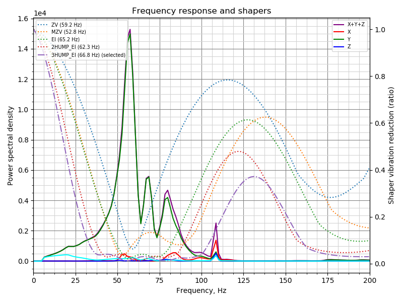
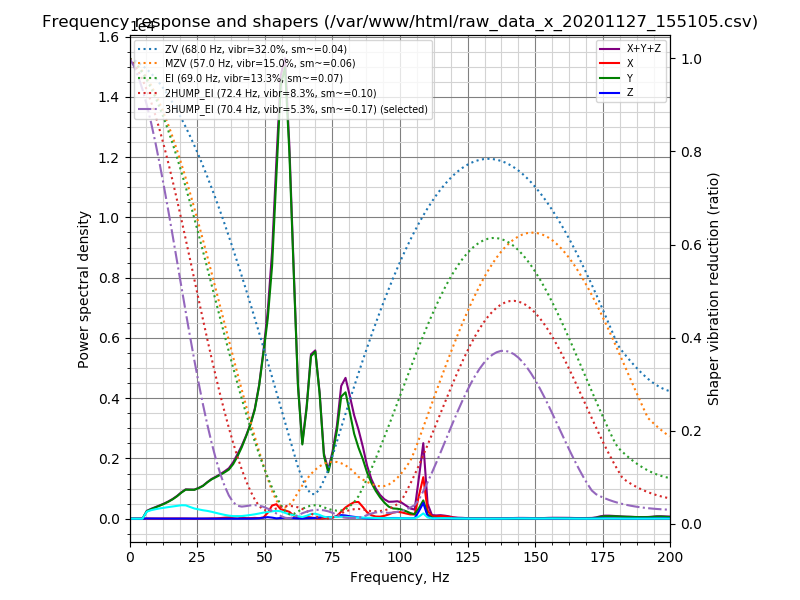
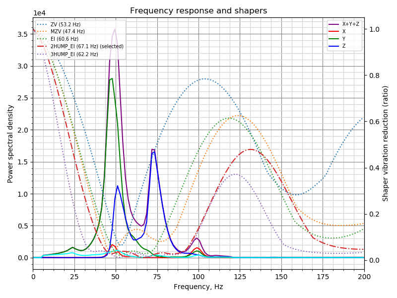
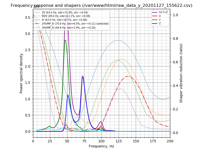
On Ender 5:
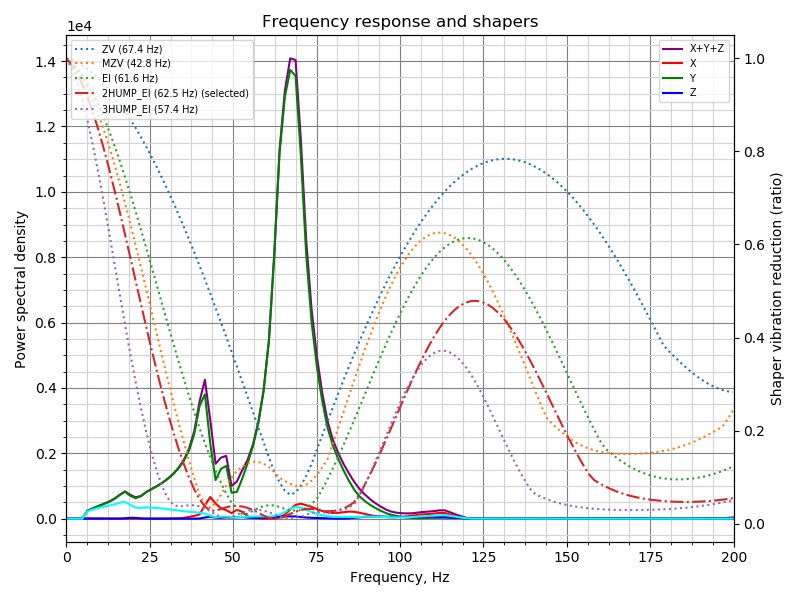
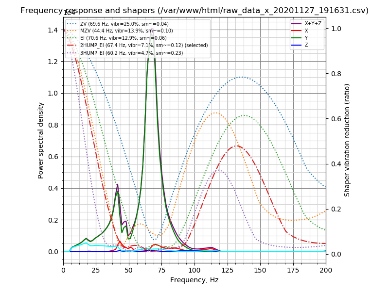
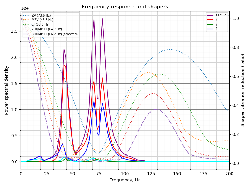
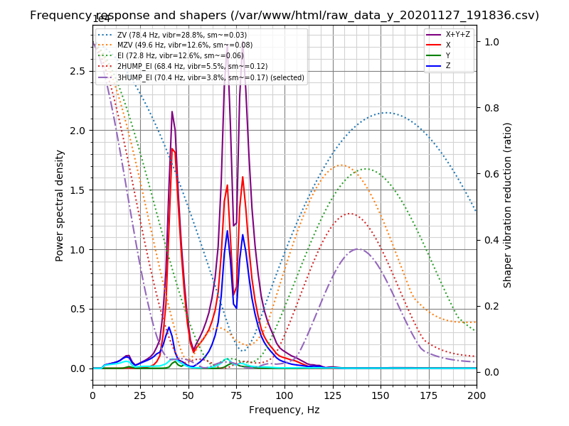
1N4148
on 6 Dec 2020
@grigi
There is some minor confusion for me about the different shapers. The docs talk about how ei-shapers smooth much more than mzv or zv, shapers, and 2/3-hump smooth even more. But your models show that 3-hump ei shapers often do less smoothing.
And often mzv has a wider band of smoothing in the graphs than ei, but the docs say ei works over a wider band.Is it just me mis-reading the graphs? or is it a modelling issue?
Those shapers have more smoothing _at the same frequency_. However, the tuning script adjusts the frequency for the better compensation of vibration, and then it depends, sometimes 2HUMP_EI will have less smoothing than 3HUMP_EI, sometimes the reverse. The script has more data to make those decisions. But all other things being equal, _typically_ 2HUMP_EI shaper still has more smoothing than EI and less smoothing than 3HUMP_EI.
For MZV vs EI: MZV has a wide band, but the reduction of vibrations in that wide band isn't great: EI shaper has 20x vibrations reduction within a certain range, and for MZV shaper the range where it reduces vibration by 20x is smaller. In that wide range its reduction of vibrations is typically 5-10x. But the tuning script may be able to align MZV well with the vibrations, and sometimes it might report that it is better to use MZV than EI shaper. But for manual tuning, which is less precise, EI shaper is more 'robust' than MZV typically.
Also, yes, the trinamic drivers are run in stealthchop mode. I know it may have less torque but my frame can't move fast enough to need that torque.
Yes, then they generate less high-frequency vibrations, which is visible in comparison (I guess they 'smooth out' the motion a bit themselves).
@1N4148
maybe it would be better to swap the position of both legends?
I guess it would make sense, also to match the Y axes - the left Y axis is for PSD, and the right Y axis is for the shaper 'values'.
dmbutyugin
on 6 Dec 2020
Hi @dmbutyugin just switched to this branch to do my shaper calibration. I setup in my config max_accel=7000 and max_accel_to_decel=7000. is this "normal" that when I run SHAPER_CALIBRATE, I see "max_accel_to_decel: 9000" scrolling, and indeed when isueing a "set_velocity_limit" command, it is set to 9000. If I set it back to 7000, run shaper_calibrate ........ then again my max_accel_to_decel has changed to 9000 ?
Also, when I tried to graph the data :
 ~/klipper/scripts/graph_accelerometer.py /tmp/resonances_x_*.csv -o ~/tmp/resonances_x.png
...
ValueError: could not convert string to float: freq

pi@octopiklipper:~ $ head -2 /tmp/resonances_x_20201207_114528.csv
freq,psd_x,psd_y,psd_z,psd_xyz
0.0,7.854e+02,4.519e+01,3.949e+01,8.701e+02
anyway. before updating adxl-spi branch (I thought I was, but again messed my checkout command) :
```Recv: // Recommended shaper_type_x = 3hump_ei, shaper_freq_x = 75.8 Hz
Recv: // Recommended shaper_type_y = 2hump_ei, shaper_freq_y = 37.5 Hz
after update :
```pi@octopiklipper:~ $ python ~/klipper/scripts/calibrate_shaper.py /tmp/resonances_x_20201207_114528.csv  -o tmp/resonances_x.png
Fitted shaper 'zv' frequency = 99.2 Hz (vibrations = 31.9%, smoothing ~= 0.022)
Fitted shaper 'mzv' frequency = 61.4 Hz (vibrations = 17.2%, smoothing ~= 0.054)
Fitted shaper 'ei' frequency = 34.8 Hz (vibrations = 12.7%, smoothing ~= 0.266)
Fitted shaper '2hump_ei' frequency = 76.2 Hz (vibrations = 8.0%, smoothing ~= 0.093)
Fitted shaper '3hump_ei' frequency = 79.4 Hz (vibrations = 4.3%, smoothing ~= 0.130)
Recommended shaper is 3hump_ei @ 79.4 Hz

pi@octopiklipper:~ $ python ~/klipper/scripts/calibrate_shaper.py /tmp/resonances_y_20201207_114755.csv -o tmp/resonance
s_y.png
Fitted shaper 'zv' frequency = 38.6 Hz (vibrations = 22.8%, smoothing ~= 0.107)
Fitted shaper 'mzv' frequency = 36.0 Hz (vibrations = 14.0%, smoothing ~= 0.157)
Fitted shaper 'ei' frequency = 40.8 Hz (vibrations = 9.8%, smoothing ~= 0.194)
Fitted shaper '2hump_ei' frequency = 44.0 Hz (vibrations = 6.7%, smoothing ~= 0.279)
Fitted shaper '3hump_ei' frequency = 50.0 Hz (vibrations = 5.9%, smoothing ~= 0.328)
Recommended shaper is 2hump_ei @ 44.0 Hz
and the graphes :
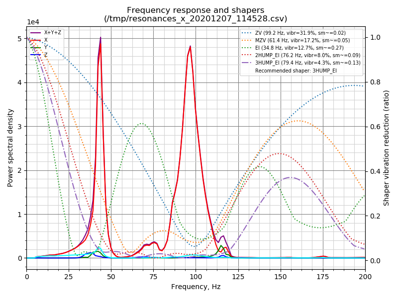
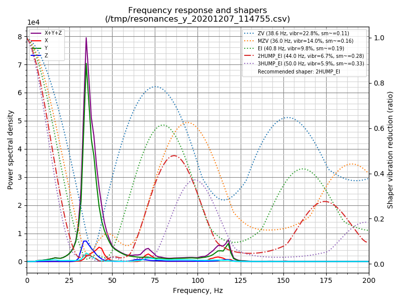
 aschor
on 7 Dec 2020
aschor
on 7 Dec 2020
@dmbutyugin I have a question regarding the damping_ratio config parameters: https://www.klipper3d.org/Config_Reference.html#input_shaper
There seems to be a general lack of clarity as to how to use it.
In the Resonance Compensation document it mentions we probably shouldn't change the damping ratio unless we can measure vibrations accuratele, but in the docs for actually measuring the vibrations, it doesn't say how we are supposed to determine what a good damping ratio would be?
Then reading in the issues, there is one where a good value was found to be 0.04 for one use case, but not much else.
Basically I'm looking for clarity, so we can update the docs by either not recommending changing it, or by specifying what it represents and how to tune it.
grigi
on 7 Dec 2020
Hi @aschor, thanks for giving it a try.
Hi @dmbutyugin just switched to this branch to do my shaper calibration. I setup in my config max_accel=7000 and max_accel_to_decel=7000. is this "normal" that when I run SHAPER_CALIBRATE, I see "max_accel_to_decel: 9000" scrolling, and indeed when isueing a "set_velocity_limit" command, it is set to 9000. If I set it back to 7000, run shaper_calibrate ........ then again my max_accel_to_decel has changed to 9000 ?
It is "normal". Kevin considers accel_to_decel parameter an internal implementation detail. And in principle, the user can request higher accel_to_decel than in the config. So Klipper reports this value as-is, as the test requested. You don't need to worry about that at all.
Also, when I tried to graph the data :
```
~/klipper/scripts/graph_accelerometer.py /tmp/resonances_x_*.csv -o ~/tmp/resonances_x.png
...
ValueError: could not convert string to float: freq
graph_accelerometer.py script only accepts the raw accelerometer data (resonances_*.csv files contain processed data). You should use calibrate_shaper.py in this case. Since this question seems to reappear, I'll make a change in the script to give a more meaningful error report. And you can generate the raw data with TEST_RESONANCES ... OUTPUT=raw_data.
Recv: // Recommended shaper_type_y = 2hump_ei, shaper_freq_y = 37.5 Hzafter update :
Fitted shaper 'zv' frequency = 99.2 Hz (vibrations = 31.9%, smoothing ~= 0.022)
Fitted shaper 'mzv' frequency = 61.4 Hz (vibrations = 17.2%, smoothing ~= 0.054)
Fitted shaper 'ei' frequency = 34.8 Hz (vibrations = 12.7%, smoothing ~= 0.266)
Fitted shaper '2hump_ei' frequency = 76.2 Hz (vibrations = 8.0%, smoothing ~= 0.093)
Fitted shaper '3hump_ei' frequency = 79.4 Hz (vibrations = 4.3%, smoothing ~= 0.130)
Recommended shaper is 3hump_ei @ 79.4 Hz

pi@octopiklipper:~ $ python ~/klipper/scripts/calibrate_shaper.py /tmp/resonances_y_20201207_114755.csv -o tmp/resonance
s_y.png
Fitted shaper 'zv' frequency = 38.6 Hz (vibrations = 22.8%, smoothing ~= 0.107)
Fitted shaper 'mzv' frequency = 36.0 Hz (vibrations = 14.0%, smoothing ~= 0.157)
Fitted shaper 'ei' frequency = 40.8 Hz (vibrations = 9.8%, smoothing ~= 0.194)
Fitted shaper '2hump_ei' frequency = 44.0 Hz (vibrations = 6.7%, smoothing ~= 0.279)
Fitted shaper '3hump_ei' frequency = 50.0 Hz (vibrations = 5.9%, smoothing ~= 0.328)
Recommended shaper is 2hump_ei @ 44.0 Hz
I'm not sure about the value 'before', but the currently suggested shapers and parameters do make a lot of sense for your printer (given the charts, at least). You can give them a try and see how they perform.
dmbutyugin
on 7 Dec 2020
@grigi
@dmbutyugin I have a question regarding the
damping_ratioconfig parameters: https://www.klipper3d.org/Config_Reference.html#input_shaper
There seems to be a general lack of clarity as to how to use it.In the Resonance Compensation document it mentions we probably shouldn't change the damping ratio unless we can measure vibrations accuratele, but in the docs for actually measuring the vibrations, it doesn't say how we are supposed to determine what a good damping ratio would be?
Then reading in the issues, there is one where a good value was found to be 0.04 for one use case, but not much else.
Basically I'm looking for clarity, so we can update the docs by either not recommending changing it, or by specifying what it represents and how to tune it.
Well, as the docs suggest,
... If the damping ratio of the printer is known for each axis, the shaper can be configured more precisely and it will then reduce the resonances in a bit wider range of frequencies. However, the damping ratio is usually unknown and is hard to estimate without a special equipment, so Klipper uses 0.1 value by default, which is a good all-round value. The frequency ranges in the table cover a number of different possible damping ratios around that value (approx. from 0.05 to 0.2).
So, unless you know how to do it, please leave damping ratio parameters at their default values (and maybe I should update the doc to make it more explicit). If you do want to know, there are, theoretically, some methods, for example "3 dB method", which allows to estimate Q-factor using the data already available from the accelerometers, and then get damping_ratio = 1 / (2 * Q). However, I am not even sure how accurate this method would be for 3D printers. There are probably other approaches out there that can work.
dmbutyugin
on 7 Dec 2020
I think that many 3D printer frames are not well maintained, so their damping ratios probably float with the mood of the day. Trying to fine-tune that in would be quite time consuming.
I think the advise of tightening up the frame is probably better than fine-tuning the damping_ratio.
grigi
on 7 Dec 2020
Indeed, the default damping_ratio of 0.1 works very well for a wide range of _actual_ damping ratio values. There is actually quite little to gain from fine-tuning it.
dmbutyugin
on 7 Dec 2020
Hi, small update on my side. I did try those input shaper parameters (max_smoothing 0.16, trying to have same amount of smoothing in X and Y not sure if that makes sense) :
X : #Fitted shaper '3hump_ei' frequency = 76.2 Hz (vibrations = 4.2%, smoothing ~= 0.141)
Y : #Fitted shaper '3hump_ei' frequency = 71.6 Hz (vibrations = 8.7%, smoothing ~= 0.160)
and the results are quite good, I can't see a difference in acceleration from 1500 to 7000.
BUT. I had great hopes to get rid of my vertical banding issues (on PETG and ABS, quite not visible on PLA), and I havent it seems. So MAYBE it is belt ringing, cause it _seems to have a 2mm spacing (even if on the X it follows the slope for some ringings).
@dmbutyugin : is there a way to use the accelerometer, and capture + graph data while moving the head in a say 10cm square ? to CONFIRM that there is a frequency generated while moving, that is not there while shaper_calibrate'ing ? (induced by trynamic, induced by belts, oscilating bed or whatever).
PETG @ 80mm/s, 0.28 layer height :
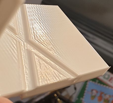
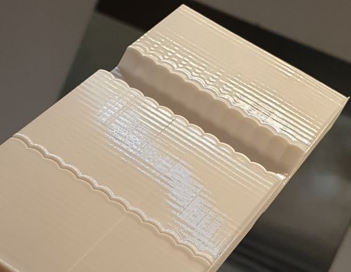
by the way, this is the tuning gap along the X axis (so Y oscilations) :
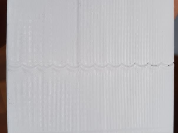
(yes, I lost steps in the way, I'm investigating it)
aschor
on 8 Dec 2020
Those consistently repeatings lines look very much like belt ringing. If they are the same pitch as your belts (e.g. 2mm for GT2), then I'd say your belts are possibly too tight?
grigi
on 8 Dec 2020
Those consistently repeatings lines look very much like belt ringing. If they are the same pitch as your belts (e.g. 2mm for GT2), then I'd say your belts are possibly too tight?
thanks (I already tried before to loose them, to no avail. I think that if I rule resonance out, then maybe the belt and pulleys profiles don't match. But I already changed belt and pulley ... next time I think it's time to order them all from E3D and see if that solves my issue)
aschor
on 8 Dec 2020
I have really cheap stuff on my printer, and I don't have that issue. I would look at the motion system first.
The ripples look too even to be anything other than the motion system.
Some suggestions:
- Check to see that the idlers are not on a bent rod.
- Ensure that the pulleys are centered on the stepper motors correctly.
- Ensure that the belt, pulleys and idlers are straight. if they are misaligned (for example by bad design on my Anet A8's bed where the motor mount is not lined up correctly) you will get similar issues as the belt repeatedly catches on the lip of the pulley.
- The tension in the belts need to sound like a bass guitar. It's better to have them slightly too tight than too loose.
grigi
on 8 Dec 2020
@aschor
I did try those input shaper parameters (max_smoothing 0.16, trying to have same amount of smoothing in X and Y not sure if that makes sense) :
Looking at your previous charts, it actually doesn't make sense: your Y axis seems to be heavier, and the lowest resonance frequency is lower. So you may need to allow higher smoothing for it. Maybe you should set less aggressive max_smoothing limit, like 0.25 or 0.2.
X : #Fitted shaper '3hump_ei' frequency = 76.2 Hz (vibrations = 4.2%, smoothing ~= 0.141)
Y : #Fitted shaper '3hump_ei' frequency = 71.6 Hz (vibrations = 8.7%, smoothing ~= 0.160)and the results are quite good, I can't see a difference in acceleration from 1500 to 7000.
BUT. I had great hopes to get rid of my vertical banding issues (on PETG and ABS, quite not visible on PLA), and I havent it seems. So MAYBE it is belt ringing, cause it _seems to have a 2mm spacing (even if on the X it follows the slope for some ringings).
This is not ringing pretty much 100%. The lines marked with red are ringing:
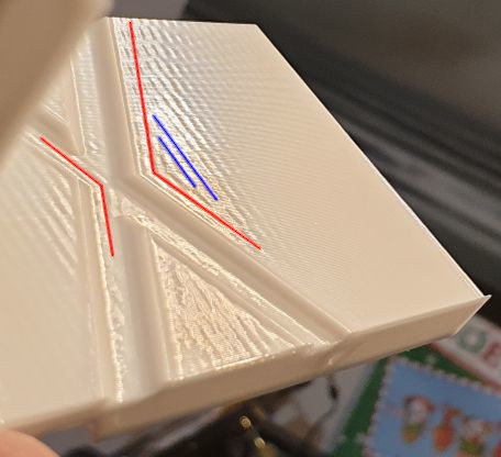
but the ones marked with blue are not (they don't follow the shape of the edges of the model).
@dmbutyugin : is there a way to use the accelerometer, and capture + graph data while moving the head in a say 10cm square ? to CONFIRM that there is a frequency generated while moving, that is not there while shaper_calibrate'ing ? (induced by trynamic, induced by belts, oscilating bed or whatever).
You can use ACCELEROMETER_MEASURE command, and then graph_accelerometer.py script with -s parameter.
Just a note on
- The tension in the belts need to sound like a bass guitar. It's better to have them slightly too tight than too loose.
I don't fully agree here, too tight belts can produce similarly looking defects. BTW, some time ago I came across this guide that have some suggestions on how much to tighten the belts. I think the suggested values are a bit too aggressive, but they can be used as some baseline.
thanks (I already tried before to loose them, to no avail. I think that if I rule resonance out, then maybe the belt and pulleys profiles don't match. But I already changed belt and pulley ... next time I think it's time to order them all from E3D and see if that solves my issue)
In principle, these could also be bearings or wheels / rails (depending on what you have on your printer).
dmbutyugin
on 8 Dec 2020
@1N4148 BTW, you have fairly large resonance frequency on Y axis on Ender 3. Did you make some upgrades to stiffen the frame of the printer or the bed?
dmbutyugin
on 8 Dec 2020
@dmbutyugin You mean the peak of 3.5 on Y? The base frame is mounted on a concrete tile. And there are metal corner brackets for each axis. Printbed is a FR4 sheet attached with a magnetic foil. It's a bed slinger so there's not much room for improvement. But the sensor position wasn't optimal, it was clamped on the front left edge as you can see in the Z-axis resonance.
BTW: How can we use the measurement data to quickly adjust belt tension? Rapidly moving some way and suddenly stop to get a step response? This should lead to an oscillation on start or stop which has a spectrum. So it should be possible to optimize step response like tuning the capacitor on an oscilloscope's probe? Doing some shaking, getting a total value, tightening or loosening belt, shake again, ...
As an intermediate step before tuning shapers with final resonance profile.
BTW²: If there would be a way to merge scurve-shaping & axdl345 branches I could test more often without having to switch ;)
1N4148
on 8 Dec 2020
@1N4148
@dmbutyugin You mean the peak of 3.5 on Y?
The one slightly below 50 Hz. So, yes.
And there are metal corner brackets for each axis.
Like, 2020 corner brackets?
It's a bed slinger so there's not much room foor improvement.
But the sensor position wasn't optimal, it was clamped on the front left edge as you can see in the Z-axis resonance.
That's actually expected: the bed also has that resonance, when its front and back swing vertically in the opposite direction. So it's good that you catch that resonance too.
BTW: How can we use the measurement data to quickly adjust belt tension?
I don't think that's the right way to adjust the tension. I posted the link to the guide in the previous post, I think that's more 'right' way to do it. Besides, I found that the belt tension has relatively small impact on the resonances (as long as the belt is not loose). I was getting the lowest resonance at 31 or 35 Hz (with a glass bed and a steel magnetic surface respectively), and I found that belt tension and springs have no impact on that resonance. I suspect its an eigenfrequency of the frame itself; it could be possible to stiffen it though, and it seems that you have it in a really good state in the end.
BTW²: If there would be a way to merge scurve-shaping & axdl345 branches I could test more often without having to switch ;)
If the further feedback is positive about the updated shaper tuning algorithm and smoothing limiting then I hope to push it to the mainline Klipper in the near future. And I regularly sync scurve-shaping to the mainline, so it already has the base accelerometer support, and it will then get the updated algorithm as well. I don't think I'll be creating a temporary branch with a combination of scurve and my adxl345 branch to avoid confusion (and to have less work on my side).
dmbutyugin
on 8 Dec 2020
@dmbutyugin You mean the peak of 3.5 on Y?
The one slightly below 50 Hz. So, yes.
Maybe I'm tightening the bed screws a bit more. Already replaced the springs against silicone bumpers. When crossing the first resonance there's a sound like a starting turbo prop.
And there are metal corner brackets for each axis.
Like, 2020 corner brackets?
I've installed 40x40x40 on front of the Z-Base, 30x40x40 below the Y-Axis and some 40x40x20 in the top corners of the Z-strut.
BTW: Did I miss something as I had to capture raw data, process it in the shell and move the images to the webserver's base directory to view the resulting graphs as there is no local screen on the Pi. Is there a quicker way? I'm finally switched from OctoPrint to Fluidd.
1N4148
on 8 Dec 2020
Maybe I'm tightening the bed screws a bit more. Already replaced the springs against silicone bumpers.
Well, installing more stiff springs or tightening the belt didn't seem to affect the first resonance in my case. I have a strong reason to believe that this are the vibrations of the Π part of the frame over which X axis moves in Z direction. I'm planning to test some upgrades and see if they help. But those brackets on your printer may indeed have contributed to this the most.
When crossing the first resonance there's a sound like a starting turbo prop.
That's normal, depending on the amplitude of the resonances.
BTW: Did I miss something as I had to capture raw data, process it in the shell and move the images to the webserver's base directory to view the resulting graphs as there is no local screen on the Pi. Is there a quicker way? I'm finally switched from OctoPrint to Fluidd.
I don't know, I usually just copy the CSVs with the raw data to the laptop and run the scripts there - this way, its faster for me to iterate.
dmbutyugin
on 10 Dec 2020
As my printer's base frame is screwed to a concrete tile I cannot see how resonances of the top strut profile would transfer to the bed. If I "ping" the bed with my finger, I'm getting those vibrations on the bed not on the frame. And from the measurements on the bed, there were not much resonances in x-direction (on the measurements for the x-axis the sensor was tilted 90° so x & y must be swapped). So the resonance is only in the direction of normal movement.
Is there a way to make vibrations of a specific frequency so we could check what measures are efficient at this frequency? How do you calculate the moves for a specific frequency?
1N4148
on 10 Dec 2020
As my printer's base frame is screwed to a concrete tile I cannot see how resonances of the top strut profile would transfer to the bed.
That might also be a large contributing factor to the absence of vibrations at low frequencies.
Is there a way to make vibrations of a specific frequency so we could check what measures are efficient at this frequency? How do you calculate the moves for a specific frequency?
I was just running the full tuning process (it is relatively fast) and generate the raw accelerometer output. Then two outputs can be compared, e.g. with
$ graph_accelerometer.py -c raw_data_y_1.csv raw_data_y_2.csv
In principle, one can also run something like
TEST_RESONANCES AXIS=Y FREQ_START=34 FREQ_END=36 HZ_PER_SEC=0.05
But I would rather run the full test since some changes may affect other resonances as well.
dmbutyugin
on 10 Dec 2020
Stiffening was the first thing I did with my Ender 5 before it printed for the first time. One thing I want to try in the future are diagonal or curved metal stiffeners from the top strut to the base.
It's quite difficult to find further optimization potential and to compare the absolut resonance level with other printers of the same type. Too few results to compare. Cannot say how much my remaining resonances are still influencing the prints. For now I've set my limit to 2000mm²/s as it's imho a good compromise between overall speed and quality.
1N4148
on 11 Dec 2020
@1N4148
My results above are from an Ender 5 (https://github.com/KevinOConnor/klipper/issues/3027#issuecomment-710894913) as well. Currently working again on the bed and electronics, so I cannot test. Hopefully during upcoming weekend.
@dmbutyugin
Are the power spectral density values comparable between the design iterations of the script?
2020/08/30 Only minor frame stiffening
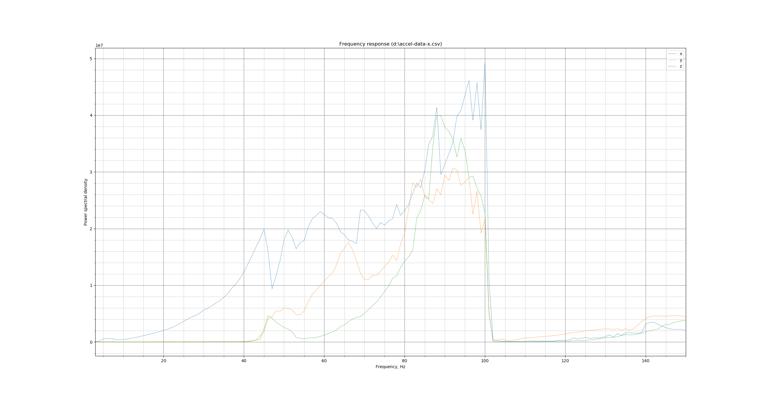
2020/10/06 reworked frame and damping feet
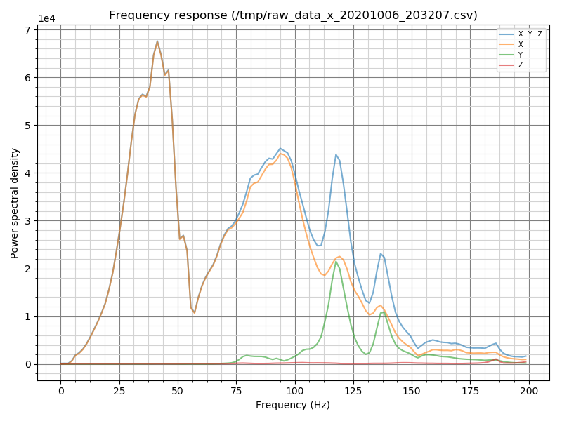
2020/10/17 Linear rails added for x and y
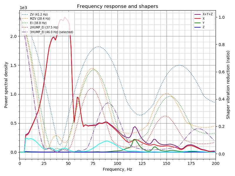
The power spectral density went down from 1e7 to 1e3, which would mean (if comparable) the improvements brought down the value by a factor of ~1000
Sineos
on 11 Dec 2020
@dmbutyugin - looks interesting! Unfortunately, I haven't gotten a chance to look at this first hand in the last few weeks. I've completed the toolhead upgrade to my "makergear m2" printer (new hotend, new stepper drivers, now 24V). So, I'd like to redo the acceleration tests from scratch (both the test prints and accelerometer tests). Alas, I fear I'm probably a couple weeks out from completing that.
FWIW, I have seen reports that the current "shaper recommendations" seem to lean towards "heavier smoothing". That is, in various reports I've seen, the recommendation almost always is 3hump_ei or 2hump_ei. Your new code with limits on smoothing sounds interesting.
Cheers,
-Kevin
KevinOConnor
on 11 Dec 2020
@Sineos
Sometimes, the charts are compatible between the versions of the scripts. Unfortunately, not in that case between 1 and 2 for sure, and actually likely between 2 and 3. Between 1 and 2 the algorithm to process the accelerometer data was changed (using Welch's algorithm), which introduced averaging and so the magnitude of the values changed a lot, and between 2 and 3 I think I introduced additional normalization by frequency magnitude (it looks that way at least) which also changed the amplitude of vibrations, especially for high-frequency vibrations. You can still see resonances as peaks on all charts, but their magnitude is likely not possible to compare directly. Anyways, i think the most important part is the frequency of resonances.
dmbutyugin
on 11 Dec 2020
@KevinOConnor OK, anyway I'll prepare some documentation for this feature and integrate it properly not just into the script, but also to the Klipper auto-tuning, and will make a PR. It will take a bit of time, and then hopefully more people would give it a try.
FWIW, I have seen reports that the current "shaper recommendations" seem to lean towards "heavier smoothing". That is, in various reports I've seen, the recommendation almost always is 3hump_ei or 2hump_ei. Your new code with limits on smoothing sounds interesting.
The choice of 3hump_ei or 2hump_ei is, in general, not very surprising: the accelerometer can detect multiple resonances, and it is typically not sufficient to apply MZV or EI shaper to suppress them all. So the choice of 2hump_ei or 3hump_ei is usually more natural. And the algorithm chooses the 'next' shaper only if it gives a significant improvement over all 'previous' shapers.
The real 'problem' with the current algorithm is that for each input shaper it finds the perfect parameter that gives the minimal vibrations. However, sometimes this leads to too low shaper frequency for little extra benefit. The new algorithm tries to mitigate that by trying to find the 'good enough' shaper frequency: the one that's maybe just marginally worse that the best frequency in terms of remaining vibrations, but that provides less smoothing. And then one can additionally restrict the projected smoothing to potentially trade some extra vibrations for less smoothing.
dmbutyugin
on 11 Dec 2020
I've put together a PR #3658 with the improved shaper auto-tuning algorithm and wrote some documentation for it. The algorithm is the same as what was tested in adxl345-spi branch, but give docs a try and let me know what you think. And try the new algorithm if you haven't tried it already.
dmbutyugin
on 19 Dec 2020
Related issues
 jannoke
·
3Comments
jannoke
·
3Comments
 krpepe
·
5Comments
krpepe
·
5Comments
 speendo
·
3Comments
speendo
·
3Comments
 LazaroFilm
·
6Comments
LazaroFilm
·
6Comments
 smokez89
·
4Comments
smokez89
·
4Comments