I am about to install these with the one wire off MS3 tomorrow when my new board comes Like Kevin did. I can't seem to find anything definitive with these BigTreeTech TMC2208 V2.0 drivers and pad jumping for UART. Best I can tell it is the space between the pad and the solder joint beside of it but I could be wrong. Can anyone look at the picture and confirm this is what I need before I solder it and hook it up to the board and klipper? I know this isn't an exact klipper issue but I would appreciate any help given. Thank you in advance

 Maximuscr31
All 24 comments
Hi Maximuscr31, I don't have the exact same TMC2208 as yours but the same situation(no docs on what to bridge). I used an OHM meter to confirm that one of the two pads was indeed connected to the PDN pin(in my case). I then 'assumed' that the other side of the two pads was for bridging the UART(since all other guides worked this way). Tested it on one and all was good. Currently have one wire working with Marlin 1.1.9/MKS Gen L and looking at trying Klipper out very soon.
 Gomer05
on 2 Oct 2018
Gomer05
on 2 Oct 2018
So I bridged the solder pads and tested with a meter for continuity and got it on the pdn pin and the solder blob so apparently I chose correctly I think. I also tested from the solder to a cable attached to ms3 on the pdn side. It had continuity. Problem is the height of a dupont connector. Before I solder the wire to ms3 anyone have bright ideas for connecting it a little less permanently that will fit under the driver?
Maximuscr31
on 2 Oct 2018
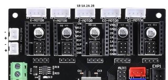
On my Gen-L board, I found that the MS3 pin on the driver is routed to a jumper pin underneath the stepper driver. I removed the jumper from the jumper pin and used a jumper wire to route that pin on the board to another pin on the board that is connect to the micro-controller. The jumper pin under the driver was pointing up, but I just pushed the pin diagonally so that the jumper cable fits and does not touch the stepper driver.
-Kevin
 KevinOConnor
on 2 Oct 2018
KevinOConnor
on 2 Oct 2018
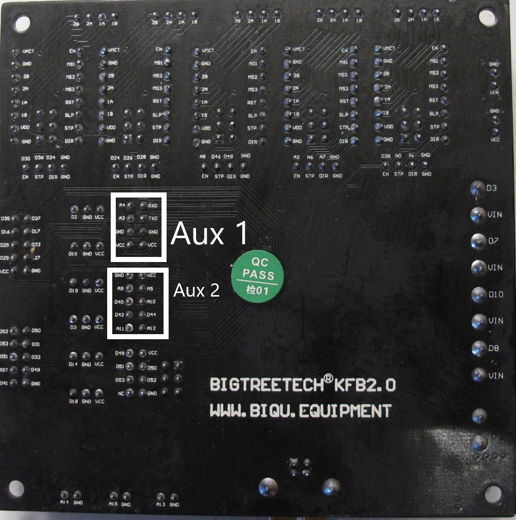
I cringed at bending the pins but did it that way. I also got most of the config done but I am lost on the pins. I was planning on using D44, D42, D40 from Aux 2. Can I use A labeled pins from Aux 2 as well? I really have no never messed with something that was plugin on arduino and had to set custom pins. So please explain it to me like a complete idiot because I am. I have been reading for 6 hours on pin assignment. At this point it is either overload or I am over complicating something simple. I looked at this link https://github.com/MarlinFirmware/Marlin/blob/1.1.9/Marlin/fastio_1280.h . That didn't list D44 or D42 or D40. I will upload pictures of the board with front and back pins. I have nothing custom on my board other than the #"RepRapDiscount 128x64 Full Graphic Smart Controller" on exp1 and exp2.
I am hoping this will end up being a great tutorial/instructional for installing these with klipper on a budget who are not formally trained in electronics.

Maximuscr31
on 3 Oct 2018
Can I use A labeled pins from Aux 2 as well?
Yes. If you're using "pin_map: arduino" then "a5" would be "analog5" in the klipper config.
That didn't list D44 or D42 or D40
If you're using "pin_map: arduino" then just use "ar44", "ar42", and "ar40". The pins are there though - look for DIO40_PIN which would be "PG1" in Klipper - see: https://github.com/MarlinFirmware/Marlin/blob/1.1.9/Marlin/fastio_1280.h#L312
-Kevin
KevinOConnor
on 3 Oct 2018
I think I got it working. I have just done the X axis. I homed and it moved correctly. I assume that all is well? Any tests I can do to make sure? It is dead silent. I have never heard my printer so quite. Here is my klippy log just to look over.
klippy.log
Maximuscr31
on 3 Oct 2018
Looks like it is not working but in legacy despite hooking it up right.
Starting heater checks for extruder
Config error
Traceback (most recent call last):
File "/home/pi/klipper/klippy/klippy.py", line 144, in _connect
cb('ready')
File "/home/pi/klipper/klippy/extras/tmc2208.py", line 197, in printer_state
self.set_register(reg_name, val)
File "/home/pi/klipper/klippy/extras/tmc2208.py", line 214, in set_register
self.ifcnt = ifcnt = self.get_register("IFCNT")
File "/home/pi/klipper/klippy/extras/tmc2208.py", line 208, in get_register
"Unable to read tmc2208 '%s' register %s" % (self.name, reg_name))
Error: Unable to read tmc2208 'stepper_x' register IFCNT
Found this by ghost.
https://github.com/KevinOConnor/klipper/issues/542#issuecomment-414609129
Looks like he was unable to get them working. I might have to send them back and try a different brand.
Maximuscr31
on 3 Oct 2018
It's rather interesting that these BitTreeTech TMC2208 drivers place the chip (and other components) on the top of the board.
Most Trinamic driver modules place it underneath, with the heatsink directly on the board over the thermal vias under the chip:
http://learn.watterott.com/silentstepstick/faq/#why-is-the-trinamic-driver-chip-on-the-bottom-pcb-side
https://www.watterott.com/media/images/popup/20170003_2.jpg
Do you have an impression how well the cooling works with the heat sink stuck to the chip?
 ruevs
on 3 Oct 2018
ruevs
on 3 Oct 2018
I do not. I have repackaged the one I tried and sending it back to Amazon today.
Maximuscr31
on 3 Oct 2018
I ordered the fysetc tmc2208 drivers from Amazon today. They should be here Monday for those wondering. I will update with results once they are here and installed.
3D Printer Stepper Motor Driver, FYSETC TMC2208 V1.2 Stepstick Stepper Motor Driver Module Carrier with Heat Sink Screwdriver for 3D Printer Controller Boards Ramps1.4 MKS Gen, Red 5 Pcs https://www.amazon.com/dp/B07DXM6Z92/ref=cm_sw_r_cp_apa_yqUTBb8SYB52K
Maximuscr31
on 5 Oct 2018
The new drivers are in but I am having a new issue. Closing this and Opening a new ticket.
Maximuscr31
on 9 Oct 2018
@Maximuscr31
did you find out which one to bridge on begtreetech tmc 2208?
 ghost
on 10 Jan 2019
ghost
on 10 Jan 2019
@Maximuscr31
did you find out which one to bridge on begtreetech tmc 2208?
 Alexdad76
on 15 Jan 2019
Alexdad76
on 15 Jan 2019
@Alexdad76 i did meanwhile. I messured by hand the spot and its that one which is showen here in the picture of post 1 here. Uart works great but steppers are worser than watterotts or fysetec. on my corexy it has not enough power in stealthchop. On Watterotts i travel 300 in steltchop with vref .6 or .8. On bigtreetech i need at least 1.1. Then they fail due to overheat. Really cool product .....
ghost
on 15 Jan 2019
@derdigge I have a fysetec in UART, but the steltchop mode is terrible, I turned it off.
Alexdad76
on 15 Jan 2019
@Alexdad76 and @derdigge can you please tell what tension do you use for you steppers? (12v, 24v, etc)
 danielfmo
on 22 Jan 2019
danielfmo
on 22 Jan 2019
@Alexdad76 i disagree. My printer is doing easily 120mm/s printing and 300mm/s travel with stealthchop delivering awsome prints. It is depending on so many factors. The video is 120infillprint with 3500 acceleration and travel is 250 to give you an ide what can be done. https://www.youtube.com/watch?v=x48u0KkOHJw
@danielfmo I am on 24v system. I would highly recommend this if you are going to use stealthchop2. I had awful results on another printer with stealthchop2 and 12v.
But the bigtreetech drivers were really really bad compared to Watterott and Fysetec.
ghost
on 22 Jan 2019
@Alexdad76 and @derdigge can you please tell what tension do you use for you steppers? (12v, 24v, etc)
12 v.
Alexdad76
on 24 Jan 2019
The bigtreetech drivers never did work in uart for me or another tester. I soldered the pads in video but it never enabled uart. I got the fystec and did the same and it immediately worked. I also would recommend going to 24v as well.
Maximuscr31
on 1 Feb 2019
@Maximuscr31 mine do work very well. I have four of them on a BigTreeTech SKR v1.1 at 24v and UART. Have even one on the extruder and so far so good (~2 weeks)
danielfmo
on 1 Feb 2019
@Maximuscr31 mine do work very well. I have four of them on a BigTreeTech SKR v1.1 at 24v and UART. Have even one on the extruder and so far so good (~2 weeks)
@danielfmo did you solder as described above and use the PDN pin for connection?
 totalitarian
on 23 Apr 2019
totalitarian
on 23 Apr 2019
Do NOT buy TMC2208 drivers with the main chip on top! They do not support UART mode by design. BIGTREETECH V2.0 is just one of them! Soldering the jumper pads does nothing. They can only be used as standalone mode. Do NOT buy if you intend of use UART.
 bobhuang1
on 25 Jun 2019
bobhuang1
on 25 Jun 2019
Is that true? I soldered the bridge, I get electrical connectivity to the pins on the central chip, but in my SKR Pro 1.1 board, I'm not getting any UART connection to the TMC2208 V2.0 step stick I have.
I'd purchased 4 TMC 2209's for the motors, but wanted to use some 2208's for the extruders. Now I'm blowing even more money on more TMC2209's :(
== John ==
 jgwinner
on 16 Dec 2019
jgwinner
on 16 Dec 2019
I do not have first hand knowledge, but I have seen reports that some "tmc2208 v2.0" stepsticks have PDN-UART connected to a different pin than the controller board is expecting. Some users have reported success by soldering two pins together - see: https://github.com/KevinOConnor/klipper/issues/542#issuecomment-560748931
-Kevin
KevinOConnor
on 17 Dec 2019
Related issues
 amaximchuk
·
6Comments
amaximchuk
·
6Comments
 talfari
·
5Comments
talfari
·
5Comments
 speendo
·
3Comments
speendo
·
3Comments
 jannoke
·
3Comments
jannoke
·
3Comments
 BlackStump
·
3Comments
BlackStump
·
3Comments
Most helpful comment
@Maximuscr31 mine do work very well. I have four of them on a BigTreeTech SKR v1.1 at 24v and UART. Have even one on the extruder and so far so good (~2 weeks)