Circuitverse: ASCII capable display
I am submitting a -
Feature Request
Describe your feature -
Currently, we have an ASCII TTY display, and we are able to make displays using LEDs. This is all great, but at the moment there isn't much of a way to display ASCII on top of a pixel display, and displaying ASCII characters on a display is a bit impractical. So, why don't we make a component able to display both ASCII characters, as well as with a color background, similar to how many early terminal computers used.
ASCII Capable Display
The display should have an X coordinate and Y coordinate (with customization bitwidth, up to 8 bit), a background RGB input, foreground (ASCII) RGB input, ASCII character input, write input, clear, and 4 "shift" inputs which will shift the whole image in one of 4 directions (up, down, left, right). There should also be a DMA pin (if/when they are added) to be able to asynchronously fill the display.
Image

Are you working on this issue? (Yes/No)
No.
 blane1257
All 11 comments
@blane1257 @satu0king
I would like to be assigned this issue.
 abdullah-mohamed
on 5 Mar 2019
abdullah-mohamed
on 5 Mar 2019
that was an accident
blane1257
on 5 Mar 2019
@satu0king _help needed_
I am a bit confused because I am new to open source contribution.
I have cloned the whole project to my local host, but I can't find my way through it.
As I am looking forward for project 1 application, I have already read subCircuit.js as it was referenced in the project.
I also skimmed through public/js files, I have seen circuitElement constructor function in many files and I thought I can start working from there as I will be making a new element but I have been looking for the file that contains this constructor function but I couldn't find it at all.
abdullah-mohamed
on 5 Mar 2019
@abdullah-mohamed is a js Class in js/logix.js file
 SubhajitCode
on 5 Mar 2019
SubhajitCode
on 5 Mar 2019
This would be an awesome component to have. :-)
@abdullah-mohamed , if you want to tackle this you might want to start by taking a look at a couple of other PRs where I added some new components, for example: #172, #113
We also need to decide on the addressing and color formats for this. For example, is it a full RGB (24bits/char) or less? And does each char has a foreground+background color or not?
 fpintos
on 5 Mar 2019
fpintos
on 5 Mar 2019
I think each character/x,y pos should definitely have both background and foreground color, and 8 bits per color (24 bits) is ideal, but it might be excessive. I do think 4 bits per color (12 bits total) is the minimum, though. And just to be clear, I think it will be most aesthetically pleasing if there are no borders between the pixels/characters, similar to what is shown in the original image. I also think that, if it adds too much complexity, we could forego the 4 way shift inputs, instead just leaving a single shift which shifts the image up (sort of like a "Ln")
This type of display makes me really excited, as right now we could have an entirely text based ASCII console, and an LED display, but neither have felt quite complete. You could have a simple text based operating system, and you could display an image, but it hasn't really felt like a graphical interface. But with a display like this, now you can combine the ASCII display in with the LED display, not necessarily in such a way to make images, but rather to make an intuitive and pleasing interface, as we can now create something reminiscent of MS-DOS.

On the topic of MS-DOS, now that I look at that image, many of the structures that would be useful in a similar context (like backgrounds, windows, buttons) would be significantly easier and faster to draw if you could fill a rectangle between two coordinates, but I'm not sure how to go about that.. A basic display+GPU I made a while back had a similar feature of filling rectangles, but this was accomplished by having two separate coordinate inputs, but I don't think that's the best way to go with this component...
blane1257
on 5 Mar 2019
@blane1257 _thanks for the details_
This is my visualization of the tool, Correct me if there is something wrong.
The user will choose the element from the sequential elements dropdown.
By default it will have some height and width, which the user can change by entering custom values
in the sidebar, now the number of characters will be height * width.
But
If I get this right, this will be an element -similar to the lcd element.
It will be receiving a stream of pins as follow
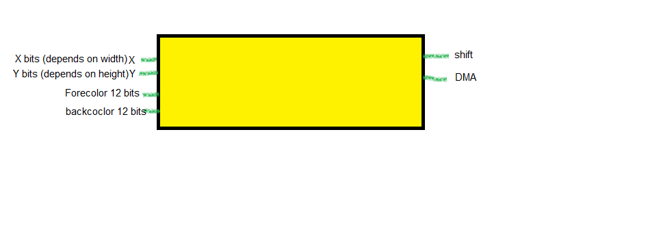
also can you provide some use cases for shift pin(s)? why do we actually need them/it ?
abdullah-mohamed
on 6 Mar 2019
Instead of a height and width variable, I think there should just be independent X and Y bitwidths, as this makes things a bit simpler. There should also be a clear button. The shift pin(s) would be used to shift the entire image up, down, left, or right. Originally I had the idea of this as a shift "up" sort of like a "Ln" or new line, useful in the case of a console or terminal, instead of redrawing the entire image just to shift it up. I later realized it may be useful to move the image in other directions as well.
blane1257
on 6 Mar 2019
@blane1257
ok, I will assign it 6bits each allowing for 64*64 cells and will try to make things as abstract as possible in order to modify it in the future.
for the shift pins, I quite get it. I will start by 1 shift and will extend into 4 in the future.
for the clear button, I think this will be easy as its function will be to clear the whole screen.
another question, Will this element be updated each clock pulse ?
For each pulse, We will get:
1 - X input
2- Y input
3- fore color
4- background color
5- write input/enable pin. (must be 1 to allow changes to take place)
6 - of course a 7bit data pin
Is there anything missing ?
For now, These pins will provide o/p to the user and will upgrade to add more pins to accept I/p from the user.
abdullah-mohamed
on 6 Mar 2019
There also needs to be an ASCII character input, other than that is seems fine! And yes, every clock pulse should be fine.
blane1257
on 6 Mar 2019
No activity on this issue for a prolonged duration, will be closed if no further activities in next 7 days
![github-actions[bot] picture](https://avatars.githubusercontent.com/in/15368?v=4&s=40) github-actions[bot]
on 7 Mar 2020
github-actions[bot]
on 7 Mar 2020
Related issues
 ryuk156
·
9Comments
ryuk156
·
9Comments
 1337w0rm
·
3Comments
1337w0rm
·
3Comments
 satu0king
·
9Comments
satu0king
·
5Comments
ryuk156
·
4Comments
satu0king
·
9Comments
satu0king
·
5Comments
ryuk156
·
4Comments