Circuitverse: Subcircuit Layout upgrade
Referencing #36.
Until recently subcircuits had very strict dimensions and positions and little could be done to move the node positions. As of now, subcircuits have flexible dimensions and node positions can be changed.
Moving forward, the design pattern has to be considered to ensure extensibility and ease for both development and the users.
Some of the features are to be considered to be implemented on the subcircuit layout.
- [ ] Output elements like LEDs (Digital+analog+RGB)
- [ ] Output elements like seven segment display, display matrix
- [ ] Input elements like button
- [ ] Input elements like clock, stepper
- [ ] Custom text elements in between
This would open a whole range of exciting possibilities. If the initial design is good, implementing these features will be easy. However, it is tricky as all LEDs and other output elements need not be part of the subcircuit. Providing a feature for the user to easily pick and chose his features will be difficult. Storing and manipulating the data from the development point of view is tricky too.
@blane1257 @HypheX and thoughts? comments?
 satu0king
All 19 comments
This all sounds pretty great. Also, I love the text idea! perhaps it could have a few options for color, font, and size, too.
 blane1257
on 9 Nov 2018
blane1257
on 9 Nov 2018
This all sounds pretty great. Also, I love the text idea! perhaps it could have a few options for color, font, and size, too.
Yes this can be done too
satu0king
on 9 Nov 2018
I agree with blane, it sounds great! Can't wait for these features, I am "hyped".
 HypheX
on 9 Nov 2018
HypheX
on 9 Nov 2018
I'll look into making some assets
Can I be marked as an "asignee"?
 jbox144
on 3 Dec 2018
jbox144
on 3 Dec 2018
surface elements such as buttons and LEDs should be individually togglable if possible
blane1257
on 10 Jan 2019
Could the input/output elements just have an extra property that tells if they show up in the layout or not?
We also need to consider if their labels show up or not; I can think of cases where we would want to and in cases where we would not want to.
The size of the leds might also be important; in a project like this https://circuitverse.org/users/1935/projects/5010, I would love to have the LEDs in the "4-pixel cell" circuit, but they would need to be big enough to fill the layout, since the number of inputs dictates the size of the layout.
 fpintos
on 17 Jan 2019
fpintos
on 17 Jan 2019
@fpintos These are valid points. This particular issue will take at least 3 months to implement correctly!
satu0king
on 18 Jan 2019
@satu0king Hi I am interested in this project and I intend to be part of this one through GSoC .Can You Guide me please What is your primary Idea to do this project . I mentioned one of My own in the proposal But It will really help me a lot if you guide me here.....Thanks
 SubhajitCode
on 2 Apr 2019
SubhajitCode
on 2 Apr 2019
Hi @SubhajitCode ,
I have not put too much thought on this one yet, but my gut feeling is that we need to extend how we handle layoutProperties to other elements, augmenting CircuitElement to draw itself while in a sub-circuit.
If you search for 'layoutProperties' in the JavaScript files you'll see how they are specific to Input and Output elements. Files like data.js and layout.js have code that assumes only Input and Output have layoutProperties.
One idea would be to extend CircuitElement with a couple of extra properties:
- showInSubCircuit, a boolean that would control if the element shows up in the sub-circuit layout or not, false by default.
- canShowInSubCircuit, a boolean that controls the visibility of a checkbox in the properties panel; ux.js would check this flag before drawing a checkbox that controls the showInSubCircuit flag. This would be false by default and classes that can draw themselves in the sub-circuit would set this to true. This gives the user the option to selectively choose which elements show in sub-circuit layout or not.
- drawInLayout, a function that allows the element to draw itself while in sub-circuit mode. It would be called by subcircuit's customDraw() for each element that has showInSubCircuit set to true.
- We would also need to know the x, y, width & height of elements in layout mode.
- x & y would be needed to draw the element in the desired position.
- width & height would be needed if we want to allow mouse hit testing, for things like buttons.
fpintos
on 2 Apr 2019
@fpintos my Idea is also close to you except
- I am thinking about creating seperate version of Selected elements which to be shown in the subcircuit like creating surface_led which will inherit DigitalLed and it will have a customDraw() function which we will call from subcircuit.js to render that way we don't need showInSubCircuit or canShowInSubCircuit flag as user will add those element if only he/she want to make them visible in the subcircuit and He/she does not have to check for every check box
showInSubCircuit flag will be required for the nodes because otherwise Led nodes will also appear in the Subcircuit and that will be annoying to watch
And we need to properly Push those elements in subcircuit.js and layout.js in the scope to make it work
SubhajitCode
on 3 Apr 2019
I would like to look at this from a user experience point of view before we go forward with any implementation.
How does the user build the IC layout?
I see two approaches:
- Circuit-first: in this approach, one builds the circuit first and configures the IC layout later. It is what we have today. Elements are inserted in the circuit editor and the ones that are layout-enabled or tagged to show in IC layout appear in the layout editor, where the user can reposition them. This is how INPUT and OUTPUT work today, so expanding this is easy enough.
- Layout-first: in this approach. one builds the desired IC layout first and then dives into the circuit to make it work. This is not supported today. It is a nice-to-have and can be a future implementation. In this case, while in the layout editor we would show only layout-enabled elements in the toolbox and the user would insert and position those elements in the layout editor directly. The connections would then show up in the circuit mode.
For now, let's concentrate on (1), since it is what we have today.
In Circuit-First, how does the circuit designer chooses which elements show up in IC layout?
There are 3 types of elements to consider:
- Elements that always shows up in IC layout: this is the case for INPUT and OUTPUT elements.
- Elements that never show up in IC layout: this is the case for gates, plexers and other elements that have no special visual/mouse/keyboard interactions with the user.
- Elements that optionally show up in IC layout: this is the case for elements that have some sort of human interaction in them, such as all types of LEDs, buttons, text, steppers, the upcoming LED Matrix (see #343 ), the ROM and maybe others. We can even push the flip-flops into this category, since they can draw the value they are holding. In other words, if it shows something special to the user or if its behavior is affected by mouse/keyboard input then it falls into this category.
(1) and (2) are trivial. (3) is what we're trying to solve in this issue. The key point is that such elements can be optionally included in the layout.
To me, if something is optional it means you don't have to think about it until you need it.
In the _circuit-first_ user experience this translates to two requirements:
- The toolbox should stay simple and uncluttered, without duplicated elements.
- The user designing the circuit should be able to quickly add or remove an element from the IC layout, without disrupting the rest of the circuitry.
- The particular UI for this should be simple: it can be a checkbox or button in the properties panel or part of the element's context menu.
- One thing that should not be acceptable is requiring the user to delete an existing element to put another in its place. That causes disruption, as connected wires end up deleted as well.
Using a single LED as an example:
- There should be only one LED in the toolbox.
- To be it would be confusing (especially to new users) to have a LED and a LAYOUT-LED in the toolbox, since they would appear to do the same thing in circuit-mode. Only in layout mode one would see the difference.
- You should be able to select an exiting LED in the circuit and make it visible or hidden in IC layout, without any other changes. How this happens must be transparent to the user.
With these in mind, there are two ways to implement these requirements:
- With properties and methods in the base CircuitElement class:
- In this approach, we extend CircuitElement so derived classes can put themselves into one of the 3 types of elements.
- The rest of the user interface will be driven from these properties.
- Each element will have a single entry in the toolbox as it happens today.
- Making a type 3 element show up in the IC layout is simply a matter of changing a boolean in the object instance.
- Type 1 and Type 2 elements will not have additional UI, as it is today.
- With sub-classes:
- In this approach we would effectively have only type 1 or type 2 elements, LAYOUT_LED would be type 1 and LED would be type 2.
- In order to keep the toolbox uncluttered we would need to somehow "merge" related classes into a single entry. The other option is to show both, but then we get clutter.
- Showing or hiding an element in the IC layout becomes more complicated as we will need to delete an existing instance and create a new instance of the other type in response to user actions. We would need additional code that knows how to convert from one class to the other.
- If we don't do that, then the circuit designer will only have the option to explicitly delete an existing element and replace it with another, which ends up deleting wires that are connected to it, causing disruption, which we want to avoid.
Given the user experience requirements above, I'm inclined to use the first approach, of extending the base class. I think using derived classes in this case will make it a lot more complicated to keep the UI simple.
All that being said, I'm open to head different approaches around how the user interface of this feature should work.
fpintos
on 3 Apr 2019
@fpintos
I got Your Point
I now agree putting an checkbox is the better way to go
1 st way seems to be the easy way to implement
I think we need to introduce another flag isInSubcircuit which will be false when the element is in its Circuit so that it will be rendered normally when we push it in the layout_buffer its will be set true so that when we render from subcircuit it will render as it should in subcircuit that is through customdraw
thanks for your valuable input
I will change my proposal accordingly
Thanks again ---Subhajit
SubhajitCode
on 3 Apr 2019
@fpintos
Thank You for your inputs. @mohammedsafwat please go through this.
I had a similar idea in mind. To reiterate some things, there will be 3 types of elements
- Elements that always show up - Input, Output (type 1)
- Elements that never show up - gates (type 2)
- Elements that optionally show up - LEDs, Buttons etc (type 3)
As @fpintos mentioned, (type 1) is already present. I would recommend not changing this code in order to avoid breaking things related to this. Moreover, type 1 has different needs from type 3 so a separate implementation is preferable.
Use canShowInSubCircuit in class prototype(s) as a boolean to display in the property menu as @fpintos explained. That means for type 1 and type 2 elements, this will be set False. Only for type 3 will this be set true.
Use showInSubCircuit as a boolean --> If true then subcircuit will render it.
Circuit-First approach is better as around 70% of the users just use a single circuit, 25% of the users use multiple circuits and only 5% of the users edit the layouts.
I agree with @fpintos that extending base-class is preferable. I would like to add some more details to that.
We can use the same structure as Input/Output. I have added the label attributes. It is better to maintain all state within the circuit elements itself because if the circuit element is deleted, copied etc, it will automatically be handled.
layoutProperties = {
            x: 0,
            y: get_next_position(0, scope),
            id: generateId(),
            displayLabel:true,
            labelDirection:"Top"
        }
Add functions subcircuitClick(), subcircuitHover(), subcircuitKey() etc to CircuitElement base class, these methods will be called when the user clicks, hovers or types a key when the corresponding element on the subcircuit is focussed.
The subcircuit currently does a lot of work when circuits are reloaded/saved/updated -> check reset() function. This is because we need to handle wire connections updates, node property updates etc. However, as type 2 elements don't interact with other elements, this is not necessary. Instead, we can simply scan through all circuit elements when reset() is called and cache the same.
As for the UI, this is tricky. Of course the current circuitElement sidebar on the left should be disabled completely or replaced with a different one. An ideal UI would be such that all the optional elements in the circuit are present neatly somewhere in the page. The user can drag each optional element and place it in the subcircuit wherever he or she needs it. This might be difficult to implement. A simpler method would be to add a checkbox in the property menu and when checked, it will display in the subcircuit and the user can position the same.
satu0king
on 26 May 2019
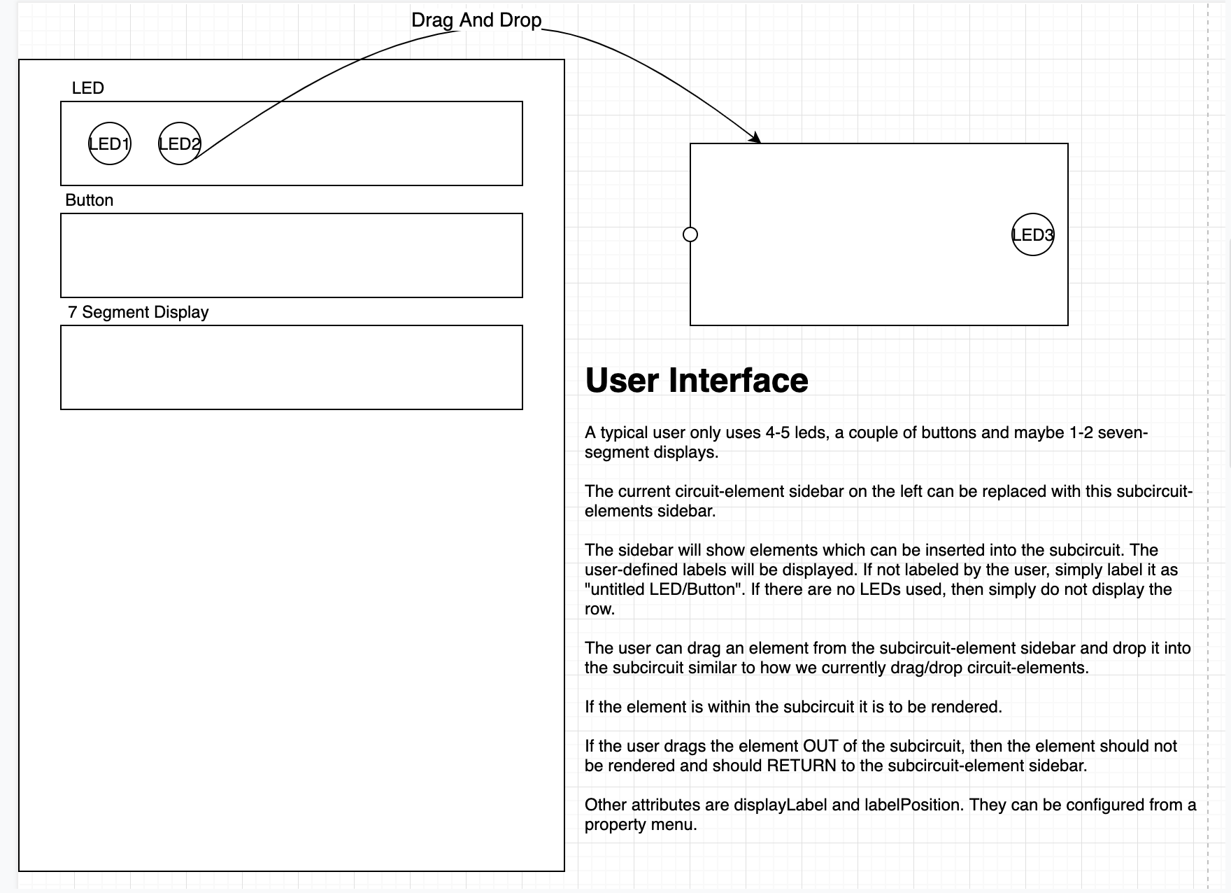
I think this is the best UI possible but might be tricky to implement.
@fpintos any inputs on this?
satu0king
on 26 May 2019
I like the way that looks! I think I mentioned something like this before, but the user should also be able to insert text, which could support either markdown or html, and maybe users could have some basic graphical options, like lines and boxes. Something similar could be implemented with the current text tool.
blane1257
on 26 May 2019
I like the way that looks! I think I mentioned something like this before, but the user should also be able to insert text, which could support either markdown or html, and maybe users could have some basic graphical options, like lines and boxes. Something similar could be implemented with the current text tool.
Yes I agree. The current text tool should be extended to be a full-fledged markdown based text editor. However, I don't think the subcircuit text tool needs to be this complicated, it is expected to be used only for annotation.
maybe users could have some basic graphical options, like lines and boxes
Yes this could be useful.
satu0king
on 26 May 2019
I like the way that looks! I think I mentioned something like this before, but the user should also be able to insert text, which could support either markdown or html, and maybe users could have some basic graphical options, like lines and boxes. Something similar could be implemented with the current text tool.
Supporting markdown is a good idea, but let's treat this as a separate issue, least it feature-creeps into the sub-layout issue.
fpintos
on 27 May 2019
No activity on this issue for a prolonged duration, will be closed if no further activities in next 7 days
![github-actions[bot] picture](https://avatars.githubusercontent.com/in/15368?v=4&s=40) github-actions[bot]
on 10 Mar 2020
github-actions[bot]
on 10 Mar 2020
Do not close
satu0king
on 11 Mar 2020
Related issues
 eKuG
·
7Comments
jbox144
·
7Comments
eKuG
·
7Comments
jbox144
·
7Comments
 tachyons
·
7Comments
satu0king
·
5Comments
tachyons
·
6Comments
tachyons
·
7Comments
satu0king
·
5Comments
tachyons
·
6Comments
Most helpful comment
I would like to look at this from a user experience point of view before we go forward with any implementation.
How does the user build the IC layout?
I see two approaches:
For now, let's concentrate on (1), since it is what we have today.
In Circuit-First, how does the circuit designer chooses which elements show up in IC layout?
There are 3 types of elements to consider:
(1) and (2) are trivial. (3) is what we're trying to solve in this issue. The key point is that such elements can be optionally included in the layout.
To me, if something is optional it means you don't have to think about it until you need it.
In the _circuit-first_ user experience this translates to two requirements:
Using a single LED as an example:
With these in mind, there are two ways to implement these requirements:
Given the user experience requirements above, I'm inclined to use the first approach, of extending the base class. I think using derived classes in this case will make it a lot more complicated to keep the UI simple.
All that being said, I'm open to head different approaches around how the user interface of this feature should work.