Apparently the point zero is taken as the left up corner of the screen instead of its center. "My Text" is where the cursor is and the yellow cube is the object using the coords.
Probably the World To Screen node also have this problem.
Test file: screen_to_world_issue.zip
Preview:

 knowledgenude
All 9 comments
Node _Screen To World_ - if you calculate the camera offset from the resulting vector, it works. At least in this example.
v.x = v.x - cam.transform.world.getLoc().x;
v.y = -(v.y - cam.transform.world.getLoc().y);

return v;
 e1e5en-gd
on 16 Sep 2020
e1e5en-gd
on 16 Sep 2020
@e1e5en-gd , i need more context about this. I am very noob :)
If this solve the issue maybe is better to just open a pr. I would like to just add some value to it, to correct the "offscreen", but there is also a problem when you rotate the camera along the Z axis
knowledgenude
on 17 Sep 2020
As a result of my discovery, I found, as it seems to me, the essence of the problem, and not its solution. For some reason, the conversion does not take into account the change in the position of the camera relative to the center of coordinates.
Maybe my find will help in solving, but I'm afraid to put on crutches.
e1e5en-gd
on 17 Sep 2020
I studied this topic a little and I have a question:
Based on your example, do you want that when transferring screen coordinates (0, 0), the object became at the origin of world coordinates (0, 0, 0)?
But that's not the purpose of the _ScreenToWorld_ node. You can do it like this:
The _ScreenToWorld_ task turns out that by passing the screen coordinates, you get this value in world (3D) coordinates at a certain distance. It turns out that the object is moving behind the cursor.
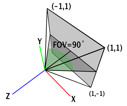
Based on the article and example it turns out that with a projection matrix, the boundaries of screen coordinates should be from -1 to 1, and the center (0, 0) is middle of the screen. Therefore, your example works correctly: you pass (0, 0) and get an object in the middle of the screen (relative to the camera at (0, 0, depth)).
And in order to be correct, you need to transform the coordinates of the cursor so that (0, 0) screen coordinates are in the center of the screen.
The conversion will be simple:
v1.x -= kha.System.windowWidth() / 2;
v1.y -= kha.System.windowHeight() / 2;
where _v1_ is a vector with screen coordinates.
But you need to take into account the distance to the object so that it does not go beyond the screen until the cursor leaves.
e1e5en-gd
on 23 Sep 2020
I just want that when the cursor is in the middle of the screen, the object using the coords is also in the middle of the camera.
Instead, it is in the middle of the camera just when the cursor is on the left up corner.
This is a wrong offset in my view, but i am not sure. Unfortunately i am not able to figure out too much, I have a lot of trouble trying to understand transforms. In some months i read it again :)
⁰
knowledgenude
on 23 Sep 2020
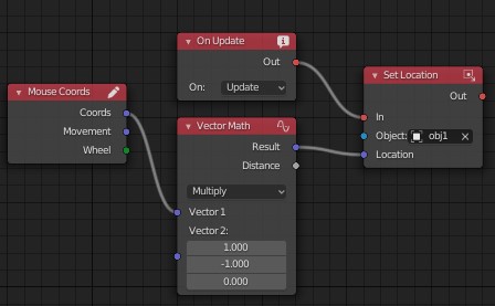
If we apply the transformation of the input screen coordinates (subtract half the width and height of the window), then we get the desired result: web-sample.
The interface displays the coordinates of the cursor, which we get from the MouseCoords node.
But this does not take into account the depth of the object. If we want the object to move within the screen, then we also need to do trigonometric transformations. Should it be added to the node (add a depth input parameter) or left to the user for development?
e1e5en-gd
on 24 Sep 2020
No, i think the user would not have nothing to do with this node except convert the coordinates.
The problem is that by adding or subtracting values, it will produces wrong coordinates (like in the example you send). When the cursor is in the middle, the object is also in the middle, but the rest is not correct (because the point zero is like the maximum height and 0 width) this would work only if the height and the width are proportional (0 both or maximum of both).
I think that the outputed coordinates should be like a "child" coordinates of the camera, this way, the point zero of X and Y always will be in the middle of the camera no matter its rotation or position. If you can do that, the next step is just convert the pixels information to vector, but i am just saying what i think, i don't have sure about nothing here.
knowledgenude
on 24 Sep 2020
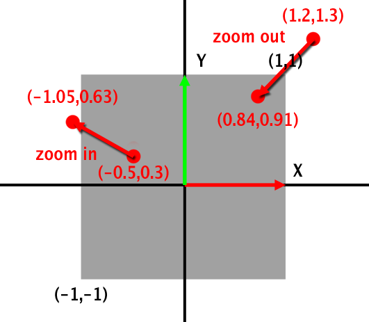
If you do not take into account the depth (the distance from the camera to the object), then this result is obtained. We get a point in 3D space in front of the camera itself, and in order for the object to move proportionally to the cursor, we need to take into account its distance from the camera for each object (to get the coefficient / "delay value" when moving from the cursor).
Therefore, you need to set the depth / distance or calculate it separately and convert the resulting values.
The direction (ray) will be calculated from two points: the first point of the camera (where we get it), the second at a certain distance.
These are my suggestions.
e1e5en-gd
on 24 Sep 2020
Oh sure, sorry i didn't had understand it before. Indeed, longer distance means longer coordinates. Your reasoning seems to be right for me.
knowledgenude
on 24 Sep 2020
Related issues
 Amir-Arsalan
·
4Comments
knowledgenude
·
3Comments
Amir-Arsalan
·
4Comments
knowledgenude
·
3Comments
 DevMagicLord
·
3Comments
DevMagicLord
·
3Comments
 Nos-
·
4Comments
Nos-
·
4Comments
 BrahRah
·
3Comments
BrahRah
·
3Comments