Zigbee2mqtt: Unable to flash CC2531
I'm following the guide Getting Started - having exactly the same parts, I'm unable to have both the CC Debugger and CC2531 to turn on when they are connected in the circuit as described. If I connect the CC Debugger and CC2531 indvidually they show up on the PC correctly. As soon as the downloader cable / BTool Programming Connector is in between, they both shut down (both lights are off).
Could some of the items be defective? Is there another way to flash the CC2531 with the current parts.
 tynor88
All 44 comments
show us a photo how you have connected / plugged all together
 HannesDi
on 22 Oct 2018
HannesDi
on 22 Oct 2018
@HannesDi sure, here you go. As you can see, no lights 👎

tynor88
on 22 Oct 2018
hmn ok.. looks like correct plugged directions for the cables...
have you tried another usb plugs like the rear ones? probally a usb power problem
or on a other pc?
HannesDi
on 22 Oct 2018
I tried on my laptop. Same issue. If I connect them individually they work fine and I see both in the Device Manager on Windows 10. That's why I'm thinking Its something with the BTool.
tynor88
on 22 Oct 2018
@tynor88 1. Try to press the "Reset" button on the debugger. Sometimes I need to make 2 or 3 retries.
- I hope BTool is a typo. We use Z-Tool to upload firmware.
 ptvoinfo
on 23 Oct 2018
ptvoinfo
on 23 Oct 2018
weird, why would you connect the cc2531 to computer when trying to flash it ? your debugger does power the cc2531 through the debug cable, doesn't it ?
 lolorc
on 23 Oct 2018
lolorc
on 23 Oct 2018
Did you try to plugin the connector on the cc2531 with the cable on the other side ? I needed to do this. have flashed 5 sticks like that
 FelixUster
on 23 Oct 2018
FelixUster
on 23 Oct 2018
I hade the same error the problem was the cc debuger driver that got installed automatic.
Did you try to install the driver manualy? 32bit version?
 JLFN
on 23 Oct 2018
JLFN
on 23 Oct 2018
weird, why would you connect the cc2531 to computer when trying to flash it ? your debugger does power the cc2531 through the debug cable, doesn't it ?
because: https://github.com/Koenkk/zigbee2mqtt/wiki/Getting-started
point 4; "Connect BOTH the CC2531 USB sniffer and the CC debugger to your PC using USB."
and i can confirm only when both is connected / powered the led turn from red to green
so: NO the debugger does not power the cc2531 trough the debug cable
HannesDi
on 23 Oct 2018
I've tried everything and as soon as the Downloader connector goes in between, both the CC Debugger and Zigbee USB sniffer turns off.
tynor88
on 23 Oct 2018
Hmm, I was looking at pictures and from what I can see I received this Downloader Connector:

Rather than this:
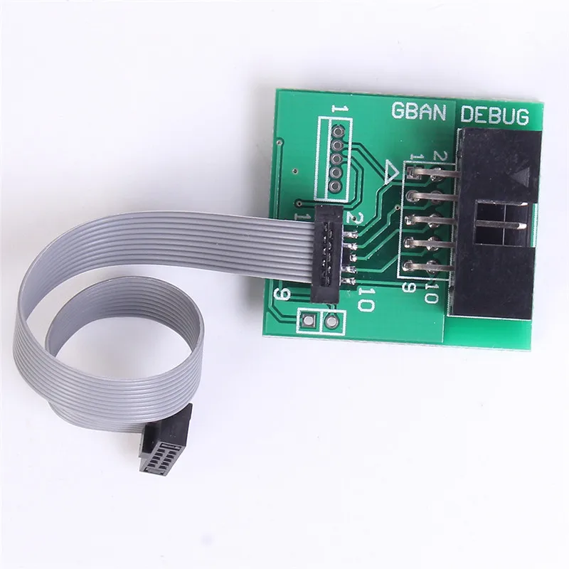
Are there any differences? Everybody is linking to the last one, but for some reason the sender from AliExpress sent me the first one (even though the pictures stated differently). I don't have the "CBAN DEBUG" in the top right corner and it looks a little bit smaller.
tynor88
on 23 Oct 2018
Can you post a picture of your board without the cable attached to it?
 Koenkk
on 23 Oct 2018
Koenkk
on 23 Oct 2018
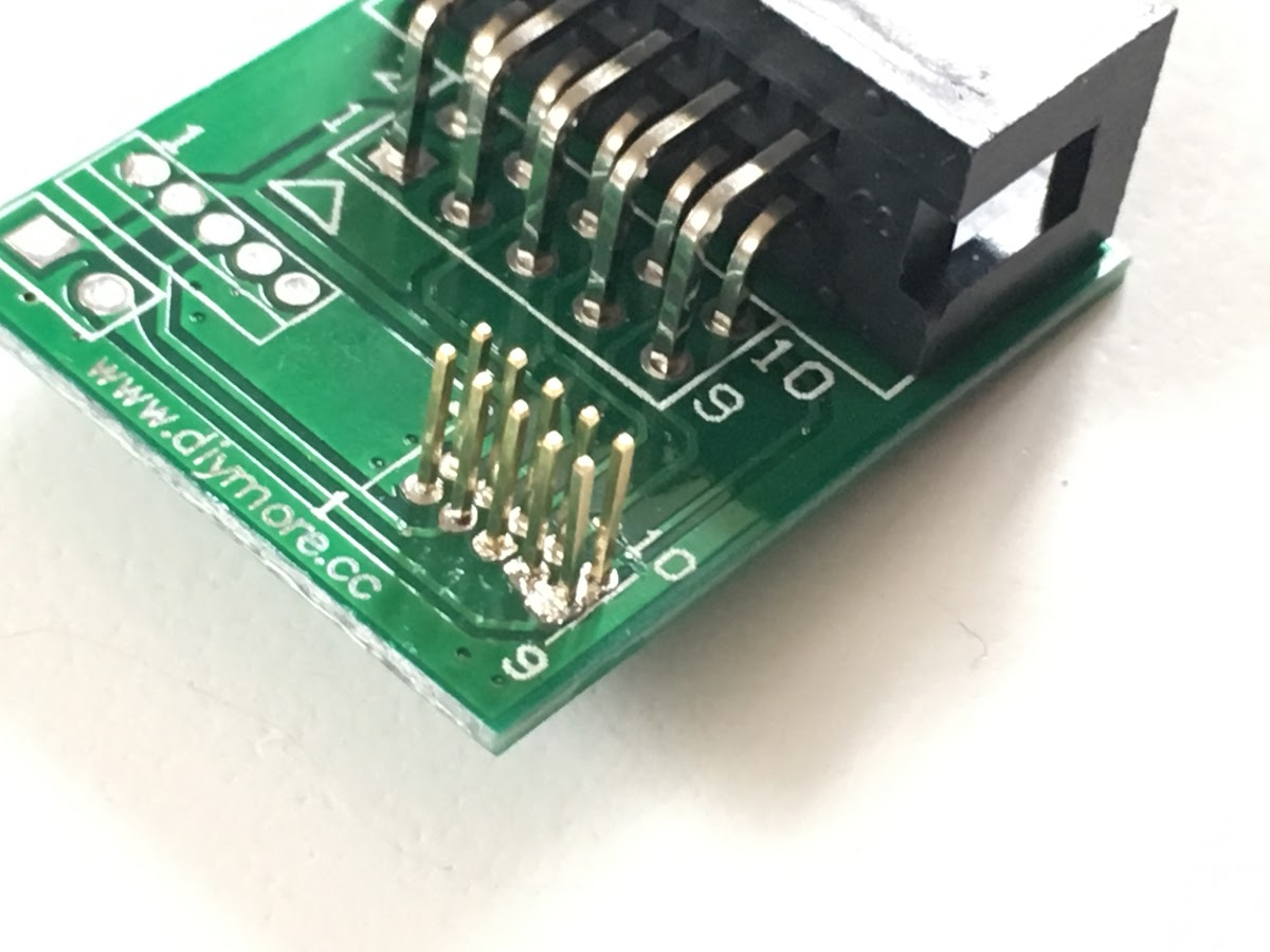
@Koenkk sure here you go:

tynor88
on 23 Oct 2018
Board seems to be fine, my guess it that either your CC debugger or sniffer is defective.
Koenkk
on 24 Oct 2018
But if I connect them without the board in the circuit, they both show up on Windows and drivers get installed correctly. So do you still think that is the case?
tynor88
on 24 Oct 2018
Can you try to connect the pins directly by using jumper wires? (so that you don't need the flat cable/connector board)
Koenkk
on 24 Oct 2018
@Koenkk i tried what you suggested with jumper wires. Result is:
If i connect the CCDebugger with the connector board: CC Debugger turns off (lights)
If i connect the Zigbee Sniffer with the connector board: Zigbee sniffer turns off (lights)
If i connect them in a circuit, both of them turns off as soon as the connector board goes in between.
tynor88
on 24 Oct 2018
@Koenkk sure here you go:
Is there a connection from the middle down pin to the big pad down right in the picture, it seems so and if i'm correct that if false.
 BudBundi
on 24 Oct 2018
BudBundi
on 24 Oct 2018
@tynor88
Maybe have a look at https://github.com/Koenkk/zigbee2mqtt/wiki/Alternative-firmware-flashing-methods if you have an Arduino laying around.
This way you could test if your CC2531 is ok.
If you have a multimeter you could test if all the pins on the connectors are wired correctly. Verify if all the Pins on the small connector match the big connector.
 pixeldoc2000
on 24 Oct 2018
pixeldoc2000
on 24 Oct 2018
If you have a NodeMCU laying around that would work too. I had trouble getting this to work so I documented my eventual set up as a comment over here..
 ericstewart22
on 28 Oct 2018
ericstewart22
on 28 Oct 2018
I had an identical problem when I tried flashing for the first time after all components arrived from Aliexpress. Turns out that the problem in my setup was the downloader cable. The 10 pin header was not correctly soldered, and a tiny amount of solder short circuited two pins. This tiny amount was only visible after removing the plastic separator.
I would suggest checking the pin header with a multimeter to make sure that each pin is not linked to another one.
 UnrealKazu
on 30 Oct 2018
UnrealKazu
on 30 Oct 2018
I had an identical problem when I tried flashing for the first time after all components arrived from Aliexpress. Turns out that the problem in my setup was the downloader cable. The 10 pin header was not correctly soldered, and a tiny amount of solder short circuited two pins. This tiny amount was only visible after removing the plastic separator.
I would suggest checking the pin header with a multimeter to make sure that each pin is not linked to another one.
Based on this reply ended up ordering another downloader board + cable, and it was indeed the problem. After i received a new one, everything worked perfectly.
Thanks for all the replies in here.
tynor88
on 7 Nov 2018
@tynor88 thanks for reporting back!
Koenkk
on 7 Nov 2018
For your information, I had the same issue. I've ordered all the needed hardware from Aliexpress. But when connecting the USB dongle to the CC Debugger using the downloader cable, it was not recognized (the led of the CC Debugger stays red). The problem was that 5 pins of the 10 pins header were short circuited. It even broke my CC Debugger.
I've ordered a new CC Debugger and a new downloader cable. Now everything is working fine...
 Largo2005
on 15 Dec 2018
Largo2005
on 15 Dec 2018
I had an identical problem when I tried flashing for the first time after all components arrived from Aliexpress. Turns out that the problem in my setup was the downloader cable. The 10 pin header was not correctly soldered, and a tiny amount of solder short circuited two pins. This tiny amount was only visible after removing the plastic separator.
I would suggest checking the pin header with a multimeter to make sure that each pin is not linked to another one.
Same problem also for me. I cleaned up the pins/circuit board and after a reset the green light showed up. Thanks UnrealKazu
 chriskgr
on 31 Mar 2019
chriskgr
on 31 Mar 2019
I had an identical problem when I tried flashing for the first time after all components arrived from Aliexpress. Turns out that the problem in my setup was the downloader cable. The 10 pin header was not correctly soldered, and a tiny amount of solder short circuited two pins. This tiny amount was only visible after removing the plastic separator.
I would suggest checking the pin header with a multimeter to make sure that each pin is not linked to another one.Same problem also for me. I cleaned up the pins/circuit board and after a reset the green light showed up. Thanks UnrealKazu
How did you clean the downloader cable board?
Tnx for the information
 j360b
on 2 May 2019
j360b
on 2 May 2019
I took out the excessive solder from the board and pins and then cleaned it with alcohol. Hope it helps.
Στις 2 Μαΐ 2019 19:57, ο χρήστης j360b notifications@github.com έγραψε:
I had an identical problem when I tried flashing for the first time after all components arrived from Aliexpress. Turns out that the problem in my setup was the downloader cable. The 10 pin header was not correctly soldered, and a tiny amount of solder short circuited two pins. This tiny amount was only visible after removing the plastic separator.
I would suggest checking the pin header with a multimeter to make sure that each pin is not linked to another one.
Same problem also for me. I cleaned up the pins/circuit board and after a reset the green light showed up. Thanks UnrealKazu
How did you clean the downloader cable board?
Tnx for the information
—
You are receiving this because you commented.
Reply to this email directly, view it on GitHubhttps://github.com/Koenkk/zigbee2mqtt/issues/527#issuecomment-488770533, or mute the threadhttps://github.com/notifications/unsubscribe-auth/ALWW23VUJ67UOZ5FWQSCGOTPTMTSDANCNFSM4F6OYRYQ.
chriskgr
on 2 May 2019
I was having similar problems and discovered that Pin 8, 9 and 10 were all shorted.
 RegularBloke
on 28 Jul 2019
RegularBloke
on 28 Jul 2019
Fixed it by buying a new connector from gban.cn.
The diymore.cc connector was broken/solden incorrectly for me too.
j360b
on 3 Aug 2019
I had the same problem. For me the issue was the fine pitch ribbon cable that came with the set from aliexpress. One of the 10 lines had no continuity (measured from the solder pads on the adapter board to the solder pads on the dongle). And of course it was the only one that couldn't be "fixed" by plugging in the connectors rotated by 180° on both ends, because it was the reset pin in one orientation and the DD (debug data) pin in the other orientation. (what I read only 4 out of the 10 pins are necessary when flashing)
The cable worked after I squeezed both ribbon connectors in a vice. It looks like one of the knife contacts in the connectors hadn't made contact to the copper in the ribbon. Visually the connectors were correctly seated even before that.
The adapter board is one of the "diymore" btw. The soldering looked fine on it, although I only checked after I read this thread when the flashing didn't work. I guess I was very lucky since it seems that in some cases the bad soldering job can even kill the programmer.
 LupinIII
on 6 Nov 2019
LupinIII
on 6 Nov 2019
My debugger light is also always red. Can I buy all of these parts from someone like Texas Instruments instead of AliExpress so that they're more likely to work?
 NodeGuy
on 29 Nov 2019
NodeGuy
on 29 Nov 2019
@NodeGuy
My debugger light is also always red.
Did you try to press the Reset Button on the Debugger (multiple) times with CC2531 connected?
Did you connect the CC2531 AND the CCDebugger with USB?
Did you check the Ribbon Cable and Adapter PCB for correctly wiring, shorts and bad solder joints?
You can buy the stuff from TI, but it will cost a small fortune.
You can buy CC2531 preprogramed on eBay (at least in Germany).
You can try to flash the CC2531 with Arduino or ESP.
pixeldoc2000
on 1 Dec 2019
Thank you for your suggestions. I tried pressing the Reset Button multiple times and made sure both devices were connected via USB. I visually inspected all the parts but didn't take the time to investigate shorts or bad solder joints.
What I did instead is buy the CC-DEBUGGER directly from Texas Instruments for $49. It came with higher-quality components sealed in an anti-static bag and worked on the first try. Paying an extra $33 over what I gave AliExpress was worth the time savings and peace of mind for me.
@Koenkk how about we add the above option to the documentation as an alternative source for people who want to trade more money for reduced risk?
NodeGuy
on 8 Dec 2019
Paying $49 for a CC-DEBUGGER is not worth it, for that money you can buy a CC26X2R1 (https://www.zigbee2mqtt.io/information/supported_adapters.html)
Koenkk
on 9 Dec 2019
Oh sure, now he tells me! 😉
Thanks for pointing out that page; I hadn't seen it before. It would be helpful to add a link to it from the What do I need? page.
After some digging on the TI website it looks like this would be the best option for me:
 SimpleLink™ multi band CC1352R wireless MCU Launchpad™ SensorTag kit
Is it compatible with your project?
NodeGuy
on 10 Dec 2019
I don't know about that one. I would recommend buying one off https://www.zigbee2mqtt.io/information/supported_adapters.html a link can be found after Can be bought via ...
Koenkk
on 11 Dec 2019
Ah, thank you. After exploring your https://github.com/Koenkk/Z-Stack-firmware I see that a) you've done a lot of amazing work on this (thank you!) and b) the CC26X2R1 firmware is not ready for production yet so I'll try the CC2531 for now.
NodeGuy
on 12 Dec 2019
CC26X2R1 firmware is ready for production (forgot to update docs), thanks for mentioning.
Koenkk
on 12 Dec 2019
@NodeGuy @Koenkk
After some digging on the TI website it looks like this would be the best option for me:
SimpleLink™ multi band CC1352R wireless MCU Launchpad™ SensorTag kit
This looks like a pretty nice device compete with case and external antenna. Much better than a bare dev board like CC2531 or CC26X2R1 ;-)
Anyway, i'm still quite happy with my GBAN Zigbee Dongle and Z2M.
@Koenkk
Why is the GBAN Zigbee Dongle removed from https://www.zigbee2mqtt.io/information/supported_adapters.html ?
pixeldoc2000
on 12 Dec 2019
It has been merged with the CC2530 (as it is basically the same device and is still mentioned Can be bought on e.g. AliExpress: CC2530, CC2530 + CC2591, GBAN GB2530)
Koenkk
on 13 Dec 2019
I had an identical problem when I tried flashing for the first time after all components arrived from Aliexpress. Turns out that the problem in my setup was the downloader cable. The 10 pin header was not correctly soldered, and a tiny amount of solder short circuited two pins. This tiny amount was only visible after removing the plastic separator.
I would suggest checking the pin header with a multimeter to make sure that each pin is not linked to another one.
Thank you so much.
I had the same problem. I fixed my board by scratching the soldering between the pin on the back of the board.
 OPolpo
on 22 Dec 2019
OPolpo
on 22 Dec 2019
Another way to fix the "no green light" problem. I didn't push hard enough to actually connect the cable between the CC and the Downloader Connector. The cable works only when the board pins pierce the tiny cables. I just plugged it in being a bit too tender.
 burningTyger
on 19 Mar 2020
burningTyger
on 19 Mar 2020
Is this CC1352R linked above supported by zigbee2mqtt? It's not on the supported adapters page.
 Ramblurr
on 5 Apr 2020
Ramblurr
on 5 Apr 2020
I had an identical problem when I tried flashing for the first time after all components arrived from Aliexpress. Turns out that the problem in my setup was the downloader cable. The 10 pin header was not correctly soldered, and a tiny amount of solder short circuited two pins. This tiny amount was only visible after removing the plastic separator.
I would suggest checking the pin header with a multimeter to make sure that each pin is not linked to another one.
I had exactly the same issue. The little board connecting the two flat cables was short circuiting two pins. Fixed the poor soldering quality and it worked. So check carefully!
(Unfortunately this was after I ordered a new debugger, as I thought that one was broken :-(.... )
 wouzer
on 6 Apr 2020
wouzer
on 6 Apr 2020
Related issues
 jeroenterheerdt
·
3Comments
jeroenterheerdt
·
3Comments
 z4rn0x
·
3Comments
z4rn0x
·
3Comments
 ophilips
·
4Comments
ophilips
·
4Comments
 tb-killa
·
3Comments
tb-killa
·
3Comments
 Courty40
·
4Comments
Courty40
·
4Comments
Most helpful comment
I had an identical problem when I tried flashing for the first time after all components arrived from Aliexpress. Turns out that the problem in my setup was the downloader cable. The 10 pin header was not correctly soldered, and a tiny amount of solder short circuited two pins. This tiny amount was only visible after removing the plastic separator.
I would suggest checking the pin header with a multimeter to make sure that each pin is not linked to another one.