Zephyr: k_uptime_delta returns wrong times
I like to detect button events. They are selected after different holding times for a button.
A gpio interrupt is generated at every change of the button pin state. At the interrupt handler the time difference is measured between the current and the previous interrupt.
For that k_uptime_delta is used. I recognized that my measured times are at least by the factor 2 to low.
My setup is a own stm32F412 board with following config:
CONFIG_SYS_CLOCK_HW_CYCLES_PER_SEC=96000000
CONFIG_SYS_CLOCK_TICKS_PER_SEC=1000

# clock configuration
CONFIG_CLOCK_CONTROL=y

# Clock configuration for Cube Clock control driver
CONFIG_CLOCK_STM32_HSE_CLOCK=24000000
CONFIG_CLOCK_STM32_SYSCLK_SRC_PLL=y

# use HSE as PLL input
CONFIG_CLOCK_STM32_PLL_SRC_HSE=y

# the board have an external oscillator
CONFIG_CLOCK_STM32_HSE_BYPASS=n

# produce 96MHz clock at PLL output
CONFIG_CLOCK_STM32_PLL_M_DIVISOR=12
CONFIG_CLOCK_STM32_PLL_N_MULTIPLIER=96
CONFIG_CLOCK_STM32_PLL_P_DIVISOR=2
CONFIG_CLOCK_STM32_PLL_Q_DIVISOR=4

CONFIG_CLOCK_STM32_AHB_PRESCALER=2
CONFIG_CLOCK_STM32_APB1_PRESCALER=4
CONFIG_CLOCK_STM32_APB2_PRESCALER=4
Maybe I setup the config wrongly or the k_uptime_delta function is buggy. Any ideas?
 StefJar
All 33 comments
CC @andyross
 aescolar
on 1 Jul 2019
aescolar
on 1 Jul 2019
cc @pizi-nordic
 ioannisg
on 1 Jul 2019
ioannisg
on 1 Jul 2019
Can you post the code and timings you're getting, and what exactly you expect? The uptime delta gadget is very simple. Do you see similar skew with things like k_sleep() (which would imply that the clock is wrong)? Or maybe you're expecting more precision than the ~1ms tick rate you have configured can provide?
 andyross
on 2 Jul 2019
andyross
on 2 Jul 2019
hopefully I got everything in that code snip:
```
/*
- main2.c
* - Created on: 3 Jul 2019
- Author: stefan
*/
include
include
include
include
include
include
include
include
include
include
include
LOG_MODULE_REGISTER(MAIN, LOG_LEVEL_APP_MAIN);
// ======================= gpio ==============
typedef enum gpio_errors {
gpio_error_success = 0,
gpio_error_gpio_notfound = 1,
} gpio_error_t;
gpio_error_t gpio_init(void);
// external implementations
void gpio_event_button_power(uint32_t pinState);
void gpio_event_button_action(uint32_t pinState);
unsigned int gpio_get_powerButton_state(void);
unsigned int gpio_get_actionButton_state(void);
// gpio events are mapped to events detected by the External interrupt/event controller (EXTI)
// this controller has 23 edge detectors
// PA0, PB0, ... PD0 are mapped to line 0
// PA1, PB1, ... PD1 are mapped to line 1
// ...
// PA12, PB12, ... PD12 are mapped to line 12
//! enum holding unique ids for the gpio pins
enum eExtIntrLines {
eExtIntrLine_powerButton = 0, // PC0
eExtIntrLine_actionButton = 12, // PB12
eGPIOeintID_max = 23
};
// setup
// ext interrupt controller
// PA0 - PH0 -> ext intr 0
// PA1 - PH1 -> ext intr 1
// ...
// PA15 - PH15 -> ext intr 15
//
// our setup:
// C0 -> EXTI0 (power on button)
// B12 -> EXTI12 (action button)
//
// zephyr gipo callback struct
// A8 -> gpioA
// B4 & B12 -> gpioB
// C0 & C8 -> gpioC
define BUTTON_POWER gpio.C,0
define BUTTON_ACTION gpio.B,12
typedef struct gpio_s {
struct device * A;
struct device * B;
struct device * C;
struct gpio_callback gpio_cb_A;
struct gpio_callback gpio_cb_B;
struct gpio_callback gpio_cb_C;
} gpio_t;
static gpio_t gpio;
static void gpio_cb_gpioB (struct device *dev, struct gpio_callback *cb, u32_t pins) {
(void) dev;
(void) cb;
// B12 is high
if (pins & BIT(eExtIntrLine_actionButton)) {
uint32_t v;
gpio_pin_read(BUTTON_ACTION, &v);
gpio_event_button_action(v);
}
}
static void gpio_cb_gpioC (struct device *dev, struct gpio_callback *cb, u32_t pins) {
(void) dev;
(void) cb;
// C0 is high
if (pins & BIT(eExtIntrLine_powerButton)) {
uint32_t v;
gpio_pin_read(BUTTON_POWER, &v);
gpio_event_button_power(v);
}
}
gpio_error_t gpio_init(void) {
LOG_INF("init gpios");
memset(&gpio, 0, sizeof(gpio));

LOG_DBG("get gpio bindings");
gpio.A = device_get_binding("GPIOA");
if (NULL == gpio.A) {
    LOG_ERR("GPIOA not found");
    return gpio_error_gpio_notfound;
}

gpio.B = device_get_binding("GPIOB");
if (NULL == gpio.B) {
    LOG_ERR("GPIOB not found");
    return gpio_error_gpio_notfound;
}

gpio.C = device_get_binding("GPIOC");
if (NULL == gpio.C) {
    LOG_ERR("GPIOC not found");
    return gpio_error_gpio_notfound;
}

LOG_DBG("init callbacks");
gpio_init_callback(&gpio.gpio_cb_B, gpio_cb_gpioB, BIT(eExtIntrLine_actionButton));
gpio_init_callback(&gpio.gpio_cb_C, gpio_cb_gpioC, BIT(eExtIntrLine_powerButton));

gpio_add_callback(gpio.B, &gpio.gpio_cb_B);
gpio_add_callback(gpio.C, &gpio.gpio_cb_C);

LOG_DBG("configure pins");

gpio_pin_configure(BUTTON_POWER,
    GPIO_DIR_IN | // input
    GPIO_INT | // interrupt
    GPIO_PUD_PULL_UP | // pull up
    GPIO_INT_DEBOUNCE | // debounce pin
    GPIO_INT_EDGE | // edge detection
    GPIO_INT_DOUBLE_EDGE // up and down
);

gpio_pin_configure(BUTTON_ACTION,
    GPIO_DIR_IN | // input
    GPIO_INT | // interrupt
    GPIO_PUD_PULL_UP | // pull up
    GPIO_INT_DEBOUNCE | // debounce pin
    GPIO_INT_EDGE | // edge detection
    GPIO_INT_DOUBLE_EDGE
);

LOG_DBG("enable callbacks");

gpio_pin_enable_callback(BUTTON_POWER);
gpio_pin_enable_callback(BUTTON_ACTION);

return gpio_error_success;
}
unsigned int gpio_get_powerButton_state(void) {
u32_t v;
gpio_pin_read(BUTTON_POWER, &v);
return v == 1 ? 1 : 0;
}
unsigned int gpio_get_actionButton_state(void) {
u32_t v;
gpio_pin_read(BUTTON_ACTION, &v);
return v == 1 ? 1 : 0;
}
// ======================= button ==============
define BUTTON_50MS (50)
define BUTTON_1SEC (1000)
define BUTTON_3SEC (3000)
define BUTTON_5SEC (5000)
define BUTTON_CLICK_INTERVAL (250)
typedef enum button_states {
button_state_pressed = 0,
button_state_released = 1,
} button_state_t;
typedef enum button_events {
button_event_none = 0,
button_event_lowHigh = 1,
button_event_highLow = 2,
} button_event_t;
typedef struct button_sm {
s64_t ts; // time stamp of the latest action button
button_state_t s; // state of the action button
uint32_t lpv; // last pin value
} button_sm_t;
typedef struct button_sm_event {
button_event_t ev; // event
unsigned int t; // up or low time of the pin
} button_sm_event_t;
typedef struct button {
button_sm_t ab; // action button
unsigned int ab_click_c; // action button click counter
struct k_timer ab_timer;
button_sm_t pb; // power button
unsigned int pb_click_c; // power button click counter
struct k_timer pb_timer;

struct k_timer reset_timer; // timer of the reset state
unsigned int reset_state;
} button_t;
static button_t button;
static void button_sm_init(button_sm_t * b, const uint32_t pinVal) {
b->s = 0 == pinVal ? button_state_pressed : button_state_released;
b->lpv = pinVal;
b->ts = k_uptime_get();
}
static void button_sm_process(button_sm_t * b, const uint32_t pinVal, button_sm_event_t * e) {
e->ev = button_event_none;
if (0 == pinVal) {
// button is pressed
if (b->s == button_state_released) {
e->ev = button_event_highLow;
}
} else {
// pin is low and before it was high
if (b->s == button_state_pressed) {
e->ev = button_event_lowHigh;
}
}
if (button_event_none == e->ev) {
e->t = 0;
} else {
s64_t delta;
// get the difference and set ts with the latest time
delta = k_uptime_delta(&(b->ts));
e->t = (unsigned int) delta;
}
b->s = 0 == pinVal ? button_state_pressed : button_state_released;
}
static void button_power_timer(struct k_timer *timer_id) {
LOG_DBG("power button clicks %u", button.pb_click_c);
switch (button.pb_click_c) {
case 1:
LOG_INF("button power single click event");
break;
case 2:
LOG_INF("button power double click event");
break;
default:
LOG_DBG("no event associated with %u clicks", button.pb_click_c);
}
button.pb_click_c = 0;
}
static void button_action_timer(struct k_timer *timer_id) {
LOG_DBG("action button clicks %u", button.ab_click_c);
switch (button.ab_click_c) {
case 1:
LOG_INF("button action single click event");
break;
case 2:
LOG_INF("button action double click event");
break;
case 3:
LOG_INF("button power triple click event");
break;
default:
LOG_DBG("no event associated with %u clicks", button.ab_click_c);
}
button.ab_click_c = 0;
}
static void button_reset_timer(struct k_timer *timer_id) {
LOG_DBG("reset state 0x%X", button.reset_state);
if (0x3 == button.reset_state) {
        LOG_INF("button power+ button reset event");
}
button.reset_state = 0;
}
void gpio_event_button_power(uint32_t pinState) {
button_sm_event_t ev;
button_sm_process(&button.pb, pinState, &ev);
if (button_event_lowHigh == ev.ev) {
    LOG_DBG("T=%u", ev.t);
    // 5sec check
    if ((ev.t > BUTTON_5SEC) && (ev.t < (BUTTON_5SEC + BUTTON_1SEC))) {
        LOG_DBG("power button reset detected");
        button.reset_state |= 0x1;
        k_timer_start(&button.reset_timer, K_MSEC(100), 0);
    } else if (ev.t > BUTTON_1SEC) {
        LOG_DBG("power button power off detected");
    } else if ((ev.t > BUTTON_50MS) && (ev.t < (BUTTON_50MS+BUTTON_CLICK_INTERVAL))){
        button.pb_click_c++;
        // start timer that expires if we didn't get another click
        k_timer_start(&button.pb_timer, K_MSEC(BUTTON_CLICK_INTERVAL), 0);
    }
}
}
void gpio_event_button_action(uint32_t pinState) {
button_sm_event_t ev;
button_sm_process(&button.ab, pinState, &ev);
if (button_event_lowHigh == ev.ev) {
    LOG_DBG("T=%u", ev.t);
    // 5sec check
    if ((ev.t > BUTTON_5SEC) && (ev.t < (BUTTON_5SEC + BUTTON_1SEC))) {
        LOG_DBG("action button reset detected");
        button.reset_state |= 0x2;
        k_timer_start(&button.reset_timer, K_MSEC(100), 0);
    } else if ((ev.t > BUTTON_3SEC) && (ev.t < (BUTTON_3SEC + BUTTON_1SEC))) {
        LOG_DBG("action button discover detected");
    } else if ((ev.t > BUTTON_50MS) && (ev.t < (BUTTON_50MS+BUTTON_CLICK_INTERVAL))){
        button.ab_click_c++;
        // start timer that expires if we didn't get another click
        k_timer_start(&button.ab_timer, K_MSEC(BUTTON_CLICK_INTERVAL), 0);
    }
}
}
void button_init(void) {
LOG_DBG("init button");
memset(&button, 0, sizeof(button));
button_sm_init(&button.pb, gpio_get_powerButton_state());
button_sm_init(&button.ab, gpio_get_actionButton_state());
k_timer_init(&button.pb_timer, button_power_timer, NULL);
k_timer_init(&button.ab_timer, button_action_timer, NULL);
k_timer_init(&button.reset_timer, button_reset_timer, NULL);
}
// ==================== main ==============================
void main(void)
{
gpio_init();
button_init();
k_cpu_idle();
}
```
use a stm32f412 dev board. The pins C0 and B12 are used as buttons.
StefJar
on 3 Jul 2019
Could you please confirm that value returned by sys_clock_hw_cycles_per_sec() is correct on your platform?
Could you please tell me what value is returned by sys_clock_hw_cycles_per_tick()?
 pizi-nordic
on 11 Jul 2019
pizi-nordic
on 11 Jul 2019
I added some lines to my code and got following result
[00:00:00.155,000] <dbg> MAIN.main_test: sys_clock_hw_cycles_per_sec = 96000000
[00:00:00.159,000] <dbg> MAIN.main_test: sys_clock_hw_cycles_per_tick = 9600
Can you post the code and timings you're getting, and what exactly you expect? The uptime delta gadget is very simple. Do you see similar skew with things like k_sleep() (which would imply that the clock is wrong)? Or maybe you're expecting more precision than the ~1ms tick rate you have configured can provide?
Think 1ms resolution is good enough to detect human interaction on buttons ;).
I am not activating the RTC driver, which should give in general a good resolution. Because it does not bring the possibility to set it's date & time. I wrote an own implementation, for the RTC so I can setup it's date & time and use it for more precise datetime stamping(for sensors etc.)
StefJar
on 12 Jul 2019
Just edit hello_world and add a loop like:
for(int sec=0; sec<120; sec++) {
    printk("%ds...\n", sec);
    k_sleep(1000);
}
And run it and compare with a stopwatch. Is the machine clock correct?
andyross
on 12 Jul 2019
I done the measurment:
after 60sec the watch showed 2min
and after 120sec the showed 4min
I runed the test with
CONFIG_TRACING_CPU_STATS=y
CONFIG_TRACING_CPU_STATS_LOG=y
to make show that there is nothing else running.

CPU usage: 0

CPU usage: 0

[00:00:33.855,000] <dbg> BUTTON.gpio_event_button_power: T=102

CPU usage: 1

[00:00:34.108,000] <dbg> BUTTON.button_power_timer: power button clicks 1

[00:00:34.111,000] <dbg> CEP.cep_processEvent_button: battery status

[00:00:34.115,000] <dbg> MAIN.main_test: sys_clock_hw_cycles_per_sec = 96000000

[00:00:34.118,000] <dbg> MAIN.main_test: sys_clock_hw_cycles_per_tick = 9600

0s...

1s...

CPU usage: 1

2s...

3s...

CPU usage: 0

4s...

5s...

CPU usage: 0

6s...

7s...

CPU usage: 0

8s...

9s...

CPU usage: 0

10s...

11s...

CPU usage: 0

12s...

13s...

CPU usage: 0

14s...

15s...

CPU usage: 0

16s...

17s...

CPU usage: 0

18s...

19s...

CPU usage: 0

20s...

21s...

CPU usage: 0

22s...

23s...

CPU usage: 0

24s...

25s...

CPU usage: 0

26s...

27s...

CPU usage: 0

28s...

29s...

CPU usage: 0

30s...

31s...

CPU usage: 0

32s...

33s...

CPU usage: 0

34s...

35s...

CPU usage: 0

36s...

37s...

CPU usage: 0

38s...

39s...

CPU usage: 0

40s...

41s...

CPU usage: 0

42s...

43s...

CPU usage: 0

44s...

45s...

CPU usage: 0

46s...

47s...

CPU usage: 0

48s...

49s...

CPU usage: 0

50s...

51s...

CPU usage: 0

52s...

53s...

CPU usage: 0

54s...

55s...

CPU usage: 0

56s...

57s...

CPU usage: 0

58s...

59s...

CPU usage: 0

60s...

61s...

CPU usage: 0

62s...

63s...

CPU usage: 0

64s...

65s...

CPU usage: 0

66s...

67s...

CPU usage: 0

68s...

69s...

CPU usage: 0

70s...

71s...

CPU usage: 0

72s...

73s...

CPU usage: 0

74s...

75s...

CPU usage: 0

76s...

77s...

CPU usage: 0

78s...

79s...

CPU usage: 0

80s...

81s...

CPU usage: 0

82s...

83s...

CPU usage: 0

84s...

85s...

CPU usage: 0

86s...

87s...

CPU usage: 0

88s...

89s...

CPU usage: 0

90s...

91s...

CPU usage: 0

92s...

93s...

CPU usage: 0

94s...

95s...

CPU usage: 0

96s...

97s...

CPU usage: 0

98s...

99s...

CPU usage: 0

100s...

101s...

CPU usage: 0

102s...

103s...

CPU usage: 0

104s...

105s...

CPU usage: 0

106s...

107s...

CPU usage: 0

108s...

109s...

CPU usage: 0

110s...

111s...

CPU usage: 0

112s...

113s...

CPU usage: 0

114s...

115s...

CPU usage: 0

116s...

117s...

CPU usage: 0

118s...

119s...

CPU usage: 0

CPU usage: 0

CPU usage: 0

CPU usage: 0

CPU usage: 0

CPU usage: 0

CPU usage: 0
This is very strange. Are you sure that whole clock tree setup is correct? Could you please confirm the crystal oscillator frequency (measure it on the board)?
pizi-nordic
on 17 Jul 2019
I measured the two OSCs and they run on 24MHz and 32kHz.
I attached a screenshot how I tried to setup my board:
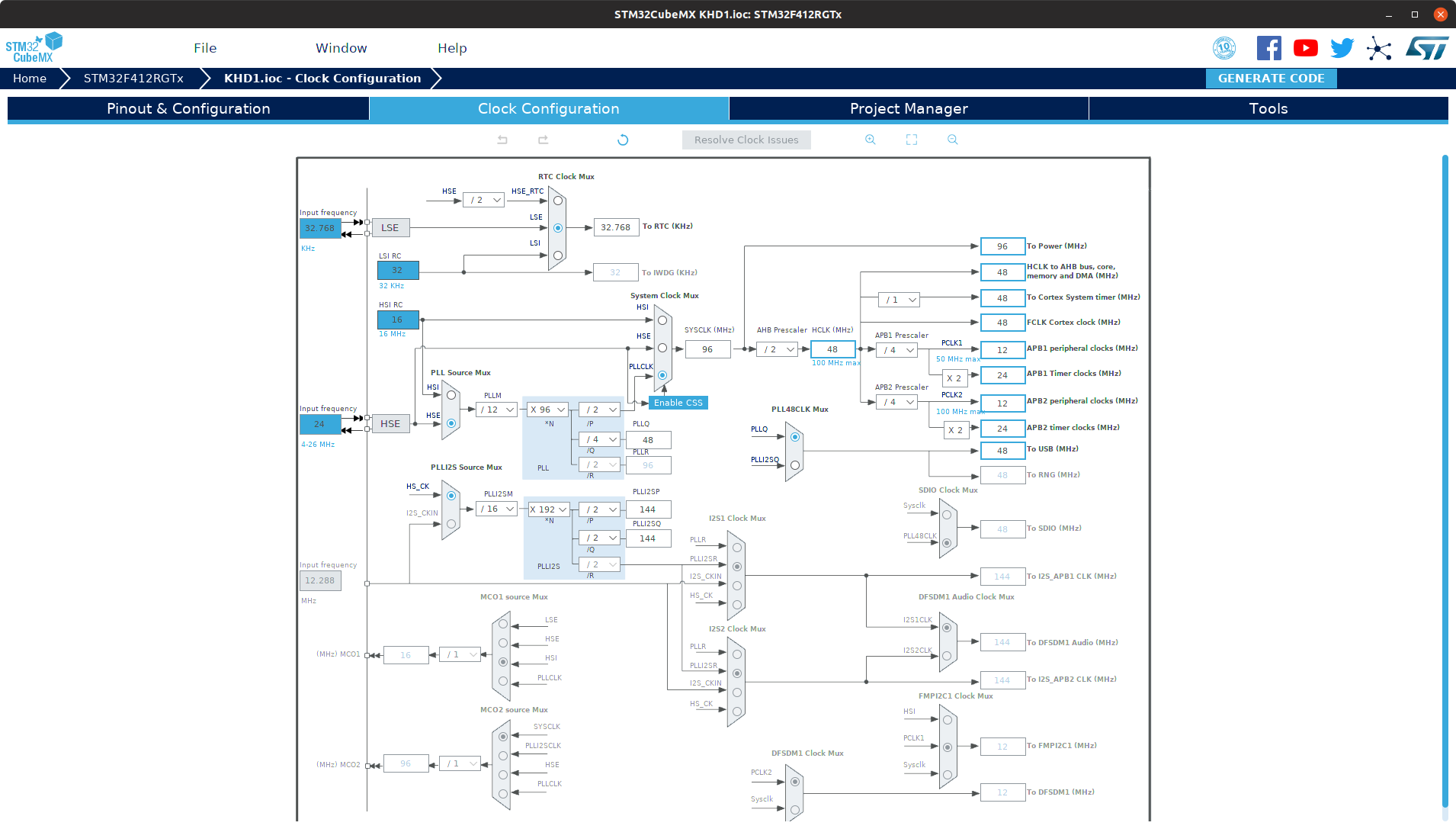
The SYSCLK is 96MHz but the Coretex System Timer is 48MHz. So maybe the
CONFIG_SYS_CLOCK_HW_CYCLES_PER_SEC=96000000
CONFIG_SYS_CLOCK_TICKS_PER_SEC=1000
conflicts with
CONFIG_CORTEX_M_SYSTICK
which is activated.
StefJar
on 18 Jul 2019
If the system timer is running at 48MHz, then the CONFIG_SYS_CLOCK_HW_CYCLES_PER_SEC should be set to 48000000.
pizi-nordic
on 18 Jul 2019
Ok I tried that but the error prevails.
What clk source is used for k_uptime_delta?
I quickly checked the documentation for systick (p 250)
http://infocenter.arm.com/help/topic/com.arm.doc.dui0553b/DUI0553.pdf
For me it looks like a 32Bit register. Is this directly mapped/refereed in k_uptime_delta?
StefJar
on 18 Jul 2019
@StefJar, I suspect there is an issue around core clock computation when CONFIG_CLOCK_STM32_AHB_PRESCALER is not 1.
Can you rework your configuration and test again using CONFIG_CLOCK_STM32_AHB_PRESCALER set to 1 ?
I expect something clos to the following would work:
CONFIG_CLOCK_STM32_AHB_PRESCALER=1
CONFIG_CLOCK_STM32_APB1_PRESCALER=8
CONFIG_CLOCK_STM32_APB2_PRESCALER=8
 erwango
on 24 Jul 2019
erwango
on 24 Jul 2019
I changed the cfg to
CONFIG_SYS_CLOCK_HW_CYCLES_PER_SEC=48000000
CONFIG_CLOCK_STM32_AHB_PRESCALER=1
CONFIG_CLOCK_STM32_APB1_PRESCALER=8
CONFIG_CLOCK_STM32_APB2_PRESCALER=8
The time problem is still happens.
On my system I have the RTC deactivated but using it through a own driver
and following things activated:
CONFIG_SYS_POWER_MANAGEMENT=y
# compile configs
CONFIG_DEBUG=y
CONFIG_DEBUG_OPTIMIZATIONS=y

# mcu usage metrics
CONFIG_TRACING_CPU_STATS=y
CONFIG_TRACING_CPU_STATS_LOG=y
maybe powersaving disables some clk
StefJar
on 24 Jul 2019
I changed the cfg to
CONFIG_SYS_CLOCK_HW_CYCLES_PER_SEC=48000000
You also need to update PLL settings in order to match the requested output freq.
erwango
on 24 Jul 2019
Dig in this a bit more.
k_uptime_get is based on cortex systick driver, which is based on CONFIG_SYS_CLOCK_HW_CYCLES_PER_SEC definition.
Problem is on STM32, cortex systick is ticked from HCLK, which is System Core clock / AHB prescaler.
It happens that AHB pre-scaler is always set to 1 for all STM32 boards, which explains this misalignment has never been detected. On your side, you're setting AHB prescaler to 2...
Following fix in drivers/timer/cortex_m_systick.c should fix your issue:
 #define CYC_PER_TICK (CONFIG_SYS_CLOCK_HW_CYCLES_PER_SEC   \
+             / CONFIG_CLOCK_STM32_AHB_PRESCALER \
              / CONFIG_SYS_CLOCK_TICKS_PER_SEC)
To be arranged for upstream of course.
erwango
on 26 Jul 2019
I can confirm that changing #define CYC_PER_TICK solves my problem.
thx @erwango and @pizi-nordic for the support
I leave it to @erwango close the issue when the fix gets merged
StefJar
on 26 Jul 2019
@StefJar, I'm looking on how to fix this issue and there is no easy solution as zephyr relies on SysTick as general system clock, while on STM32 there is difference between system clock (SYSCLK) and AHB clock which feeds Cortex SysTick.
This is similar to (some) other vendors solution, difference is they don't allow changing the master clock/core clock prescaler.
So, on STM32, fixing the SysTick calculation using AHB prescaler would introduce the risk of potential desynchro with other subsystem implemented in Zephyr with system tick (ie STM32 HCLK) while on STM32 it is actually using SYSCLK from HW point of view.
Safest solution would then be to forbid the change of AHB prescaler value and mandate it to be set to 1, as it is the value used on all STM32 boards upstream.
So here is my question: how did you come to use AHB prescaler value to 2. Would it be acceptable for you to:
- set a lower value to SYSCLK (divide by 2) or and keep APB prescalers
- keep SYSCLK value and set higher value to APB prescalers (multiple by 2)
These both solutions would get you to the same peripheral bus clocks AND allow to keep HCLK=SYSCLK
erwango
on 30 Jul 2019
good point
I am currently rebuilding an old firmware new on zephyr. That's why I didn't started with any demo board. I took a demo board as template and created my own board. For it's setup I used the old projects CubeMX template.
imho I think it is a bit confusing if you are using an STM std CubeMX tool to figure out the clk parameters and they are not compatible with Zephyr.
by setting:
# clock configuration
CONFIG_SYS_CLOCK_HW_CYCLES_PER_SEC=48000000

CONFIG_CLOCK_CONTROL=y

# Clock configuration for Cube Clock control driver
CONFIG_CLOCK_STM32_HSE_CLOCK=24000000
CONFIG_CLOCK_STM32_SYSCLK_SRC_PLL=y

# use HSE as PLL input
CONFIG_CLOCK_STM32_PLL_SRC_HSE=y

# the board have an external oscillator
CONFIG_CLOCK_STM32_HSE_BYPASS=n

# produce 96MHz clock at PLL output
CONFIG_CLOCK_STM32_PLL_M_DIVISOR=12
CONFIG_CLOCK_STM32_PLL_N_MULTIPLIER=96
CONFIG_CLOCK_STM32_PLL_P_DIVISOR=2
CONFIG_CLOCK_STM32_PLL_Q_DIVISOR=4

CONFIG_CLOCK_STM32_AHB_PRESCALER=1
CONFIG_CLOCK_STM32_APB1_PRESCALER=8
CONFIG_CLOCK_STM32_APB2_PRESCALER=8
my system is coming up but I get 100% CPU load. Looks for me something gets messed up inside
StefJar
on 30 Jul 2019
@StefJar,
I get 100% CPU load
What was the CPU load with previous setting? Also, I'm curious with which tool you're measuring this.
erwango
on 31 Jul 2019
ups - I meant MCU load.
I am using following settings
CONFIG_SYS_POWER_MANAGEMENT=y
# compile configs
CONFIG_DEBUG=y
CONFIG_DEBUG_OPTIMIZATIONS=y

# mcu usage metrics
CONFIG_TRACING_CPU_STATS=y
CONFIG_TRACING_CPU_STATS_LOG=y
So the MCU is printing at the uart the MCU workload every 2000msec.
StefJar
on 31 Jul 2019
@StefJar , I wonder about your clock configuration:
# Clock configuration for Cube Clock control driver
CONFIG_CLOCK_STM32_HSE_CLOCK=24000000
CONFIG_CLOCK_STM32_SYSCLK_SRC_PLL=y
# use HSE as PLL input
CONFIG_CLOCK_STM32_PLL_SRC_HSE=y
# the board have an external oscillator
CONFIG_CLOCK_STM32_HSE_BYPASS=n
# produce 96MHz clock at PLL output
CONFIG_CLOCK_STM32_PLL_M_DIVISOR=12
CONFIG_CLOCK_STM32_PLL_N_MULTIPLIER=96
CONFIG_CLOCK_STM32_PLL_P_DIVISOR=2
CONFIG_CLOCK_STM32_PLL_Q_DIVISOR=4
This should give you
CPU freq = 24000000 * N / M / P = 96000000
While you set:
# clock configuration
CONFIG_SYS_CLOCK_HW_CYCLES_PER_SEC=48000000
You should set CONFIG_SYS_CLOCK_HW_CYCLES_PER_SEC to match PLL settings (and vice versa).
Btw what CPU load are you getting initially?
erwango
on 31 Jul 2019
Originally my MCU load was after boot 0% and went to 11-7% if I was streaming data.
I quickly check via gdb were the firmware winds it's self up:
__udivmoddi4() at libgcc2.c:1,024 0x80002d8
__aeabi_uldivmod() at bpabi.S:258 0x80002c4
z_impl_k_busy_wait() at sys_clock.h:50 0x8011650
k_busy_wait() at kernel.h:25 0x80160e2
stm32_i2c_wait_timeout() at i2c_ll_stm32_v1.c:311 0x80160e2
stm32_i2c_msg_write() at i2c_ll_stm32_v1.c:335 0x800f81a
i2c_stm32_transfer() at i2c_ll_stm32.c:145 0x80161a8
z_impl_i2c_transfer() at i2c.h:252 0x8011ece
i2c_transfer() at i2c.h:15 0x8011ece
i2c_write_read() at i2c.h:454 0x8011ece
i2c_reg_read_byte() at i2c.h:541 0x8011ece
After the boot a anc chip if configured via i2c. Seems the change of AHB scalors/coretex clk breaks it. Possibly the i2c having problems with it's clk calculation. My i2c1 setup at the dts file is:
&i2c1 {
    status = "ok";
    clock-frequency = <I2C_BITRATE_STANDARD>;
}
For me looks that the SYSCLK/HCLK/Coretex System Timer settings are getting a bit messed up ;)
I am posting my clk config so we are on the same page
# clock configuration
CONFIG_SYS_CLOCK_HW_CYCLES_PER_SEC=96000000

CONFIG_CLOCK_CONTROL=y

# Clock configuration for Cube Clock control driver
CONFIG_CLOCK_STM32_HSE_CLOCK=24000000
CONFIG_CLOCK_STM32_SYSCLK_SRC_PLL=y

# use HSE as PLL input
CONFIG_CLOCK_STM32_PLL_SRC_HSE=y

# the board have an external oscillator
CONFIG_CLOCK_STM32_HSE_BYPASS=n

# produce 96MHz clock at PLL output
CONFIG_CLOCK_STM32_PLL_M_DIVISOR=12
CONFIG_CLOCK_STM32_PLL_N_MULTIPLIER=96
CONFIG_CLOCK_STM32_PLL_P_DIVISOR=2
CONFIG_CLOCK_STM32_PLL_Q_DIVISOR=4

CONFIG_CLOCK_STM32_AHB_PRESCALER=1
CONFIG_CLOCK_STM32_APB1_PRESCALER=8
CONFIG_CLOCK_STM32_APB2_PRESCALER=8
@StefJar, ok, sounds better.
Not sure it will impact your case, but can you use the following PR also:
https://github.com/zephyrproject-rtos/hal_stm32/pull/19
erwango
on 31 Jul 2019
@StefJar, had a quick test using nucleo_f412zg with following config:
# 96MHz system clock (highest value to get a precise USB clock)
CONFIG_SYS_CLOCK_HW_CYCLES_PER_SEC=96000000

# Clock configuration for Cube Clock control driver
CONFIG_CLOCK_STM32_HSE_CLOCK=8000000
CONFIG_CLOCK_STM32_SYSCLK_SRC_PLL=y
# use HSE as PLL input
CONFIG_CLOCK_STM32_PLL_SRC_HSE=y
# however, the board does not have an external oscillator, so just use
# the 8MHz clock signal coming from integrated STLink
CONFIG_CLOCK_STM32_HSE_BYPASS=y
# produce 96MHz clock at PLL output
CONFIG_CLOCK_STM32_PLL_M_DIVISOR=8
CONFIG_CLOCK_STM32_PLL_N_MULTIPLIER=384
CONFIG_CLOCK_STM32_PLL_P_DIVISOR=4
CONFIG_CLOCK_STM32_PLL_Q_DIVISOR=8
CONFIG_CLOCK_STM32_AHB_PRESCALER=1
CONFIG_CLOCK_STM32_APB1_PRESCALER=8
CONFIG_CLOCK_STM32_APB2_PRESCALER=8
I2C1 works fine using I2C_BITRATE_STANDARD.
Testing samples/shields/x_nucleo_iks01a1, I get a CPU load reported to 1%.
Only difference would be the HSE_BYPASS.
To sum up your issue, if you change the following to above config (+ the AHB prescaler patch), it works fine?
CONFIG_CLOCK_STM32_AHB_PRESCALER=2
CONFIG_CLOCK_STM32_APB1_PRESCALER=4
CONFIG_CLOCK_STM32_APB2_PRESCALER=4
On my side, I get the same result in both configurations (I2C ok and CPU load : 1%)
erwango
on 31 Jul 2019
So... I'm gathering from above that the consensus is that the root cause here is board/soc-level misconfiguration of clock rates? Anyone mind if I take myself off the assignee list? Who's the correct board owner to get this fixed?
andyross
on 31 Jul 2019
I am not sure - for me it seems that are some side effects if I am running my stm32f412 with a different clk cfg than the dev boards of zephyr.
If I got it right @erwango found an issue with setting the AHB prescaler not to one (https://github.com/zephyrproject-rtos/zephyr/issues/17188#issuecomment-515482946)
He was saying that he didn't like to roll in a patch because he fears desynchronise issues (https://github.com/zephyrproject-rtos/zephyr/issues/17188#issuecomment-516423298)
So I tried his workaround proposal. Doing so it leads to a frezze (100% MCU load) when using I2C1. Because stm32_i2c_msg_write fails somehow.
@erwango did you done some I2C transfers?
I don't want to change my crystal from 24MHz to 8MHz. So I can't use your preset. Sadly
StefJar
on 31 Jul 2019
@andyross, you're right, issue seems soc/boards specific. I think the best is to close this issue and open a new one with updated title and description.
@StefJar can you do that? You can add a reference to the current issue not to lose history.
@erwango did you done some I2C transfers?
Yeah, I did. Test ran all night. Btw, are you using interrupts in your I2C driver? I am actually.
erwango
on 1 Aug 2019
@StefJar , hold on closing this PR. I'll send a patch to prevent use of AHB prescaler different from '1'. This will close current issue. Please open a new one for the issue you're currently seeing with AHB set to '1'.
erwango
on 1 Aug 2019
actually after the latest I2C patch I get the
i2c_ll_stm32_v1.msg_end: stm32_i2c_msg_write: ERR 1
message. Seems that the I2C got broken.
If @erwango want's I can open an issue for that
StefJar
on 1 Aug 2019
If @erwango want's I can open an issue for that
@StefJar , please do, current issue will be closed by #17938.
Please provide the SHA1 in use in the new issue you'll create
erwango
on 1 Aug 2019
I am closing that issue. thx for @erwango for the fix
Opened i2c related bug at issue (https://github.com/zephyrproject-rtos/zephyr/issues/17949)
StefJar
on 1 Aug 2019
Related issues
 ghost
·
4Comments
ghost
·
4Comments
 Nukersson
·
4Comments
Nukersson
·
4Comments
 KwonTae-young
·
5Comments
KwonTae-young
·
5Comments
 spoorthik
·
3Comments
spoorthik
·
3Comments
 pdunaj
·
3Comments
pdunaj
·
3Comments