Wled: Is there any support for Magic Home SPI
Is there any plan to support Magic Home Mini LED SPI https://www.aliexpress.com/item/32895553586.html
as this could be a killer combination
 jonny190
All 70 comments
That thing looks like it has an ESP8266 inside. As such, you could flash WLED to it if you open it and solder wires to the UART pads. See https://github.com/arendst/Tasmota/wiki/MagicHome-LED-strip-controller#serial-connection
 Aircoookie
on 29 Nov 2019
Aircoookie
on 29 Nov 2019
I'll get one ordered and see what I can find out about them, I was asking after I flashed a d1 mini earlier using d6 for the signal and it did not go well
jonny190
on 29 Nov 2019
I bought two of these with the intention of using them with WLED. It turns out I was a bit hasty with the purchase as it appears these are not the same as the ones in Tasmota wiki. The ones in the wiki are for regular RGB/RGBW LED strips while this is for addressable strips. The ESP on it is suspected to be used only as a modem to an STM MCU. Source: https://github.com/xoseperez/espurna/issues/1437
 ristomatti
on 1 Dec 2019
ristomatti
on 1 Dec 2019
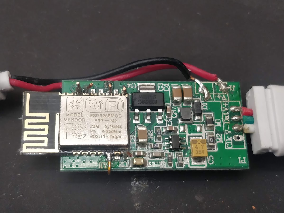
I had bought one of these boards, too.
I soldered the respective wires to the ESP chip, but I could not flash anything to it - not even read the flash contents.
It seems to have the serial wires disconnected (I think you can burn some fuses to protect to read or even change the flash contents).
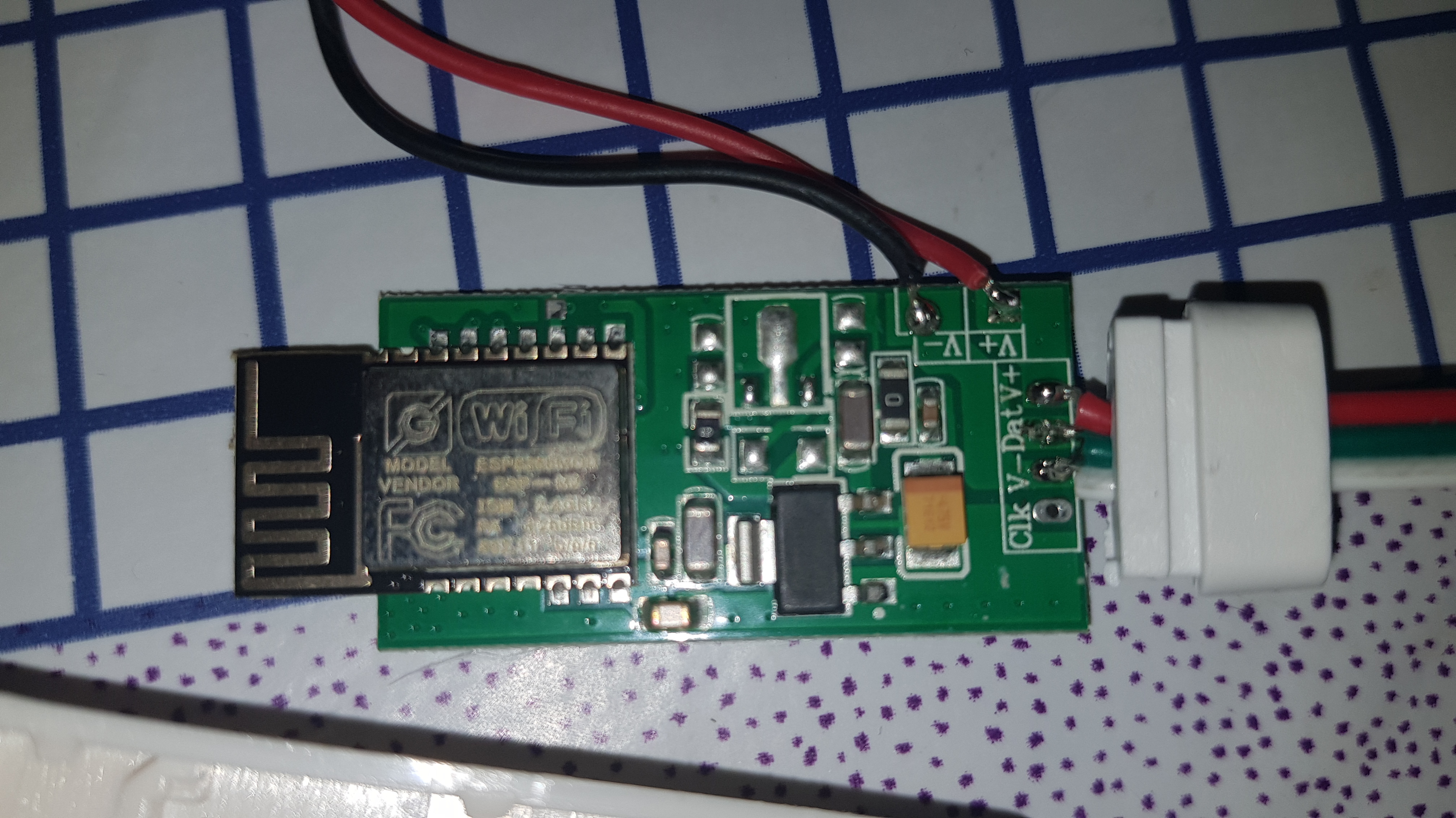
This is the front side:

...and this the back side:

 Def3nder
on 1 Dec 2019
Def3nder
on 1 Dec 2019
Surely we can solder directl on to the main board rather then daughter board to flash it ?
jonny190
on 1 Dec 2019
You can try it on your own - I've flashed a lot of different ESP chips but this one I could not ...
...and I had directly soldered to the main board (of the ESP).
If you are speaking about the ARM chip (and not the ESP) - yes, this one you could propably flash, but that wasn't the question in this thread.
Def3nder
on 2 Dec 2019
Actually, it has already been flashed. Esphome already sees him. It remains to configure the config for the tape, I still do not understand how. Apparently, because of the mcu, the tape cannot be controlled ...


 KeNt606
on 3 Dec 2019
KeNt606
on 3 Dec 2019
@KeNt606 the ARM MCU speaks flux_led binary at 9600 baud to control the strip. You can either bypass it, or wait for support in ESPHome, which I'll probably start work on next week if nobody else is already working on it.
 brandond
on 7 Dec 2019
brandond
on 7 Dec 2019
@brandond This is great news, I look forward to it.
KeNt606
on 7 Dec 2019
Now when I think about this further, it was basically the enclosure I found nice and convenient. I wonder if there's a devboard that could fit in there. Might be the easiest fix as I really don't see the point with the separate ARM chip. Or am I missing something here? :smirk:
ristomatti
on 8 Dec 2019
Or perhaps just destru...desoldering the extra MCU and bypassing it like suggested already...
ristomatti
on 8 Dec 2019
I'm having the same issues as @Def3nder i cant flash either of my 2 :/
jonny190
on 13 Dec 2019
Mine flashed just fine. Hook up probes or solder wires to vcc/gnd/rx/tx/gpio2 as usual. Short EN to ground while holding GPIO2 to ground, then flash as usual.

I do agree with @ristomatti though, the best thing about this is the form factor. I don't need any of the extra stuff and in fact it's a bit of a negative.
brandond
on 13 Dec 2019
Ahhhh haaaa ive got it flashed :) just not getting any patterns off it, i'll troubleshoot and see what i can find
jonny190
on 15 Dec 2019
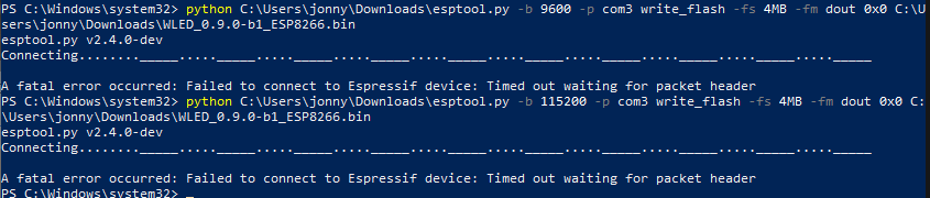
I'm working on the same one right now. In case it helps anyone else, I successfully flashed it this way:
esptool.py --baud 115200 --port /dev/cu.usbserial-1410 write_flash -fs 4MB -fm dout 0x0 ~/Downloads/WLED_0.9.0-b1_ESP8266.bin
The web server is running fine.
Edit: I connected the LED data line to GPIO2, and WLED is working fine!
 tgerla
on 17 Dec 2019
tgerla
on 17 Dec 2019
Thanks a million! Just got a bunch of these in the mail 🤗 Is there a way to get GPIO2 through the 74HC275 without soldering?
 Redferne
on 21 Dec 2019
Redferne
on 21 Dec 2019
@Redferne no, you are tied to the colors and patterns baked into the Arm chip unless you cut some traces and solder a jumper wire.
brandond
on 21 Dec 2019
Good stuff. I modded three of these to have in the 2019 Christmas Tree. To my surprise they sent me 12-24V units while I actually ordered 5V. But it's still working beautifully, I just need to feed the controllers 12V and the WS2813 strip 5V. So 900 LEDs are running synchronised thanks to the wonderful WLED! Thanks a million!

Redferne
on 23 Dec 2019
@Def3nder i have the same problems like you have, i'm not able to flash the esp8285. what have you done? do you think it make sense to order new chips and solder them to the board? or just kick it in the bin?
 Dreamoffice
on 1 Mar 2020
Dreamoffice
on 1 Mar 2020
Hi @Dreamoffice, in the linked ESPurna wiki they describe how to do it - I did it "like all other ESPs on such boards" and (connect RX,TX,3.3,GND, GPIO0) but this did not work.
@brandond mentioned to connect the EN pin to ground, too.
This I did not do - so I think this has been the problem.
After that I did not try further.
To get it running with WLED you would need to solder some wires to use the bus transceiver HC245 like @Redferne showed above.
I will give it a try - will need some more spare time ... 😃
Def3nder
on 2 Mar 2020
@brandond do i need to connect Gpio0 gpio2 and EN to ground during flashing?
Dreamoffice
on 2 Mar 2020
i also had trouble flashing but in the datasheet it mentioned the baud rate sometimes can be 74880 baud, so i followed http://cholla.mmto.org/esp8266/weird_baud/ and that fixed my issues
 Scriptkiddi
on 3 Mar 2020
Scriptkiddi
on 3 Mar 2020
@Scriptkiddi how did you manage bringing the esp to flash mode?
Dreamoffice
on 6 Mar 2020
pulling the gpio0 to ground
Scriptkiddi
on 6 Mar 2020
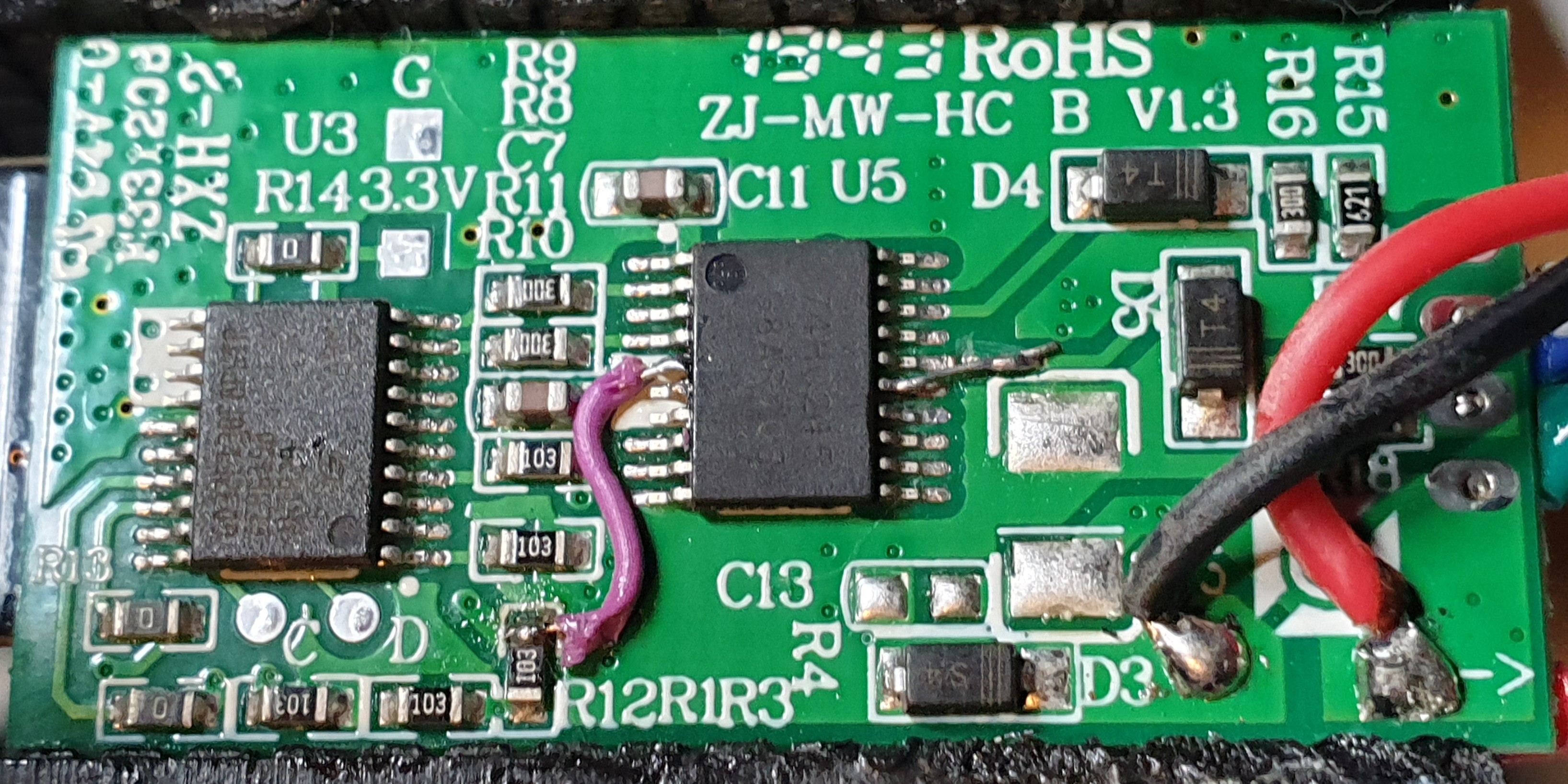
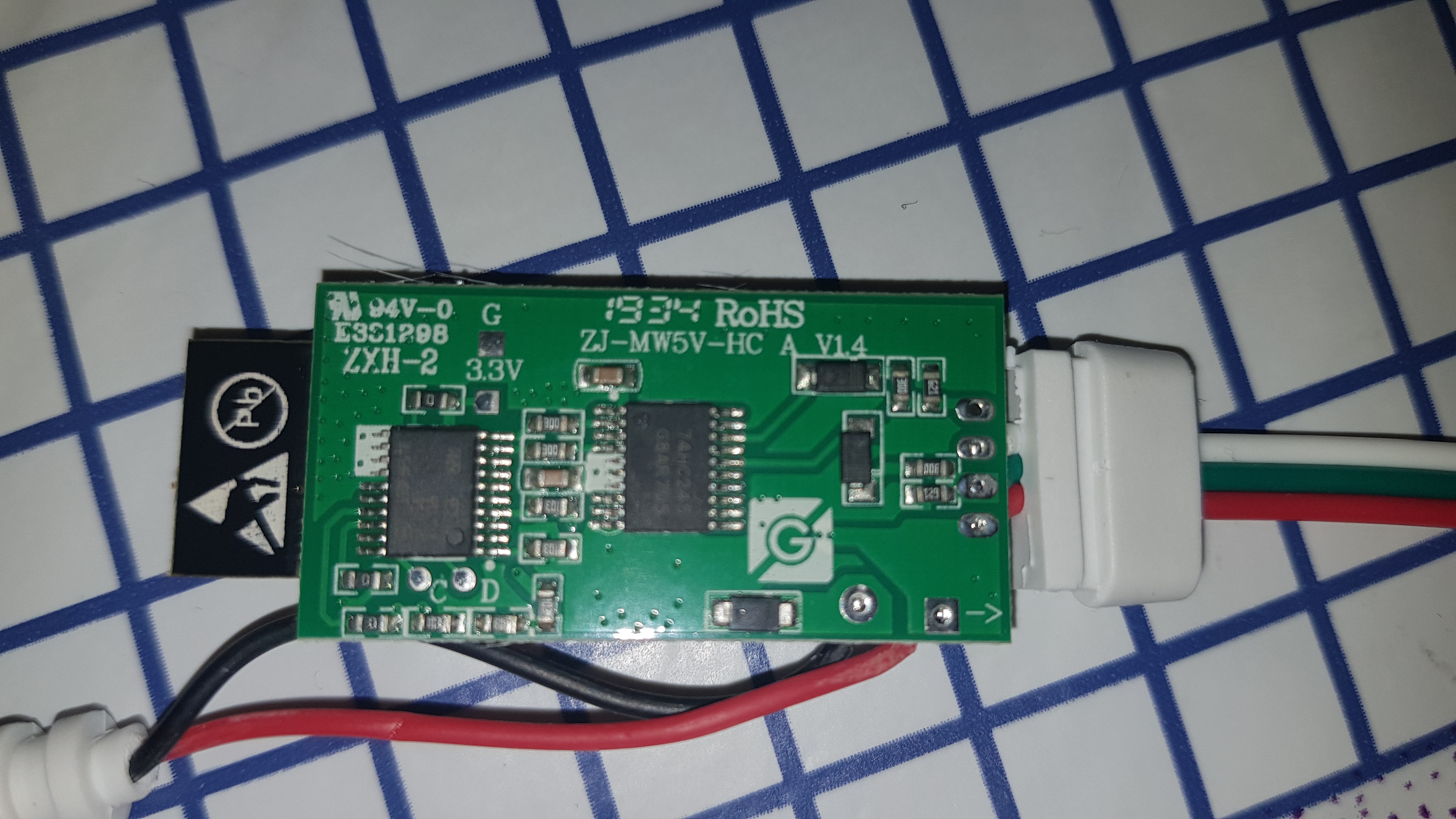
You can mod this with one cut and one wire.
- Cut the two traces coming from the top right of the ARM chip to R10 and R11, just below the R10 silkscreen; this disconnects the chip from the level shifter inputs.
- Run a wire around the edge of the board from GPIO13 to left side of the R10 resistor. This connects GPIO13 to the level shifter input, which will convert the ESP8266 output from 3.3v to 5v.
- You can optionally also remove R12 and R13 from the bottom left of the board; this disconnects the ESP8266 UART from the ARM chip so that you're free to use it for other things.
Pictures:

I will also note that the clock line is connected all the way through from the ARM chip and level shifter to the pad on the edge of the board; these could easily be used for clocked (SPI) LEDs by wiring another GPIO into R11 and soldering on a 4-wire connector.
brandond
on 11 Mar 2020
how can i check if the esp is in flash mode?
Dreamoffice
on 12 Mar 2020
@brandond thanks a lot I will give that a try
@Dreamoffice if you get something like this rst cause:4, boot mode:(1,6) from the uart read out the important part is the 1 which implies you can flash it
Scriptkiddi
on 12 Mar 2020
@brandond could you please add some pictures?
Dreamoffice
on 13 Mar 2020
edited @Dreamoffice
brandond
on 13 Mar 2020
@Def3nder it would be very interesting for me if you will find a way to flash it. i tried a lot but no success.
Dreamoffice
on 15 Mar 2020
I finally managed to flash mine.
I flashed the 1MB flash version as the ESP8285 is only supposed to have 1MB flash, according to specs I found online.
Did you guys have any luck flashing the full 4MB version?
 MrGuy
on 15 Mar 2020
MrGuy
on 15 Mar 2020
You can mod this with one cut and one wire.
* Cut the two traces coming from the top right of the ARM chip to R10 and R11, just below the R10 silkscreen; this disconnects the chip from the level shifter inputs.

* Run a wire around the edge of the board from GPIO13 to left side of the R10 resistor. This connects GPIO13 to the level shifter input, which will convert the ESP8266 output from 3.3v to 5v.

* You can optionally also remove R12 and R13 from the bottom left of the board; this disconnects the ESP8266 UART from the ARM chip so that you're free to use it for other things.
Thanks of guide, I finally got my Magic Home SPI and WS2811-strip working with these modifications. As small modification I had to change LEDPIN into 15 at NpbWrapper.h (since on picture it looks like it was connected into second pin).
 anounyym1
on 25 Mar 2020
anounyym1
on 25 Mar 2020
Thanks for the clear guide @brandond, however i'm having some trouble flashing the esp. I want to flash esphome to it so I can use it with homeassitant.
I tried flashing it with my USB to TTL serial cable(CP2102) but it is unclear to me what pins I should connect to where.
Hope someone can help.
 coen800
on 24 Apr 2020
coen800
on 24 Apr 2020
@coen800 If you google 'esp-m2 pinout' you should get some pictures that will help you figure out where the vcc, ground, tx, rx, and gpio2 pins are.
brandond
on 24 Apr 2020
Thanks @brandond, managed to flash the esp. Now i'm having isuess with the esphome configuration. Sorry for the questions, first time fiddling with ws2811 LEDs on esphome.
If I understand correctly this would be a valid config for the same setup as your pictures;
light:
  - platform: rgb
    name: "ledstrip_new"
    red: output_component1
    green: output_component2
    blue: output_component3
output:
  - platform: esp8266_pwm
    id: output_component1
    pin: GPIO13
  - platform: esp8266_pwm
    id: output_component2
    pin: GPIO13
  - platform: esp8266_pwm
    id: output_component3
    pin: GPIO13
When I turn the led on it does nothing, when I select a color in the color wheel it goes static white no matter what color I chose. Does anybody have a example config for ws2811 LEDs?
coen800
on 24 Apr 2020
This is a clockless single-channel driver, not clock+data or multi-channel PWM (which is what you've attempted to set up). If it was multi-channel PWM, you'd need a separate GPIO pin for each color.
What you want is https://next.esphome.io/components/light/fastled.html#clockless or https://next.esphome.io/components/light/neopixelbus.html - fastled would be my recommendation.
brandond
on 24 Apr 2020
Can somebody help me how to flash this? I've grounded down the gpio 0 before I powered up (from the original power cord not from the serial reader. Then I connected the Tx/Rx ports to the serial reader. I tried to flash with tasmotiser, esphome flasher and nodeMCU. All have the same issue, packet header not received. The ESP's own wifi network is not visible so I guessing it's in flashing mode. When I see transfer on Tx, I see also transfer on the Rx. (Led indicator blinking on the serial board.)
 golddragon007
on 6 Jun 2020
golddragon007
on 6 Jun 2020
@golddragon007 please connect the grounds of the ESP and flasher, otherwise you will not get a reliable transfer. Hooking up the reset pin could also help, although I'm not sure if that is technically required because I only use boards with built-in USB 😅
Aircoookie
on 6 Jun 2020
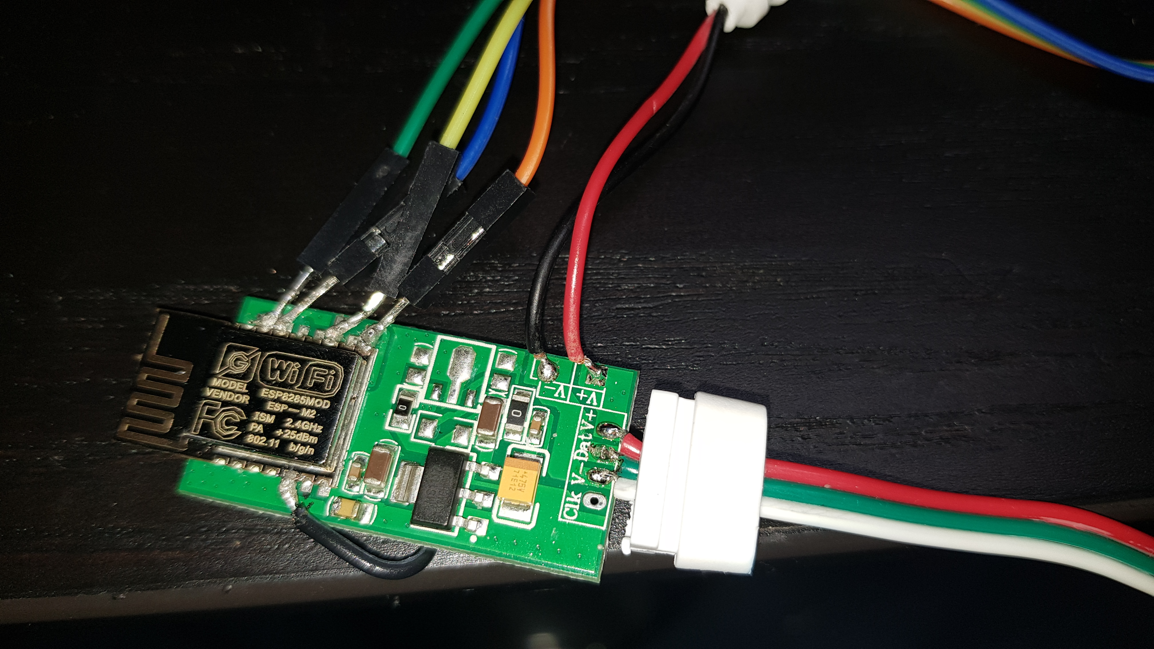
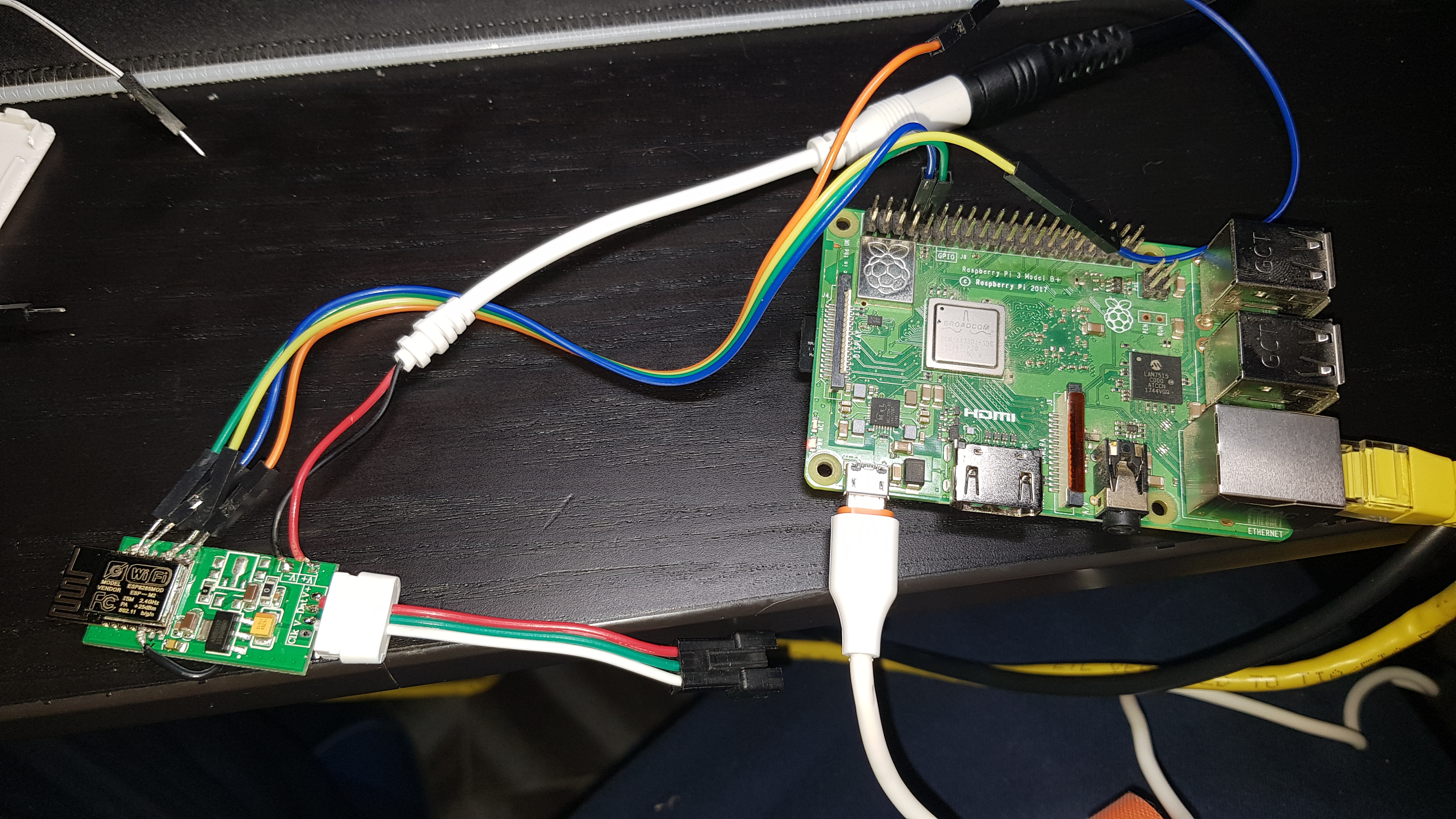
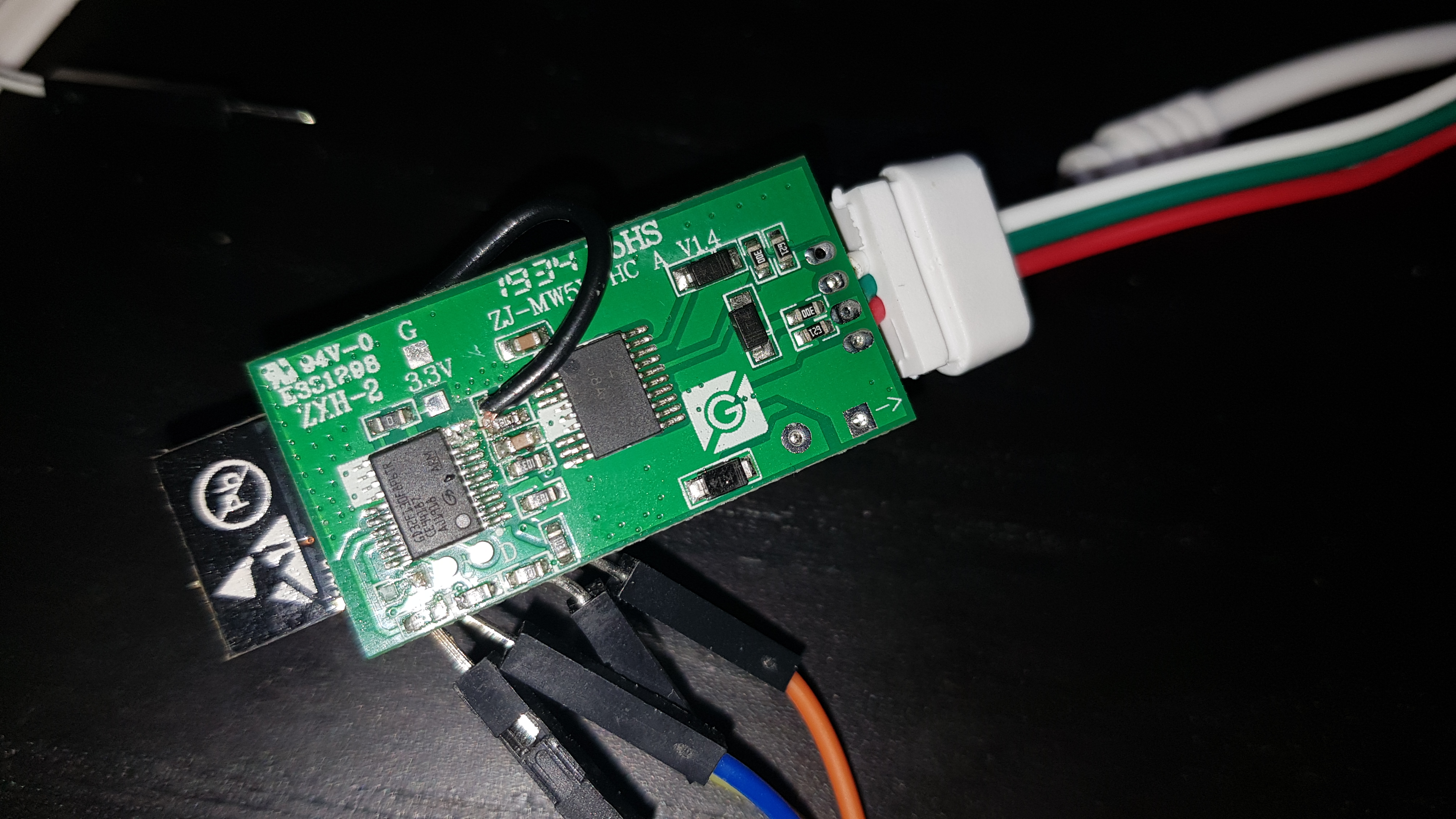
I'm still unable to flash these:
With the following pin connections, any ideas? (ignore the 3.3v line it snapped off XD)
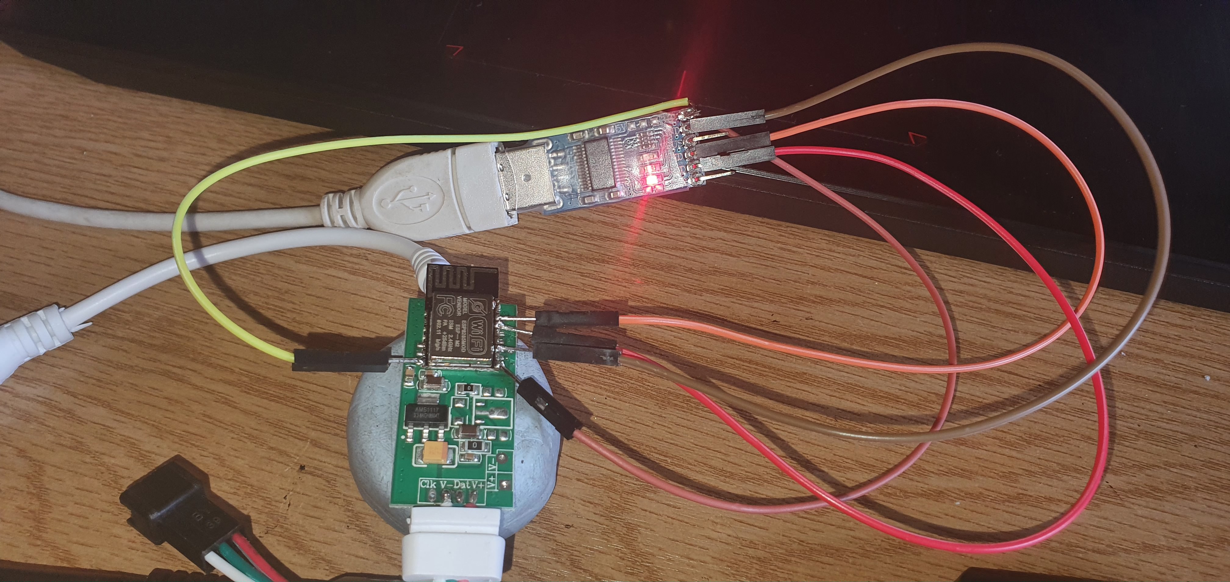
jonny190
on 19 Jun 2020
@jonny190 in my experience those adapters don't provide enough voltage. I've also found that it doesn't work well if you power them up with rx and tx connected. Connect ground, gpio, and power, then tx and rx. You may need to momentarily ground the en pin as well to reset it.
brandond
on 19 Jun 2020
@jonny190 in my experience those adapters don't provide enough voltage. I've also found that it doesn't work well if you power them up with rx and tx connected. Connect ground, gpio, and power, then tx and rx. You may need to momentarily ground the en pin as well to reset it.
Thanks for the heads up,
Just tired powering it from a 5V usb as designed with gpio ground connected then added TX and RX but still no luck
Ive also tried ground and 3.3v from the usb then added TX and RX still nothing
If i power the unit up normally it shows in the MagicHome App still (i havent connected it to WiFi or anything) so the units still alive
jonny190
on 20 Jun 2020
So finally I've made it. I've needed to remove two resistors from the other side of the board, to open the connection between the ESP and MCU. Then, because I was soo lazy to solder pins to esp, I've made fast from five-pin connector a holder which I was able to bend to touch the correct pins on the esp. I've put the ground and the reset pin on top of the esp and I've held it there till the end of the flashing, The other was held next to the esp around 45 degrees to have good contact with the pins. I did this successfully with all my 7 boards, now I will need to figure it out which pin do I need to solder to which other pad on the board to be able to communicate with the LEDs.
golddragon007
on 2 Jul 2020
You can mod this with one cut and one wire.
- Cut the two traces coming from the top right of the ARM chip to R10 and R11, just below the R10 silkscreen; this disconnects the chip from the level shifter inputs.
- Run a wire around the edge of the board from GPIO13 to left side of the R10 resistor. This connects GPIO13 to the level shifter input, which will convert the ESP8266 output from 3.3v to 5v.
- You can optionally also remove R12 and R13 from the bottom left of the board; this disconnects the ESP8266 UART from the ARM chip so that you're free to use it for other things.
Pictures:
I will also note that the clock line is connected all the way through from the ARM chip and level shifter to the pad on the edge of the board; these could easily be used for clocked (SPI) LEDs by wiring another GPIO into R11 and soldering on a 4-wire connector.
I followed exactly this and I flashed a custom binary where I set the LEDPIN to GPIO 13, but I'm running into this flickering issue when I connect my esp to a led strip. What is this due to in your opinion ?
Also the esp doesn't enable AP mode after I power it up so I can't access it in the first place.
 taha-yassine
on 13 Aug 2020
taha-yassine
on 13 Aug 2020
Hi guys,
I brought this 2 days ago from eBay and I was wondering if is it possible to flash mine as well. The controller has a different revision then the other posted by @brandond
It have some differences like C12 and C13 missing.
Before messing up do you believe I can flash it?
Thanks
 Novocaine85
on 15 Oct 2020
Novocaine85
on 15 Oct 2020
If the ESP chip is the same you will be able to reprogram it, but why missing 4 components and 2 by 2 pads from it at least... That's the question for me...
golddragon007
on 15 Oct 2020
@Novocaine85 I think it should be flashable.
@golddragon007 Could be 5V version so it needs only AMS1117 to stepdown to 3.3V for ESP.
 Shamshala
on 15 Oct 2020
Shamshala
on 15 Oct 2020
I have soldered the wires. Having a raspberry pi 3, do you know where do i need to put the pins? rx to tx, tx to rx ground to ground and i'm missing one 😅
Novocaine85
on 15 Oct 2020
I'm trying but i get:
A fatal error occurred: Failed to connect to Espressif device: Invalid head of packet (0xE0)
When i try to put EN to ground i get:
A fatal error occurred: Failed to connect to Espressif device: Timed out waiting for packet header
So i guess my pi and the esp m2 are communicating some how but they don't "speak" each other.
Why GPIO13 must be attached to R10 resistor in order to get 3,3V?
Novocaine85
on 16 Oct 2020
No, it's for protection normally, if I remember well. When you start the device it can have peaks that can damage the chip, to prevent this a resistor is added, where the 'extra' power/current will drop, instead of inside the chip.
You get that error because probably you didn't cut the wire between the esp and the microprocessor, pls see the picture a few posts up. Nope, this is needed for the data, for flashing you need to remove the two resistors.
golddragon007
on 17 Oct 2020
Definitely I did.
Novocaine85
on 17 Oct 2020
Hi friends, i modified and successfully flashed my magic home controller, and it work good, but i have small problem: when i set an effect for ex. rainbow, every one-one and half hour it suddenly change to the yellow color, color like when you start first time, bud it doesn't reset, it's only color change. Any idea what can cause this?! I have flashed 0.10.1 version.Thanks for help.
EDIT: i checked already the info window in the app, and i see that every time, that the problem occurs, the uptime timer start from 0,so i think this is an completely system restart, not only "color change", i have 5V/8A power supply, so i don't think, that this is the problem.
 kuno23
on 20 Oct 2020
kuno23
on 20 Oct 2020
@kuno23, try monitoring free memory and uptime until it resets to get any clues:
curl http://IP/json/si |jq '.info.freeheap, .info.uptime'
maybe there's a pattern.
 pille
on 20 Oct 2020
pille
on 20 Oct 2020
@pille thank for you reply.. I monitored the device and values until it restart are memory between 17560 - 18300 and time is of course every time different, sometimes half hour, sometimes one and half hour, sometimes hour.. But i think if i set only one solid color, for ex. now i have blue and it work almost 4hour without any problem.
kuno23
on 21 Oct 2020
@kuno23 so this looks like a power/load problem, as solid blue consumes less power than green+red (yellow).
as you mentioned, your PSU looks ok, though.
how many LEDs are you driving?
you may experiment with less LEDs, or limit their brightness in the settings.
does it reset faster, when using solid white (max power consumption)?
is there any difference to having it flash black/white fast?
does it reset at all, when all LEDs are black?
pille
on 21 Oct 2020
@Novocaine85 As I see you've jumped into the same rabbit hole like me. You need to connect the ground to your flasher's ground. (So esp ground and flash pin needs to be connected to pi's ground.) That hook is not enough for whatever reason. Also, check the signal voltage on the tx/rx pins. I think it can't be higher than the power supply voltage (3.3v) otherwise you can/will damage the chip obviously.
Also, I've noticed that you soldered the data pin to GPIO 13, by default the data pin is GPIO 2 (see: wled00/NpbWrapper.h LEDPIN definition), which is located between the GND and FLASH pins. IF you want to use the GPIO 13 you need to compile your own bin or you need to resolder that wire.
golddragon007
on 21 Oct 2020
@Novocaine85 As I see you've jumped into the same rabbit hole like me. You need to connect the ground to your flasher's ground. (So esp ground and flash pin needs to be connected to pi's ground.) That hook is not enough for whatever reason. Also, check the signal voltage on the tx/rx pins. I think it can't be higher than the power supply voltage (3.3v) otherwise you can/will damage the chip obviously.
Also, I've noticed that you soldered the data pin to GPIO 13, by default the data pin is GPIO 2 (see: wled00/NpbWrapper.h LEDPIN definition), which is located between the GND and FLASH pins. IF you want to use the GPIO 13 you need to compile your own bin or you need to resolder that wire.
Thank for your advice. I've ordered a CH340 usb key since i'm unsure that the raspbi is able to flash those kind of things. I'll try again when the item will arrive.
Novocaine85
on 21 Oct 2020
@Novocaine85 I've checked it for you, according to this: https://www.raspberrypi.org/documentation/configuration/uart.md all of the tx/rx are 3.3V. So you are safe. The only thing that you need to do then to connect the esp ground and flash to the raspberry pi's gnd pin. And use the correct GPIO ports.
golddragon007
on 21 Oct 2020
@pille hi, i driving 120leds, i replaced the psu for new one, have limited the current to 850mA as default, and brightness too, to 128. Flashing black/white fast cause device disconnection after 30s and after 2-3min device reset.. I will monitor it with white color how long it will work..
kuno23
on 21 Oct 2020
60leds cause the same problem, device disconnection from wifi, then restart.. Now testing 30leds,and for now working fine, more like 3-4hours..but 30leds are very few for my purpose.. I will try to connect then power from psu directly to the strip, and from the board will use only the data pin.. Maybe there is some problem with the power board, high current that the IC on the board cannot handle and cause the restart..
kuno23
on 22 Oct 2020
after some testing I believe that my chip is dead. Notice that is unable to connect to wifi or show the wireless network in order to get it configured.
I need to find out if there is some diagnostic tool somewhere, but i'm pretty sure that is dead.
Novocaine85
on 23 Oct 2020
How did you reach that point? Were you able to flash it? Maybe you need to reflash it again.
golddragon007
on 23 Oct 2020
How did you reach that point? Were you able to flash it? Maybe you need to reflash it again.
Unable to flash it and never be able to get it in flash mode. I tried all the advise you all gave me but I'm unable to flash it nor make it work. I don't know if I'm doing something wrong (probably). I tried the ch340 as well but no clue.
Novocaine85
on 23 Oct 2020
If it's in flash mode, the wifi doesn't show up. Under the boot pin, there's a pad, if that's the ground and you soldered together with the boot pin, it will never show up any wifi network. Check this before you write it down.
golddragon007
on 23 Oct 2020
@golddragon007 after re-resoldering the wires, I was able to flash it 🎉🎉🎉
Thank you again for your suggestions. Probably I'm not good at soldering wires and stuff. 😅
I'll compile the firmware in order to use GPIO 13 as you mention here.
Changing the GPIO definitions in that file and compiling is enough?
Novocaine85
on 24 Oct 2020
@Novocaine85 That's why I just created a mock that I've held it to the pins when I flashed it... I didn't want to solder two pins together and then I've needed to unsolder them. So nooo way...
According to this: https://github.com/Aircoookie/WLED/issues/398#issuecomment-604081260 yes. Just if you with this, you need to remember that you can't update with the released firmware, you will need always to translate your firmware.
golddragon007
on 24 Oct 2020
hi can i flash the same model of @Novocaine85 with arduino uno using arduino ide? and the schematic? in internet i see tutorial with arduino but only 8 wire esp module...is possible with 4 pin serial ? thank you
 drakengard780
on 29 Oct 2020
drakengard780
on 29 Oct 2020
@golddragon007 after re-resoldering the wires, I was able to flash it 🎉🎉🎉
Thank you again for your suggestions. Probably I'm not good at soldering wires and stuff. 😅
I'll compile the firmware in order to use GPIO 13 as you mention here.
Changing the GPIO definitions in that file and compiling is enough?
Hi @Novocaine85 did you manage to get your controller working correctly with your lights? I was able to recompile using GPIO 13 and flash successfully but my lights flicker a lot and I'm getting lots of syntax and file systems errors on the config page. Did you experience the same issues?
 adamwhiteland
on 7 Dec 2020
adamwhiteland
on 7 Dec 2020
@golddragon007 after re-resoldering the wires, I was able to flash it 🎉🎉🎉
Thank you again for your suggestions. Probably I'm not good at soldering wires and stuff. 😅
I'll compile the firmware in order to use GPIO 13 as you mention here.
Changing the GPIO definitions in that file and compiling is enough?Hi @Novocaine85 did you manage to get your controller working correctly with your lights? I was able to recompile using GPIO 13 and flash successfully but my lights flicker a lot and I'm getting lots of syntax and file systems errors on the config page. Did you experience the same issues?
At the end I gave up and used an esp8266 for the purpose. I had the same issues as well. Flickering and errors.
Novocaine85
on 8 Dec 2020
Hi @Novocaine85 did you manage to get your controller working correctly with your lights? I was able to recompile using GPIO 13 and flash successfully but my lights flicker a lot and I'm getting lots of syntax and file systems errors on the config page. Did you experience the same issues?
At the end I gave up and used an esp8266 for the purpose. I had the same issues as well. Flickering and errors.
Myself I had to erase my esp8266 before flashing with "esptool.py erase_flash"-command, or otherwise it would show these errors.
For building I currently use following on platformio.ini:
[env:esp8266]
board = esp01_1m
platform = ${common.platform_wled_default}
board_build.ldscript = ${common.ldscript_1m128k}
build_flags = ${common.build_flags_esp8266} -D WLED_DISABLE_OTA -D WLED_DISABLE_INFRARED
Hello, sorry for this question if its not the right place to ask it, but I need to control just 4 analog RGB leds. I want to use WLED. Is it possible to use the magichome controller to do it?
I mean, if I am able to flash the device, it should work right?
Any tip on controlling analog RGB?
Thank you
 t0mb3r
on 14 Dec 2020
t0mb3r
on 14 Dec 2020
Related issues
 klrock
·
45Comments
klrock
·
45Comments
 ozzi91
·
61Comments
ozzi91
·
61Comments
 dpackham
·
34Comments
dpackham
·
34Comments
 JanBosNL
·
28Comments
JanBosNL
·
28Comments
 toyotaspeed90
·
31Comments
toyotaspeed90
·
31Comments
Most helpful comment
@KeNt606 the ARM MCU speaks flux_led binary at 9600 baud to control the strip. You can either bypass it, or wait for support in ESPHome, which I'll probably start work on next week if nobody else is already working on it.