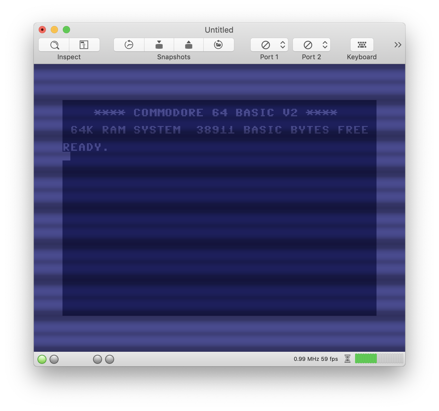
Hi! Excellent emulator, it has the potentional to be better than VICE in ease of use, and it feels much more Mac-like in design.
I have a couple of minor issues with the graphics emulation though. None of the palettes seem to be 100% true to the C64 colors. The brightest grey colour should be brighter in tone than the pink or bright red. It would be great if you could update the VICE colour palette to be closer to what is default in VICE, since that palette seems pretty accurate in my eyes.
Also, the CRT filter is a great starting point, but would look even better with some bloom and blurring applied. Check out the comparison on my site: http://www.superrune.com/tools/supercrt.php
Cheers!
 superrune
All 119 comments
Hi!
You are right this is an excellent emulator for OSX and the Super CRT filter would be a great option for us...
 Alessandro1970
on 28 Dec 2017
Alessandro1970
on 28 Dec 2017
Super CRT looks super cool, thank you very much for pointing to your site! I hope to get your shader integrated in VirtualC64 soon. Unfortunately, I am not a shader expert and need to dig deeper into Metal first. As far as I understand, it's necessary to port the .cg shader stuff to Metal's own shading language.
 dirkwhoffmann
on 31 Dec 2017
dirkwhoffmann
on 31 Dec 2017
RGB values of all VICE palette colors have been updated. The VICE palette is now the factory default setting.
dirkwhoffmann
on 7 Jan 2018
I have checked in a couple of changes to the VirtualC64's Metal implementation. Texture post-processing is now done in 2 stages. In stage 1, the original C64 texture ist upscaled (x2). Pixels can either be converted to 4x4 quads ("bypass" upscaler) or converted via a pixel upscaling algorithm. As a proof of concept shader, I have implemented EPX (Eric's Pixel Expansion). In the second stage, the texture is filtered. This is where Super CRT would come into play.
Do you know by chance on what texture size Super CRT is working in OpenEmu. In Virtual C64, it would run on a double resolution texture as described above. Is this similar to what OpenEmu is doing?
In addition, I still have some problems understanding supercrt_crt-geom.cg. By looking at the code, I can see that value "mod_factor" is computed in the vertex shader which is later used by the fragment shader. However, mod_factor seems to be a pixel dependent value. But isn't the vertex shader called only for the edges of each triangle instead of each pixel?
dirkwhoffmann
on 12 Jan 2018
Hi Dirk - fantastic that you're looking into this! Checking the palette now! Actually, my programming experience is very limited, and the Super CRT shader is based on a couple of shaders I found on the libretro/common-shaders distro. I probably won't be able to help you with how it works, but I can tell you the look I was going for:
- I found a shader that did scanlines on every pixel line, halving the intensity on half of the line
- I then blurred out the entire image and added that very subtly on top for a glow effect
- Finally, a very very slight curvature effect was added, with rounded corners.
So nothing fancy at all. I found a site that explains how the CRT behaves on a PAL screen, maybe that could be interesting for you: http://hitmen.c02.at/temp/palstuff/
The final picture in the article feels like the C64 looked on my old Commodore monitor!
superrune
on 15 Jan 2018
I do not think there is a need to integrate a new CRT mode in VirtualC64; if anything, a different system to smooth the graphics without completely distorting the image.
Do you think it like me?
 puleyo
on 5 Jul 2018
puleyo
on 5 Jul 2018
I think the supercrt shader really looks cool. However, it's not that easy to integrate because the code has to be ported to Metal and I'm not a Metal expert (the supercrt shader code itself isn't that easy to understand, too).
Regarding another upscaler, Power64 had one which seems to produce nice results in text mode ("Full Antialiasing"). It would be cool to have this upscaler as an option, in addition to the two already implemented upscalers.
dirkwhoffmann
on 5 Jul 2018
Ive never been a fan of smart scaling filters like the “full antialiasing” or “simple smoothing”
Personally, I think something based on “black interlace” would be he best. But you would need to do some tweaking to get something that perceptually is closer to a real crt:
- make the black lines not pure black, but instead 30 to 50 percent intensity of the regular lines
- blur the result and add it back on top of the unblurred image. Adjust the additive amount so that the perceived brightness is equal to a non-filtered image.
I’d be happy to do a quick mock-up when I’m in front of my computer the next time!
Also, check out the Vice c64 emulator for Raspberry Pi, it has a very simple crt filter that creates a lovely look with a bare minimum (scanlines + blur).
superrune
on 5 Jul 2018
Hi,
of course the SuperCRT probably offers the best result, but even the Full Antialiasing especially with some games makes it very well.
I do not own the Raspberry, could you show us a picture of this CRT + "tiny - blur" mode?
Bye
Alessandro1970
on 6 Jul 2018
Using an upscaler and an effect filter (such as CRT) is not exclusive. In the current pipeline, the texture is first upscaled and then passed through the effect filter. Hence, "Full Antialiasing" and "SuperCRT" (once implemented) could be combined.
dirkwhoffmann
on 6 Jul 2018
Personally, I don't like blur filters or CRT filters. I love scanlines though! Created a pull request for a 75% height 50% intensity filter.
50% height and 75% intensity looks good too, but my preference was the former.
Would be nice to have a knob for scanline intensity, blur, etc.
 jimrogerz
on 26 Oct 2018
jimrogerz
on 26 Oct 2018
Good result, excellent work.
At this point I think this issue can be closed, the VirtualC64 has enough filters and options.
puleyo
on 26 Oct 2018
Jim, thank you very much for implementing the scanline filter. I already merged the code.
I took your work as an opportunity to look into the Vice c64 emulator for Raspberry Pi this morning (the crt filter which superrune mentioned in one of his posts above). I found the shader here in glsl format:
https://github.com/libretro/glsl-shaders/blob/master/crt/shaders/crt-pi.glsl
I'll try to port this shader to Metal. It looks promising, because the shader is pretty short and combines the typical CRT effects (Scanlines, Curvature, Blooming, and Masking) in one single shader.
Depending on the outcome, we can decide if an even more complicated CRT filter should be tried (such as Super CRT)
dirkwhoffmann
on 26 Oct 2018
Awesome to see you still working on this. I know that much of this is down to personal preference, some like the filters and some don't - but there is no escaping the fact that a true CRT emulation/simulation needs scanlines (or dot mask) and a subtle glow/bloom to look real.
Fantastic if you could convert the crt-pi shader to VirtualC64. Its a very very nice shader, I would be happy using that!
Some screenshots of it here if anyone is curious:
https://github.com/RetroPie/RetroPie-Setup/wiki/Shaders-and-Smoothing#shaders
Cheers!
superrune
on 26 Oct 2018
I am at a point where I have to decide between two implementation choices:
a) Implement the CRT filter as a compute shader that transforms the (upscaled) texture to another texture of the same size. This texture is then being used for drawing the quad inside the standard fragment shader. Currently, all filters work that way, including Jim's new scanline filter.
To summarize: We have three pipeline stages right now:
- First compute kernel (Upscaler)
- Second compute kernel (Filter)
- Customized vertex shader and standard fragment shader for transforming and coloring the quad, respectively.
b) Integrate the CRT filter inside the fragment shader. Then, the pipeline would reduce to:
- First compute kernel (Upscaler)
- Customized vertex shader and customized fragment shader for transforming and coloring the quad. The fragment shader will apply the CRT effect.
I think we have to alter the current design and go for option b), because it's the only chance to cope with the moiré effect in a decent way. E.g., the pi-crt shader incorporates MULTISAMPLE as an option to reduce the moiré effects, and this kind of multisampling would not work if the scanlines are part of the texture. As a side effect of b), we would reduce the number of pipeline stages from 3 to 2.
Another (maybe unimportant) consequence of the design decision is the following: In option a), the scanlines rotate with the quad, because they are part of the texture. In option b), the scanlines overlay everything that is drawn behind and therefore don't rotate with the quad.
dirkwhoffmann
on 26 Oct 2018
From crt-pi.glsl:
"By default the shader uses linear blending horizontally. If you find this too blury, enable SHARPER."
Here is the "SHARPER" code:
    vec2 texcoordInPixels = texcoord * TextureSize;
#if defined(SHARPER)
    vec2 tempCoord = floor(texcoordInPixels) + 0.5;
    vec2 coord = tempCoord / TextureSize;
    vec2 deltas = texcoordInPixels - tempCoord;
    float scanLineWeight = CalcScanLine(deltas.y);
    vec2 signs = sign(deltas);
    deltas.x *= 2.0;
    deltas = deltas * deltas;
    deltas.y = deltas.y * deltas.y;
    deltas.x *= 0.5;
    deltas.y *= 8.0;
    deltas /= TextureSize;
    deltas *= signs;
    vec2 tc = coord + deltas;
#else
    ...
#endif

vec3 colour = texture2D(Texture, tc).rgb;
Anybody an idea what this code is actually doing?
dirkwhoffmann
on 26 Oct 2018
Also worth reading: A real bloom effect in Metal:
https://weblog.jamisbuck.org/2016/2/27/bloom-effect-in-metal.html
dirkwhoffmann
on 26 Oct 2018
Using the fragment shader, the Moiré patterns get worse 🤔. Don't know, maybe I implemented multisampling wrong.
dirkwhoffmann
on 27 Oct 2018
Just thinking out loud:
Based on my previous experiments, I think it is more promising to emulate the scanlines inside the texture (as Jim did). However, if we simply wipe out two of the four lines representing a pixel row, we cancel half of the information coming from the upscaler. We might be better off doing the following:
Let the upscaler make 4 rows out of 1 (as it is right now).
Let the CRT filter add an additional 4 rows:
Line 1: Scanline: Black
Line 2: Scanline: Reduced color from row 3 (bloom effect)
Line 3: Row 1 from upscaler
Line 4. Row 2 from upscaler
Line 5: Row 3 from upscaler
Line 6: Row 4 from upscaler
Line 7: Scanline: Reduced color from row 6 (bloom effect)
Line 8: Scanline: Black
The result would be a texture of size 2048 x 4096. This shouldn't be a problem though, because all Metal enabled Macs can handle textures of that size (at least I think so). Right now, the filter stage outputs a texture of size 2048 x 2048.
Bumping up the texture might have the nice side effect that it allows to emulate scanline blooming in a more realistic way.
dirkwhoffmann
on 27 Oct 2018
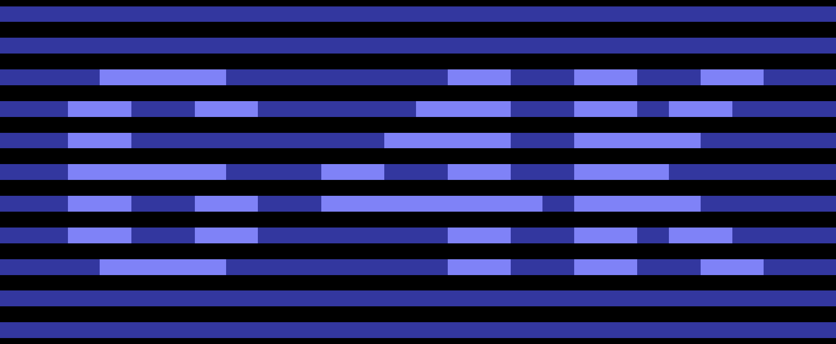
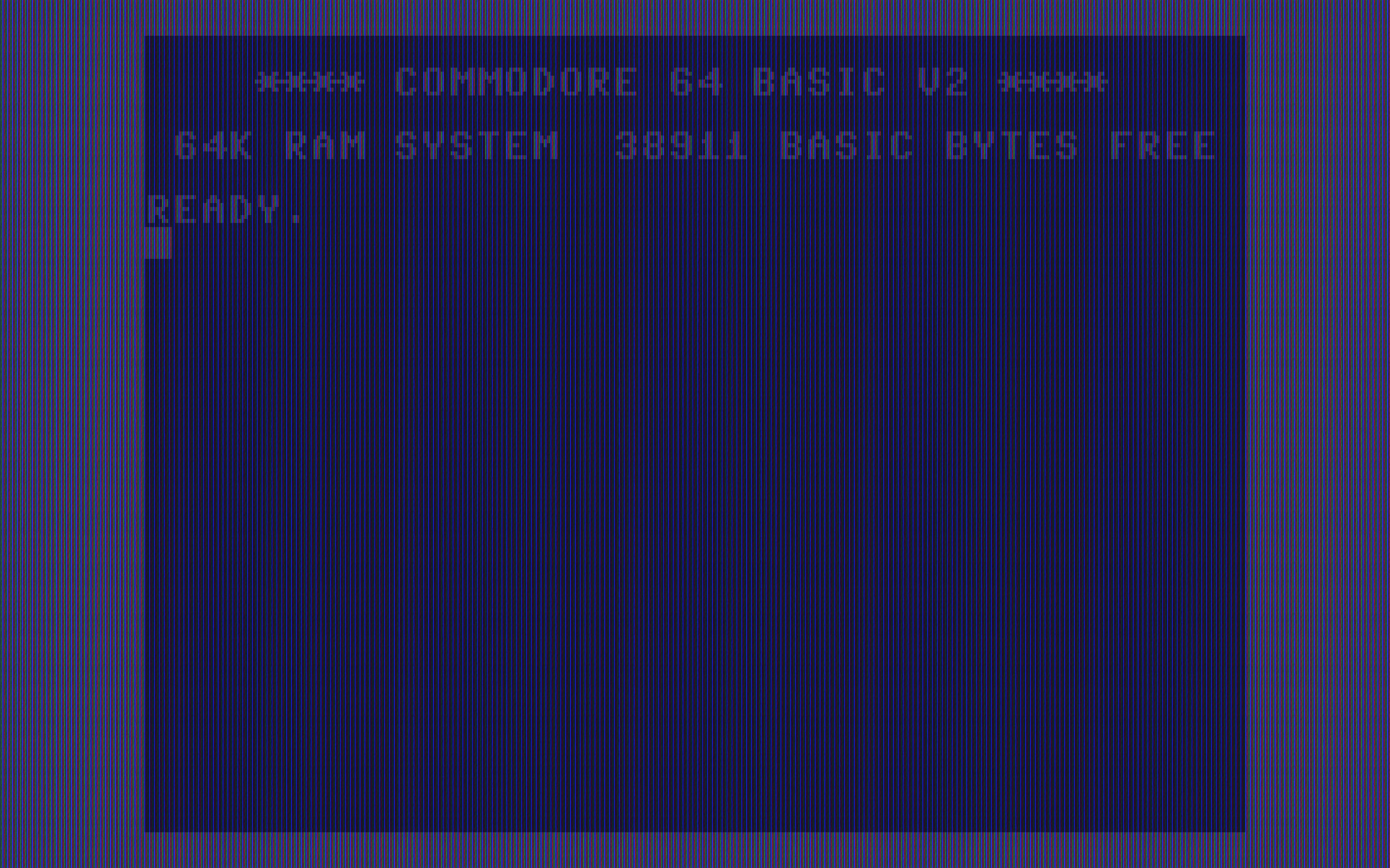
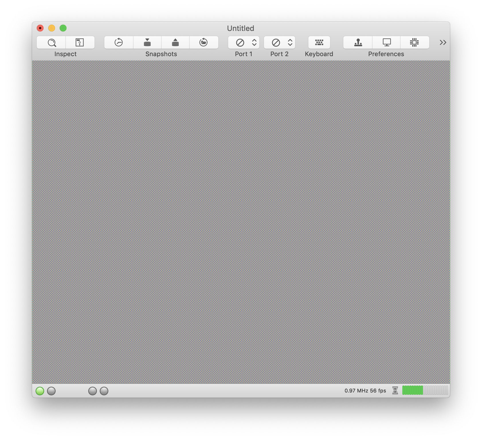
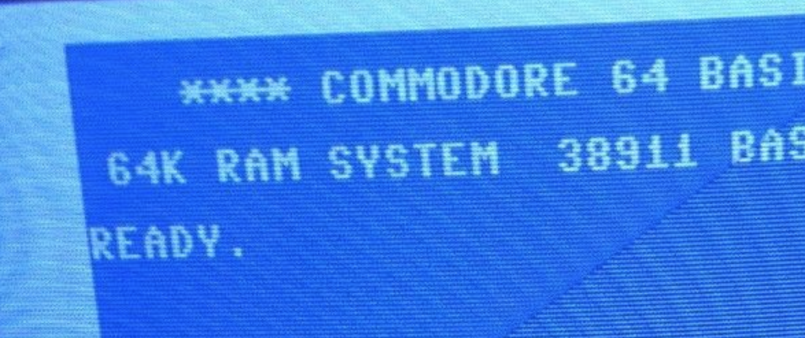
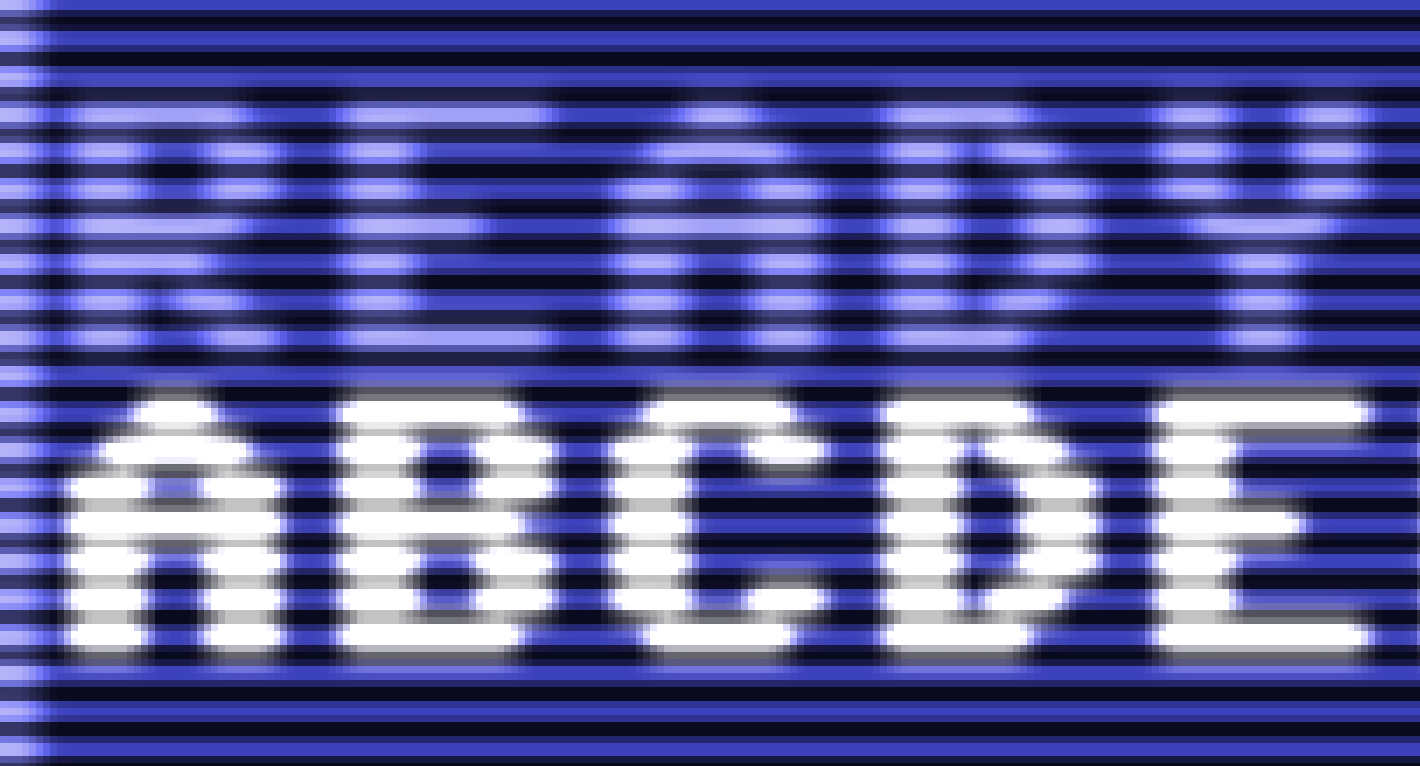
Just an intermediate result: A final output texture of size 2048 x 4096 with 4x upscaling and scanlines:
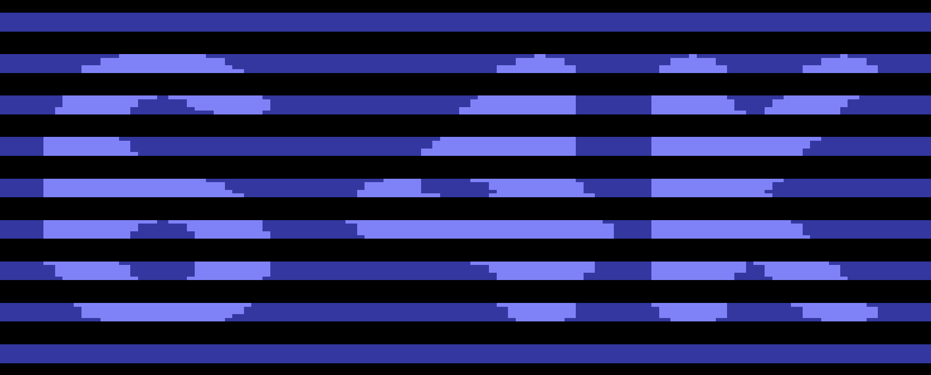
Please note that the output is taken by a screenshot and does not reflect the internal texture to 100%. I took a screenshot, because I don't know how to get the texture out the GPU into a TIF file.
Next step will be to add blooming.
Does anybody know the physical details?
Do R, G, and B bloom with the same intensity?
How does luminance reduce with the distance to the raster beam? Inverse square law?
dirkwhoffmann
on 27 Oct 2018
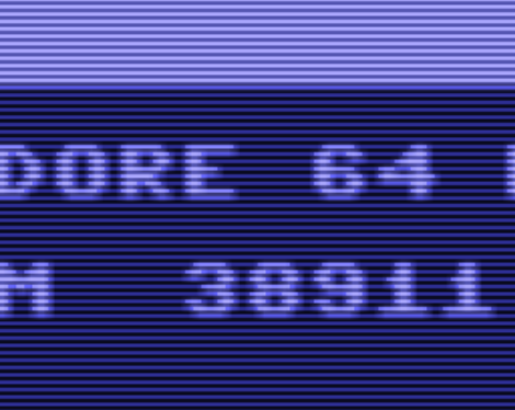
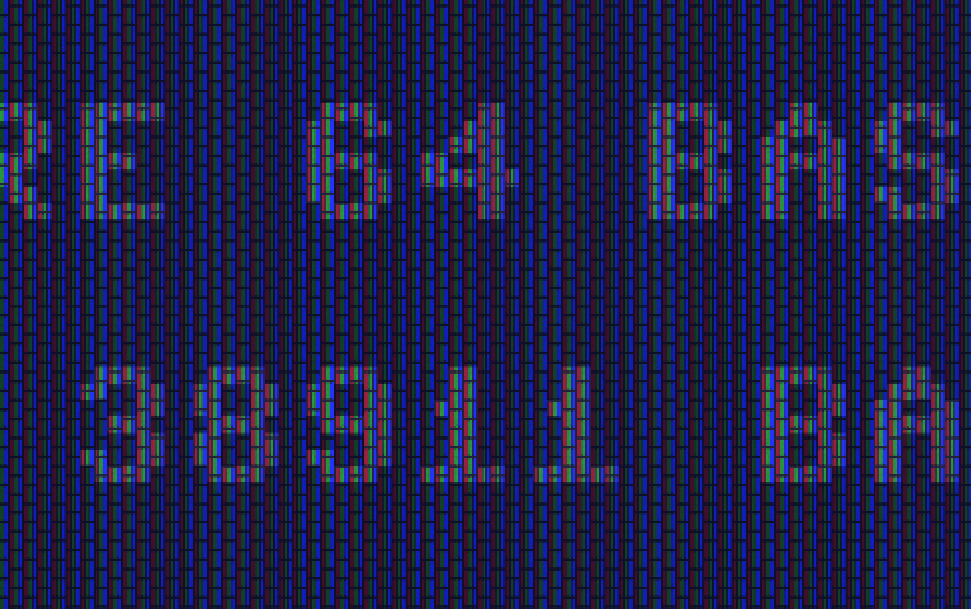
Hmm, the characters don't look right on that image. Is that an artifact of upscaling?
For blooming, it's the brighter colors that bleed, but I don't know the details. I think you have part of the work done with the blur shader.
I figured out how to parameterize the shader and hook up a knob to it: https://youtu.be/jJUE_0e8hVo
I think a single parameterized shader could do all these effects, and users could adjust various aspects to their personal preferences and screen.
jimrogerz
on 27 Oct 2018
Here's an experiment:
kernel void scanline(texture2d<float, access::read> inTexture [[ texture(0) ]],
texture2d<float, access::write> outTexture [[ texture(1) ]],
constant ScanlineParameters ¶ms [[ buffer(0) ]],
uint2 gid [[ thread_position_in_grid ]])
{
// Sample screen texture for half the upsampled row and make the other half black
float4 result = gid.y % SCALE_FACTOR < 2 ? inTexture.read(gid) : float4(0, 0, 0, 0);
// Take a blurred sample. Not a proper blur. Scale by color intensity. Supposed to be a bloom effect
// All the blurring should be replaced by a single sample from a downsized texture
int size = 6;
float radius = size / 2;
float4 accumColor(0, 0, 0, 0);
for (int j = 0; j < size; ++j) {
for (int i = 0; i < size; ++i) {
float d = sqrt(((i - radius) * (i - radius) + (j - radius) * (j - radius)));
uint2 textureIndex(gid.x + (i - radius), gid.y + (j - radius));
float4 color = inTexture.read(textureIndex).rgba;
float intensity = (color.r + color.g + color.b) / 3;
intensity *= intensity;
accumColor += d * color * intensity;
}
}
// Arbitrarily scale down
accumColor *= .1;
// Interpolate between perfect scanlines and bloom
result = result * params.scale + accumColor * (1 - params.scale);
outTexture.write(result, gid);
}
Updated result: Use the blur filter as-is to create a bloom texture, except for the following modification to scale up brighter colors:
accumColor += weight * color * color;
Have the scanline filter add it in:
kernel void scanline(texture2d<float, access::read> inTexture [[ texture(0) ]],
texture2d<float, access::write> outTexture [[ texture(1) ]],
texture2d<float, access::read> bloomTexture [[ texture(2) ]],
constant ScanlineParameters ¶ms [[ buffer(0) ]],
uint2 gid [[ thread_position_in_grid ]])
{
// Sample screen texture for half the upsampled row and make the other half black
float4 result = gid.y % SCALE_FACTOR < 2 ? inTexture.read(gid) : float4(0, 0, 0, 0);
// Sample bloom and scale 2x
float4 bloom = bloomTexture.read(gid) * 2;
// Interpolate between perfect scanlines and bloom
result = result * params.scale + bloom * (1 - params.scale);
outTexture.write(result, gid);
}
This kills the moire patterns because the contrast between brighter colors and blackness between scanlines is eliminated by the bleed:


jimrogerz
on 28 Oct 2018
@Jim: This is really a very promising result!!
I also continued on implementing the scanline emulation as outlined above (using 8 lines for one line in the original C64 texture). I'm really curious how both approaches will look like in the end. In the final version (presumably VirtualC64 3.1), we can offer both implementations as selectable CRT filters.
This morning, I managed to get the texture data back from the GPU to CPU accessible memory (one has to use the blitter to synchronize the texture data manually). This allows us to get screenshots of the internal textures and not only of what is visible on the screen.
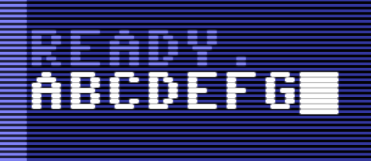
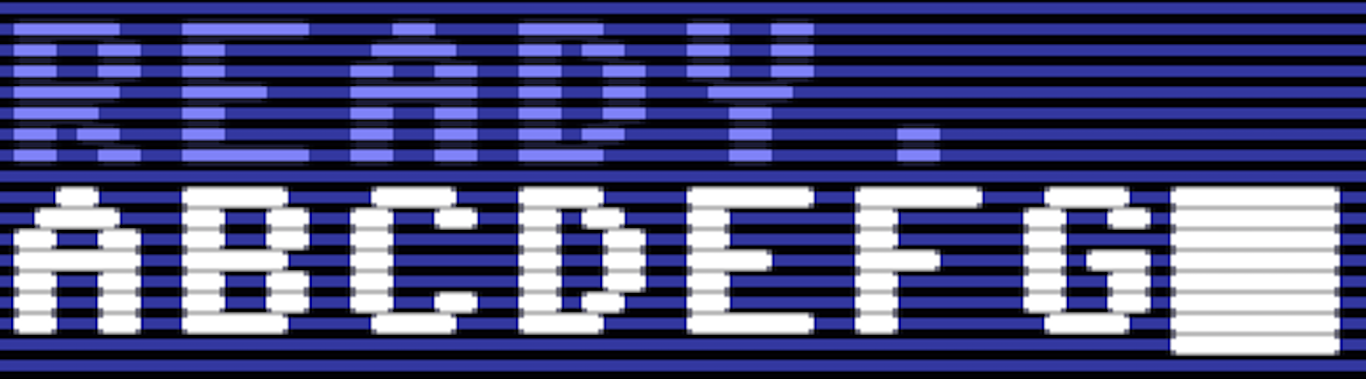
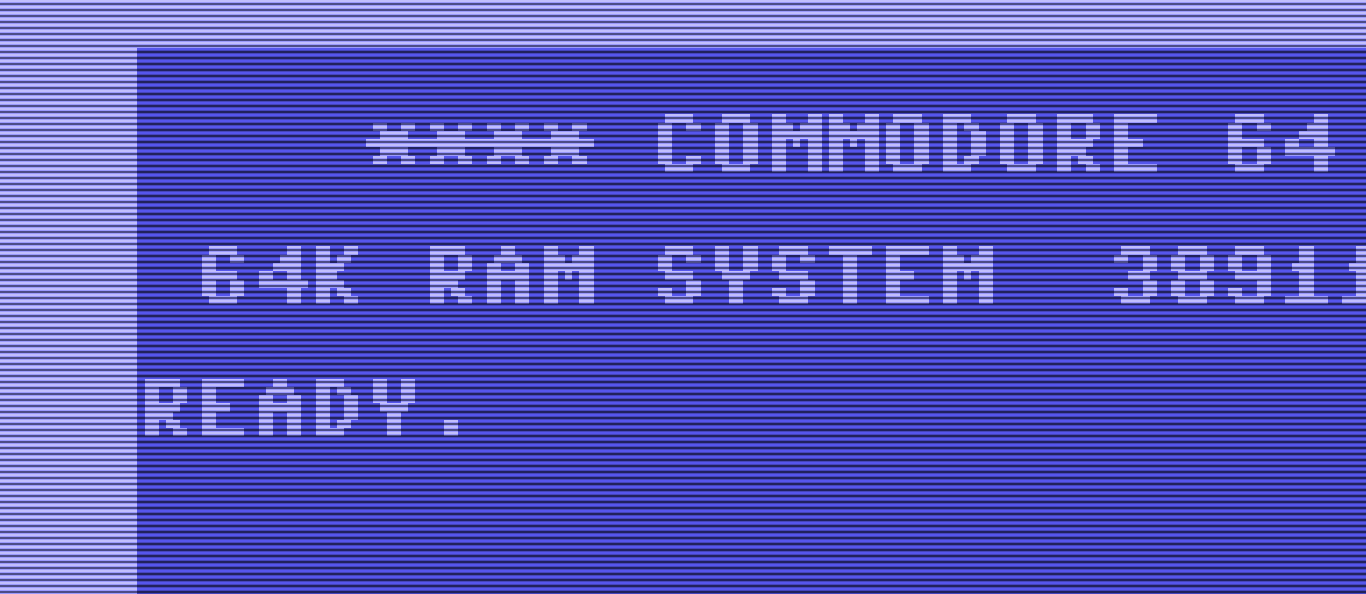
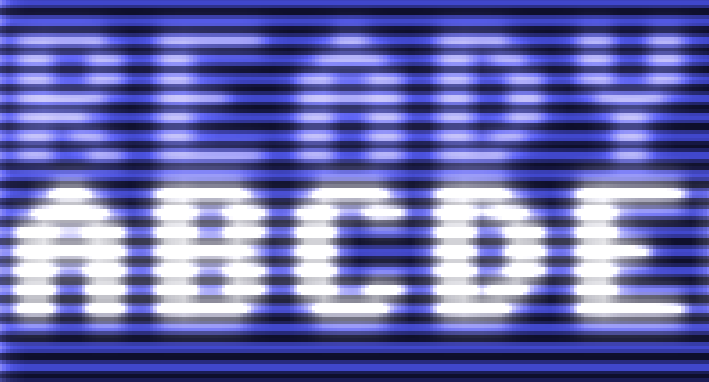
Right now, my filtered scanline textures look as follows (bloom effect is yet to come):
No upscaling:
4x upscaling:
dirkwhoffmann
on 28 Oct 2018
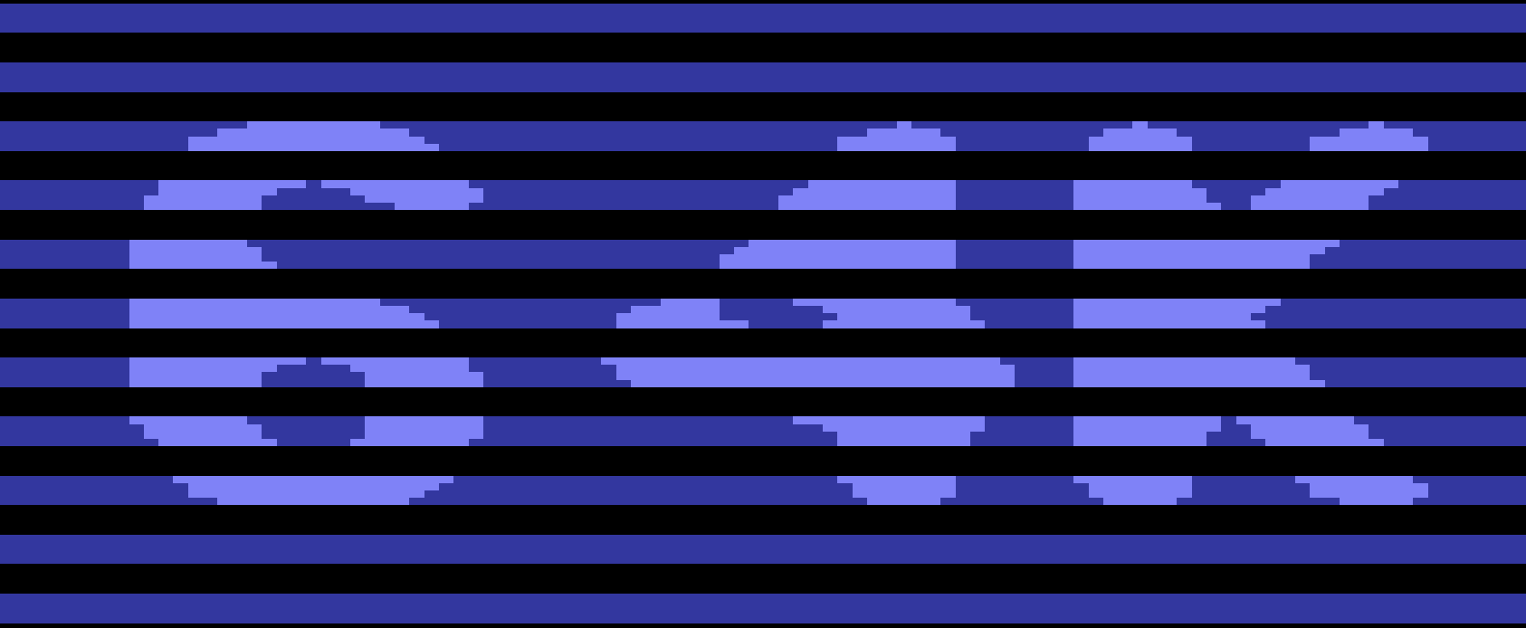
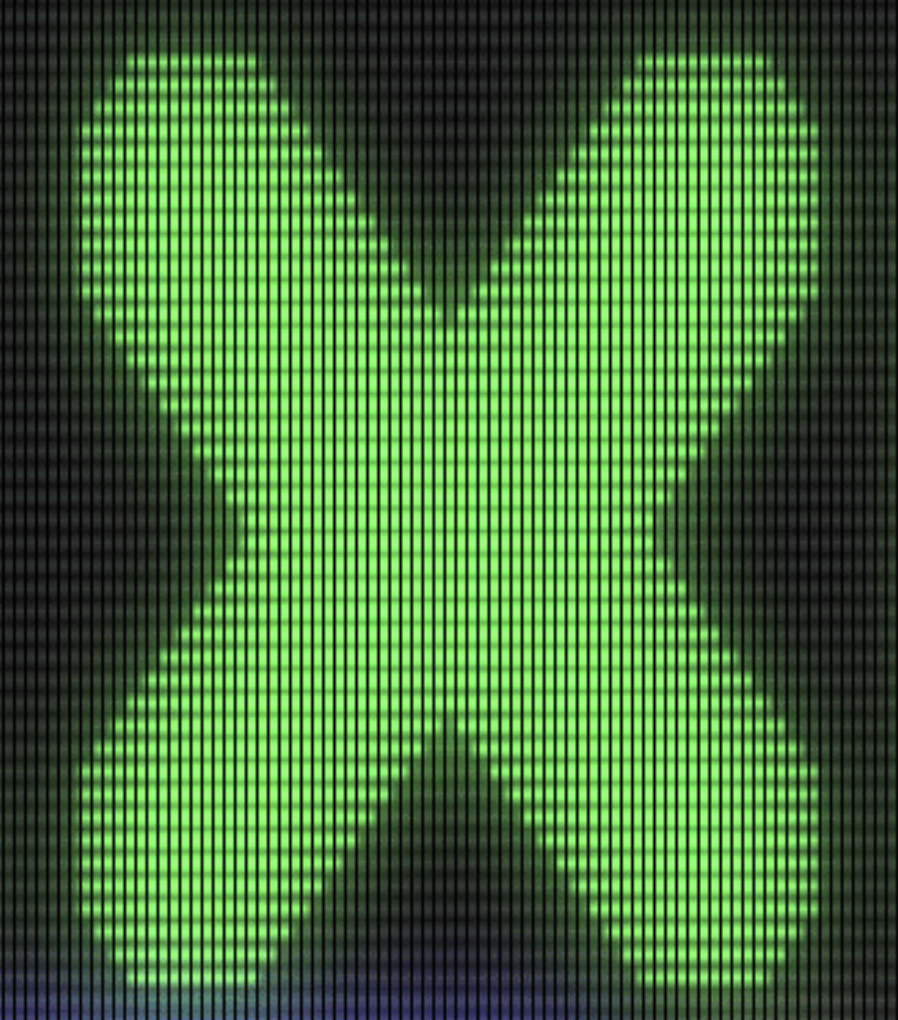
This is my first attempt to implement blooming:
Screenshot:
This is how the internal texture looks like:
As blooming factor I have used the squared luminance of the pixels in the scanline. This is the reason why the effect is large for white and small for light blue.
The effect is too little for light blue, I guess. Formulas need to be adjusted ...
dirkwhoffmann
on 28 Oct 2018
I've checked in the "texture grabbing" code into the main branch. Menu item "Save screenshot" or "Quick save screenshot" now creates a 3136 × 2144 TIFF image containing the filtered texture. This makes it possible to inspect the filter result pixel by pixel.
In the emulator settings, select "Scanline" to get Jim's original scanline filter. Select "CRT" to get my own scanline + blooming filter. I had to modify Jim's original code (from the merge request) slightly, because now, the filter result is a 4096 x 2048 texture.
dirkwhoffmann
on 28 Oct 2018
I'm thinking out loud again.
Based on Jamis Buck's well written blooming filter tutorial, we should think about the following chain:
1. Upscaler
    |
    v
2. Scanline filter (produces *two* output textures tex0 and tex1)
    |
    v
3. Gaussian blur on tex1
    |
    v
4. Superimposing tex0 and tex1

tex0 is an upscaled texture with scanlines inserted.
tex1 is a luminance scaled version of tex0. White is kept 100%, darker colors are darkened.
A dot mask effect could either be emulated inside the scanline filter (tex0) or at the end when the two textures are composed again.
Curvature would be the last thing to do. It can be emulated inside the fragment shader that writes into the frame buffer.
dirkwhoffmann
on 28 Oct 2018
Here's a reference how blooming looks on a real CRT monitor. This is what we want:
dirkwhoffmann
on 28 Oct 2018
Hi Dirk, I'm concerned about performance with the blurring, particularly on upscaled textures. I suppose once we achieve the a good result we can optimize afterward. My framerate drops from ~60fps to ~30 when blurring the 4x upscaled texture. There's techniques which speed it up considerably by splitting it in vertical and horizontal passes. I tried the current blur on the non-upscaled texture, but the blurring spanned to far, and was not good enough with smaller radius. I was considering it on a 2x upscale.
The upscaling part shouldn't effect the shape of characters. Are you using bypassupscaler or one the upscaler that tries to smooth things out?
For step 2, might not be necessary to run the bloom on the scanline texture (as an optimization). Will probably look better though, so I'm looking forward to seeing it!
jimrogerz
on 28 Oct 2018
What do you think about these controls?
SCANLINE HEIGHT: controls the vertical height of the scanline. Number of adjustments depends how how much upscaling there is, e.g. 100% (scanlines off), 75%, 50%
BLOOM SIZE: affects the radius of blurring used for bloom. Have to recalculate the blur weights as user changes knob.
BLOOM INTENSITY: Scales the bloom mix in the final texture
jimrogerz
on 28 Oct 2018
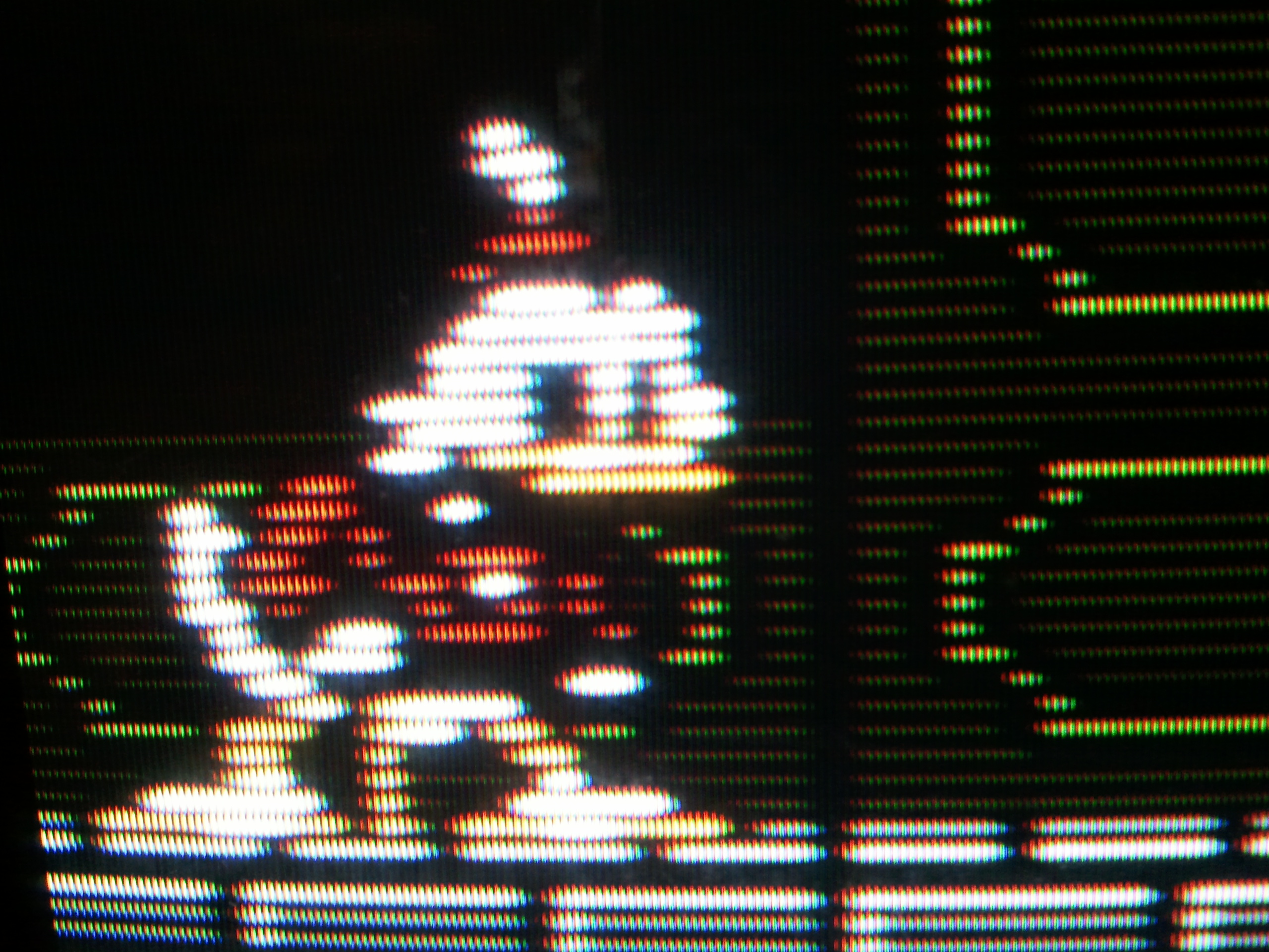
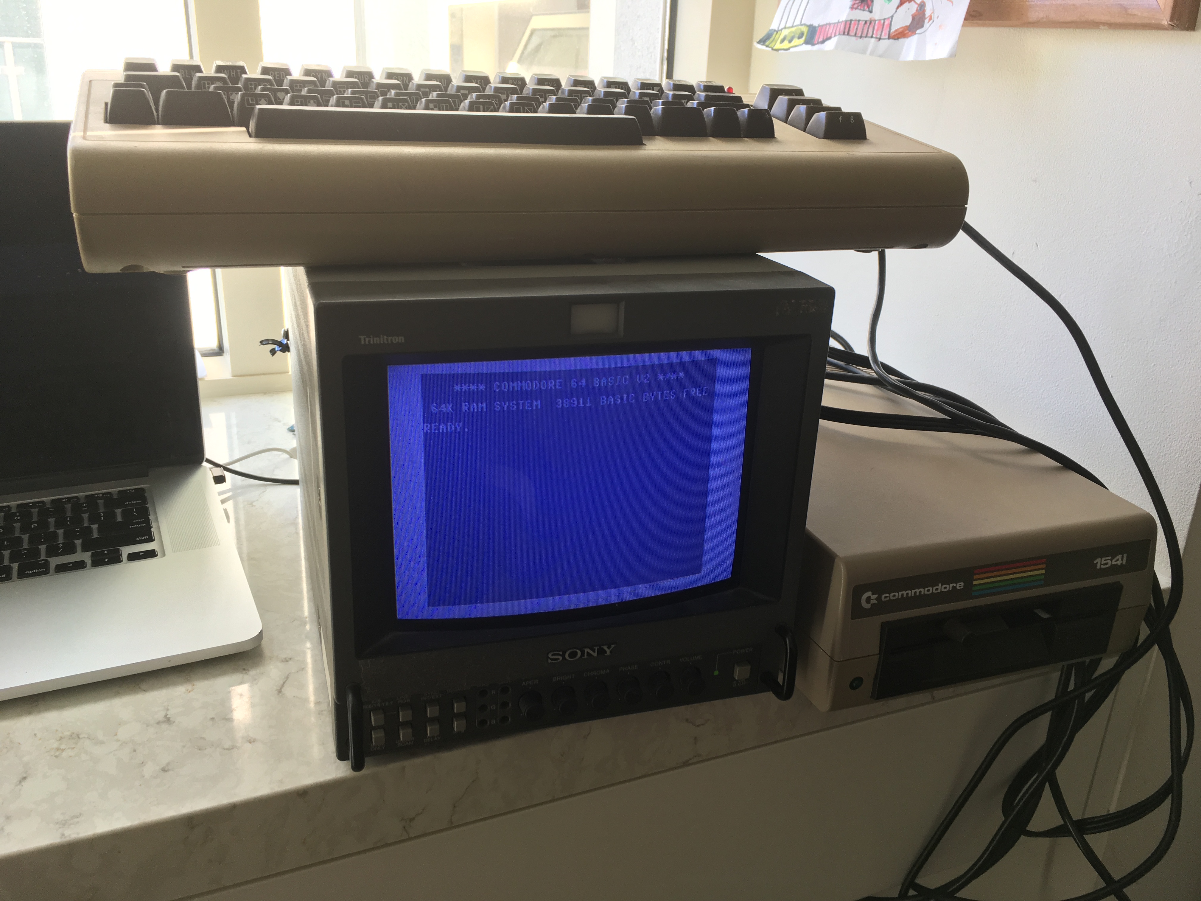
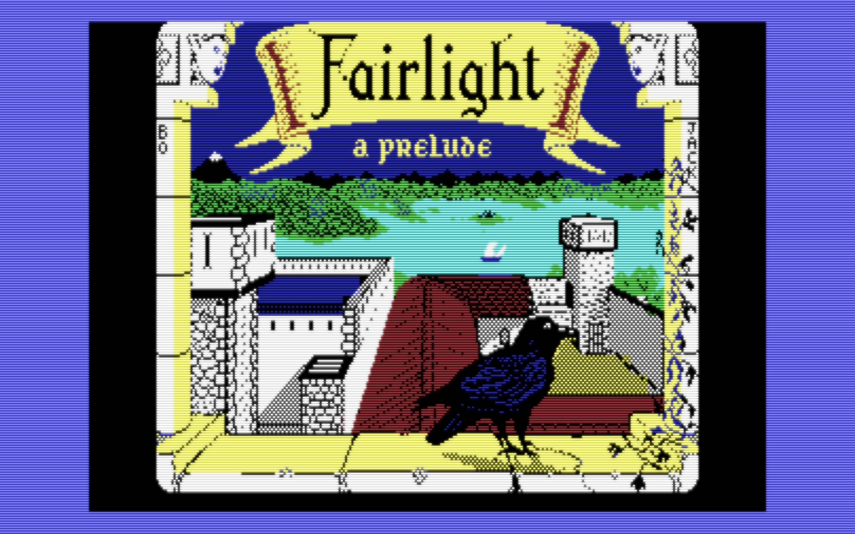
Pulled this out for inspiration. Was hoping to capture the same Fairlight image to compare to, but looks like my floppy disk is not working anymore :(
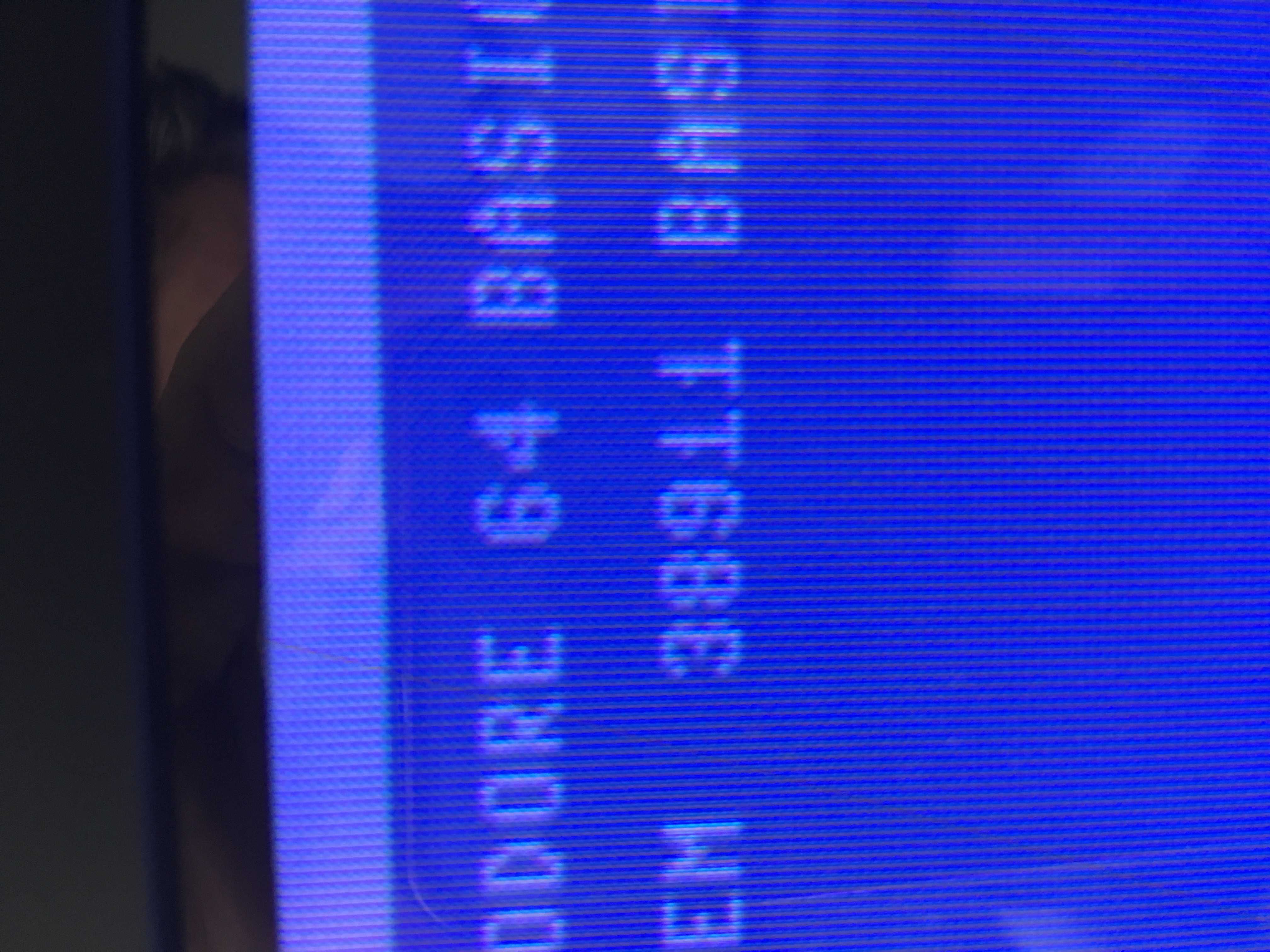
It's a decent Sony PVM monitor. Was surprised not to see any scanlines at all on the startup screen.
jimrogerz
on 28 Oct 2018
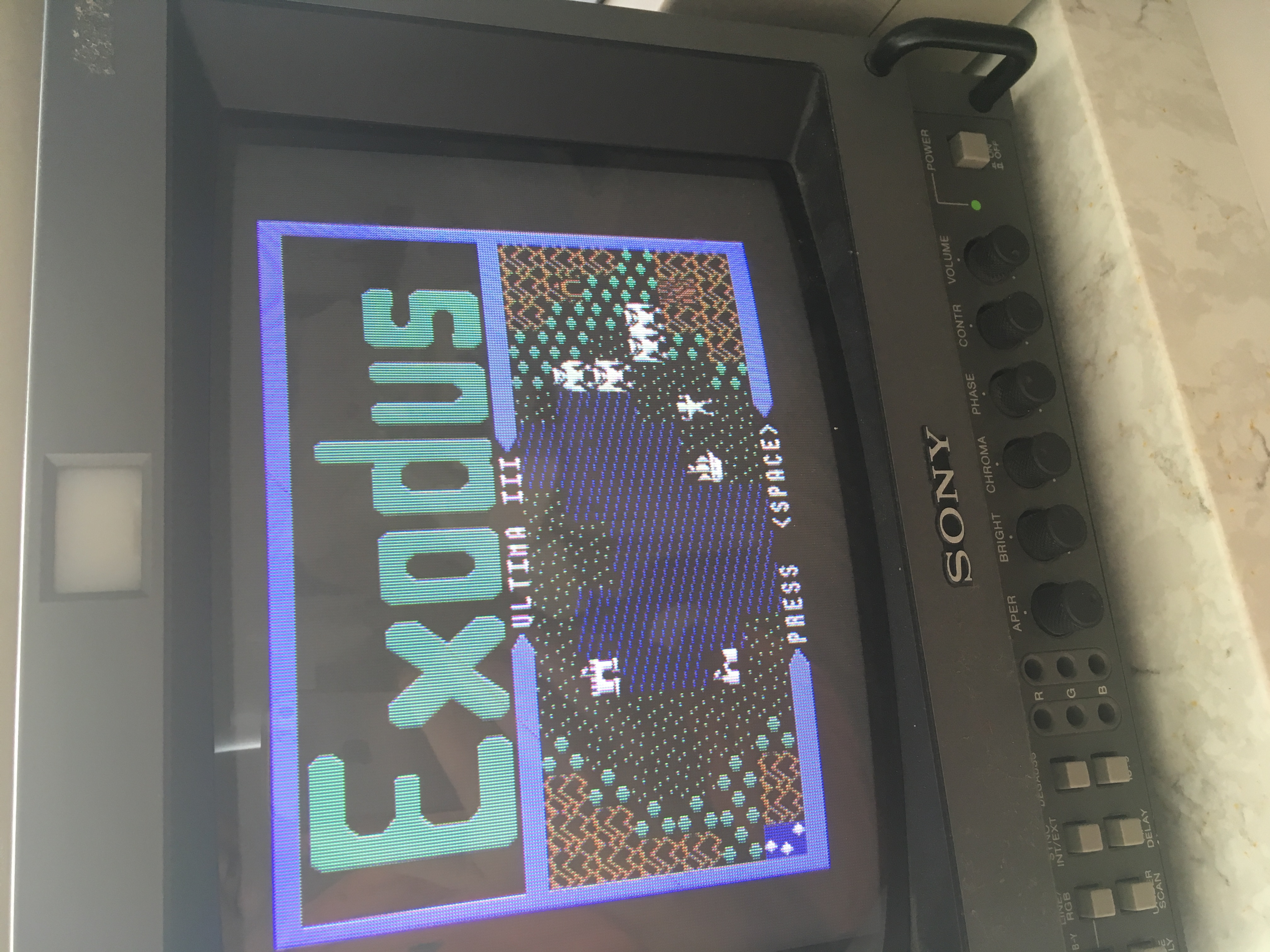
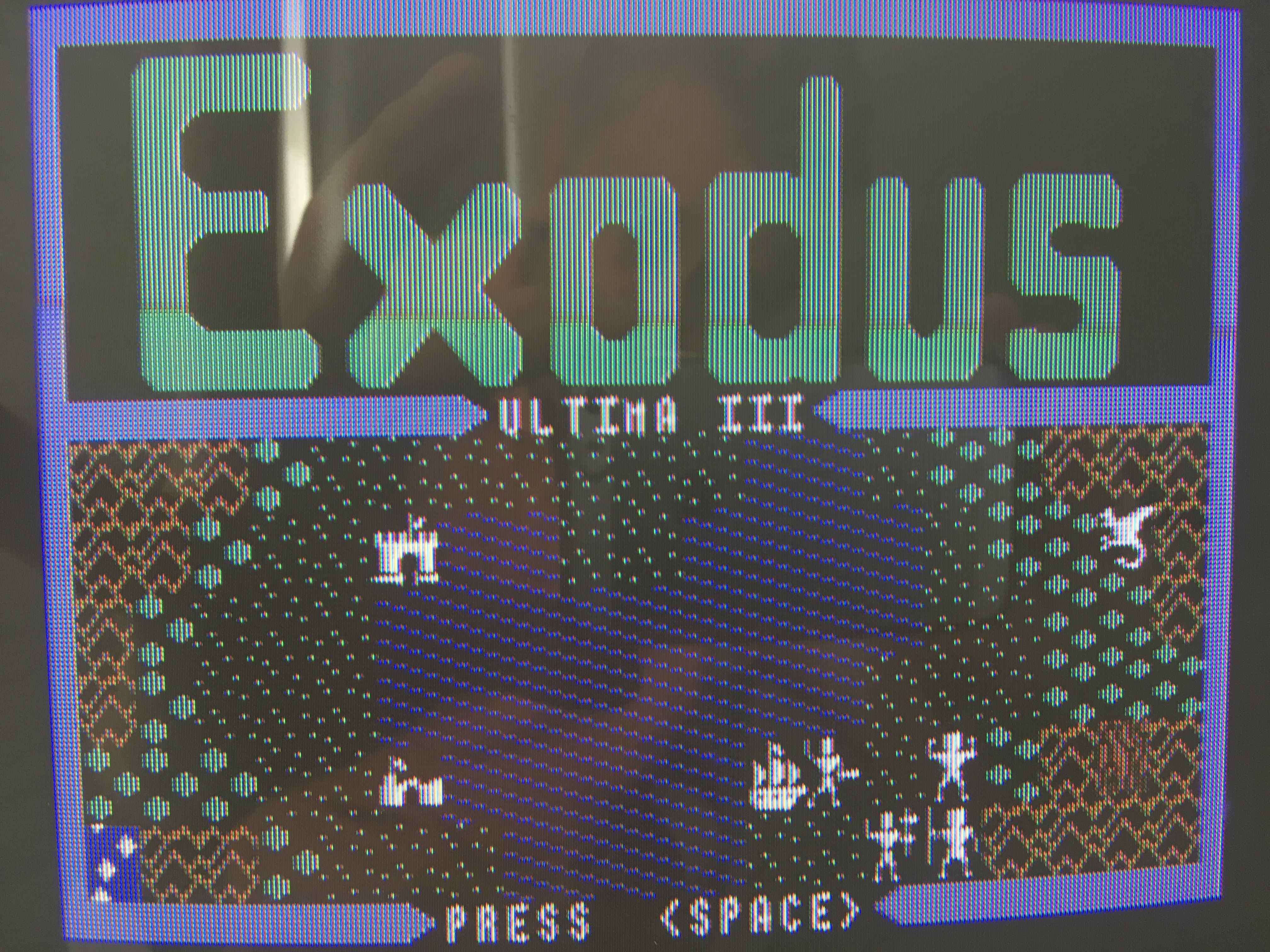
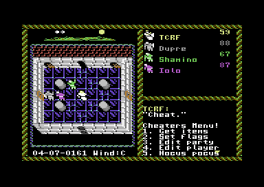
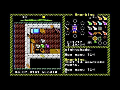
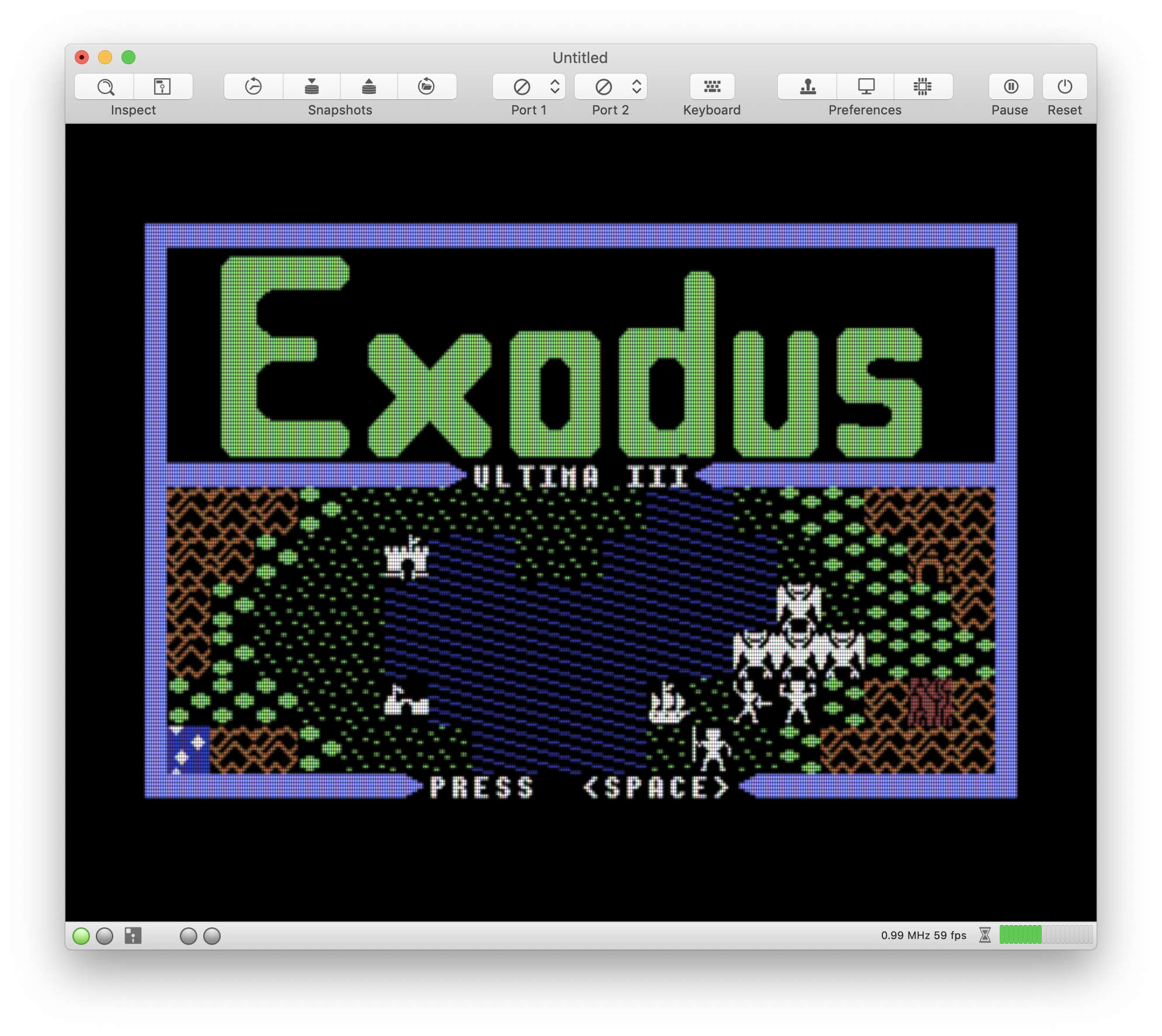
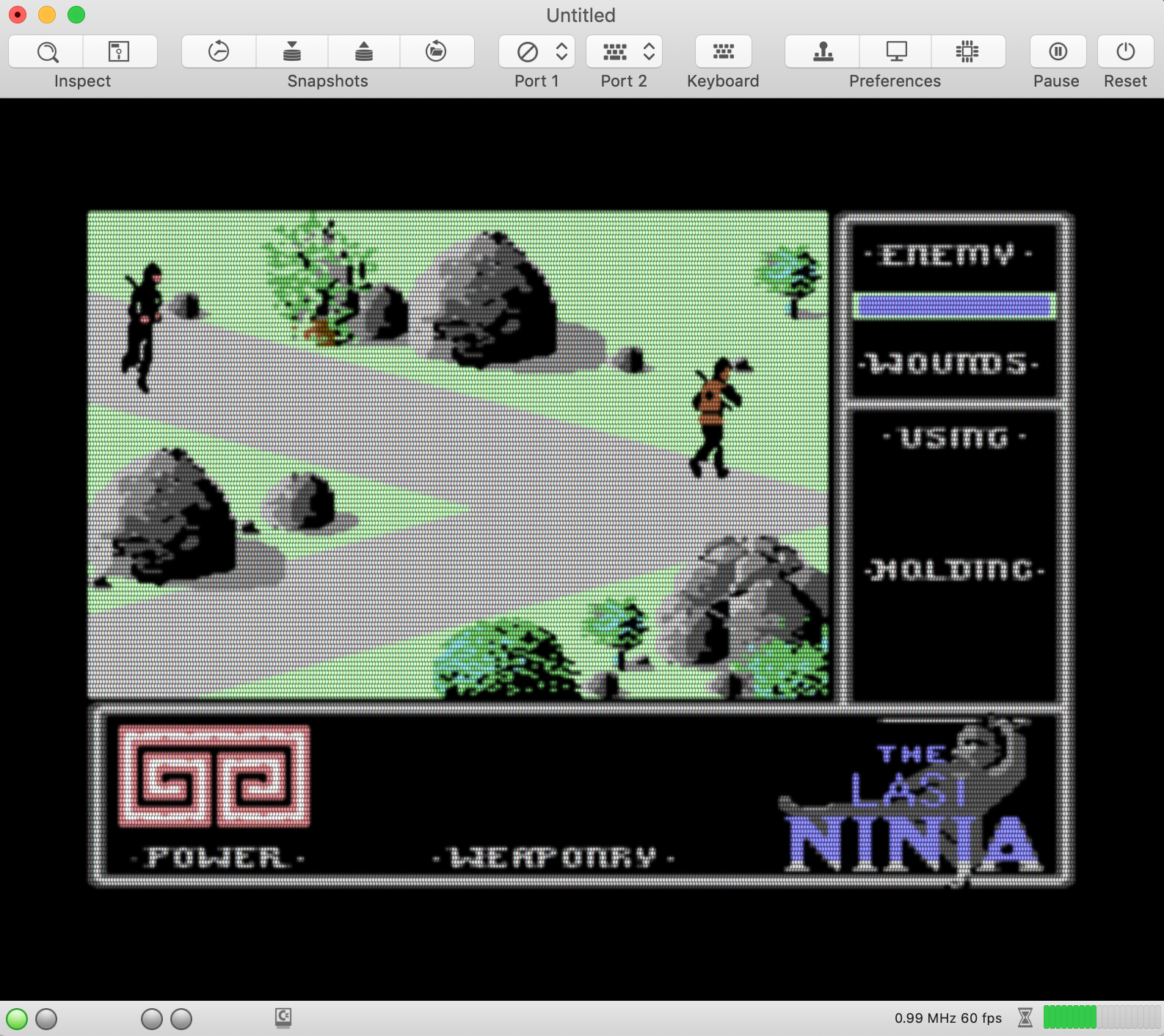
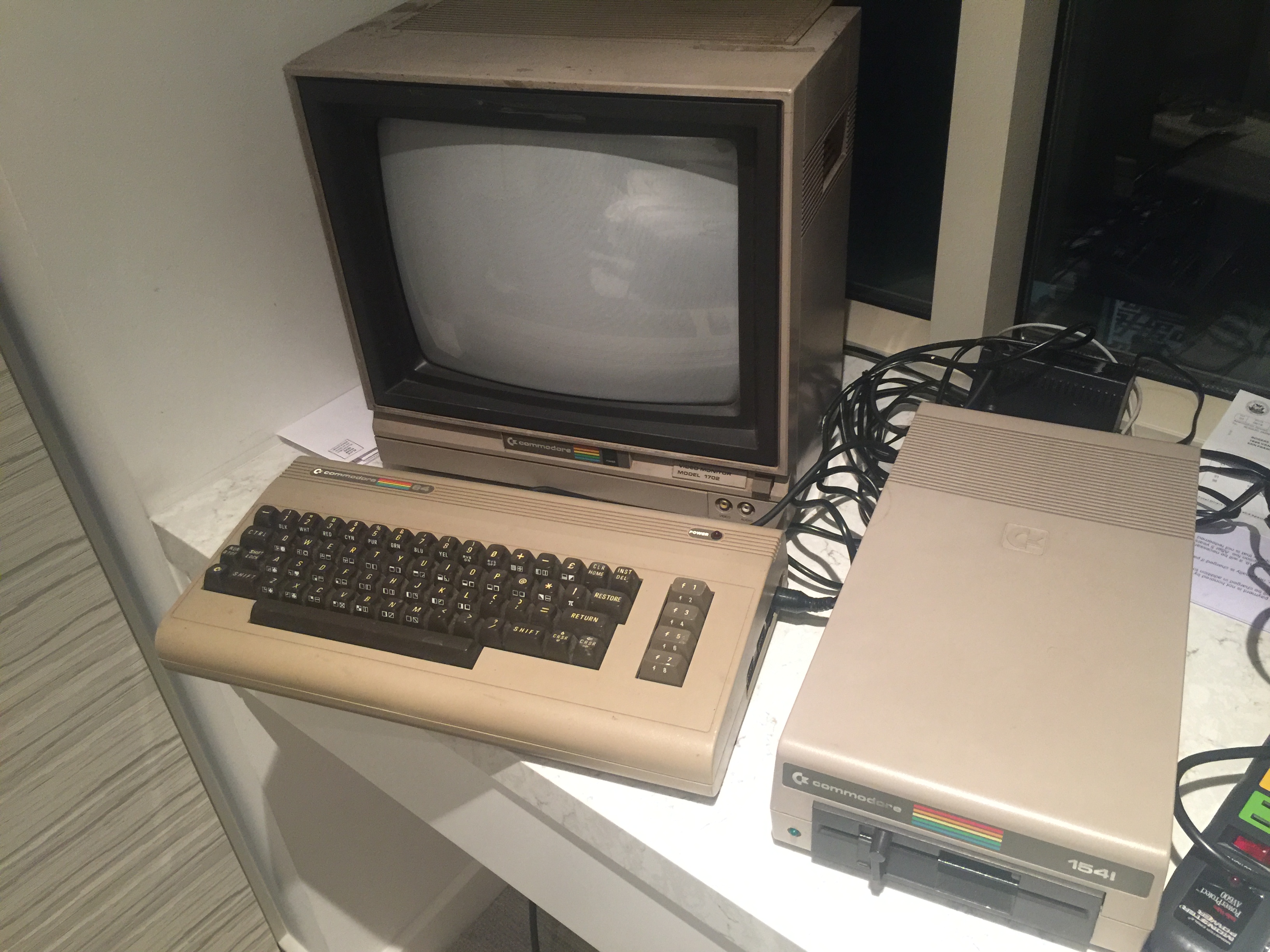
Reseated some chips and my floppy is sort of working. I can only read disks and not write. Here's an Ultima III screen:
jimrogerz
on 28 Oct 2018
Wow, a real C64 that still works 😀. Great to see this!!! I'm surprised that the drive is still working. My own C64 hasn't survived and even my Amiga is gone 🙁.
Your pictures are very helpful and might change the game for us. It seems like scanlines and scanline blooming is not the main problem at all. To get a realistic picture, we should put our focus on emulating the dot mask correctly.
Regarding the controls: I already added a control "BLOOMING" in the current code. It's just for experimental reasons. Later, if we find default values that are just good enough, we can delete the control again to keep the emulator lean.
Also you are right about the performance concern. We do have to keep in mind that the internal textures are pretty large already. The emulator shouldn't require a Mac Pro to run and emulate blooming effects that are hardly noticeable on the real thing.
dirkwhoffmann
on 29 Oct 2018
I had a brief look at the CRT royal shader. It's too complicated for me to understand the details. What I understood is that the shader is using predefined textures (besides uncountable other tricks) to emulate the dot mask. E.g.:
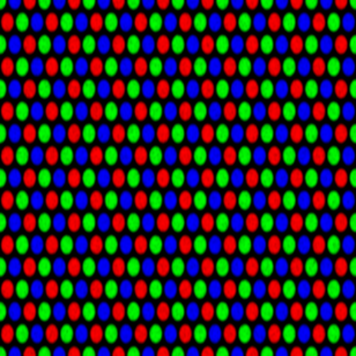
If we simply merge the upscaled texture (maybe with scanlines added) with the dot mask texture, we might be very close already. The dots in the mask texture are already blurred a little which will cause a bloom effect on the fly.
BTW, is Ultima III worth playing?
dirkwhoffmann
on 29 Oct 2018
Ultima III was a great game but its successor Ultima VI was much more ... just look at the screenshots ... without to mention the vastness and the thickness of the plot!
puleyo
on 29 Oct 2018
Yeah, at least on my monitor, the picture is dominated by the phosphor pattern. I think the scanlines are so fat you don't see the space between them. My first thought was "why are trying to emulate this **?" J/k
My monitor is a 9" trinitron tube. The trinitron has unobstructed vertical strips, which makes it easier to emulate. Wish we had a 1701 monitor or similar for reference. Here's a picture of Fairlight which looks like it was taken from a monitor: https://www.ebay.com/itm/Commodore-64-128-FAIRLIGHT-C64-ORIGINAL-disk-TESTED-Mindscape/123024745352?hash=item1ca4d8a388:g:b2YAAOSwoYdarAC8:sc:USPSFirstClass!94109!US!-1:rk:2:pf:0
I played Ultima III for months as a kid. One of my favorite RPGs. U4 is probably the best, but I haven't played it.
jimrogerz
on 29 Oct 2018
Later high end PVMs and many Trinitrons did not have traditional scanlines, they had several hardware methods for evening out and improving even the most low quality image signals. We have a local arcade here, and I'd say about 50% of the cabs have scanlines, the other 50% have dot masks that negate the scanlines. There were many different CRT dot masks, but I think you'd find that scanlines is what most people generally accept as a classic CRT look. Its also easier to simulate :)
Here a video of a Commodore 1084s and its scanlines:
https://www.youtube.com/watch?v=fgX0m25OZeQ
(edit: I'm no expert by the way, just going on from what I've seen online and from my memory of owning a Trinitron and staring at it intensely. I own a 1084s at the moment, but I think mine is a different brand of CRT than the youtube vid.)
superrune
on 29 Oct 2018
Hi Dirk, I haven't looked at the CRT royal shader, but it should be super easy. We just need to sample the phosphor texture (repeating) at the right scale, and multiply it with the previous stage. I'm trying it now.
jimrogerz
on 30 Oct 2018
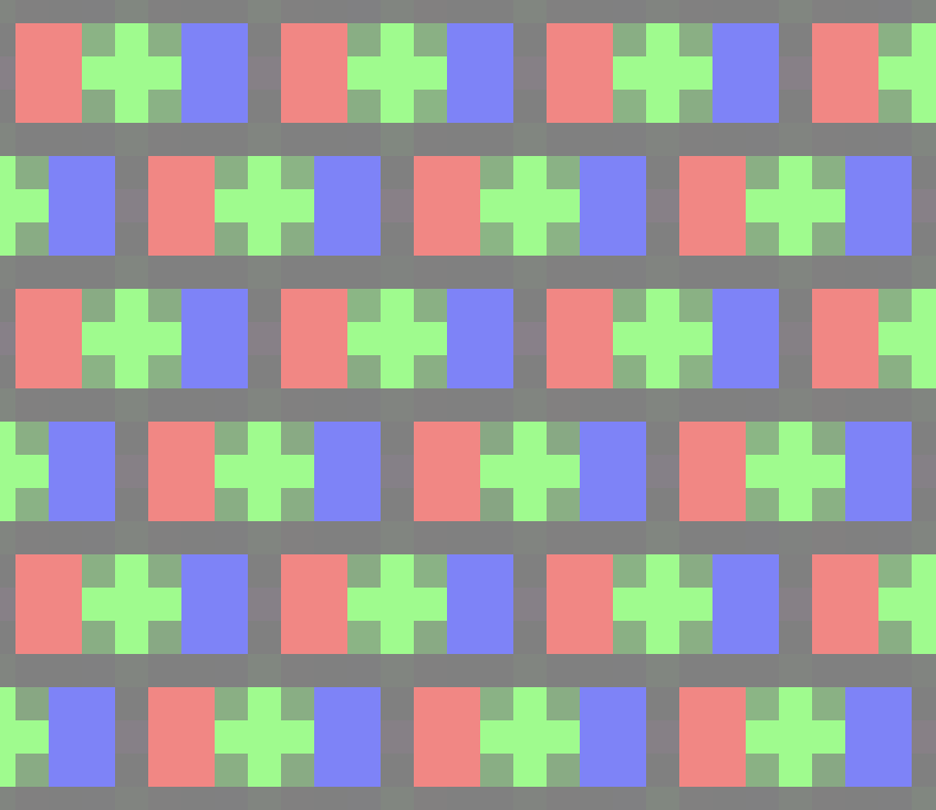
Here's a test with this trinitron pattern:
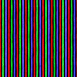
It's applied to an unfiltered screen (no scanlines). I adjusted the scale so there were about 11 sets of the pattern across the "64":
Also had to bump the output resolution to 8192x8192. There's a little moire going on, but bloom should take care of that.
jimrogerz
on 30 Oct 2018
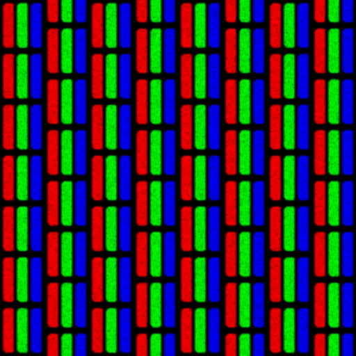
Tried it with the other pattern posted earlier. Bumped output to 16384x16384. I think I would do this programmatically instead of sampling from another texture.
jimrogerz
on 30 Oct 2018
Hi Jim. I think, the results are very promising! Here are some ideas to improve it further:
I think it would be a nice feature if we offered different dot masks to the user (either directly selectable or selectable via a monitor type (CRT Trinitron or something like that) ). If we do this, using dot mask textures seems to be the right way to go. In addition, one gets some effects for free. E.g., one could think about blurring the dot masks in photoshop a little more.
To avoid the Moiré issues, me might have to apply the dot mask in the fragment shader, at the end of the processing chain. The Moiré effect should be much less if the dot mask texture is not accessed directly, but via a texture sampler of type "linear". A texture sampler is already passed to the fragment shader, so we could just pass a second one along with the dot mask texture (or maybe the first sampler can be reused, I'm not sure about that).
To get a realistic crt shader, there seems to be no way around blurring the texture. Apple offers a gaussian blur filter as part of their "performance shaders". I guess it's a two pass shader optimized for speed. If we apply the apple shader on the upscaled texture or the upscaled texture with scanlines added, performance might be still good. I never used Apple's prebuild shaders before, but Jamis Buck did in his blooming effect tutorial.
dirkwhoffmann
on 30 Oct 2018
Hi Dirk, yes I was thinking the same thing about having a dropdown of pixel patterns. Btw, my test was using linear sampling. A fragment shader is not required. Pass the texture in like this:
texture2d<half, access::sample> phosphorTexture [[ texture(2) ]],
Sample like this:
    // Sample from phosphor image
    constexpr sampler texSampler(coord::normalized,
                                 address::repeat,
                                 filter::nearest);
    float2 uv = float2(gid.x / 20.0, gid.y / 20.0);
    half4 phosphorSample = phosphorTexture.sample(texSampler, uv);

    // Multiply outColor by phosphor (scaling up to prevent moire)
    outColor *= saturate(phosphorSample + .5);
The scaling of the final image to the screen is affecting the final output. Do you know how to make the output texture match the native screen resolution?
Started experimenting with adding scanlines to the mix, and it didn't work well. It is hard to distinguish them from the phosphor mask.
jimrogerz
on 30 Oct 2018
I did some experiments with overlaying the round dot mask texture from CRT royal with the upscaled C64 texture in the fragment shader.
It's not really a master piece yet. It's more like 😲🤢 with Moiré effects all over the place.
"to make the output texture match the native screen resolution". Is your plan is to adjust the internal texture size dynamically to match the final screen pixels one by one? But then, wouldn't we face the Moiré issues inside the texture generation code?
One implementation issue is to get access to the frame buffer size (size of the Metal view in native Mac screen pixels) inside the GPU code. It seems like that these values need to be passed in manually. One has to setup a buffer (in method MetalScreen::reshape() ) with the contents of variables layerWidth and layerHeight.
It might help to emulate the dot mask in the fragment shader based on the Mac screen resolution and not based on the texture resolution. As a drawback, the size of the dot mask would vary between Macs and wouldn't match the C64 to 100%. But it should avoid all Moiré effects that are created by the dot mask. One could do the same thing with scanlines. Hence, instead of displaying a CRT-C64 on a TFT-Mac, we would display a TFT-C64 on a CRT-Mac.
dirkwhoffmann
on 30 Oct 2018
By native screen resolution, I mean the Mac's full screen resolution. My plan was mock the CRT pattern aligned exactly to the screen pixels. I bet there will still be Moire issues, and probably issues with the apparent size of the mask.
jimrogerz
on 31 Oct 2018
Just one more idea regarding scanlines and dot masks:
- I think scanlines should be part of the texture (as they are right now), but the dot mask should not. Why? Because the number of scanlines in independent of the emulator's window size, but the dot mask is not. A typical dot mask has a dot pitch of about 0.26 mm to 0.28 mm and we should try to mimic these values on the Mac screen (hence, we emulate more dots for a bigger emulator window). This should get us around the Moiré pattern problem, because we can then represent each dot with the the same amount of pixels (the number of pixels needs to be calculated from the Mac screen parameters to get a realistic dot pitch around 0.27 mm).
When I get some free time again, I'll try to implement the following processing chain:
- Get the C64 texture from the emulator and apply the upscaler
- Apply the scanline filter (which is already there) to the upscaled texture and apply a bloom effect. The bloom effect could be emulated nicely (I think) with a slightly modified version of Jim's vertical Gauss preprocessing shader (which is already there).
- Perform the horizontal Gauss shader stage (which is already there).
- Multiply the bloomed texture with the dot mask texture in the fragment shader with a dot pitch of roughly 0.27 mm.
dirkwhoffmann
on 1 Nov 2018
Some useful information about how the dot pitch is measured:
dirkwhoffmann
on 1 Nov 2018
Hmmm, I don't really get it. I did an experiment with the following code in the fragment shader:
 uint posx = uint(vert.position.x);
 uint posy = uint(vert.position.y);
 if (posy % 2 == 0) {
         color = float4(1.0,0.0,0.0,0.0);
     } else {
         color = float4(0,0,0,0);
     }
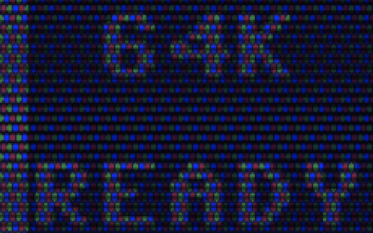
In the fragment shader, 'position' contains the position in pixel coordinates, so the pixel rows on the Mac screen should be alternating between red and black. Unfortunately, I still get Moiré patterns:
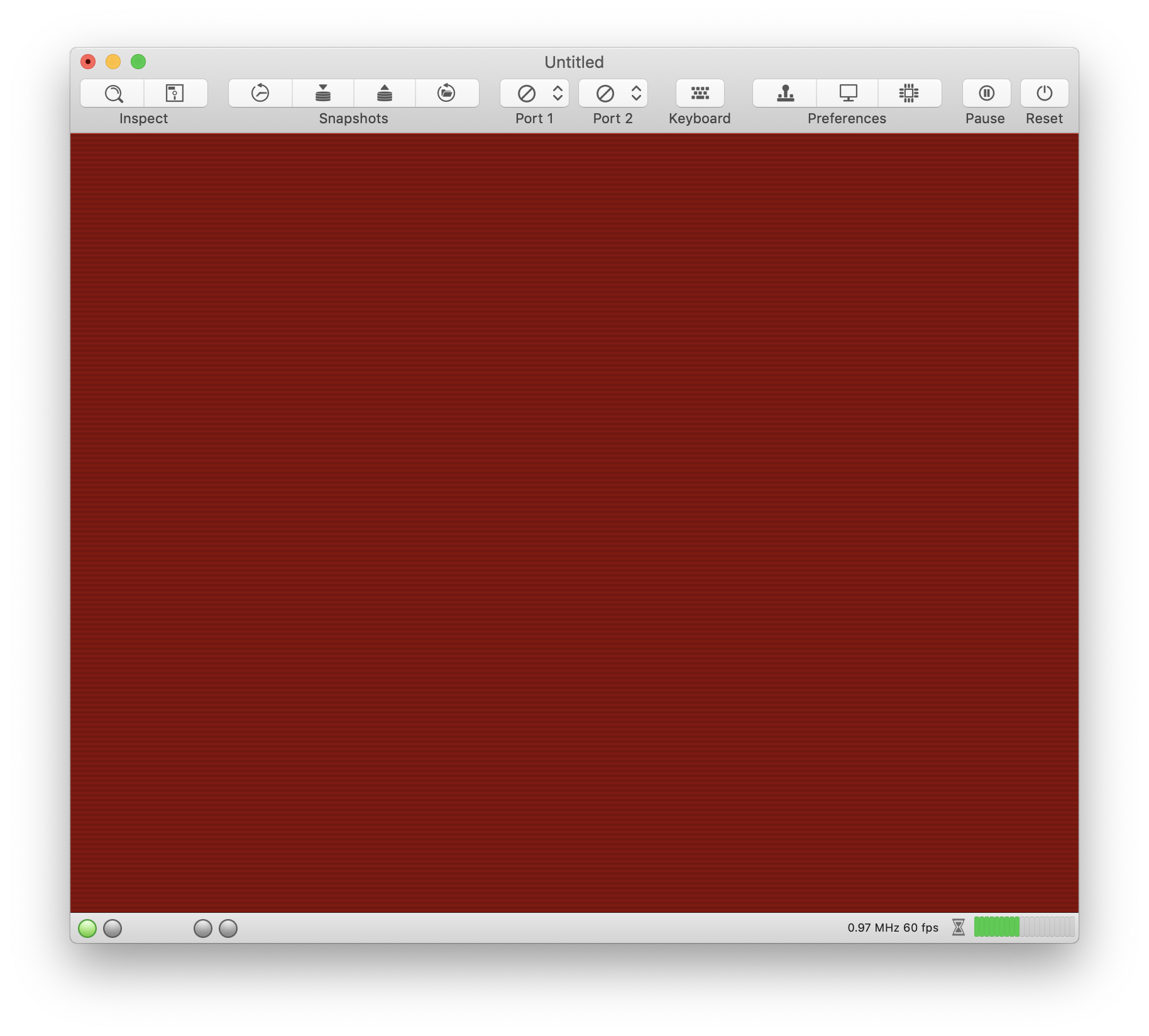
But when I take a screenshot and enlarge it, I get rows that alternate perfectly.
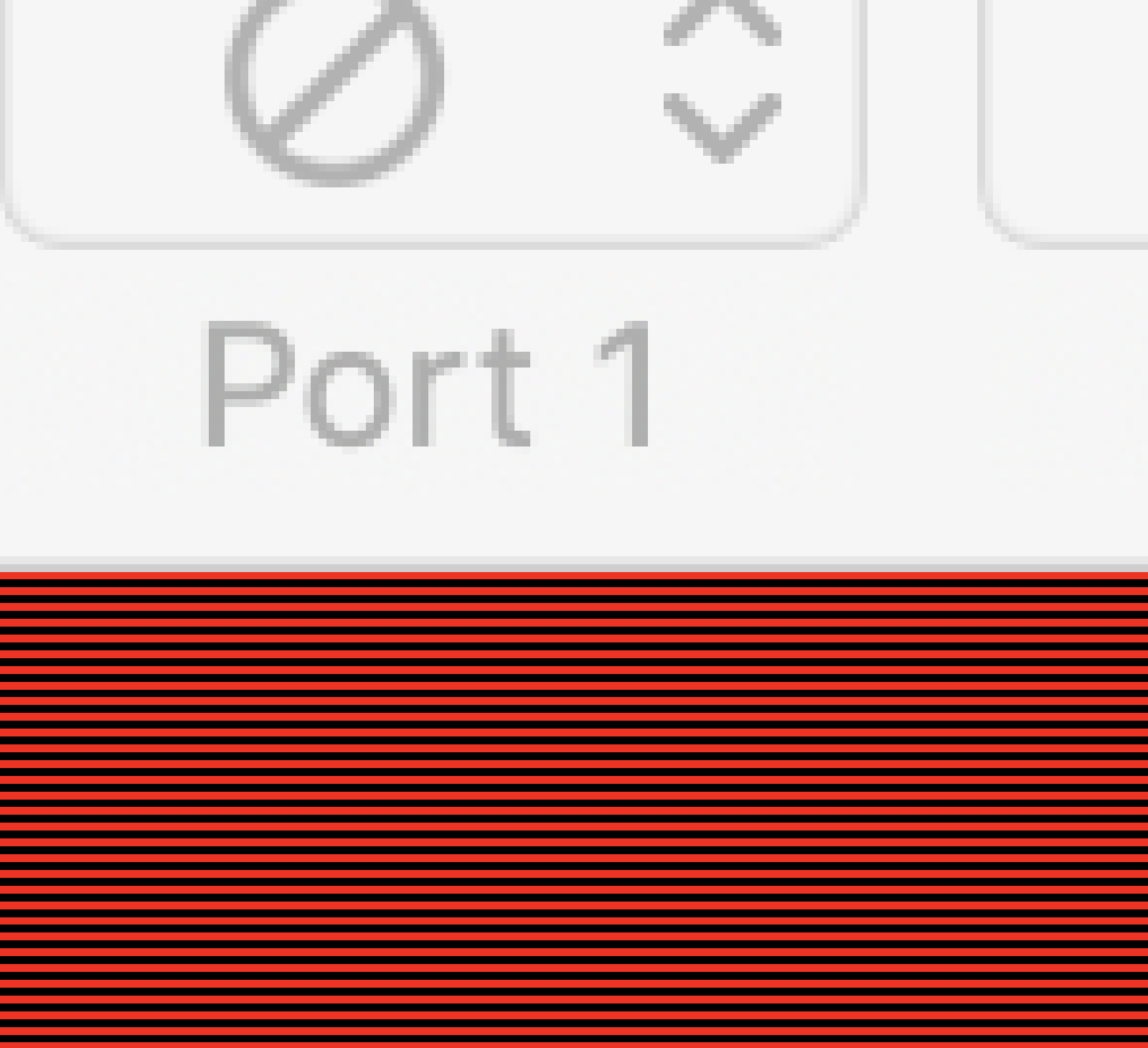
There must be another post-processing stage we cannot influence 🤔.
dirkwhoffmann
on 1 Nov 2018
Yeah, I tried setting the texture resolution to my screen resolution, but there appeared to be some scaling. I assumed the texture pixels would be mapped 1:1 with screen pixels, but apparently not. Maybe something going on with the zoom or the 3d pipeline?
jimrogerz
on 2 Nov 2018
Here's my latest results, building off https://github.com/dirkwhoffmann/virtualc64/pull/453. I created a scanline upscaler which takes the 512x512->1024x1024. It looks like this with no filter:
Next I made a bloom filter. It takes the 512x512 blur texture and adds it to the 1024x1024 upscaler output. It is hooked up to the BLOOM knob for scale. It looks like this:
It's a 1024x1024 output, and runs 60 fps.
jimrogerz
on 2 Nov 2018
Hi Jim. I think the code cleanup part is fine (texture sizes). I didn't merge in the code yet, because I think we have to modify some stuff (again).
Firstly, I (think I) managed to solve the Moiré issue with my red/black stripe pattern. I replaced method
   func reshape(withFrame frame: CGRect) {

        if let scale = NSScreen.main?.backingScaleFactor {

            track("backingScaleFactor = \(scale)");

           var size = bounds.size
            size.width *= scale
            size.height *= scale

            metalLayer.drawableSize = drawableSize
            reshape()
        }
    }
by
func reshape(withFrame frame: CGRect) { reshape() }
Background: It shouldn't be necessary to set 'metalLayer.drawableSize' manually. At least Apple says so: "By default, a layer vends textures sized to match its content—that is, this property’s value is the layer’s bounds size multiplied by its contentsScale factor."
Interestingly, my code assigns the exact same values to drawableSize (if I read my debug output correctly), so in theory, nothing should be different. Maybe, the metal API automatically adds a post-processing resizing phase if this value is overwritten manually, independent of the assigned value.
Anyway, with the new code, I can draw the dot mask without any Moiré effect. Woohoo!
Upclose:
There are a couple of issues left though:
In my experiment, I superimposed the dot mask with a 100% white background. The problem is that we loose too much luminance (even with the 0.5 added). Hence, I think we need to implement some smart scaling that keeps the luminance of a pixel constant.
When I superimpose the dot mask with the upscaled texture with scanlines added, I get Moiré patterns caused by the scanlines. Therefore, I have to take back what I said about the scanlines belonging to the texture. I think we have to add scanlines after rasterization (like the dot mask) in the fragment shader.
Yes, upscaling must be the first thing to happen (i.e., before blurring).
So we should probably consider the following processing chain:
- First compute shader: Upscaler (512x512 -> 2048x2048)
- Second and third compute shader: Two-phase Gaussian blur (2048x2048 -> 2048x2048)
--- The GPU performs rasterization here
- Fragment shader: Add scanlines and apply dot mask.
There is another issues about dot mask though:
I looked up the dot pitch of the Commodore monitor which is 0.42 mm. A 15" Mac book screen has a width of about 33 cm. This means that we need to emulate about 786 dots in the dot mask. The CGLayer shows a width of 1548 on my machine. This means that we only have 2 pixels (maybe 4 if we can address Retina pixels separately) for a single dot. This makes the dot mask textures somewhat useless, or am I missing something?
dirkwhoffmann
on 2 Nov 2018
P.S.: Here is my fragment shader code:
fragment half4 fragment_main(ProjectedVertex vert [[stage_in]],
                             texture2d<float, access::sample> texture [[texture(0)]],
                             texture2d<float, access::sample> texture1 [[texture(1)]],
                             sampler texSampler [[sampler(0)]])
{
    constexpr sampler sampler1(coord::normalized,
                              address::repeat,
                              filter::linear);

    uint posx = uint(vert.position.x);
    uint posy = uint(vert.position.y);

    float2 uv = float2(float(posx % 64) / 64.0 , float(posy % 64) / 64.0);
    // float4 color = texture.sample(texSampler, vert.texCoords);
    float4 color = float4(1.0,1.0,1.0,0.0);
    float4 phosphor = texture1.sample(sampler1, uv);

    color *= saturate(phosphor + 0.5);

    /* Stripe experiment
    if (posy % 4 == 0 || posy % 4 == 1) {
        color = float4(1.0,0.0,0.0,0.0);
    } else {
        color = float4(0,0,0,0);
    }
    */

    return half4(color.r, color.g, color.b, vert.alpha);
 }
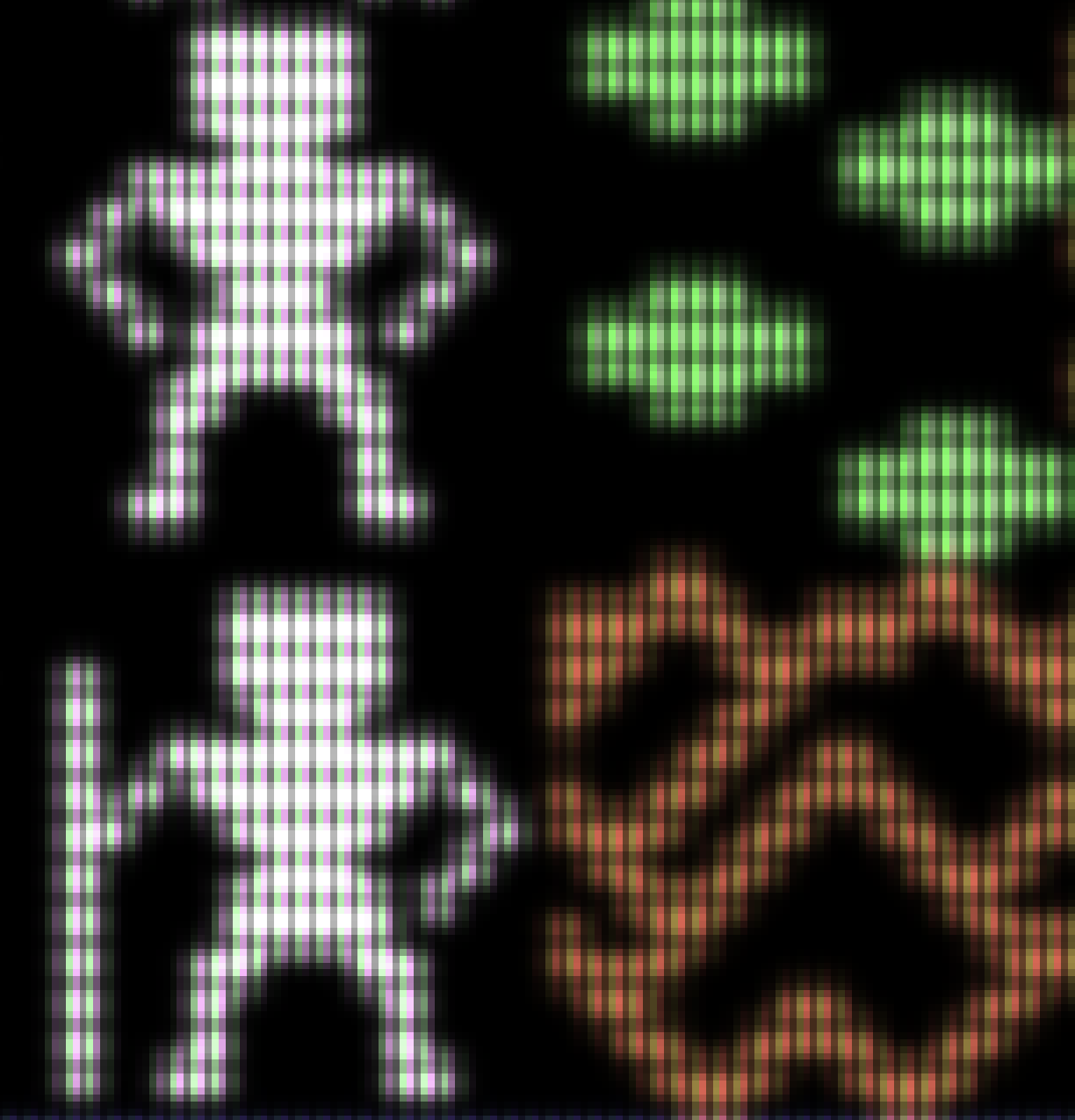
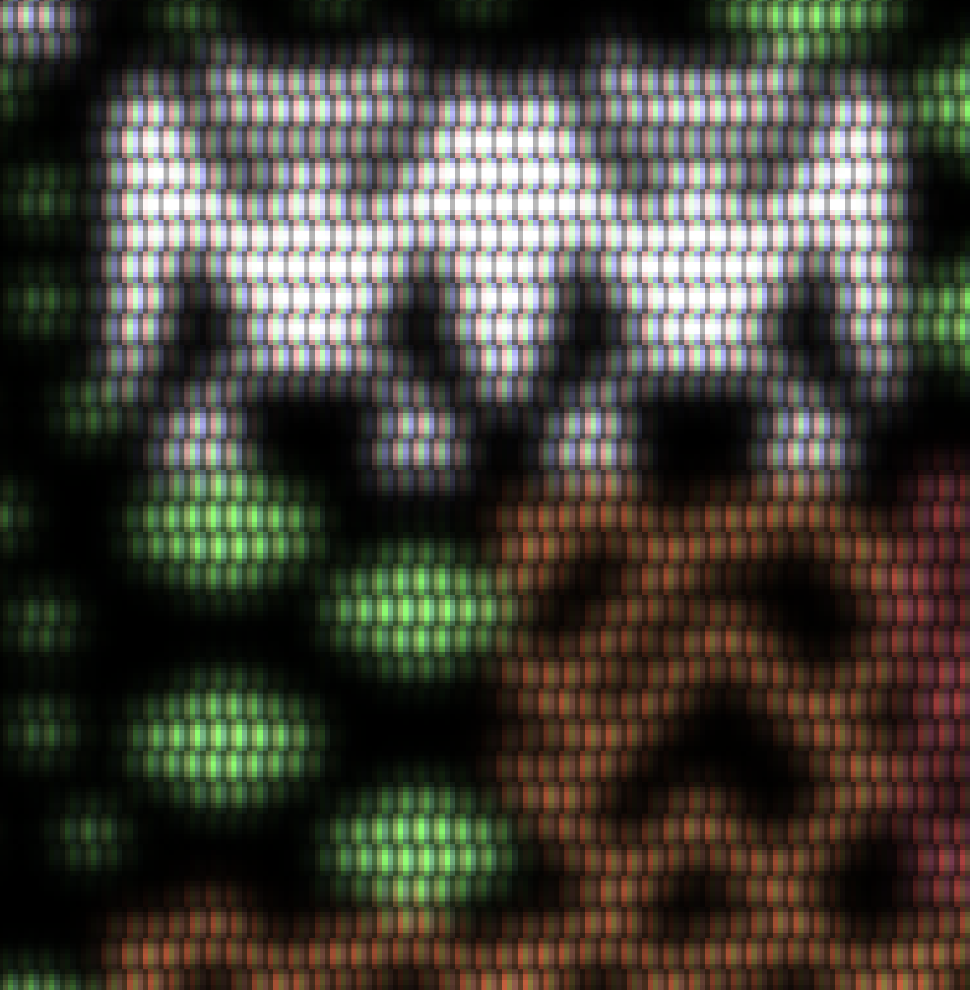
Now I'm pretty sure that we have to emulate CRT effects within the fragment shader (no Moiré patterns any more 😎). I took some of the CRT-pi shader stuff, merged it with my own stuff and came up with the following result:
Upclose:
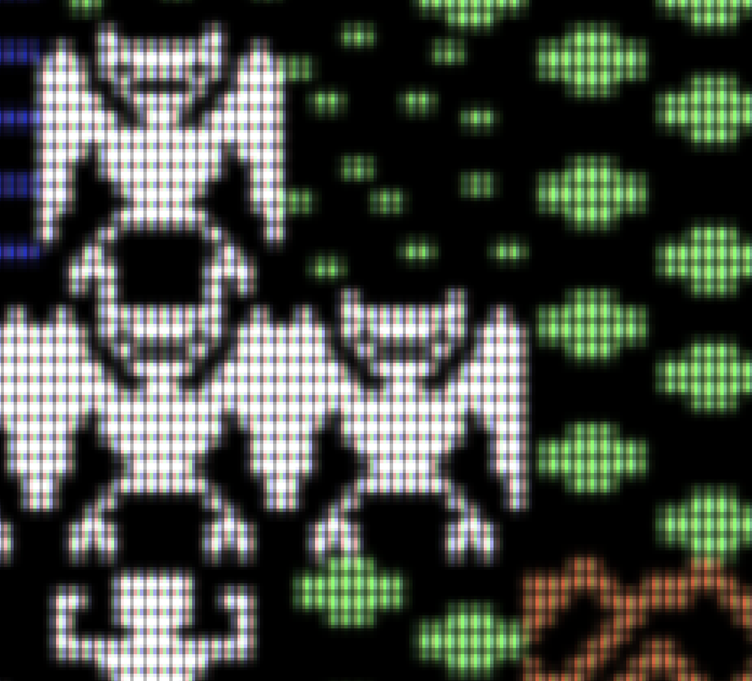
The monsters look scarier with the new CRT filter, don't they? 🤔
If we go with this (or a similar solution), we could offer the following options to the user in the emulator prefs:
Upscaler: [ None, 2x, 4x ]
Blur: [ None, Medium, Strong ]
Effect: [ None, Crt (Mask type 1), Crt (Mask type 2) ] *
- Mask type 1 and type 2 as emulated in the crt-pi filter (they have special names which I don't remember at the moment).
If a Crt effect filter is selected, one could enable controls for the following parameters (these are the parameters used in crt-pi):
MASK_BRIGHTNESS
SCANLINE_WEIGHT
SCANLINE_GAP_BRIGHTNESS
BLOOM_FACTOR
My experimental code is located on branch CRTpi. Right now, it only works properly when Gaussian blur is selected.
dirkwhoffmann
on 2 Nov 2018
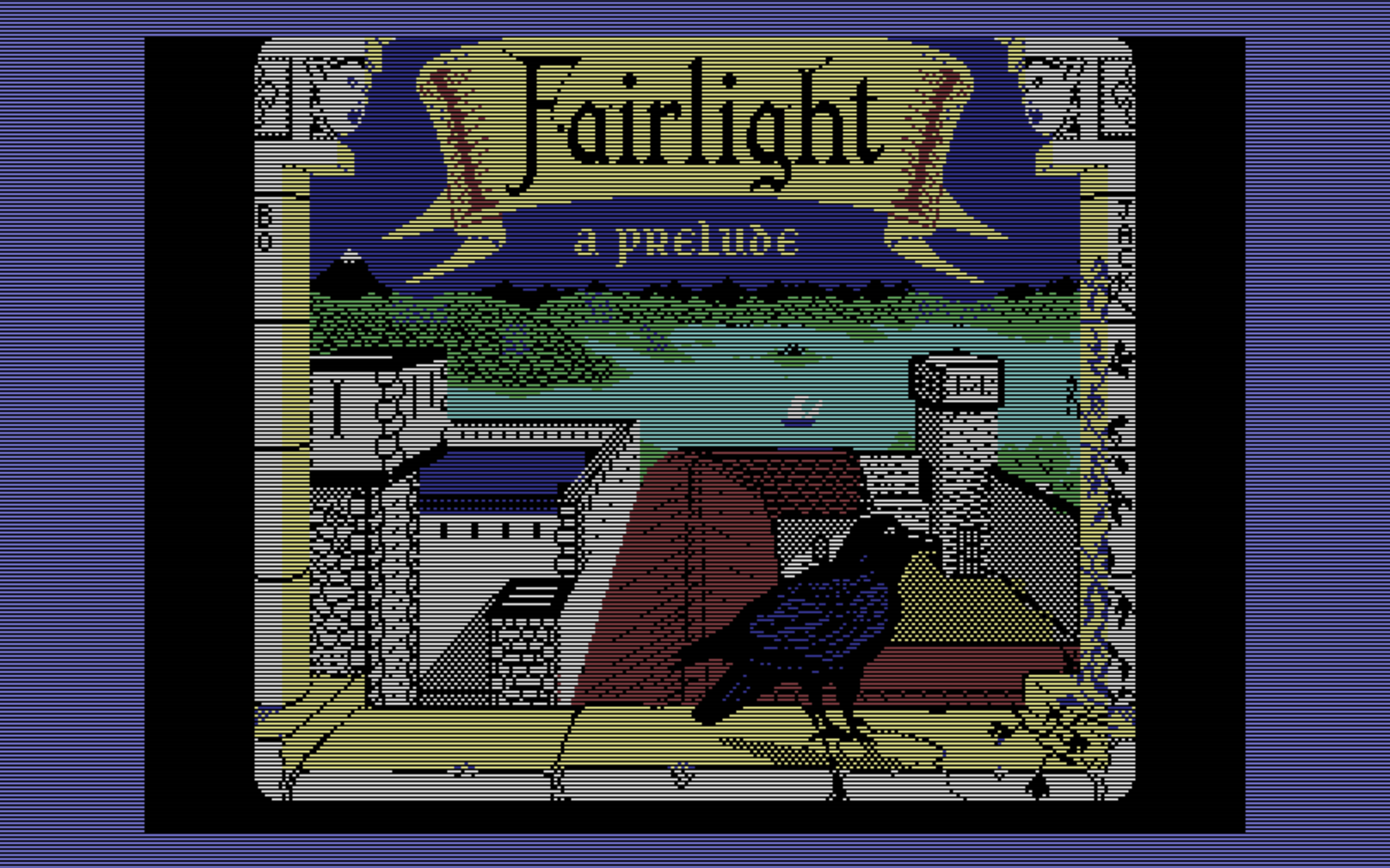
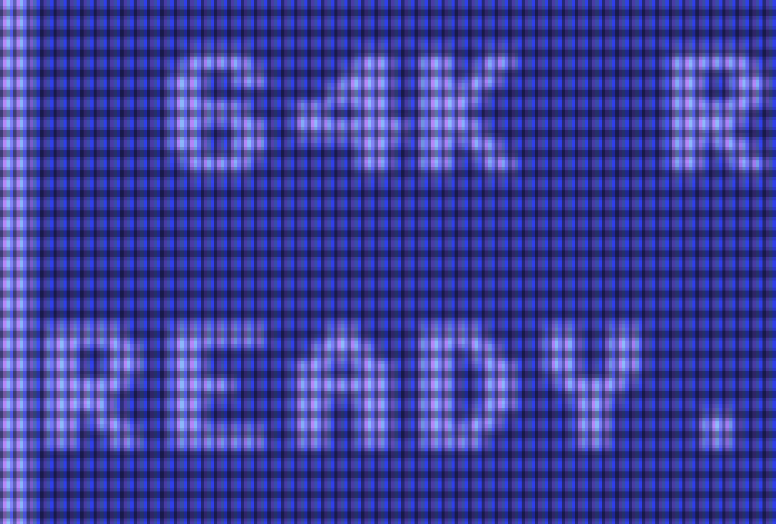
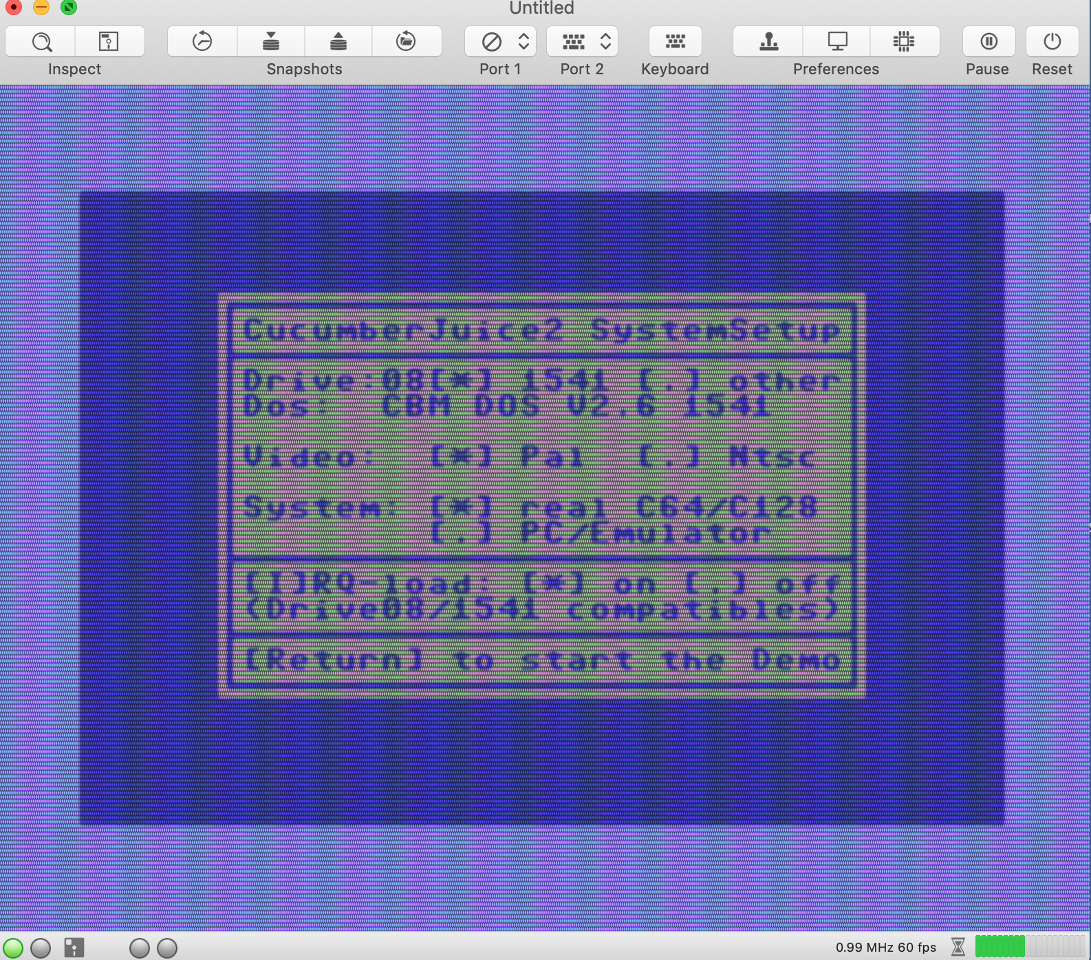
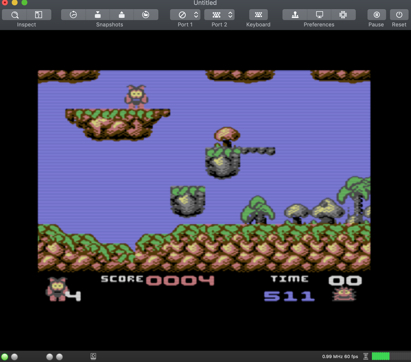
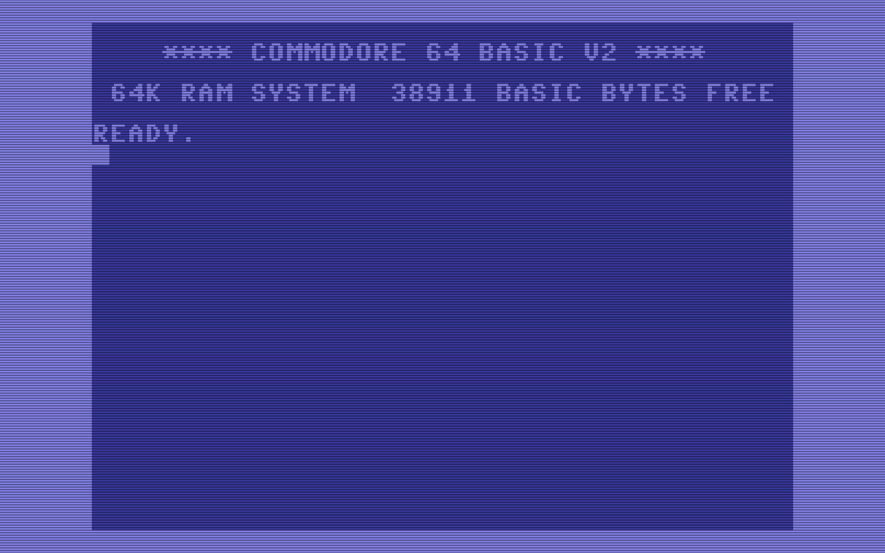
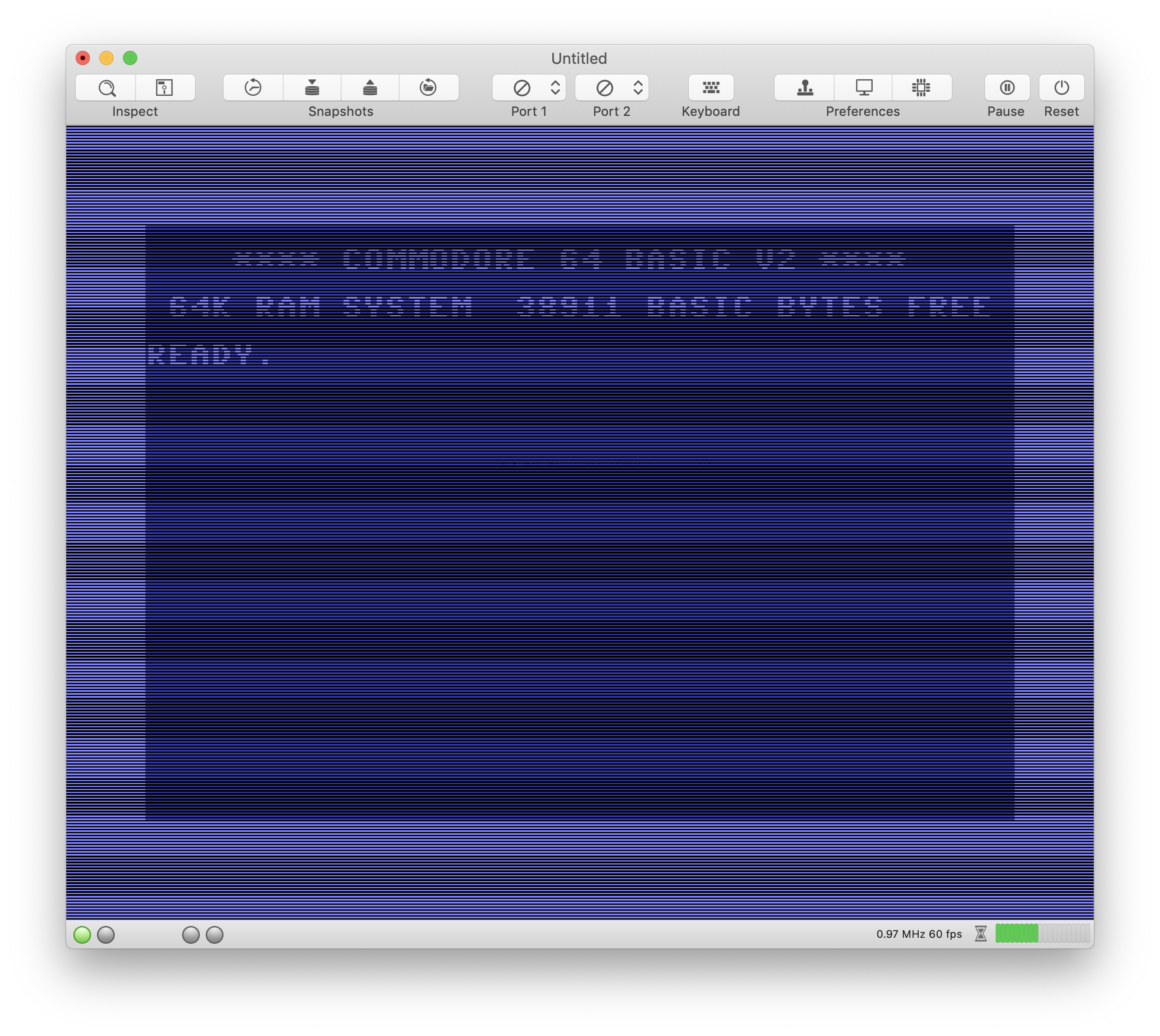
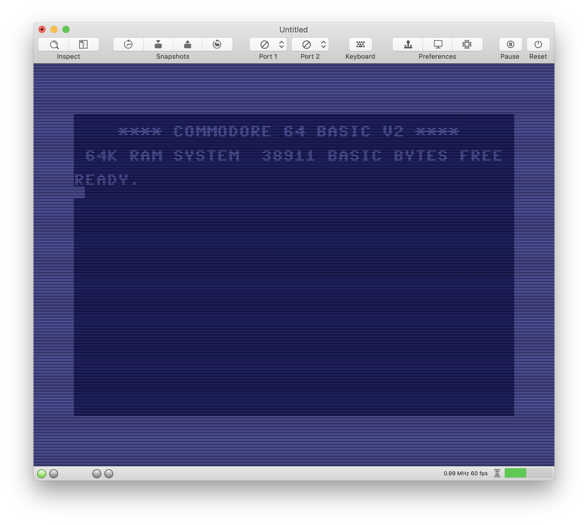
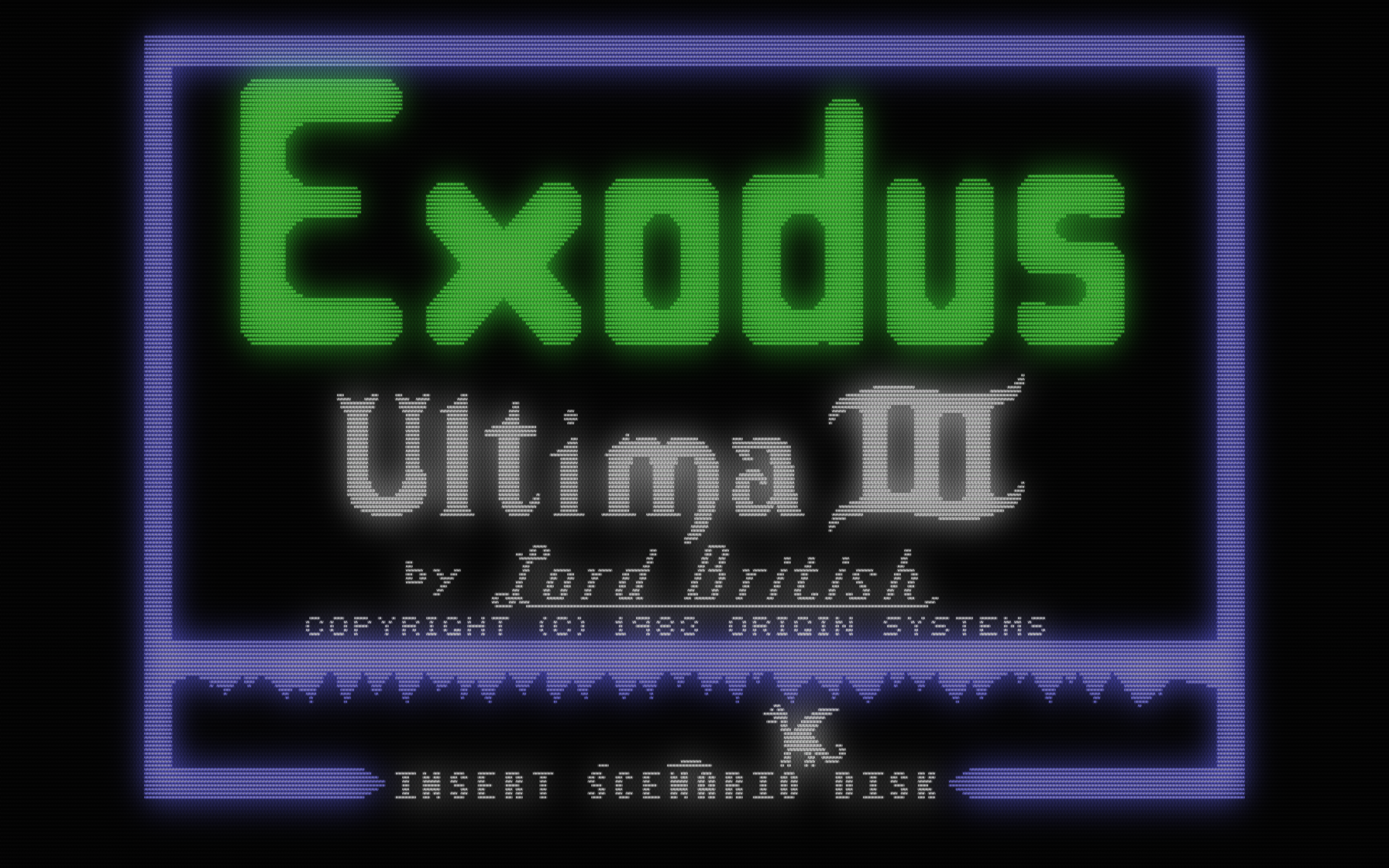
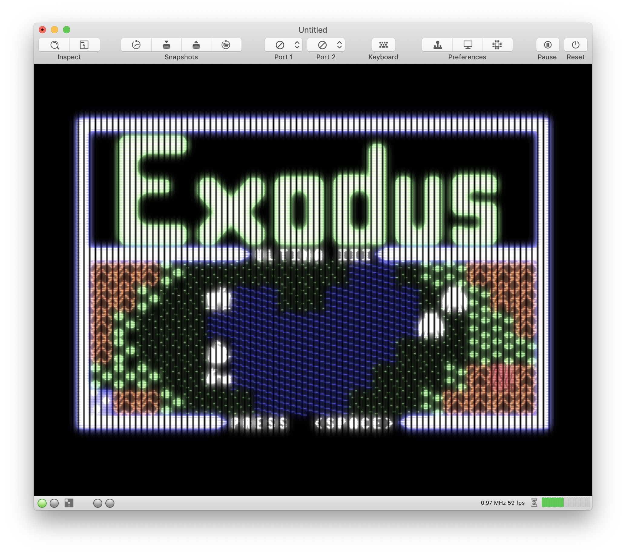
This is how the main screen looks like (4x upscaled and CRT filtered):
dirkwhoffmann
on 2 Nov 2018
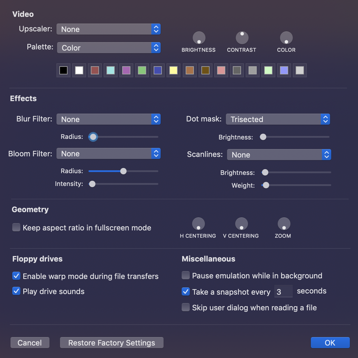
Here comes a visual prototype of the new emulator settings:
Please let me know if it looks too bloated.
dirkwhoffmann
on 2 Nov 2018
Hmm, it might be better if we just add a button "Configure ..." under the CRT option which opens up a separate window with all the controls. I guess the controls are barely used by user when decent values have been chosen.
dirkwhoffmann
on 2 Nov 2018
For me it is good the one in the image. A sub-menù could be not to easy...
Alessandro1970
on 2 Nov 2018
This is good and quick for me

 mortinus
on 2 Nov 2018
mortinus
on 2 Nov 2018
This is the best, I change often the video setting, one window ...more speed!
 UgoCaneFifone
on 2 Nov 2018
UgoCaneFifone
on 2 Nov 2018
Hi, this solution in good for me too !

Bye
 DaitarnIII
on 2 Nov 2018
DaitarnIII
on 2 Nov 2018
Hi Dirk, congrats on solving the scale/Moire issue. Also, I like the direction you are going with the controls.
Other thoughts:
Luminance issue: My preference is not to add .5 or some constant, but to leave it black and mix in the bloom to raise luminance
Do you think users will still want to blur if they are given the option to bloom? It's expensive to do on the upscaled texture, and I'm wondering if there is any value to it.
jimrogerz
on 2 Nov 2018
I've just checked in a new version into the master branch which works pretty well (I think).
That version applies the following processing chain on the GPU:
- Apply one of the upscaling compute shaders.
- Apply Apple's Gaussian High Performance Shader (with a user configurable radius).
- Apply a modified version of crt-pi inside the fragment shader.
The main reason to use Apple's gaussian shader instead of the existing one, is speed (Apple states that it's only about half the speed of copying (which is hard to believe, though)). It's so fast, because it's not a "real" Gaussian shader, i.e., it produces a result that is not mathematically 100% correct, but can hardly be distinguished from the real one by the human eye. The second reason is that it simplifies the code a lot. It's just three or four lines of code to use one of the high performance shaders.
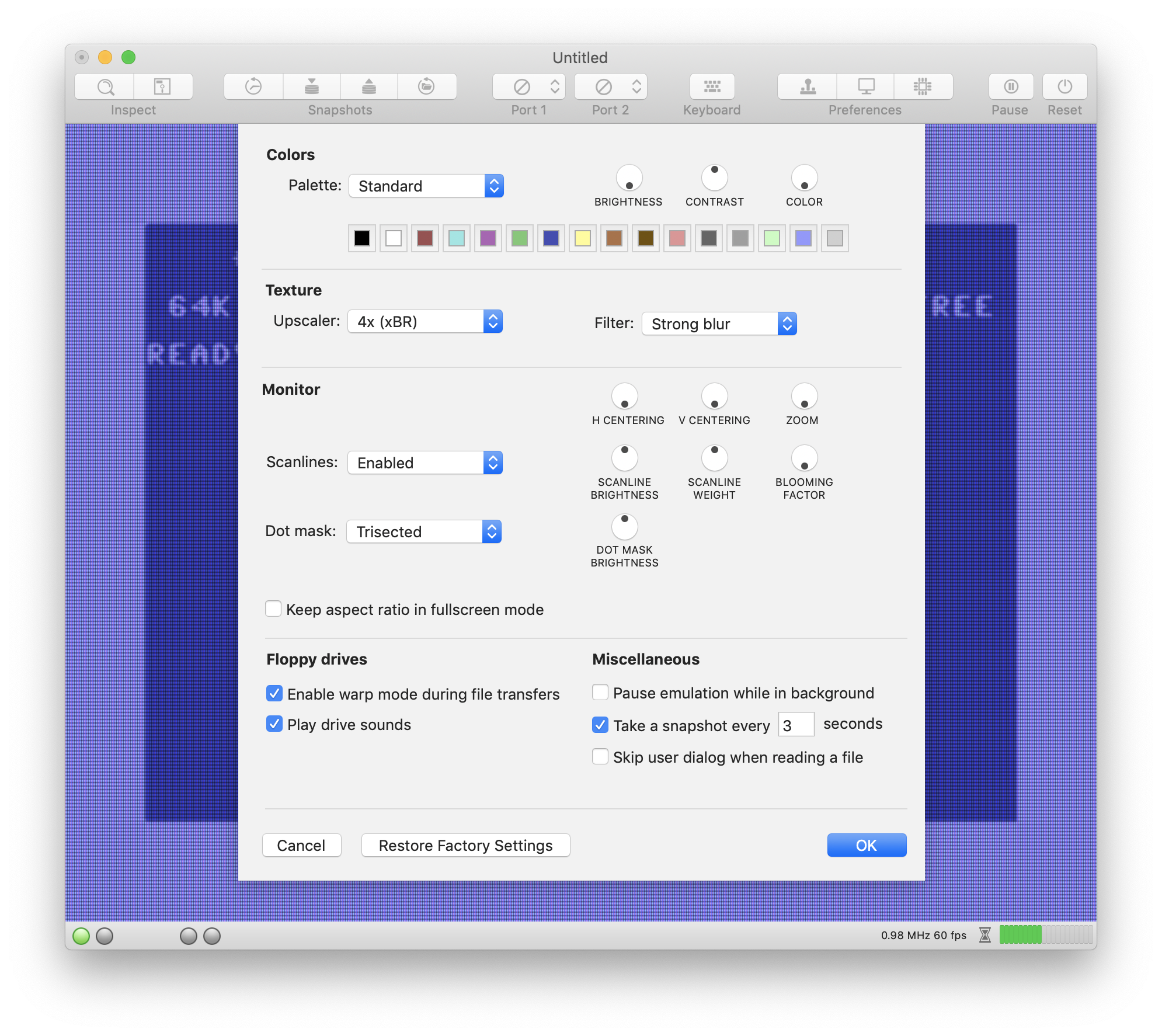
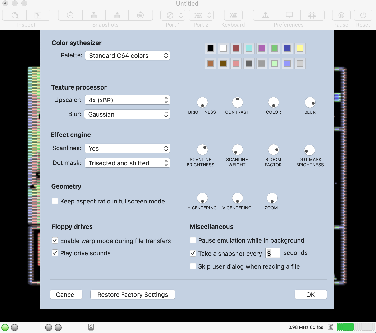
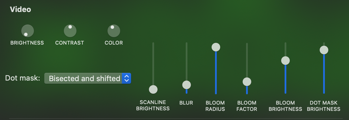
In the new emulator preferences window, you can modify almost any of the constants crt-pi is using. Now, it looks as follows:
By adjusting the various parameters, one can tweak the image quite a bit .
E.g., 4x upscaling, some blur, bisected dot mask:
4x upscaling, more blur and a trisected, shifted dot mask:
Please feel free to check it out yourself:
http://www.dirkwhoffmann.de/virtualc64/VirtualC64_crt.zip
Please report if your frame rate should drop drastically compared to version 3.0.1. On my machine, it still runs with 60fps, but it might be slower on older Macs.
dirkwhoffmann
on 3 Nov 2018
For me it works very fine!!!
It drops drastically (20/30 fps) only with gaussian (without power supply!!!) but it goes better than 3.0.1 (It is playable whitout problem). My MBP is a 2014...
Alessandro1970
on 3 Nov 2018
With power supply on my MBP 2014 has no problem:
Alessandro1970
on 4 Nov 2018
Wow, is is very fast also on my mbp 2013, gaussian and scanlines bisected as I like !
Do not use only battery !
mortinus
on 4 Nov 2018
Which game is that? 🤔 Never seen ...
dirkwhoffmann
on 4 Nov 2018
... simply sublime !!!
... beautifully fast, better than all previous versions !!!
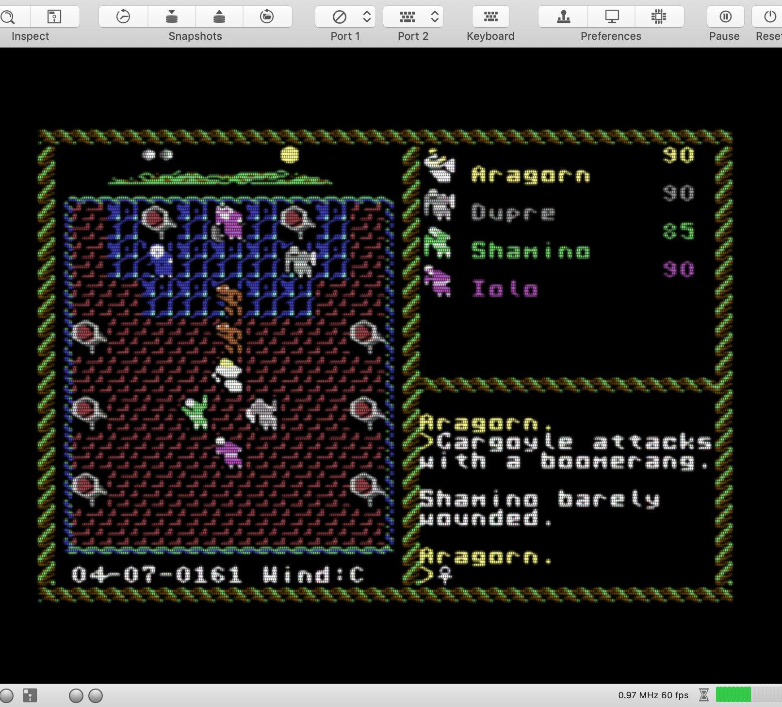
ULTIMA VI + UPSCALER 4 + BLUR gaussian + SCANLINES Dot trisected and shifted !!!!!!!
60 fps !!!
UgoCaneFifone
on 4 Nov 2018
That is the first game of the Creatures series:
creat1.zip
creat2.zip
Also these games can be played now at 60 fps!
Incredible result ...thank you !
Alessandro1970
on 4 Nov 2018
It works fine also on my MacBook Pro (Retina, 13-inch, Late 2013), 60 FPS for me too. Thanks
 rossimariolee
on 4 Nov 2018
rossimariolee
on 4 Nov 2018
VirtualC64 is very fast also on my Macbook, no problem encountered, 60 / 58 fps with gaussian mode for every game I tested.
puleyo
on 4 Nov 2018
It's quick and works fine for me too.
Thank you.
DaitarnIII
on 4 Nov 2018
This version 3.1 works very well for us too.
No speed problem on MacBook Pro 2015 with the video filters and EasyFlash cartridges we tested work properly.
Thank you.
 shauladeneb
on 5 Nov 2018
shauladeneb
on 5 Nov 2018
Version 3.1 works fine for me too, thank you.
 dada08ms
on 5 Nov 2018
dada08ms
on 5 Nov 2018
Thanks for adding all of this configuration! One issue I am having is the scale of the scanlines changing. It appears correct at the default window size (7 lines per character, 2 lines for the period):
This matches actual output:
and my experiment here: https://github.com/dirkwhoffmann/virtualc64/issues/270#issuecomment-433678397
But as I rescaled the window or went full screen, the scale changed, e.g.
jimrogerz
on 6 Nov 2018
Btw love the blur knob. You nailed it!
jimrogerz
on 6 Nov 2018
Hi Jim, you're totally right about the scanlines. I hardcoded the number of pixels between two lines in the fragment shader, so they don't scale properly 🙄. The value should be calculated dynamically based on the current screen height whenever the window changes and then passed into the fragment shader as a parameter. I'll set up a new issue for that ...
dirkwhoffmann
on 6 Nov 2018
Why not put them in after the emulator texture stage and not worry about screen height? They're always proportional, and blurring would be nice over them because a blur on a real monitor blurs the scanlines.
jimrogerz
on 6 Nov 2018
If we make the scanlines part of the texture, we're running in the Moiré effect issue. The trick is to emulate them (with an integer scaling factor) in the fragment shader where we have access to the pixel coordinate system of the Mac screen.
dirkwhoffmann
on 6 Nov 2018
Try the scanline upscaler in this build. It's pure black between scanlines, which should be worse case scenario. I think we would have the same degree of Moire if implementing the same scale scanlines in the fragment shader, but maybe I'm wrong.
jimrogerz
on 7 Nov 2018
Hi Jim. I managed to implement the scanline scaling with minimal changes to the current implementation. I have coded the distance between two scanline (in pixels) in variable 'scanline' which was already part of the fragment shader uniforms. It was used a boolean before.
http://www.dirkwhoffmann.de/virtualc64/VirtualC64_3.1.1_beta1.zip
Currently, I think the fragment shader approach has two advantages. Firstly, we can stick to the smaller texture size of 2048 x 2048. Secondly, and more important, it rules out any Moiré pattern by design. Of course, it comes for a price. Because the distance between scanlines is always forced to be an integer, there are might be a little more or little less than 8 scanlines per C64 row. However, this can only be noticed by inspecting a screenshot on a pixel by pixel basis.
dirkwhoffmann
on 7 Nov 2018
I set up a fork here to explore blooming, alternate controls, and scanlines in the upscaler: https://github.com/jimrogerz/virtualc64. I like the luminosity and sharp scanlines with the fragment shader approach, but the misalignment with emulator texture is bothering me.
jimrogerz
on 10 Nov 2018
Hi Jim. Your result looks very impressive, especially the last picture with the intense bloom effect! I think it's a good idea to have a fork for exploring this alternative way of emulating scanlines and blooming. Both approaches have advantages and disadvantages. At a later stage, we can think about offering both approaches to the user. Internally, this would mean that we have two processing pipelines (branching after the upscaling stage) which is of course doable. The more difficult point will be user experience. I think the technical details should be hidden from the user the best we can.
dirkwhoffmann
on 10 Nov 2018
It really looks like the screen is glowing. So cool 😎.
dirkwhoffmann
on 10 Nov 2018
Thanks! I also tried making fragment shader scanlines and came up with this:
    if (uniforms.scanline != 0) {
        float s = cos((512 * vert.texCoords.y) * 6.28318530718) * .5 + .5;
        color.rgb *= (1 - s * s * uniforms.scanlineBrightness);
    }
or something like
(1 - pow(s, .5 + uniforms.scanlineWeight / 5.0) * uniforms.scanlineBrightness)
to make the scanline height adjustable
jimrogerz
on 11 Nov 2018
Hi Jim. By peeking into your source code, I understood that you're performing the following processing stages (please correct me where I am wrong):
 Orig texture
 (512 x 512)
      |
      |-----------------------
      |                      |
      | Scanline upscaler    |
      v                      |
upscaledTexture              |
 (1024 x 1024)               |
      |                      |
      | Gauss                | Gauss
      v                      v
 filteredTexture       bloomTexture
  (1024 x 1024)         (512 x 512)
      |                      |
 - - - - - - - - - - - - - - - - - -  RASTERIZATION
      |                      |
      v                      v
    F R A G M E N T   S H A D E R
   (texture composition + dotmaks)
For incorporating the upscaler, one could probably extend the chain as follows:
Orig texture
 (512 x 512)
      |
      |-----------------------
      |                      |
      | 4x Upscaler.         |
      v                      |
upscaledTexture              |
 (2048 x 2048)               |
      |                      |
      | Scanline upscaler    |
      v                      |
scanlineTexture              |
 (2048 x 4096)               |
      |                      |
      | Gauss                | Gauss
      v                      v
 filteredTexture       bloomTexture
  (2048 x 4096)         (512 x 512)
      |                      |
 - - - - - - - - - - - - - - - - - -  RASTERIZATION
      |                      |
      v                      v
    F R A G M E N T   S H A D E R
   (texture composition + dotmaks)
Two open questions for me:
Do we need a 4096 x 4096 texture for the scanlineTexture? If we only double the vertical resolution (as depicted above), blurring would be stronger on the x axis (as far as I know, we cannot use different Gauss gammas for x and y).
Is it better to compute the bloomTexture out the original emulator texture (512 x 512) or the upscaled texture (1024 x 1024)?
BTW, one key aspect of your super cool looking glow effect seems to be different textures (of different sizes) which are blurred separately. Am I right?
Regarding the user experience, one could probably offer the following options:
Scanlines: None, Native, Integer scaled (I'm sure there are better names)
Behavior:
None: Disable (bypass) the scanline upscaler, disable scanline emulation in fragment shader
Native: Enable (invoke) the scanline upscaler, disable scanline emulation in fragment shader
Integer scaled: Disable the scanline upscaler, enable scanline emulation in fragment shader
dirkwhoffmann
on 11 Nov 2018
Yes that flow is correct for my fork.
- No, only 2x the vertical resolution of the original texture needed for the scanlines (512x1024). I used 1024x1024 to make the blurring even. To accommodate the other upscalers, only 2048x2048 is needed; bumping up the Y again is not necessary.
- I tested blooming on the upscaled texture (with scanlines) and it didn't look good. The blur is so heavy I don't think it matters.
Yes, having a separate texture for bloom is key because it is being blurred a lot more than the primary filtered texture.
jimrogerz
on 11 Nov 2018
I've already started to back-port Jim's shader improvements into the V3.2 branch. From a user-point of view, there will be two configuration differences compared to V3.1.
There will be three scanline filter options: "None", "(Jim)", "(Dirk)". (Jim) means that the scanlines are embedded inside the texture and (Dirk) means that they are superimposed onto the final texture after rasterization. TODO: Suitable names need to be found. Maybe, one could replace (Jim) by "Embedded" and (Dirk) by "Superimposed". Or (Jim) by "In Texture" and (Dirk) by "In Framebuffer". Any ideas are welcome.
There will be another configuration parameter "Bloom radius" which did not exist in V3.1 (because there was no separate bloom texture).
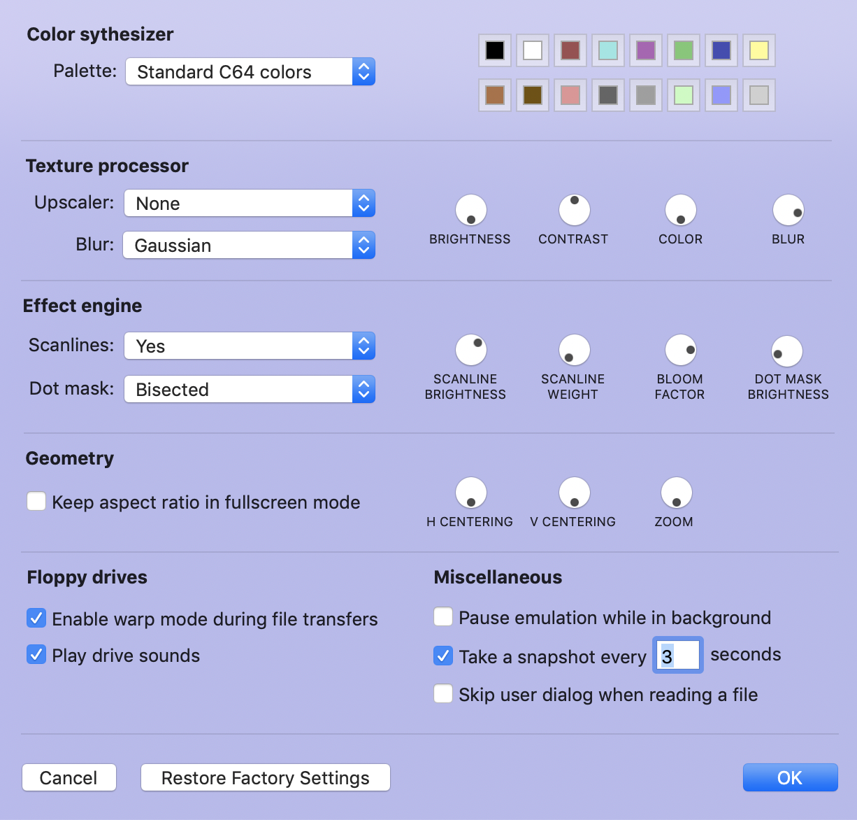
I've set up a mock-up of a cleaned emulator preferences window (not functional yet). This is how it could look like in V3.2:
dirkwhoffmann
on 12 Nov 2018
Embedded
Superimposed
they are more easy for users
mortinus
on 12 Nov 2018
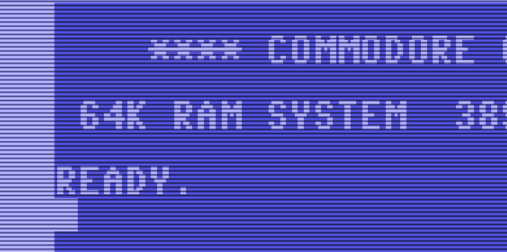
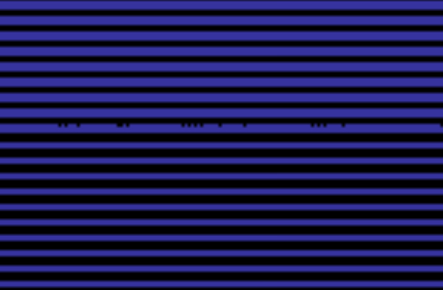
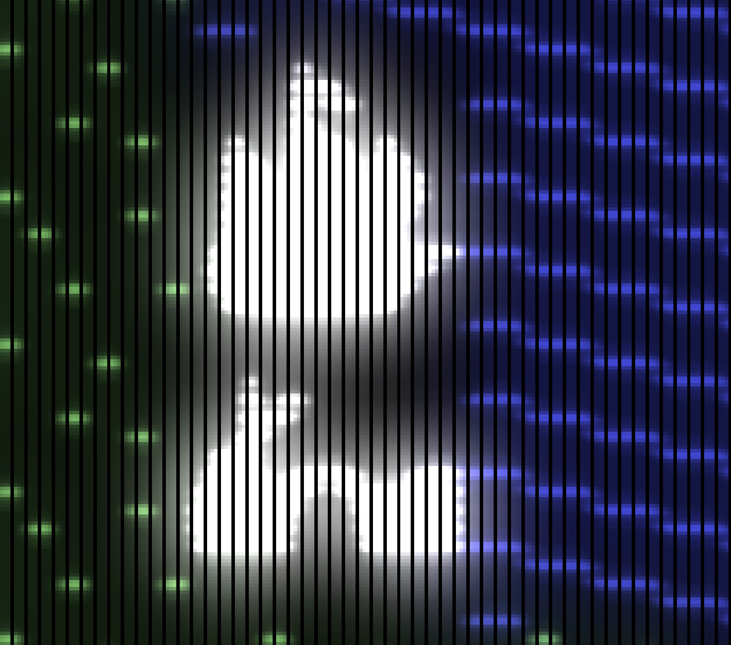
Just for fun... to demonstrate how the correct choice of the texture sampler influences the display result:
First picture: Embedded scanlines, all other retro effects off, nearest neighbor texture sampler:
Like a textbook example for demonstrating Moiré patters.
Second picture: Texture sampler replaced by a linear sampler:
Moiré patterns are still there, but much harder to notice.
dirkwhoffmann
on 12 Nov 2018
In the Embedded scanline image are these the Moire?
Alessandro1970
on 12 Nov 2018
I see a line with some black dots, strange only on that line in the middle of the screen
mortinus
on 13 Nov 2018
The dots have nothing to do with Moiré. They are either
1) due to floating point rounding errors,
2) a png compression artefact, or
3) a message from outer space.
Since 1) and 2) are unlikely, it must be 👽.
dirkwhoffmann
on 13 Nov 2018
:roll_eyes: Les Moire sont trois divinités du Destin...
mortinus
on 13 Nov 2018
https://it.wikipedia.org/wiki/Moire#/media/File:Strudwick_-_A_Golden_Thread.jpg
mortinus
on 13 Nov 2018
No, not that @mortinus
...it's something strictly related to graphics effects...
...I had a girlfriend called Moire: https://en.wikipedia.org/wiki/Milo_Moir%C3%A9
rossimariolee
on 13 Nov 2018
Hi Jim. Do you remember the parameter values you used for producing the "Ultima III with bloom" image?
BTW, I like your way for passing parameters into the compute shader:
encoder.setBytes(&crtParameters, length: MemoryLayout<CrtParameters>.stride, index: 0);
Easier and cleaner than my memcpy approach.
dirkwhoffmann
on 13 Nov 2018
I've added a bloom compute shader to the graphics pipeline which computes the bloom texture by taking the luminance of the color into account (if I remember correctly, the bloom effect mainly affects the bright colors and is very low for dark colors):
half4 color = inTexture.read(uint2(gid.x, gid.y));
float luma = (0.2126 * color.r) + (0.7152 * color.g) + (0.0722 * color.b);
color = color * luma * (3 * params.bloomWeight);
outTexture.write(half4(color.r, color.g, color.b, 0), gid);
Not sure, if multiplying with "luma" is the right way to go. This is just a start. After applying this compute shader, the bloom texture is blurred by a Gaussian filter with some radius.
Here is the result with bloom radius = 0:
And here with a radius > 0:
Code is available in the main branch.
dirkwhoffmann
on 14 Nov 2018
@Alessandro1970, looks like nearest neighbor sampling which doesn't work well with different resolution textures. @dirkwhoffmann the pipeline could be simplified by removing the smooth filter and using linear sampling in the bypass filter.
@dirkwhoffmann not sure what my values were for that Ultima III picture. I changed the brightness/contrast/color settings to emphasis the unrealistic green glow. Maybe something like this:
Which gives a picture like this using the build in my fork:
I don't think a real CRT is going to bloom that much. No idea what a realistic calculation for adjusting bloom intensity based on luminance would be. My recollection of actual CRTs is that blue is blurry as hell compared to green, so having the blue contribute ~1/10th as much as green toward the final calculation doesn't sound right. I am guessing each color should bloom proportional to it's own intensity.
We need a commodore monitor for reference!
jimrogerz
on 16 Nov 2018
After trying a couple of bloom filter variants, I am back to Jim's original approach. For the magical glow effect to work, it seems important to first blur the emulator texture and then use the pow formula which incorporates the two parameters bloomWeight and bloomBrightness. This is how Ultima III looks like with the current version on the main branch and all blooming parameters pushed to their limit:
First, I thought my monitor is going to melt in a second (😲), but fortunately, that did not happen.
I've also updated the emulator preferences. Now, there are small preview images inside the popup menu items for selecting the color palette and the dot mask. If you modify a color parameter, the preview images update on-the-fly (😎).
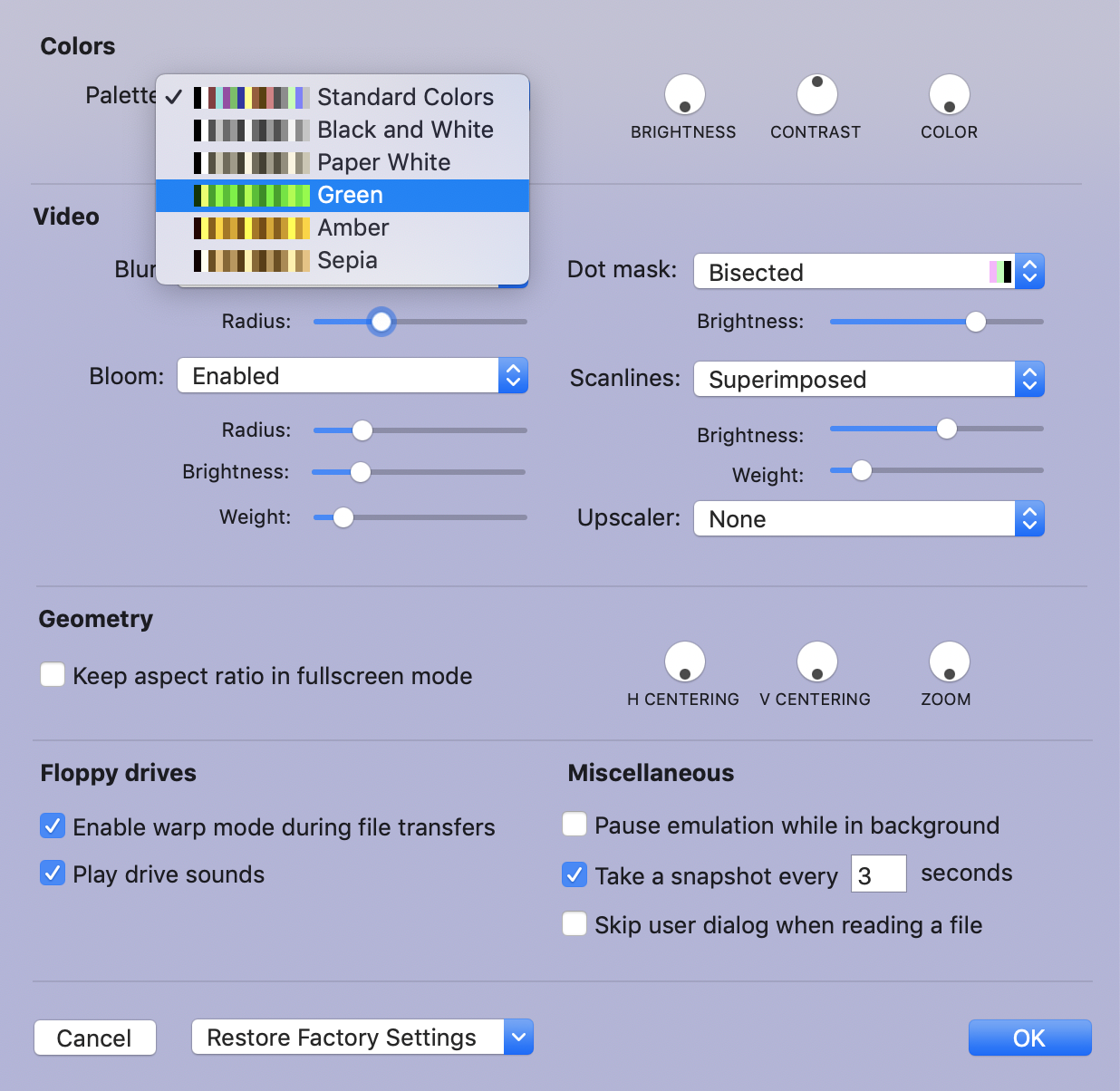
BTW, do we really need "Paper White" and "Black and White". It looks pretty much the same.
The shader code has changed considerably, too. I simplified the parameter passing to the compute shaders and the dot mask is now provided as a texture (which is faster and more flexible). New dot masks can be added easily.
I agree with Jim that we need a Commodore monitor for reference. Maybe also an old low-quality TV to get a real retro feeling. I remember that my first TV was so 🤭 that I was hardly able to read the characters. At that time, I was quite jealous of my cousin, who had a real Commodore (1802?) monitor with a really sharp picture.
dirkwhoffmann
on 17 Nov 2018
Yes, I could prefear the B/W option.
Alessandro1970
on 17 Nov 2018
Looking good Dirk! The vertical stripes look a little off though.
I'm working on getting a Commodore monitor. Check out this screen shot of a 1702:

The glow around MARS goes pretty far.
jimrogerz
on 17 Nov 2018
Yesterday, I looked at the Mars picture for a longer time and, as always, it gets interesting when looking into details. I tried to do some back engineering of what I see and came across some oddities I don't understand.
Let's get started. First, I wanted to know what the picture is telling me about the dot mask of the Commodore 1702, so I measured out a single character:
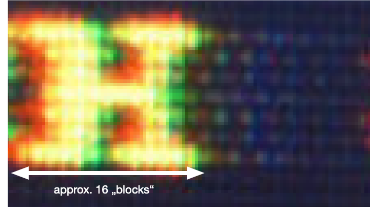
There are about 20 characters on the screen (is "Mars" perhaps a VC20 game?) and a small web search revealed that the Commodore 1701 has a dot pitch of 0,64 mm. I assumed the same dot pitch for the 1702. Therefore, I concluded that we have a dot mask that looks as follows:

If this is correct, a single character would span about 1 cm on the real display which sounds reasonable to me.
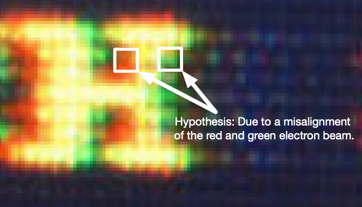
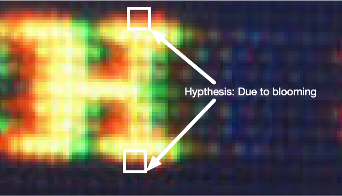
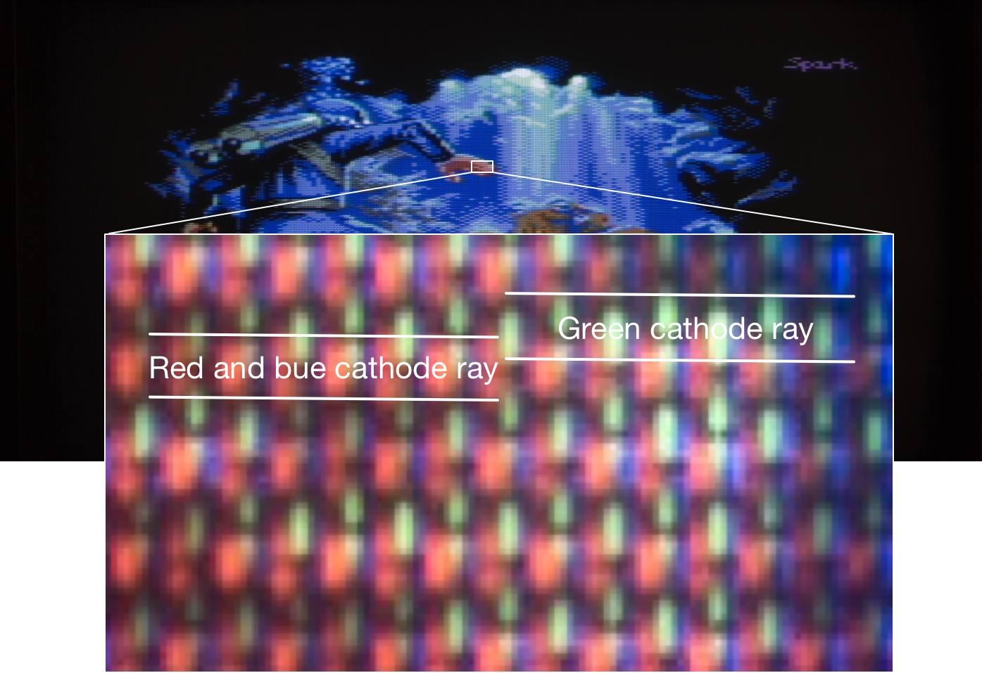
Now, I looked closely at the character 'H'. Red overhangs on the left and green on the right. I guess this effect has nothing to do with blooming. I think it's likely that this effect is caused by a small misalignment of the cathode ray tubes. The following picture backs this hypothesis (I think):
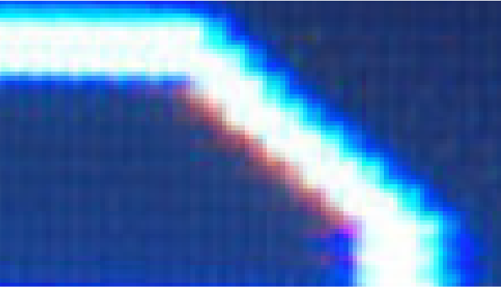
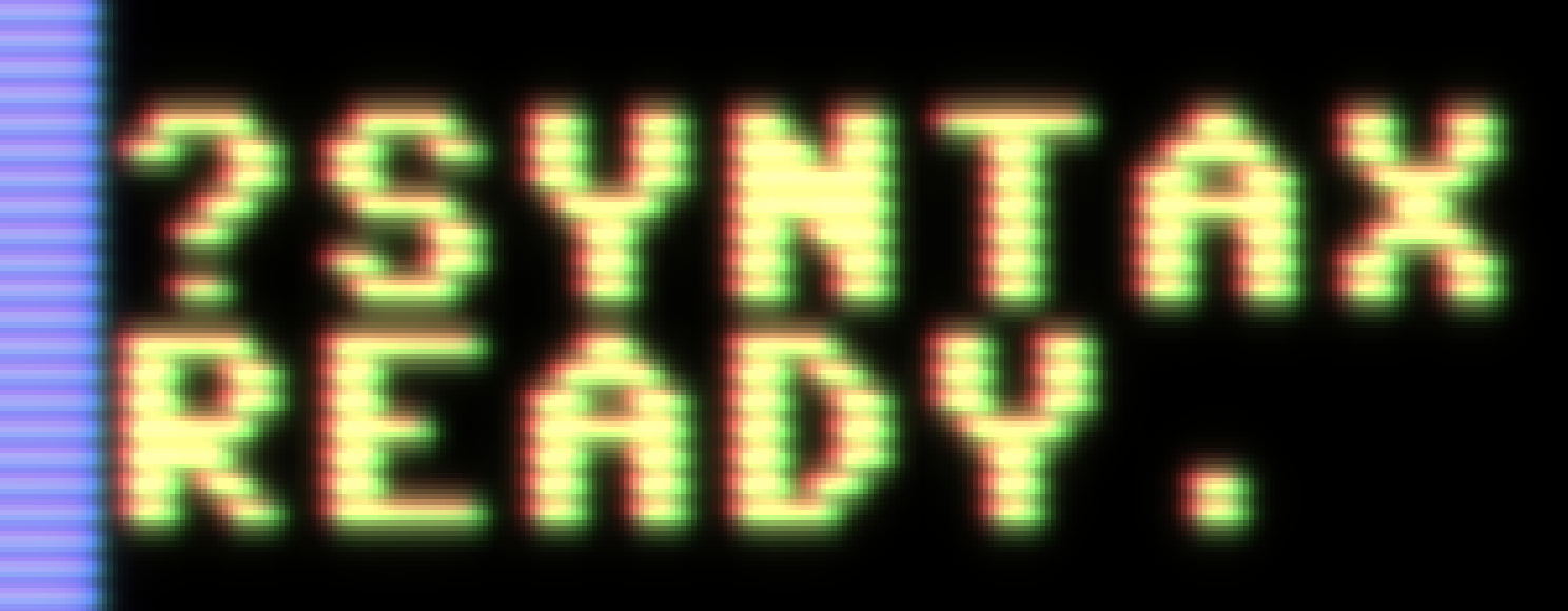
If this is true, we can easily emulate this effect in VirtualC64 by reading the R, G, B values separately from the texture with a small offset for each color. This is a screenshot from an experimental build of VirtualC64:
Now, let's look at the upper and lower side of the character 'H' in the original screenshot again. We see that red overhangs in both directions. In my hypothesis, this effect is due to blooming and not due to misalignment. But if this is correct, red would bloom more than green (?!). Other effects are thinkable as well. Maybe, the cathode rays are not focused exactly the same and red simply strays more than green. Don't know. Perhaps we could emulate this by splitting the emulator texture in sub channels and blur them separately with a different radius.
But there is one thing in the screenshot, I really don't understand. Look at this:
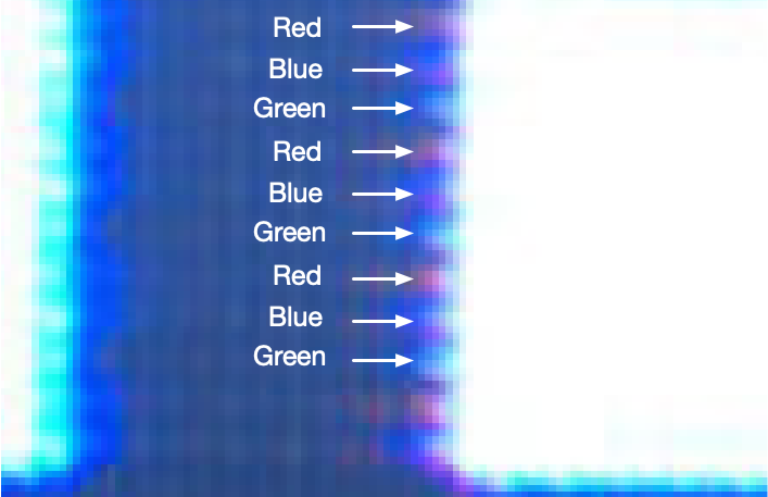
There are consecutive lines with an overhang of a repeating pattern of R,G,B. How is this possible physically? Alien messages (although it's a Mars game) can be ruled out I guess, because aliens always send prime numbers and I didn't came across a single prime number during my investigations.
dirkwhoffmann
on 18 Nov 2018
Appendix to my post:
dirkwhoffmann
on 18 Nov 2018
Love this thread, such a hard core CRT discussion! The photo of the 1702 is invaluable, I can do some photos of my 1084s this week. I can create a test image with all the primary colours and some patterns.
Intereseting to see the misalignment in the 1702 photos, not sure if my monitor looks that way. Have to say some misalignment would be great to have as an option. Maybe there should be an "age"/"price" slider to make the screen progressively worse, hehe!
There were some shots above with very hard raster lines and dot masks. For bloom to look good, I think its important its not 100% filtered by the dot mask. The brightest parts of the glow should blend the pixels together, so maybe the glow should be added in the end? In my shader-hack, I added a small 1 pixel blur at the start of the shader operations, and then a very large 10 pixel glow at the very end.
But there is one thing in the screenshot, I really don't understand. Look at this:
There are consecutive lines with an overhang of a repeating pattern of R,G,B. How is this possible physically?
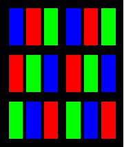
I would assume this is due to the dot mask or rgb of the pixels being shifted half a pixel for every other line? All online samples show this shift happening vertically, not horizontally though, which is strange. Seem to remember it being the other way around, like the first image in this post: http://filthypants.blogspot.com/2013/02/designing-large-scale-phosphor.html
(A great blog for CRT references, by the way)
superrune
on 19 Nov 2018
Hi Superrune, thank you very much for your comments! I've already read (portions) of the blog you mentioned, and yes, it's very interesting. I agree that we need to rework the current dot mask emulation. The sharp black lines are definitely not correct and I guess we need to apply the dot mask effect before applying the bloom filter.
Regarding the 1702, you are saying that the dot mask looks as follows, right?
dirkwhoffmann
on 19 Nov 2018
Yes, it might be like that for the 1702, seems like the simplest solution at least. I wish I had a 1702 to look at, it was the monitor I owned as a teenager in the 80s :)
I have a 1084s now, and the pattern is a bit different. I've shot some high resolution stills of it tonight in case you want to examine further. It looks to me like it has some horisontal bleed in the red channel.
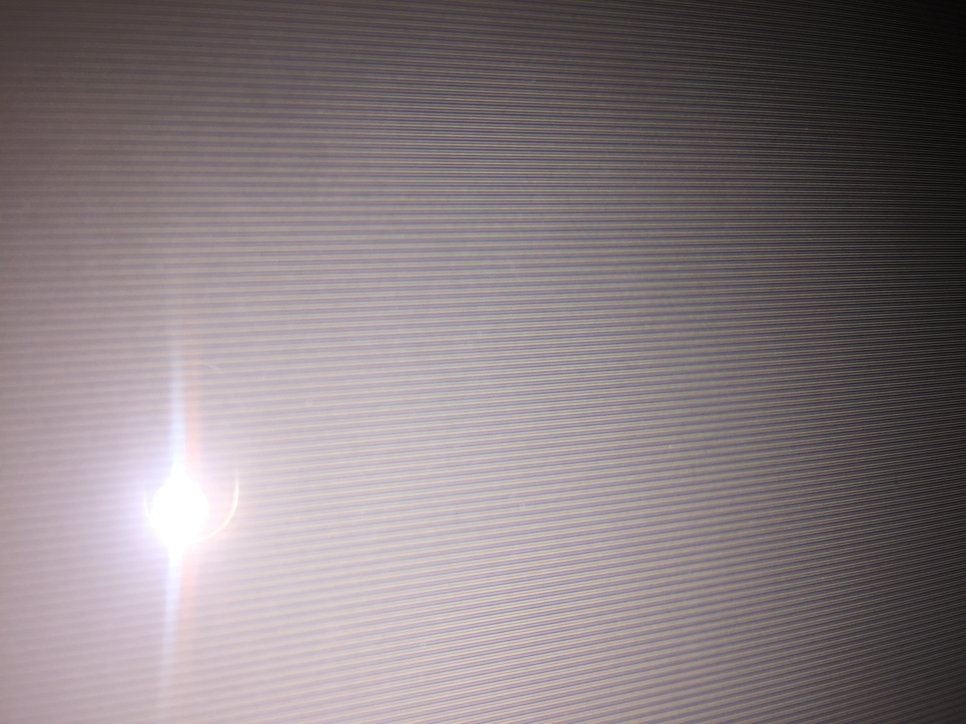
Here's the entire screen with a test image I made. The white boxes in each corner is 2x2 characters in size. The small boxes inside each colour square is 1x1 character:

Save it out view it in an image viewer to see the details.
Here are some closer shots:
http://www.superrune.com/offsite/2018/1084s_photo_02.jpg
http://www.superrune.com/offsite/2018/1084s_photo_03.jpg
http://www.superrune.com/offsite/2018/1084s_photo_04.jpg
I handheld the camera, so they are a bit blurry. I can set up a tripod and do some more shots if you are interested.
And one of my own images for a sample of some actual artwork :)
http://www.superrune.com/offsite/2018/1084s_photo_05.jpg
superrune
on 20 Nov 2018
@dirkwhoffmann, you are correct the RGB separation has nothing to do with blooming. There are rings on the neck of the tube you turn to try to align the colors as best you can. Nice job simulating it!
I picked up a 1702 today (the same one used for the screenshots I posted earlier). Unfortunately I do not have the right cable to hook it up yet, but once I do I'll start posting pictures and attempting to clone whatever I see.
jimrogerz
on 21 Nov 2018
Here's a close up of the 1702 screen, turned off:
It's more focused near the bottom of the picture. Looks like a trinitron pattern.
jimrogerz
on 21 Nov 2018
Definitely a Trinitron pattern on the 1702.
dirkwhoffmann
on 22 Nov 2018
The 1804 pictures are great. I think the slight blurriness is not a problem. When the images are enlarged, the dot mask can be recognized easily. Whereas the 1702 uses a Trinitron pattern, the 1804 uses a slot mask.
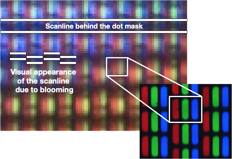
The shifted arrangement of the slot mask elements has an interesting effect on the scaliness. Although the scanlines are straight horizontal lines behind the dot mask, they appear shifted to the viewer.
dirkwhoffmann
on 22 Nov 2018
Also interesting. There seems to be a vertical misalignment between the cathode rays:
dirkwhoffmann
on 23 Nov 2018
I see the the misalignment. I think you're seeing the same issue that you simulated with the offsets. There's an electron gun for each color and often misaligned.
No progress on my end. Got a 1702 cable, but having disk drive issues, so I can't see much other than the initial screen.
jimrogerz
on 2 Dec 2018
What about loading Ultima III from datasette 🤔? OK, just kidding, would likely take until after Christmas.
dirkwhoffmann
on 2 Dec 2018
In the most recent alpha, I've applied some modifications to the CRT emulation:
http://www.dirkwhoffmann.de/virtualc64/VirtualC64_3.3_alpha10.zip
- The two sliders for disaligning the cathode rays are now active (BTW, is it "disalignment" or "misalignment" or "displacement" 🤔).
- Turning on dot mask emulation doesn't affect the luminance any more.
- Before computing the bloom texture, the three color channels are split and processed separately. This allows us to blur each channel with a different radius. It has an undesired side effect though. If the blur radius of a certain color is much larger compared to the others, the maximum intensity of that color is considerably lower in many areas, causing a color shift. Maybe it makes sense to unify the blur radius and the bloom intensity in one single parameter.
dirkwhoffmann
on 2 Jan 2019
I came across a nice article about CRT emulation by Kyle Pittman:
http://www.gamasutra.com/blogs/KylePittman/20150420/241442/CRT_Simulation_in_Super_Win_the_Game.php
Kyle is using an interesting approach for emulating distortion. He renders the texture on a 3D mesh:
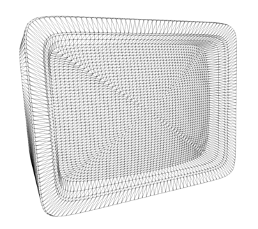
It'll be cool to have some dynamic mesh computation with adjustable curvature (just dreaming 😴).
BTW, distortion is an effective weapon against Moiré patterns.
dirkwhoffmann
on 2 Jan 2019
I played around with the latest version, and the amount of controls you get are amazing! Great work on the CRT options, you can really create the look you want now! I am going to spend some time trying to match up my 1084s with the settings. Maybe it would be handy to have a couple of presets for users to try out?
BTW, I notice my Virtual C64 is really heavy on the CPU now, is that because of the CRT shader?
superrune
on 14 Jan 2019
BTW, I notice my Virtual C64 is really heavy on the CPU now, is that because of the CRT shader?
Hmm, that's not really good news 🙁. If three-channel blooming is applied, there is more GPU stuff to do (RGB splitting takes place and three separate bloom textures are computed). If one-channel blooming is applied, there shouldn't be a big difference in CPU and GPU usage between V3.2 and V3.3.
Does the CPU load decrease if you disable all CRT related options?
dirkwhoffmann
on 14 Jan 2019
Shaders does not make a huge difference. I am running this on a Macbook Pro Retina late 2013, which should be a pretty decent machine.
No GPU shaders: 40% load
W/GPU shaders: 50% load
When accessing disk: 120% load (!)
I might have been confusing this with VICE, but I dont seem to remember VirtualC64 being so heavy on the CPU before? I see VICE stays at arount 15%, peaking a 40% when accessing disk.
superrune
on 14 Jan 2019
Good news is: Performance didn't decrease compared to previous versions.
As my personal benchmark for comparison, I usually run a freshly booted C64 in warp mode. V3.3 runs at over 8 MHz on my machine which is pretty good compared to older versions (some versions prior to the enhanced drive emulation run faster though).

When running at the original C64 speed, CPU load on my machine is about 30%:

Yes, VICE is faster, but I have no idea why. They don't do any heavy graphics stuff, but the graphics post-processing shouldn't affect the CPU that much anyway. It puts a heavy load on the GPU though.
BTW, could you check if the frame rate is still 60Hz on your machine if all CRT options are enabled? If it's lower, we might need to optimize the graphics pipeline somehow.
Regarding the 120% load when accessing the disk: Do you have "Enable warp mode during file transfers" enabled? That would explain the full CPU load (VICE doesn't have this feature 😝).
dirkwhoffmann
on 14 Jan 2019
Thanks - did not know about the warp setting! That fixed the peaking.
I have not seen it drop below 60Hz on my machine, even with every effect is on. So everything is good on my "old" Macbook :)
superrune
on 15 Jan 2019
Related issues
 Somuchfun
·
3Comments
dirkwhoffmann
·
5Comments
Alessandro1970
·
3Comments
Alessandro1970
·
5Comments
puleyo
·
6Comments
Somuchfun
·
3Comments
dirkwhoffmann
·
5Comments
Alessandro1970
·
3Comments
Alessandro1970
·
5Comments
puleyo
·
6Comments
Most helpful comment
Wow, is is very fast also on my mbp 2013, gaussian and scanlines bisected as I like !

Do not use only battery !