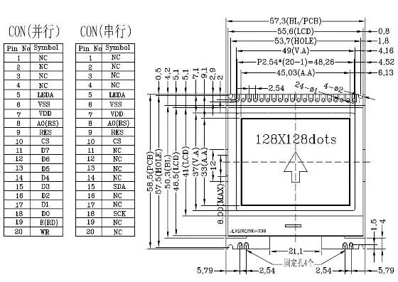
Looking for some help connecting this COG (Chip on Glass) 128 x 128 Display
I have 4-wire SPI version
Would love to get this up and running but seems i can't figure out the naming convention of pins if i use the LiquidCrystal library.
Any insight would be appreciated
 32teeth
All 30 comments
I will try to reactivate the code. Hope this device will work for you: #164
 olikraus
on 8 Apr 2020
olikraus
on 8 Apr 2020
Constructor should be U8X8_UC1617_JLX128128_4W_SW_SPI as an example (all other constructors are also available)
Maybe you can test this and send me some pics (if there is something visible)
You can download the latest U8g2 beta release from here: https://github.com/olikraus/U8g2_Arduino/archive/master.zip
- Remove the existing U8g2_Arduino library (https://stackoverflow.com/questions/16752806/how-do-i-remove-a-library-from-the-arduino-environment)
- Install the U8g2_Arduino Zip file via Arduino IDE, add zip library menu (https://www.arduino.cc/en/Guide/Libraries).
olikraus
on 8 Apr 2020
Hello
I use the library too but XBM sample code is working but the picture I created in my bitmap is not visible.I wonder why it may be the problem
 tunaftlmk
on 9 Apr 2020
tunaftlmk
on 9 Apr 2020
Will test and report back
Thank you
32teeth
on 9 Apr 2020
@tunaftlmk Moved your question to #1152
olikraus
on 9 Apr 2020
@olikraus
Do you have an sample code for this?
Am i meant to create U8X8_UC1617_JLX128128_4W_SW_SPI or does it exist?
32teeth
on 9 Apr 2020
It should exist in the beta release. You can use any u8x8 example and add the constructor there.
olikraus
on 9 Apr 2020
This is what i have
By the resistors in place, you can tell it's Serial as per the designation on the side silk

32teeth
on 9 Apr 2020
yes, looks like SPI. Example code could be this (see also the u8x8 examples in the Arduino IDE).
The pins need to be defined according to your wiring.
//U8X8_UC1617_JLX128128_2ND_4W_SW_SPI u8x8(/* clock=*/ 13, /* data=*/ 11, /* cs=*/ 10, /* dc=*/ 9, /* reset=*/ 8);
U8X8_UC1617_JLX128128_2ND_4W_HW_SPI u8x8(/* cs=*/ 6, /* dc=*/ 4, /* reset=*/ 12);
void setup(void)
{
  u8x8.begin();
  u8x8.setPowerSave(0);
}

void loop(void)
{
  u8x8.setFont(u8x8_font_chroma48medium8_r);
  u8x8.drawString(0,0,"Hello World!");
  delay(2000);
}
The "dc" pin in U8g2 refers to A0(RS) pin on your display.
D0 is clock and D3 is data. CS and reset should be clear.
olikraus
on 9 Apr 2020
Deleted and answered here: https://github.com/olikraus/u8g2/issues/1152
olikraus
on 10 Apr 2020
Something is still wonky
It may be me, but... ...here is my connection, i still get blank screen?
| Display | Arduino | Function |
|-----|-----|-----|
| D0 | 13 |clock|
| D3 | 11|data|
| D6 | GND||
| D7 | 3.3||
| CS | 10|cs|
| RST | 8|reset|
| RS | 9|dc|
Software SPI version
# 4W software spi
U8X8_UC1617_JLX128128_4W_SW_SPI u8x8(/* clock=*/ 13, /* data=*/ 11, /* cs=*/ 10, /* dc=*/ 9, /* reset=*/ 8);
Hardware SPI version
# 4W hardware spi
U8X8_UC1617_JLX128128_2ND_4W_HW_SPI u8x8(/* cs=*/ 10, /* dc=*/ 9, /* reset=*/ 8);
Common Code
void setup(void)
{
  u8x8.begin();
  u8x8.setPowerSave(0);
}

void loop(void)
{
  u8x8.setFont(u8x8_font_chroma48medium8_r);
  u8x8.drawString(0,0,"Hello World!");
  delay(2000);
}
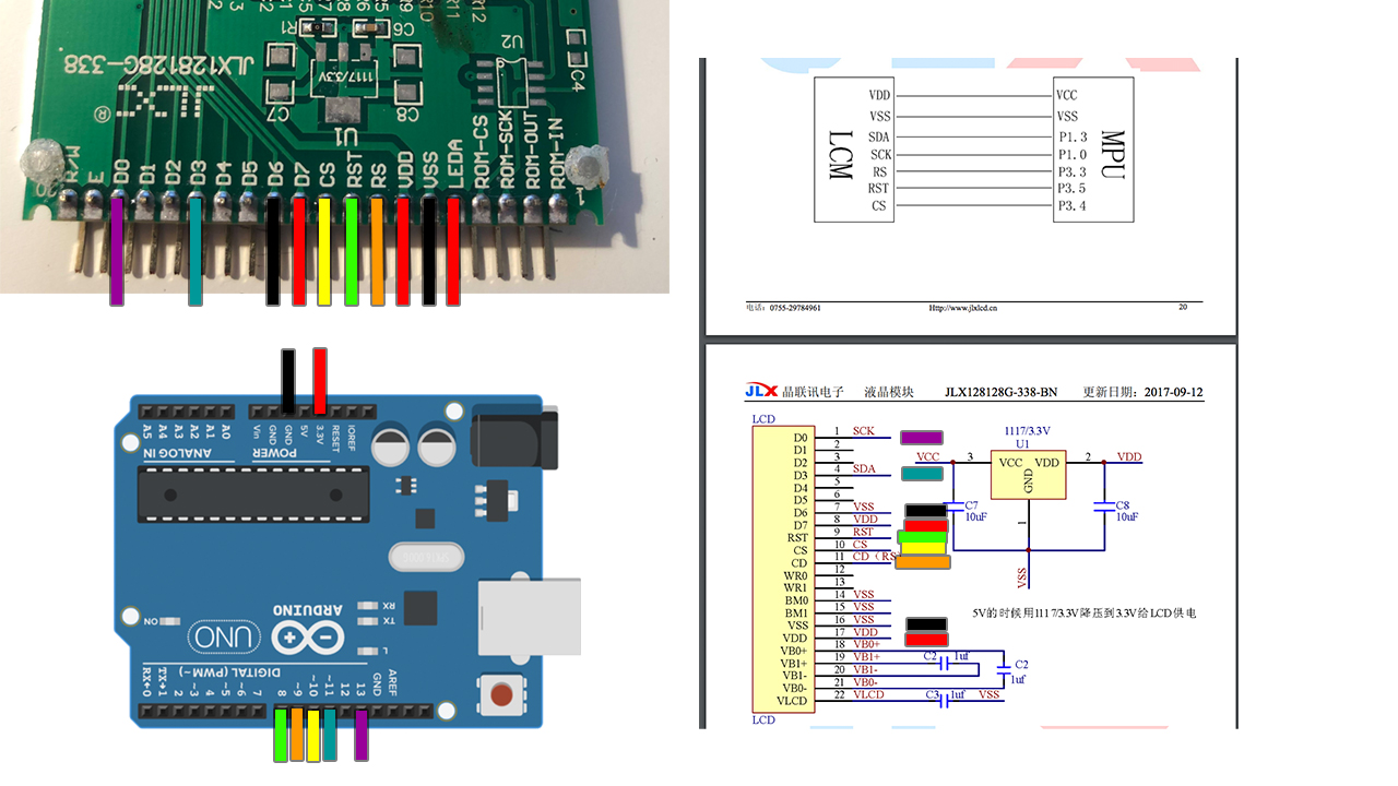
Both of the above produce blank screen
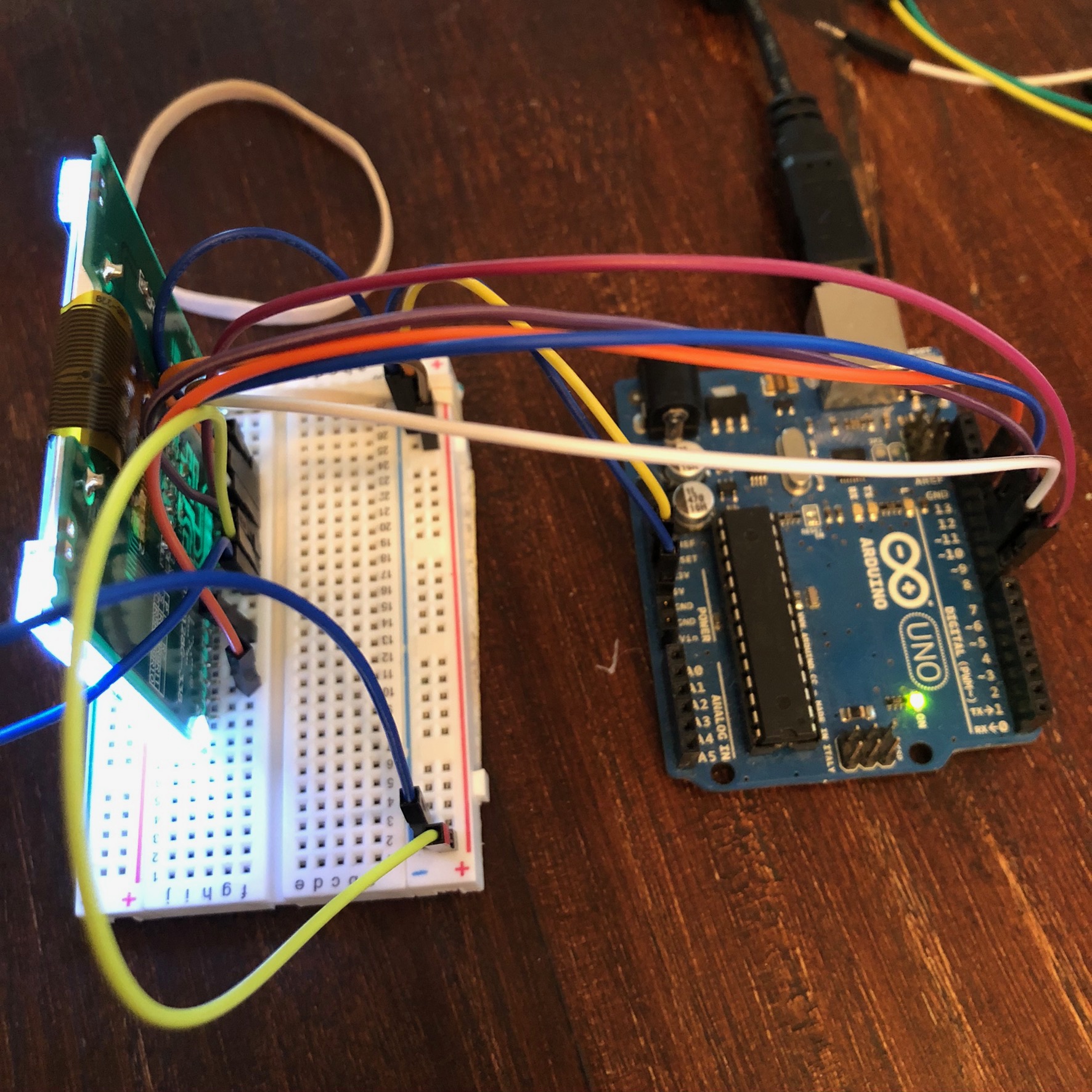
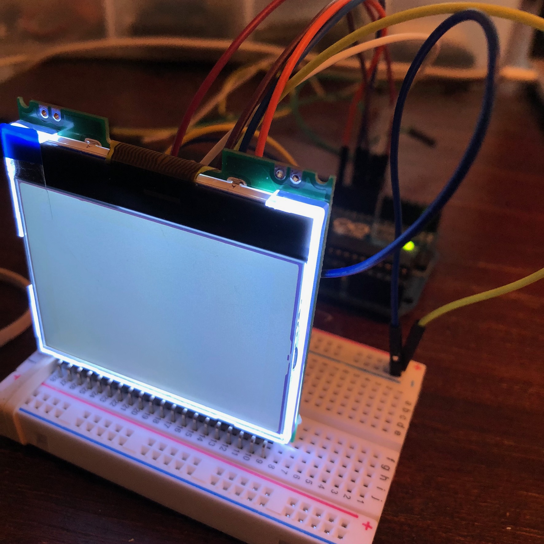
What am i missing???
32teeth
on 14 Apr 2020
One issue could be the missing level shifter. Gpio output of the Arduino is 5v, but the display only accepts 3.3v. no sure, whether this will work.
Additionally: the u8g2 code for this display was never confirmed. So, I don't know whether this is a software problem.
olikraus
on 15 Apr 2020
Does the 8x8 code work?
32teeth
on 15 Apr 2020
u8g2 is build on top of u8x8. So the answer is: I do not know, but if u8x8 works, then also u8g2 will work. Indeed if the SW does not work, then the u8x8 needs to be fixed. But the problem is: We do not know exactly whether it's a HW or SW problem.
This is my current summary:
Your hardware might not work, because of two reasons:
- There is no level shifter between the 5V Arduino and the 3.3V display (the display might be destroyed already)
- Your hardware is assembled on a solderless breadboard. Such a protoboard is very unrelibale and my cause wiring problems, which are very hard to detect.
On the other side the software never got tested. I think I have a similar display in my lab, and as far as I remember I also was not able to activate it. Whether I had a SW problem or HW problem is also unknown. Due to missing time, I gave up working on the display in 2017.
Here is my plan: I will try to find the display in my lab. I will do another attempt to make it work.
What I can not tell is any timeline on this. Although lock down, I still have to do a lot of different other things... so u8g2 (as a spare time project) has to wait...
olikraus
on 15 Apr 2020
Ok, found the displays in my lab...
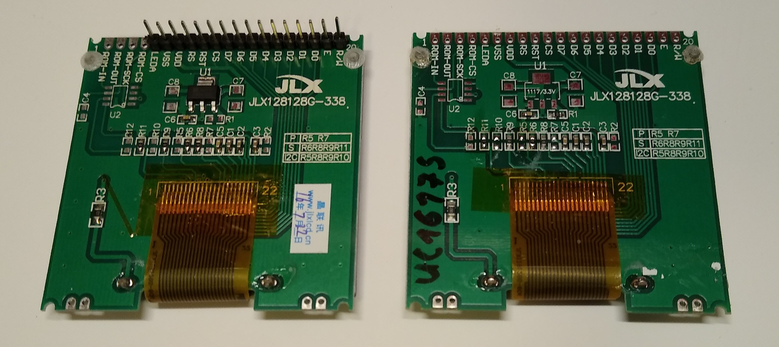
olikraus
on 18 Apr 2020
I made some progress, but whatever code was there is very much incomplete :-(
olikraus
on 18 Apr 2020
Good news: Software should work now.
Constructor prefix: U8X8_UC1617_JLX128128 (same as above)
I have created u8g2 release 2.28.4
You can download the latest U8g2 beta release from here: https://github.com/olikraus/U8g2_Arduino/archive/master.zip
- Remove the existing U8g2_Arduino library (https://stackoverflow.com/questions/16752806/how-do-i-remove-a-library-from-the-arduino-environment)
- Install the U8g2_Arduino Zip file via Arduino IDE, add zip library menu (https://www.arduino.cc/en/Guide/Libraries).
olikraus
on 19 Apr 2020
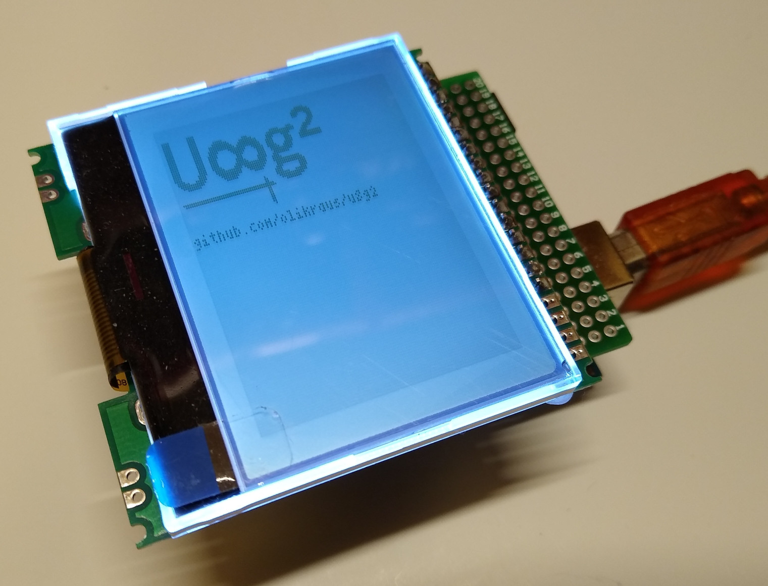
The natural orientation is rotated by 90 degree. So use U8G2_R1 or U8G2_R3 if required.
olikraus
on 19 Apr 2020
thank you, i will be back soon
olikraus notifications@github.com, 19 Nis 2020 Paz, 10:41 tarihinde şunu
yazdı:
[image:
https://raw.githubusercontent.com/wiki/olikraus/u8g2/img/uc1617_jlx128128.jpg]
https://raw.githubusercontent.com/wiki/olikraus/u8g2/img/uc1617_jlx128128.jpgThe natural orientation is rotated by 90 degree. So use U8G2_R1 or U8G2_R3
if required.—
You are receiving this because you were mentioned.
Reply to this email directly, view it on GitHub
https://github.com/olikraus/u8g2/issues/1151#issuecomment-616067892, or
unsubscribe
https://github.com/notifications/unsubscribe-auth/AKCQP4DE6ZWDBDY7UXVXSGTRNKTKNANCNFSM4MD7O3WA
.
tunaftlmk
on 19 Apr 2020
Amazing work @olikraus
any chance you can share your wiring?
32teeth
on 19 Apr 2020
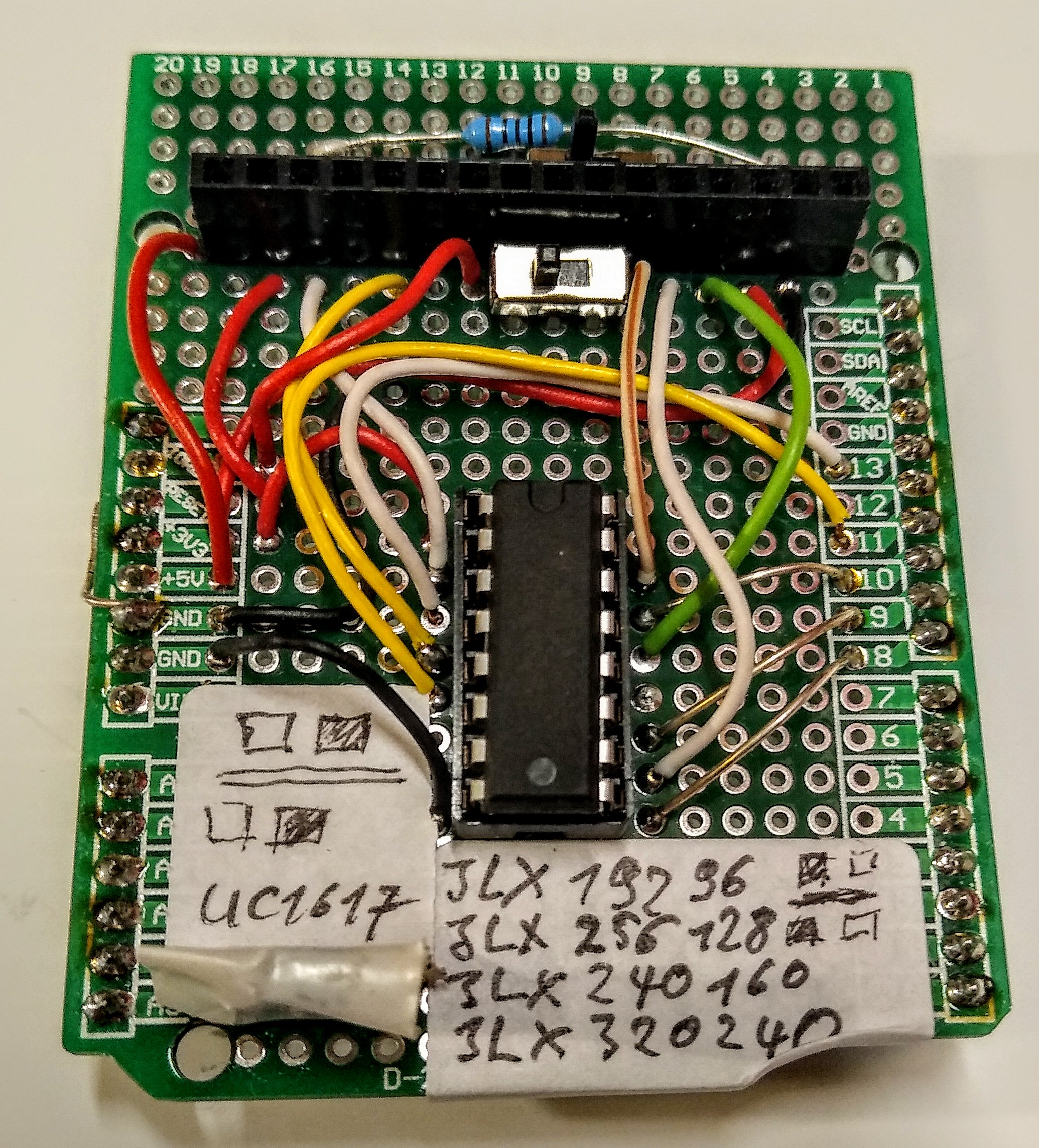
All five signals (clk, data, cs, dc and reset) are routed via an 74HC4050 (the IC in the middle).
The pinout is the same for all the JLX display, so I reused my old protoboard here. The only difference is, that D5..D7 must not be connected (this is different for other JLX displays). Because of this, I have added two switches.
olikraus
on 19 Apr 2020
Thank you
Seems that the one thing i am missing is the 74HC4050 level shifter
From the image it just seems you are using them straight forward (judging from color)
32teeth
on 19 Apr 2020
Yes, Arduino outputs are inputs of the 4050. Output of the 4050 go to the display.
olikraus
on 20 Apr 2020
Okay, awesome.
I have gotten it to work, only need to set rotation
OOC, is there a U8g2 version as well as u8x8
32teeth
on 21 Apr 2020
Yes, all constructor calls are there. Not sure whether I updated the wiki.
olikraus
on 21 Apr 2020
Yes, all constructor calls are there. Not sure whether I updated the wiki.
This should also work on Adafruit Feather Huzzah _(ESP32 4MB)_
The U8g2 compiles to big for standard _328_ or _32u4_
32teeth
on 21 Apr 2020
This should also work on Adafruit Feather Huzzah (ESP32 4MB)
If this is a question, then: Yes
The U8g2 compiles to big for standard 328 or 32u4
It depends. Using the F constructor often breaks those small controller with a large display. I mean, your display has 128x128 pixel. This would require a 2k buffer with the F constructor. But a 328 only has 2K Ram, so it will not work. On the other side the 1 constructor and u8x8 should still work.
olikraus
on 21 Apr 2020
Got it going on a 4MB ESP32
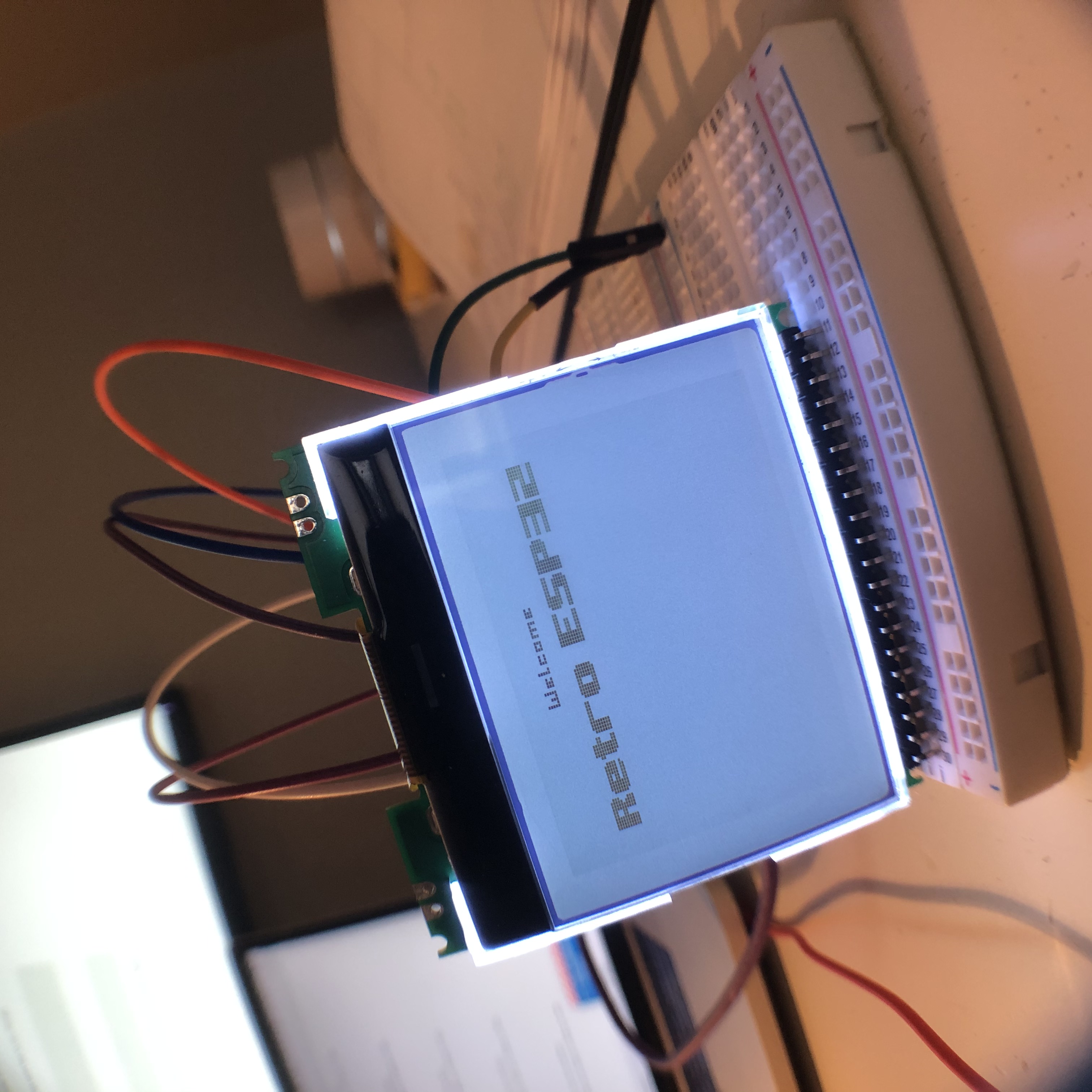
Thank you very much for your help!
My next joy will be to convert gnuboy to use this display... ...hopefully
You can close #1151 if you wish
32teeth
on 22 Apr 2020
Nice, thanks for sharing the picture.
olikraus
on 25 Apr 2020
Related issues
 sarwarislammoon
·
4Comments
sarwarislammoon
·
4Comments
 idreamsi
·
7Comments
idreamsi
·
7Comments
 Audio-Rochey
·
4Comments
Audio-Rochey
·
4Comments
 WaRZaT
·
3Comments
WaRZaT
·
3Comments
 BrickBee
·
3Comments
BrickBee
·
3Comments