Hi. I've used this library successfully for many of my projects with different displays. But now I've bought a b/w round display from aliexpress. I was confused by the fact that it has double resolution than the other ST7920 displays, but I decided to take the risk and buy some for experiments.
So either it is a completely different IC, because now I've noticed that it is written as IST7920, (and I even found manufacturer's site without any datasheets), or I am doing something wrong.
I have blank screen with any code and any config I have tried. I asked seller about datasheet or demo code, but still waiting for a reply.
Meanwhile maybe someone have any ideas how I can make nay progress with this?
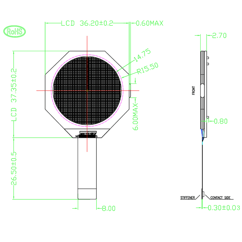
Schematics for the display, from the product page
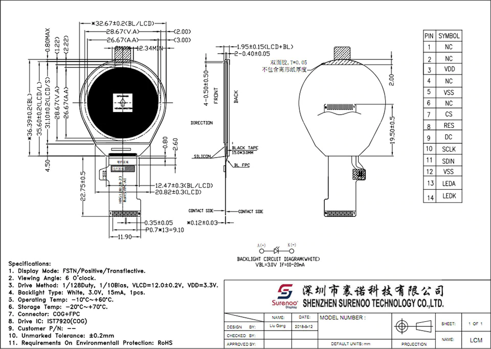
Notice that it has a DC pin, that other ST7920 displays don't. I've tried connecting it both to VCC and Ground, as well as leaving it floating, with no effect.
The product page have video of this display showing images, so I guess it CAN work.
 monte-monte
All 42 comments
Hmm... yes, I think it is a different type of driver from Integrated Solutions Technology.
Too bad that the driver name is very similar to ST7920, but indeed ST7920 and IST7920 are probably two different controller.
I also didn't found a datasheet for the IST7920...
 olikraus
on 20 Sep 2019
olikraus
on 20 Sep 2019
@olikraus so yesterday I've contacted every seller or manufacturer I could find who claim those display are their own product. And finally I've just received a full datasheet for IST7920. I've uploaded it to google drive: https://drive.google.com/file/d/1_Wua6_c8BRstTdBi0KkmJyZKHEFPrZRw/view?usp=sharing
I am also waiting for some demo code from a seller I've bought this displays from.
I would appreciate if you could look into this datasheet and say if it's any different from original ST7920.
monte-monte
on 20 Sep 2019
I've already noticed the timings are different. And I wonder what are the corresponding pins in the datasheet naming and the ones in a drawing. My guess is A0 - DC, CS1B - RS, CS2 - CS, what do you think?
monte-monte
on 20 Sep 2019
Yes A0 is DC. Probably CS1V = CS and CS2 is not used (tied to high). RES is reset.
The controller has a complete different command set. So obviously none of the existing drivers will work. I can offer to create the framework here, but fine tuning probably needs to come from your side...
olikraus
on 20 Sep 2019
That's will be great! I was ready to try my best adapting your code for this IC, but honestly, I don't have enough experience to do this effectively. But I will do any testing and tuning on my end, of course.
I am working on a project which includes this displays. Now I have 3 of them, but probably will buy more if they show them good. I can send you one or two for your experiments later, if you're interested.
monte-monte
on 20 Sep 2019
sounds good... I hope it will be sufficient to see some pictures of the display from time to time.
olikraus
on 20 Sep 2019
... ok, have to interrupt here... will continue tomorrow...
olikraus
on 20 Sep 2019
I had a closer look to the datasheet. Some values like LCD Bias and Duty are mentioned in the above screenshot, other settings are fully unknown (lFrequency select and power on mode).
Getting a demo code for your display or a more detailed startup sequence with the config values for your display would be very helpful.
More specific, unknown values are:
Datasheet Page 24, value for "Power Control"
Datasheet Page 25, value for "Voltage Generator Clock Frequency select"
Datasheet Page 28, value for "Reference Voltage Select"
olikraus
on 21 Sep 2019
I had same questions yesterday, while reading the datasheet. Today I've received a sample code from another manufacturer. They produce slightly different displays, but it seem they are the same at base level. Here it is
I think I can try to use this settings and see if it works.
monte-monte
on 21 Sep 2019
Nice... however: The BIAS command 0x30 expects a 6 bit value as argument, but the example has:
            SdCmd(0x30);        //Bias
            SdCmd(0xE0);        //08 8a f8
This means, the value can not be correct (or the datasheet is wrong). Anyhow, according to the above datasheet the value for the BIAS should be 1/10 which is 16 (decimal).
olikraus
on 21 Sep 2019
Maybe I missed something, but there is no 0xec command:
            SdCmd(0xec);        //0xfd *2
            delayms(10);
and the 0x32 has a wrong comment (it is temp. compensation)
olikraus
on 21 Sep 2019
Crap. I didn't look closely into code before I uploaded it. It seems to be code for completely different screen. Duty cycle is wrong too. Though the characteristics of the display on their schematic are the same as the one I have.
I guess this guy have sent me random file he has by his hand...I will ask him again. The one who sold me mine displays said to wait 5 days, because he is "traveling".
monte-monte
on 21 Sep 2019
Well, at least partly the setup got confirmed. But yes, still some doubts are there :-p
The datasheet specified the minimum SPI cycle with 260ns. This is 3.8 MHz. I will set the default to 3MHz. Maybe you can try 4MHz later.
olikraus
on 21 Sep 2019
As for missing settings. "Power Control" has basically 4 variants, so I guess I just can try them one by one and see which one works.
"Reference voltage select" as I understand decides which voltage will be supplied to the panel. This panel needs 12V.
 (Page 28)
Do you understand what A and B variable stands for? Anyway, datasheet sayc IC can provide maximum 13.5V so the register value has to somewhere near the biggest side. I think I can try C8. I guess i will see if the contrast is ok and understand how far away from correct value I am))
monte-monte
on 21 Sep 2019
Actually I've just calculated 215(D7). Am I right?
That's not a fraction, that's just silly notation...
monte-monte
on 21 Sep 2019
I assume A and B just denote the first and second part of the sum.
In my current setup PVC_ADJ will be off (value 0). I think this will simplify the reverse engineering ;-)
RR(a) is still my biggest concern. I will use RR(a) as contrast value, so you can set the RR(a) value via the setContrast() u8g2 command. Because we have no idea about the value here, this will probably the first thing to test.
If setContrast(0) will show no pixel and setContrast(255) will make all pixel visible, then at least we know that the applied voltage is sufficient.
olikraus
on 21 Sep 2019
Actually I've just calculated 215(D7). Am I right?
Well... I guess this does not really matter, as we do not know the exact voltage required for the display.
That's not a fraction, that's just silly notation...
:+1:
olikraus
on 21 Sep 2019
Yes, PVC_ADJ needs to be 0, it seems to be only for adjusting and then burning fuses.
And I calculated actual RR(a) to be D7 if we believe the display schematics, where they say it is 12V supply to LCD.
as we do not know the exact voltage required for the display.
We do:)
But setting contrast by command seems to be neat :)
monte-monte
on 21 Sep 2019
I have checked in the code so far... I will create a beta release later...
olikraus
on 21 Sep 2019
Constructors:
U8G2_IST7920_128X128_1_4W_HW_SPI(const u8g2_cb_t *rotation, uint8_t cs, uint8_t dc, uint8_t reset = U8X8_PIN_NONE)

U8X8_IST7920_128X128_4W_SW_SPI(uint8_t clock, uint8_t data, uint8_t cs, uint8_t dc, uint8_t reset = U8X8_PIN_NONE)
u8x8 hello world compiles with
U8X8_IST7920_128X128_4W_SW_SPI u8x8(/* clock=*/ 13, /* data=*/ 11, /* cs=*/ 10, /* dc=*/ 9, /* reset=*/ 8);
olikraus
on 21 Sep 2019
ok... I have created beta 2.27.1...
Maybe you can see that happens with your display with this constructor.
My suggestion is to start with the u8x8 hello world example first. Use the U8X8 constructor from above...
You can download the latest U8g2 beta release from here: https://github.com/olikraus/U8g2_Arduino/archive/master.zip
- Remove the existing U8g2_Arduino library (https://stackoverflow.com/questions/16752806/how-do-i-remove-a-library-from-the-arduino-environment)
- Install the U8g2_Arduino Zip file via Arduino IDE, add zip library menu (https://www.arduino.cc/en/Guide/Libraries).
olikraus
on 21 Sep 2019
I just realized an issue. It looks like this display requires an external 12V voltage. This means, we have to remove all the setup for the internal charge pump voltage generation...
olikraus
on 21 Sep 2019
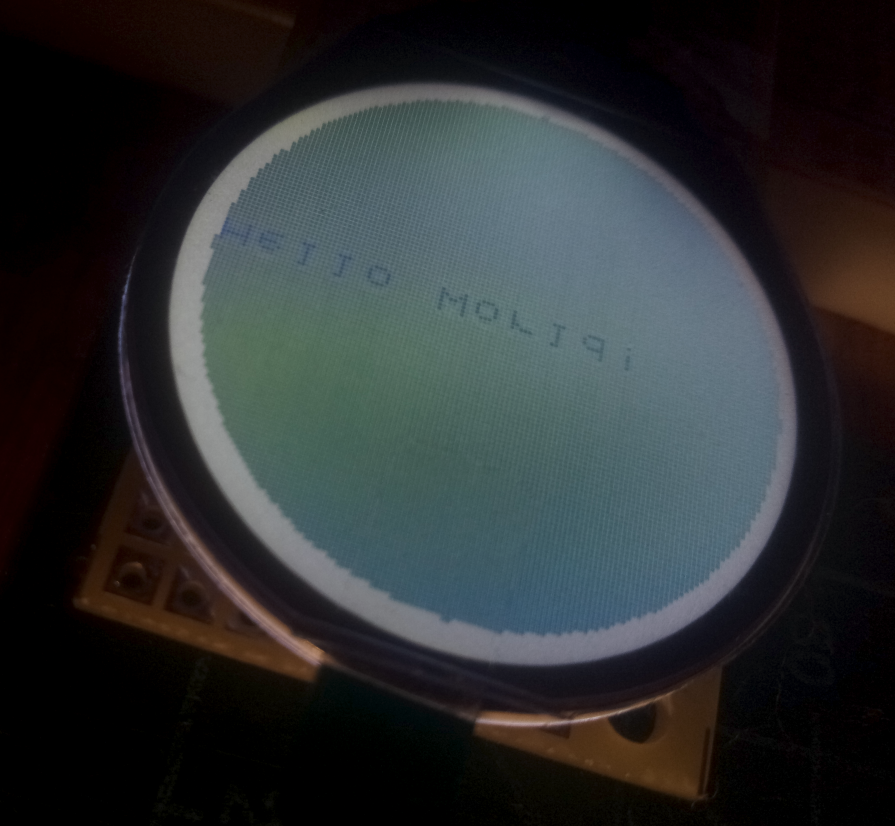
YAY! It's alive. Kinda:)
So it prints "Hello world" but mirrored, and after a second it fills an screen with 50%gray. Actually it seems to oscillate between text and black fill, because I still see text and it slightly flickers.
monte-monte
on 21 Sep 2019
I just realized an issue. It looks like this display requires an external 12V voltage. This means, we have to remove all the setup for the internal charge pump voltage generation...
But there is no dedicated LCD voltage pin.
monte-monte
on 21 Sep 2019
Wow, I am impressed. Looks already great. Congratulation so far.
But there is no dedicated LCD voltage pin.
ah, ok, then the setup seems to be ok (more or less). Are there any caps visible on the flex cable?
So it prints "Hello world" but mirrored
Not a big issue, just change the 0x060 command. it could be 0x064 or 0x068... Let me know the correct value, so that I can add this to the code.
oscillate between text and black fill
hm... is your power supply reliable? Maybe also add some extra caps to the power supply (near the flex cable).
Also change the contrast value. Maybe also the setup needs to be adjusted somehow...
olikraus
on 21 Sep 2019
it could be 0x064
This works.
Are there any caps visible on the flex cable?
Yes there 10 caps on a ribbon cable.
I get power from my laptop, tried powerbank no changes. But it doesn't seems to be power related.
Let me explain. I power MCU - screen is completely blank, after 2 seconds text appears without any background, half a second later appears this fill that covers whole display and it seems to flicker. So something happens after sending data to the display.
monte-monte
on 21 Sep 2019
Contrast that is. Setting contrast to 100 makes it work:
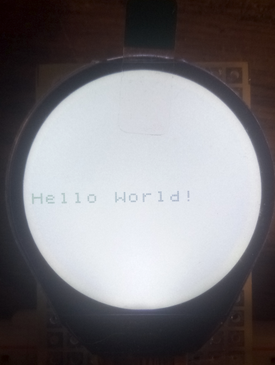
Suitable range 90 - 110. But text appears somewhat faint. Like 50% intensity. Cant tell if it is the display itself or our settings.
monte-monte
on 21 Sep 2019
Also tried graphic test with u8g2 class, it draws a row 7 pixels high in the middle of the display, everything beyond isn't shown.
monte-monte
on 21 Sep 2019
and it seems to flicker.
I still think you need a 1uF between VDD and VSS next to the connector of your display.
Like 50% intensity. Cant tell if it is the display itself or our settings.
Let's adjust the setup a little bit:
Booster
For the booster try 0x0fe and 0x0ff. Probably you need to adjust the contrast.
https://github.com/olikraus/u8g2/blob/master/csrc/u8x8_d_ist7920.c#L116
Voltage
https://github.com/olikraus/u8g2/blob/master/csrc/u8x8_d_ist7920.c#L110
The value 0x3f is from the pastebin code. Maybe try the suggested values 0x031 or 0x011 from the datasheet (or even total other values).
Bias
https://github.com/olikraus/u8g2/blob/master/csrc/u8x8_d_ist7920.c#L109
You could try other values around the current 16.
it draws a row 7 pixels high in the middle of the display,
hmm... the above u8x8 picture, what is the corresponding code? I mean at which col/row did you draw the u8x8 Hello World text?
olikraus
on 21 Sep 2019
I mean at which col/row did you draw the u8x8 Hello World text?
u8x8.drawString(0,0,"Hello World!");
I now playing with values in "Power Control" section. It seems that setting it 3 times with delay makes no difference, as single U8X8_CA(0x033, 0x02f); works. Also tried different settings for "VDDL voltage generator" - zero changes.
Booster and voltage setting have no difference to my eye.
Lowering the bias value has the same affect as setting contrast higher. I think this has to be panel itself, with low contrast, when backlight is on.
monte-monte
on 21 Sep 2019
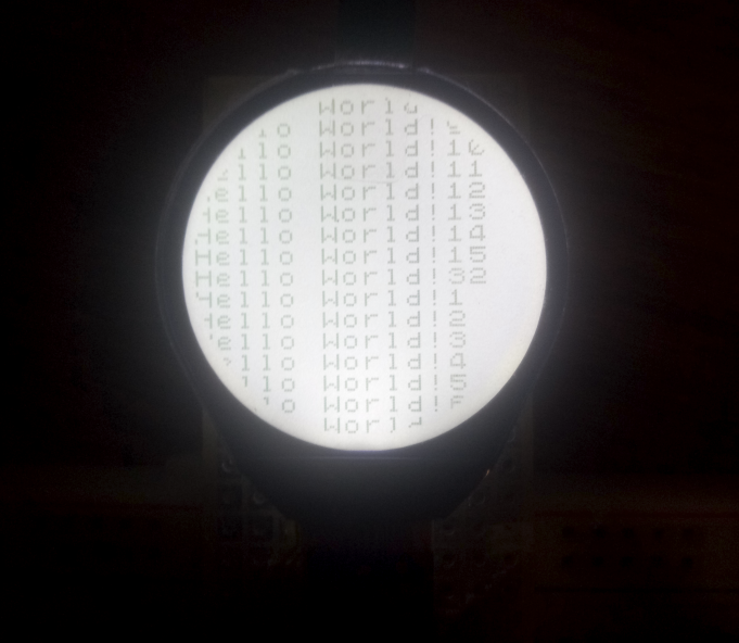
This display has two sections, bottom half and upper half, maybe you figured it out already, I've just animated "hello world" example to move one row at a time, so it wraps. Interesting that it goes till row 15, than "stops" and continues to draw on row 32 and then overflows.
monte-monte
on 21 Sep 2019
I think this has to be panel itself, with low contrast, when backlight is on.
Could be true...
continues to draw on row 32 and then overflows.
I think this is just the value 0. Can you test this? Where will row 0 end up?
olikraus
on 21 Sep 2019
Ah, yes, you're right. I forgot to start with 0, my bad:)
monte-monte
on 21 Sep 2019
"Integrated Solutions Technology" claims this driver to be very low power. It seems to be true, with backlight off displays consumes around 30uA while being updated. I think one can build a nice watch with this display...
monte-monte
on 21 Sep 2019
ill it
with backlight off displays consumes around 30uA while being updated
Nice. Is the display still readable?
I have added the start line command: https://github.com/olikraus/u8g2/blob/master/csrc/u8x8_d_ist7920.c#L126
Will your u8x8 test work correctly? Also U8g2 should be ok now.
If you took the original code u8x8_d_ist7920.c from the repo (including the flip mode commands), can you test the u8g2 flip mode example? Will it work correctly (the frame should be visible ... as much this is possible inside a circled display)?
olikraus
on 21 Sep 2019
Everything seems to work, including flip mode. One else thing to ask, can you adjust base contrast? I don't know how many other displays there using this driver, but for now I think it's safe to set contrast according to this particular one.
Nice. Is the display still readable?
Actually it looks better without backlight, in terms of contrast. On a bright day or under a ceiling light you will read it clearly.
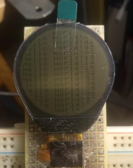
The only thing is it's pretty slow. You can see crystals fading in, switching off goes faster but still not as good as one could imagine. Adding to it low contrast makes this display sensible to proper UI without much animation.
I wonder if there is some settings that could affect this issue. I think we will have to wait for a seller to come back from vacation, maybe he will send me the right code and it will make some difference.
Anyway I am happy with what I have now. I've bought these for 5$ each, but while I was looking for the datasheet I've found them for 3$ from another manufacturer, outside of aliexpress. Also on alibaba you can find similar displays for around 2$ but they have hexagonal shape, still having round display area.
monte-monte
on 21 Sep 2019
Oh, I think I've messed up. So it seems that flip mode isn't working. I've just read what it suppose to do. In my case flip example sketch only rotates screen for 90 degree at a time.
monte-monte
on 21 Sep 2019
One else thing to ask, can you adjust base contrast?
oh, yes, done
flip mode isn't working
Hmm... did you use the u8x8 version? It just does the flip, nothing else. And also: did you use the latest version from the repo?
I wonder if there is some settings that could affect this issue.
Could be... I am still happy we reached such a good result within a short time. :-)
olikraus
on 21 Sep 2019
Oh, one more thing: I have not yet added proper sleep modes.
Is this required for your app? Shell we add this?
olikraus
on 21 Sep 2019
I've checked the latest version, flip mode works. But there is a typo on a line 126 - semicolon instead of comma.
What exactly sleep mode does? Reduces power consumption even more? I don't need it for my current project, but I wonder what difference would it make.
I am so grateful for your work, I didn't expect that you will help me with this so soon and basically 2 days later I have working code.
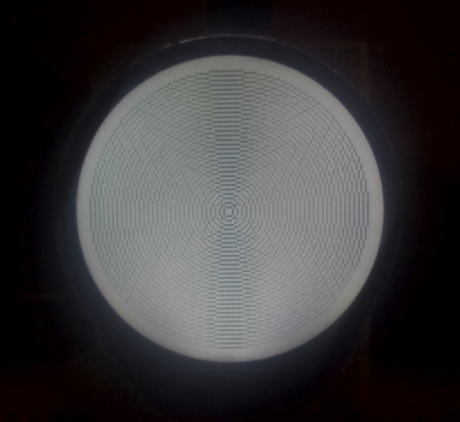
Here you have a photo of beautiful round moire on a round display :)
Thank you!
monte-monte
on 22 Sep 2019
But there is a typo on a line 126 - semicolon instead of comma.
Which file exactly?
What exactly sleep mode does? Reduces power consumption even more?
Probably yes. There is a sleep mode on and off sequence in the datasheet, which will shut down almost all of the charge pumps. At the moment I just send a display off with the powerdown command of U8g2.
Maybe sleep-in indeed is intended to further reduce power while keeping the display visible... not sure about this...
I will keep this as it is for now.
I didn't expect that you will help me with this so soon and basically 2 days later I have working code.
Thanks to you for giving my rapid feedback, pictures and further information while I worked on the updates... :-)
olikraus
on 22 Sep 2019
Which file exactly?
Found and fixed. Thanks!
olikraus
on 22 Sep 2019
Related issues
 hauwarea
·
5Comments
hauwarea
·
5Comments
 margce
·
7Comments
margce
·
7Comments
 BrickBee
·
3Comments
BrickBee
·
3Comments
 idreamsi
·
5Comments
idreamsi
·
5Comments
 Bonnie12
·
6Comments
Bonnie12
·
6Comments