Three.js: RingGeometry texture mapping
Description of the problem
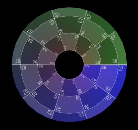
The default texture mapping for a RingGeometry object is unexpectedly linear. It would make the most sense for ME to render the map in polar coordinates: x=0 to 360 degrees, y=inner to outer radius. I've not yet learned how I can remap texture orientations.
EXAMPLE OBJECT
var saturnringTexture = new THREE.TextureLoader().load("../assets/textures/earth/saturnring.jpg");
var geoRing = new THREE.RingGeometry( 5 * 1.21, 5 * 2.27, 80 );
var matRing = new THREE.MeshBasicMaterial( { map: saturnringTexture, side: THREE.DoubleSide } );
var meshRing = new THREE.Mesh( geoRing, matRing );
meshRing.rotation.x=90/DEG_PER_RAD;
EXAMPLE IMAGE:
https://twitter.com/Tom_Ruen/status/1204521224883322880
Three.js version
- [ ] Dev
- [ ] r111
- [ ] ...
Browser
- [x] All of them
- [ ] Chrome
- [ ] Firefox
- [ ] Internet Explorer
OS
- [x] All of them
- [ ] Windows
- [ ] macOS
- [ ] Linux
- [ ] Android
- [ ] iOS
Hardware Requirements (graphics card, VR Device, ...)
 tomruen
All 21 comments
//Here's my workaround, while would be easier to apply to original mesh vertices inside the original class.
//EXAMPLE https://twitter.com/Tom_Ruen/status/1204604998316937218
var nring1=80;
var nring2=20;
var geoRing = new THREE.RingGeometry( 5*1.21, 5*2.27, nring1, nring2);
var matRing = new THREE.MeshBasicMaterial( { map: saturnringTexture, side: THREE.DoubleSide } );
var meshRing = new THREE.Mesh( geoRing, matRing );
meshRing.rotation.x=90/DEG_PER_RAD;
for(var yi=0; yi<nring2; yi++)
{
  var u0=yi/nring2;
  var u1=(yi+1)/nring2;
  for(var xi=0; xi<nring1; xi++)
  {
    var fi=2*(xi+nring1*yi);
    var v0=xi/nring1;
    var v1=(xi+1)/nring1;
    geoRing.faceVertexUvs[0][fi][0].x=u0; geoRing.faceVertexUvs[0][fi][0].y=v0;
    geoRing.faceVertexUvs[0][fi][1].x=u1; geoRing.faceVertexUvs[0][fi][1].y=v0;
    geoRing.faceVertexUvs[0][fi][2].x=u0; geoRing.faceVertexUvs[0][fi][2].y=v1;
    fi++;
    geoRing.faceVertexUvs[0][fi][0].x=u1; geoRing.faceVertexUvs[0][fi][0].y=v0;
    geoRing.faceVertexUvs[0][fi][1].x=u1; geoRing.faceVertexUvs[0][fi][1].y=v1;
    geoRing.faceVertexUvs[0][fi][2].x=u0; geoRing.faceVertexUvs[0][fi][2].y=v1;
  }
}
geoRing.uvsNeedUpdate=true;
Current: https://jsfiddle.net/abkmn7pv/
Your code: https://jsfiddle.net/km2bqctp/
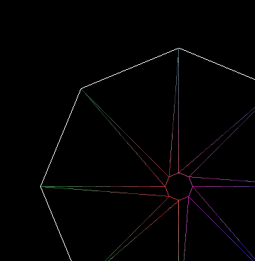
Um, your generated uvs do not look correct. The debug textures shows a strange discontinuation for each radial segment.
 Mugen87
on 11 Dec 2019
Mugen87
on 11 Dec 2019
Hi Michael,
I increased the segments and it looks fine, or at least as expected given the distortion from rectangular to an annulus.
tomruen
on 11 Dec 2019
If you want to change the way how RingGeometry generates it's texture coordinates, you need an approach that works with all supported parameterizations.
Mugen87
on 11 Dec 2019
@tomruen For your app, just use a texture having concentric rings.
 WestLangley
on 11 Dec 2019
WestLangley
on 11 Dec 2019
Mugen87, It seems funny you pick a texture with a 10x10 square grid marked on it, and then plot it as a 8x1 radial triangulation grid and complain it doesn't look good.
WestLangley, my application texture is actually 4096x1 pixels since radially symmetric. It would seem wasteful to make a 4096x4096 texture (actually larger, double from radius to diameter, plus empty center) to do the same thing. OTOH, it I had a texture map with features of Saturn's rings that were not symmetric (like ring braids), that approach might be useful.
Also, the default mapping function seems entirely undefined. I presume it to be applying on x,y extents, linearly as u,v in [0,1].
tomruen
on 11 Dec 2019
It seems funny you pick a texture with a 10x10 square grid marked on it, and then plot it as a 8x1 radial triangulation grid and complain it doesn't look good.
The problem is that your texture coordinates are distorted due to a wrong implementation.
Mugen87
on 11 Dec 2019
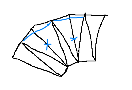
@Mugen87 I dont think it is possible to do better given this geometry without cheats:
note how outer and inner vertices in every 2nd triangle have the same angle in polar coords (mesh looks like this |\|\|\). Now if there was some angular offset in the inner circle (mesh looked like this /\/\/\) then better mapping could be done easily.
 makc
on 11 Dec 2019
makc
on 11 Dec 2019
It's tempting to add another triangle per segment...
 mrdoob
on 12 Dec 2019
mrdoob
on 12 Dec 2019
@mrdoob ...which he did:
I increased the segments and it looks fine
makc
on 12 Dec 2019
No, I meant to the generator.
Something like this:

mrdoob
on 12 Dec 2019
I don't see the triangulation as a problem. The issue is if you presume to want an "annulus" as a low order polygon, you're doing something weird, but if you're doing something weird the texture map should use the same weird. So if you have a octagonal triangulation, your texture map probably should have 8 intervals. Or the example texture has 10 intervals, so the triangulation should a multiple of 10 segments.
tomruen
on 15 Dec 2019
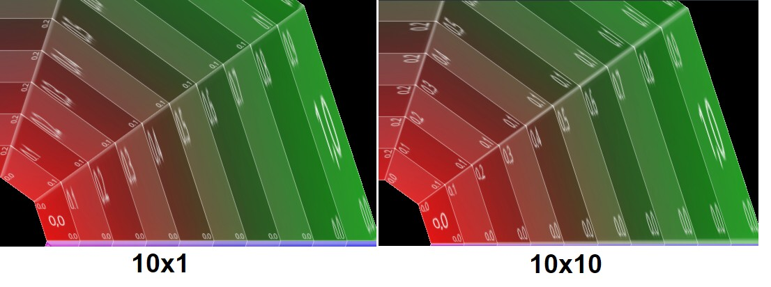
Maybe the triangulation (big/small) is having an effect, with nring1=10, but really it looks more like a bug in the rendering. The narrow triangles don't seem to draw the texture as expected. But if I also increase nring2=10, it looks much better, matching the 10x10 grid on the texture, and triangles come out good.
As far as I know, a proper implementation of a texture projection should NOT care how a trapezoidal domain is divided into triangles! Any triangulation should do!
I think I've seen other cases of coarse meshes (like a sphere geometry with fewer segments) that lose texture details around the poles with narrow triangles.
tomruen
on 15 Dec 2019
It looks like the triangulation does affect the mapping when scale changes from the texture to the geometry. There seems to be no solution besides more segments. Forcing a different triangulation doesn't help any more than having more segments. It is still unexpected since we know a quadrilateral uv mapping should work fine with a progressive scale change with radius, but any triangulation will distort it differently.
tomruen
on 15 Dec 2019
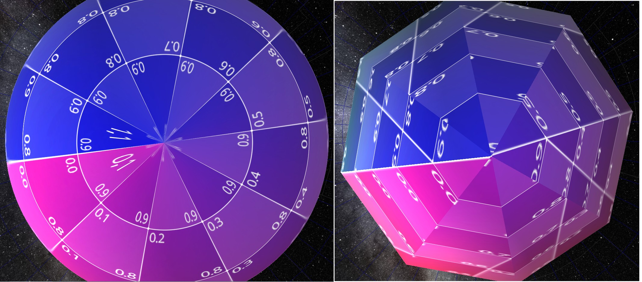
Here's the same effect on a sphere UV mapping. Mapping a flat lat/long map onto a sphere requires distortion and we know the poles look stretched on the flat map and correct on the sphere IF there are enough segments, but problems you you make an approximate sphere with a small number of segments.
var sphere=new THREE.SphereGeometry(1,8,2); // RIGHT IMAGE, an octagonal bipyramid really
tomruen
on 15 Dec 2019
@tomruen this is just uv being interpolated linearly in the triangle where it should be highly non-linear. in case of the ring, with different triangle layout you have a chance to orient the texture better, and the same applies to the sphere - the pole vertex longitude needs to be half-sum of triangle base longitudes.
makc
on 16 Dec 2019
Agreed, thus nonlinear UV mappings, both for spheres and rings need more triangles to be accurate. I'm pointing this out because my UV mapping was challenged as wrong. It is NOT.
tomruen
on 17 Dec 2019
@mrdoob you could as well do this:
*cough... /\\/\\/\\/
makc
on 17 Dec 2019
@tomruen Your uvs look pretty good for a highly-tesselated circular ring. (Just not so good for an octagon.)
WestLangley
on 17 Dec 2019
@makc True, just offsetting the outer ring.
Wouldn't thing get complicated when taking thetaStart and thetaLength into account?
mrdoob
on 17 Dec 2019
@makc, you're right a phase shift on alternate radii would be more symmetric, just add a +(j%2)/2 phase shift, BUT this is a different geometry for small segments, if odd number of radial segments, basically an antiprism rather than prism. Still the current prism isn't a prism with quad sides, but a triangulated into a twisted antiprism!
https://threejs.org/docs/#api/en/geometries/RingGeometry
for ( j = 0; j <= phiSegments; j ++ ) {
    for ( i = 0; i <= thetaSegments; i ++ ) {
        // values are generate from the inside of the ring to the outside
        segment = thetaStart + (i+(j%2)/2) / thetaSegments * thetaLength;
        // vertex
        vertex.x = radius * Math.cos( segment );
        vertex.y = radius * Math.sin( segment );
..
tomruen
on 17 Dec 2019
Related issues
 fuzihaofzh
·
3Comments
fuzihaofzh
·
3Comments
 jlaquinte
·
3Comments
jlaquinte
·
3Comments
 akshaysrin
·
3Comments
akshaysrin
·
3Comments
 scrubs
·
3Comments
scrubs
·
3Comments
 boyravikumar
·
3Comments
boyravikumar
·
3Comments