Tasmota: Add support for a Second BH1750 on i2c bus
PROBLEM DESCRIPTION
Second BH1750 detected as DHT12 on i2c bus.
REQUESTED INFORMATION
- [x] Read the Contributing Guide and Policy and the Code of Conduct
- [x] Searched the problem in issues
- [x] Searched the problem in the docs
- [x] Searched the problem in the forum
- [x] Searched the problem in the chat
- [x] Device used (e.g., Sonoff Basic): Wemos D1 Mini
- [x] Tasmota binary firmware version number used: 8.2.0.3
- [x] Pre-compiled
- [ ] Self-compiled
- [ ] IDE / Compiler used: _____
- [x] Flashing tools used: Tasmotizer
- [x] Provide the output of command:
Backlog Template; Module; GPIO 255:
17:56:59 MQT: stat/wemospadlas/RESULT = {"NAME":"Generic","GPIO":[255,255,255,255,255,255,255,255,255,255,255,255,255],"FLAG":15,"BASE":18}
17:57:00 MQT: stat/wemospadlas/RESULT = {"Module":{"18":"Generic"}}
17:57:00 MQT: stat/wemospadlas/RESULT = {"GPIO0":{"0":"None"},"GPIO1":{"0":"None"},"GPIO2":{"0":"None"},"GPIO3":{"0":"None"},"GPIO4":{"6":"I2C SDA"},"GPIO5":{"5":"I2C SCL"},"GPIO9":{"0":"None"},"GPIO10":{"0":"None"},"GPIO12":{"0":"None"},"GPIO13":{"0":"None"},"GPIO14":{"0":"None"},"GPIO15":{"0":"None"},"GPIO16":{"0":"None"}}
TO REPRODUCE
Running Tasmota 8.2.0.3 on a Wemos D1 Mini.
Have two BH1750 and one VEML6070 connected to the I2C bus. The second BH1750 has ADDR pin connected to 3V3 in order to be at address 0x5C.
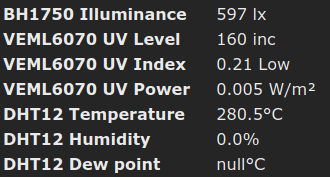
I2CScan returns Device(s) found at 0x23 0x38 0x39 0x5c which seems good.
First BH1750 at address 0x23 shows correct data, so does the VEML6070.
The second BH1750 at address 0x5C is detected as DHT12 (and consequently errorneous values are displayed).
Noticed in the docs that DHT12 and BH1750 can use the same address 0x5C.
I disabled the DHT12 driver by issuing I2cDriver41 0 but all that happened was that the DHT12 values disappeared from the interface and MQTT; however it didn't bring the second BH1750 up.
When I disconnect the first BH1750 at address 0x23, and only the second one remains at address 0x5C, that is detected correctly. Naturally when I disconnect the second one and re-connect the first one that is also detected correctly. The problem occurs when both BH1750 are connected at the same time.
EXPECTED BEHAVIOUR
See the values of the two separate BH1750 correctly, among the values of VEML6070. Don't detect the second BH1750 as DHT12.
SCREENSHOTS
 nagyrobi
All 25 comments
Hi,
Looking at the driver, only one BH1750 is supported at a time. You can use it in 0x23 or in 0x5c. Both at the same time are not supported. The driver was designed that way.
Adding the label Feature Request to see if someone is interested on working on adding dual support for the driver. Thanks.
 ascillato2
on 11 Apr 2020
ascillato2
on 11 Apr 2020
Just for curiosity on your use case, why you need 2 BH1750 on the same Wemos D1 Mini ?
 ascillato
on 11 Apr 2020
ascillato
on 11 Apr 2020
One is on the roof/chimney, facing South in a secure location where no other light sources or shadows may interfere with the measurement. It's placed in a waterproof casing together with an UV sensor. This is for general light and radiation level detection (regardless of Sun position).
The other one is placed lower, in a place where we can especially monitor for shadows of the building roof. This is for detection of Sun movement. I can make a rule to bring down the covers when the sun starts to shine onto that certain part of the building - but avoid doing that when it's cloudy etc.
These sensors are all wired up into the same place. Why use two Wemoses when one could do the job aswell?
Actually I wasn't aware that two BH1750 in the same time are not supported. As I've read through the docs, most sensors where address can be set with a jumper wire support that. I don't recall BH1750 missing this. And actually I could make use of three connected like this...
nagyrobi
on 11 Apr 2020
This issue has been automatically marked as stale because it has not had recent activity. It will be closed if no further activity occurs. Thank you for your contributions.
![stale[bot] picture](https://avatars3.githubusercontent.com/in/1724?v=4&s=40) stale[bot]
on 7 May 2020
stale[bot]
on 7 May 2020
+1
nagyrobi
on 8 May 2020
@nagyrobi
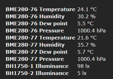
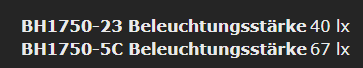
you can try my fork for support of 2 BH1750.
It's not the best implementation but it works for initial testing.
You can adjust the Resolution with commands:
BH1750_0_res
BH1750_1_res
the parameters are the same as before.
 device111
on 30 May 2020
device111
on 30 May 2020
Perfect!
device111
on 1 Jun 2020
Brilliant :)
Thanks,
Richie
 RichieRogers
on 1 Jun 2020
RichieRogers
on 1 Jun 2020
can someone explain me how to, two BH1750s are wired? Do I have to connect ADDR to GND on one BH1750?
Thanks
 T0RST3N
on 21 Jun 2020
T0RST3N
on 21 Jun 2020
can someone explain me how to, two BH1750s are wired? Do I have to connect ADDR to GND on one BH1750?
Thanks
Hi,
It depends on the module you have.
Some are pre configured to one address, while other modules use the other one.
I would suggest you make sure you buy two identical modules and make sure both are configured differently (one pulled to 3.3v, the other to GND)
Thanks,
Richie
RichieRogers
on 21 Jun 2020
Hi, Richi,
thanks for the quick answer. i have two identical bh1750.
do you mean one BH1750 must ADDR on 3,3V and with the other BH1750 sensor ADDR on GND.
Do i connect both BH1750 in parallel to the wemos mini???
thanks a lot
Torte
T0RST3N
on 21 Jun 2020
Yes.
nagyrobi
on 21 Jun 2020
Yes Perfect! THANK YOU!!
T0RST3N
on 22 Jun 2020
Hi,
I'm just trying to run an BH1750 on a Sonoff Basic module with precompiled Tasmota v8.3.1 Fred (from github).
Wireing seems to be ok(?) When using the console with the command 'I2CScan' the module returns:
00:05:02 MQT: /SONOS/EG/AZ/Play3.AZ/stat/RESULT = {"I2CScan":"Device(s) found at 0x5c"}
Acutally ADDR is connected to the VCC, when connecting ADDR to GND the address changes to 0x23 as described above.
But anyway the main menue do not show any sensor at all....
So I've red that I might have to "enable" the I2C-Driver so I tried I2CDriver11 1 on console with the output:
18:17:46 MQT: /SONOS/EG/AZ/Play3.AZ/stat/RESULT = {"I2CDriver":"!7"}
.... whatever that means .... I would have expected somthing like this: ... (I2CDriver":"11")?
Disableing DHT12 driver by using I2cDriver41 0, like @nagyrobi mentioned, did not change anything.
Using another board of the same type didn't help.
Maybe one of the "lightning experts" here can help me?
Best regards
Joe
 JoeWiseman
on 6 Jul 2020
JoeWiseman
on 6 Jul 2020
you must use tasmota-sensors.bin.
All other precompiled binarys don't have BH1750 support.
device111
on 6 Jul 2020
Thanks a lot @device111!!!
@arendst or someone else from the doumentation-team: Would be good to mention that in the I2C-section:
https://tasmota.github.io/docs/I2CDevices/
Thanks to all who keep this powerfull tool working and growing!!!
JoeWiseman
on 6 Jul 2020
you mix it up a little. The supported sensors are in the docs and the activated sensors in the precompiled Versions are in https://github.com/arendst/Tasmota/blob/development/BUILDS.md
device111
on 6 Jul 2020
Yes, @device111 you might be right .... But as a "non-native-Tasmoti" ;-) it is hard to get through to the right topics and pages on those two sites github.com and tasmota.github.io/docs/
So for a better understanding the BUILDS.md might be linked from the I2C-section of the docs?
That might be helpful for other people to get the right build for their use.
But anyway - thanks to you all for listening and helping!
JoeWiseman
on 9 Jul 2020
Dear folks, i have a question regarding the i2c bus of a nodemcu. I want to connect 2 sensors to this bus, the BH1750 lux sensor. By connecting the addr pin to the 3.3v pin I create a second bus address. when I run the i2cscan in tasmota, I also get to see these 2 addresses. No problem so far. but now i can't read the values anywhere. Can anyone tell me how i can get this done?
 vlak6613
on 11 Sep 2020
vlak6613
on 11 Sep 2020
what addresses do you see?
device111
on 11 Sep 2020
0x23 and 0x5C
vlak6613
on 11 Sep 2020
Have you tried tasmota-sensors.bin?
device111
on 11 Sep 2020
I read about that. I now use the tasomata.bin. I'm going to give this a try with the sensor.bin. I'll let you know if it worked.
Or do I have to do something with this https://tasmota.github.io/docs/I2CDevices/ ??
vlak6613
on 11 Sep 2020
i tried to update this sensor firmware, but it doesn't work.
I can see the sensor in the console.
{"I2CScan": "Device (s) found at 0x23"}.
But I don't see it in the main page of tasmota.
vlak6613
on 12 Sep 2020
so, there is no issue from Tasmota.
It works with tasmota-sensors.bin.
You can try Reset 4 to load defaults. If not, please go to the Tasmota support chat on discord. May somebody can help you.
device111
on 12 Sep 2020
Related issues
 he-so
·
3Comments
he-so
·
3Comments
 garret
·
3Comments
garret
·
3Comments
 esp32x
·
3Comments
esp32x
·
3Comments
 luisfpinto
·
3Comments
luisfpinto
·
3Comments
 wirelesssolution
·
3Comments
wirelesssolution
·
3Comments
Most helpful comment
One is on the roof/chimney, facing South in a secure location where no other light sources or shadows may interfere with the measurement. It's placed in a waterproof casing together with an UV sensor. This is for general light and radiation level detection (regardless of Sun position).
The other one is placed lower, in a place where we can especially monitor for shadows of the building roof. This is for detection of Sun movement. I can make a rule to bring down the covers when the sun starts to shine onto that certain part of the building - but avoid doing that when it's cloudy etc.
These sensors are all wired up into the same place. Why use two Wemoses when one could do the job aswell?
Actually I wasn't aware that two BH1750 in the same time are not supported. As I've read through the docs, most sensors where address can be set with a jumper wire support that. I don't recall BH1750 missing this. And actually I could make use of three connected like this...