Have you looked for this feature in other issues and in the docs?
Is your feature request related to a problem? Please describe.
_A clear and concise description of what the problem is._
I would like to order the new "Shelly Dimmer" and currently do not see a template. Has anyone ever tested the device or even run it with a different setting from another device?
Describe the solution you'd like
_A clear and concise description of what you want to happen._
Describe alternatives you've considered
_A clear and concise description of any alternative solutions or features you've considered._
Additional context
_Add any other context or screenshots about the feature request here._
(Please, remember to close the issue when the problem has been addressed)
 bloodhound83
All 262 comments
Shelly didn't start shipping those devices. No one have them, so we don't know if Tasmota can be flashed or not on them. Anyway, The stock firmware of Shelly supports MQTT, so if Tasmota don't work, you can still use them with your Home Automation Software.
I have pre-ordered those a month ago, so I will test them as soon as they arrive.
 ascillato
on 12 Nov 2019
ascillato
on 12 Nov 2019
@ascillato thank you for your quick answer.
I received my shipping message yesterday, so I assume that some devices have been shipped. But i guess you are right, i have only to wait a couple of days / weeks to get an answer...
good hint regarding the mqtt support from the stock firmware....
bloodhound83
on 12 Nov 2019
:+1:
 ascillato2
on 12 Nov 2019
ascillato2
on 12 Nov 2019
My shelly dimmers arrived today. Have you had any time to see if Tasmota can be flashed on to them? Sorry to bother you.
 jj-uk
on 25 Nov 2019
jj-uk
on 25 Nov 2019
Hi,
Mine have arrived too. It has an ESP8266, so it might be possible to use Tasmota on it, but will require some more research due to it uses several other chips for controlling the dimming.
So, please be patient ;)
ascillato
on 26 Nov 2019
Some high res photos provided by @Dino on Discord - for future reference:
https://onedrive.live.com/?authkey=%21AEmy6Ok03JXOMbk&id=CA999BBC242363E5%21115610&cid=CA999BBC242363E5
 meingraham
on 26 Nov 2019
meingraham
on 26 Nov 2019
Maybe an email to their support dept. Asking for a simple sketch to demo dimming? Can't hurt to ask...
They'll sell more once it's been tasmotafied. :D
jj-uk
on 26 Nov 2019
I had two delivered over the weekend along with a Shelly 1PM. Got tasmota successfully flashed on the 1PM, but no joy with the dimmers. I was using the diagram from the Shelly site for the header pin-outs but the programmer could not connect. This evening I wired up both dimmers and set them up with the Shelly software and new firmware was available, so have updated them but not tried to re-flash yet. D
 djhk739
on 26 Nov 2019
djhk739
on 26 Nov 2019
I successfully flashed the dimmer!
I also had the problem that the programmer could not connect, so I opened the housing and connected again. What I did ' wrong' at this time was that I connected all the wires in mirrored order by accident - and flashing suddenly succeeded. So my guess is that the documentation for the pin-out is wrong (mirrored).
I already requested the GPIO mapping to configure Tasmota but did not get a reply so far...
 SwedishChef
on 26 Nov 2019
SwedishChef
on 26 Nov 2019
Great news SwedishChef, when you say ‘mirrored’ do you mean they’ve got ‘top to bottom’ mixed up? D
djhk739
on 26 Nov 2019
The problem is that after opening the housing and flashing I recognized that the device was turned around 180 degrees compared to the pin-out picture on shell home page.
As I still connected the needed wires as described, it was most probably 'top-to-bottom mixed up'. Give it a try :-)
I already sent a message to Shelly to get this clarified.
SwedishChef
on 27 Nov 2019
Yup, got mine flashed as well, now moving on to the GPIO assignments.
djhk739
on 27 Nov 2019
@djhk739 please share your results for GPIO assignment here - many thanks.
PS: still no answer from shell.org regarding this ;-(
SwedishChef
on 28 Nov 2019
I've sent them an email re. tasmota template support 2 days ago as well, but no replay so far.
Usually they are pretty fast on replying.
 kovaga
on 29 Nov 2019
kovaga
on 29 Nov 2019
I've sent them an email re. tasmota template support 2 days ago as well, but no replay so far.
Usually they are pretty fast on replying.
Where can I get this template? What's the current status, please?
 phatina
on 30 Nov 2019
phatina
on 30 Nov 2019
There is no Tasmota template for shelly dimmer at this moment. It requires more code modifications and reverse engineering. It will take some time on being developed.
As soon as it becomes available, it is going to be announced here and in the Tasmota support chat.
By now, you can use Shelly Dimmer with stock firmware. It has mqtt support and there is also an automatic discovery for shelly devices if you use home assistant with hacs component.
ascillato
on 30 Nov 2019
Thanks a lot for your efforts! Highly appreciated.
 bastian987
on 3 Dec 2019
bastian987
on 3 Dec 2019
Anyone heard back from Shelly yet? I had a reply to my request for the source code and/or schematics as the product is sold as "open-source" (written on the box packaging).
Turns out it's not open-source at all and they're not going to give me the code :/
So I've asked for an example sketch to highlight how to perform dimming instead....
jj-uk
on 5 Dec 2019
Just for me to understand the problem:
Why configuring function PWMx to the corresponding GPIO pin via tasmota template does not work in case of Shelly dimmer? Do they use some different (non-standard) approach to dim the output?
SwedishChef
on 5 Dec 2019
As explained in previous comments. Shelly dimmer has other mcu to control dimming. It requires a new driver to be coded and a lot of reverse engineering. Tasmota is not going to work as it is now.
ascillato
on 5 Dec 2019
Anyone heard back from Shelly yet? I had a reply to my request for the source code and/or schematics as the product is sold as "open-source" (written on the box packaging).
Turns out it's not open-source at all and they're not going to give me the code :/
So I've asked for an example sketch to highlight how to perform dimming instead....
Aaah, I asked them the same question but with no answer.
phatina
on 5 Dec 2019
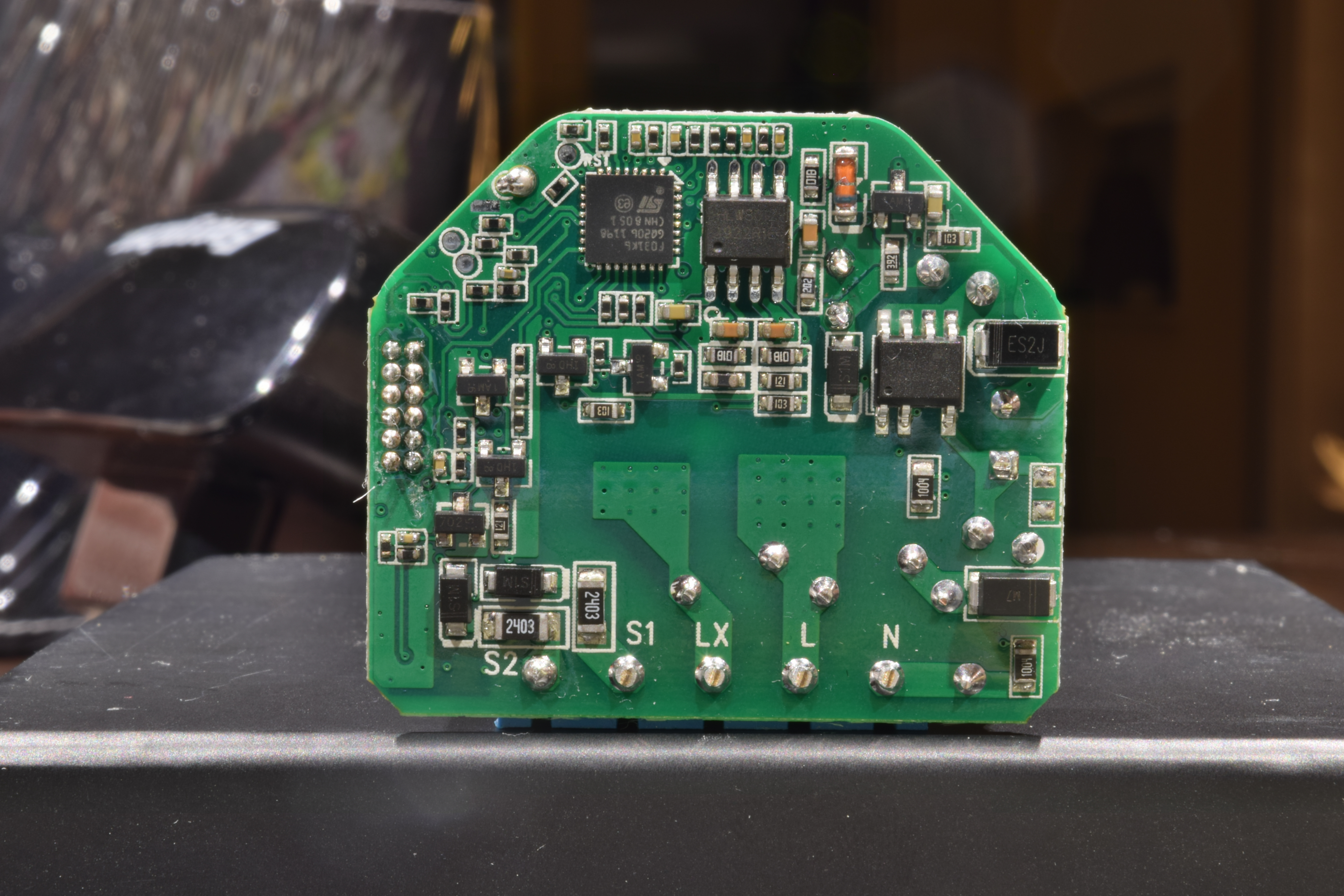
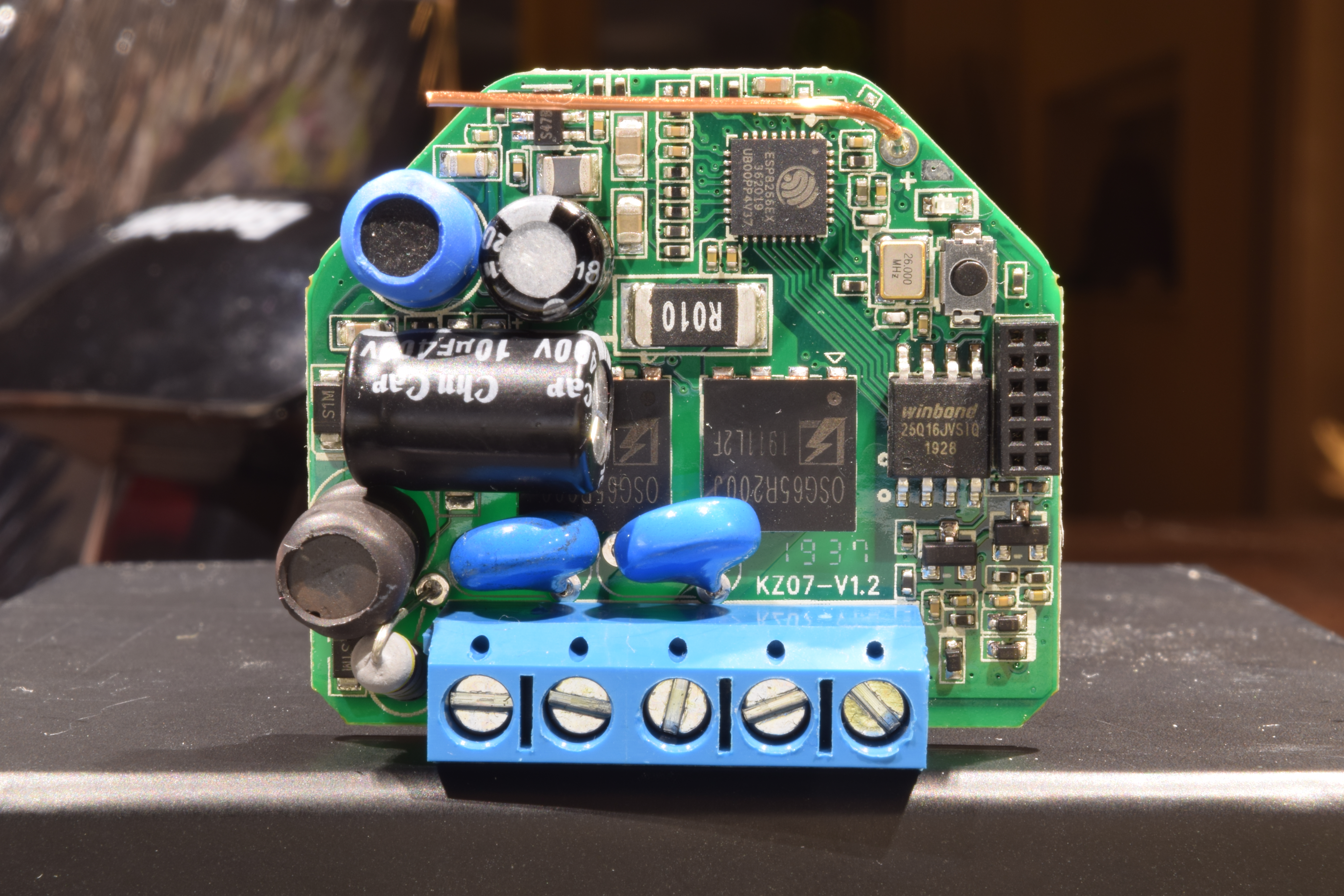
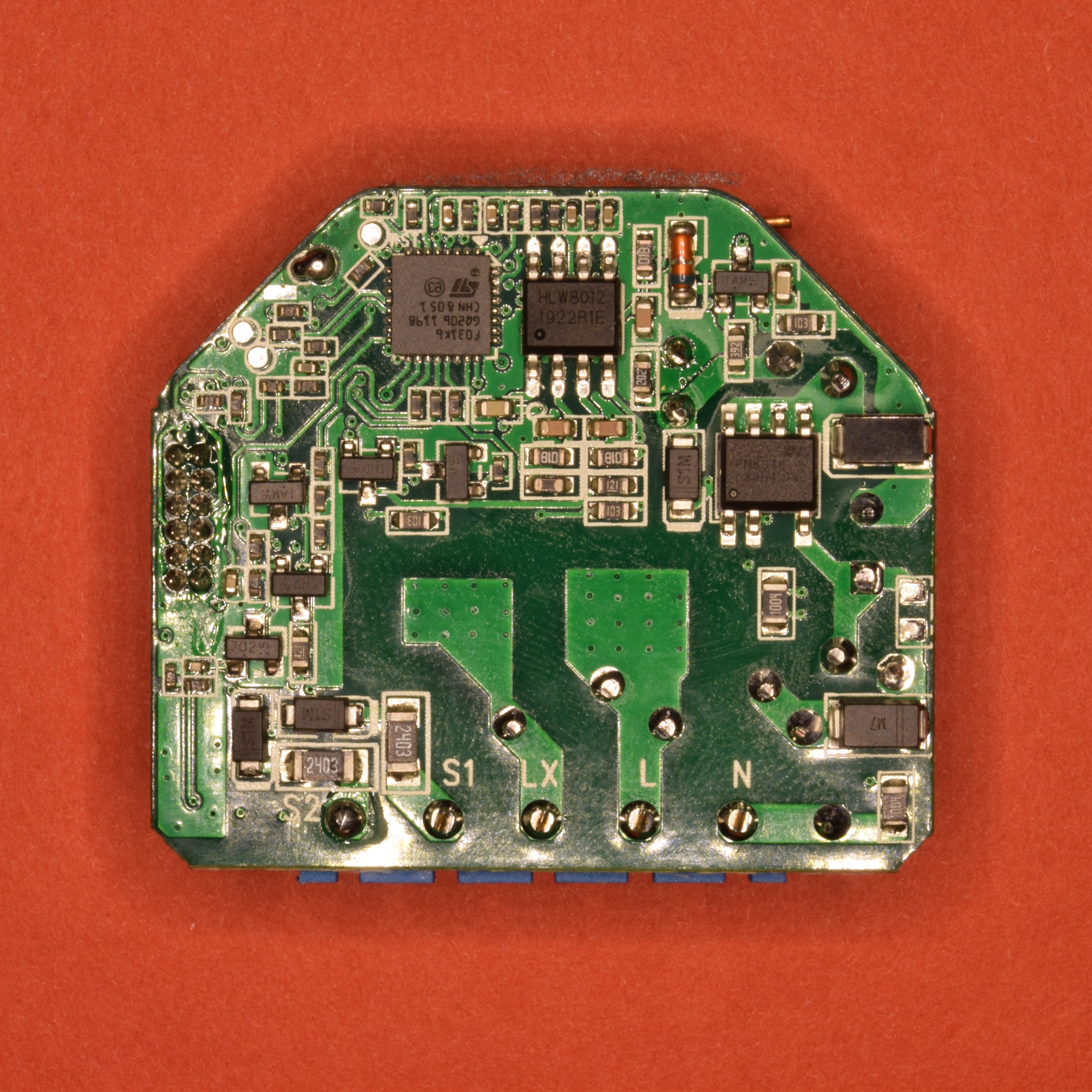
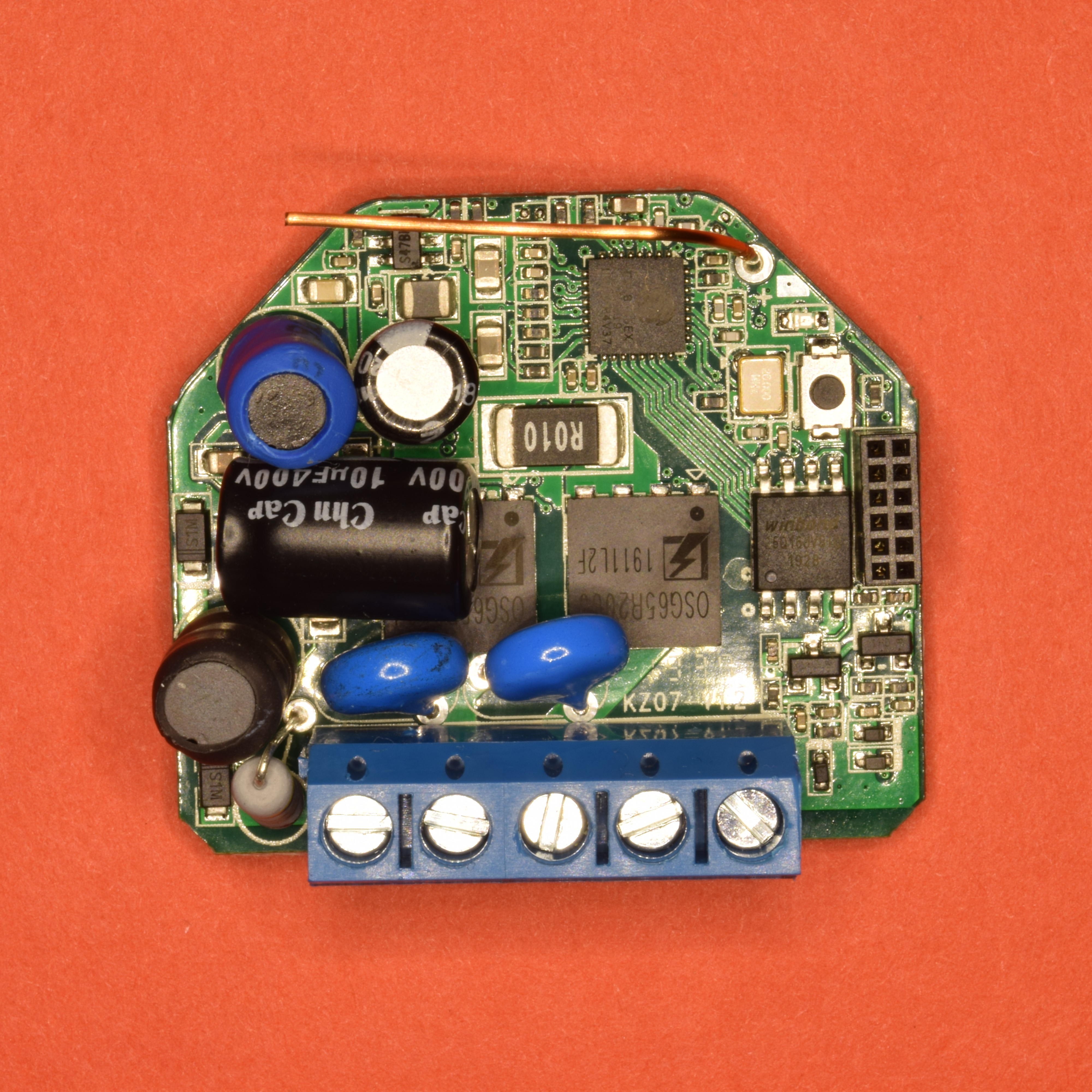
Indeed, the pinout reference on the official Shelly website is wrong. I figured out most of the connections of the second (outer) row of the header on the PCB. The right (inner) row corresponds to the flashing connections of the ESP8266, the outer row for the STM32F031K6.
Did someone figure out the communication between the ESP and the MCU? Serial? Why did Shelly decide to breakout GPIO2 (U1TX) of the ESP on the header?


 mgoeller
on 23 Dec 2019
mgoeller
on 23 Dec 2019
an STM32 with all flash/debug pins broken out ... interesting!
 joba-1
on 23 Dec 2019
joba-1
on 23 Dec 2019
I followed the esp8266 rx/tx traces and both are connect via 200R resistors to the stm32 PA9/PA10.
So I'm pretty sure both MCUs use the uart for communication.
Did someone manage to dump the flash of the esp? I'm unable to connect with esptool.py.
 mgerald21
on 27 Dec 2019
mgerald21
on 27 Dec 2019
Snooping the esp gpio whilst sending dim commands would be a good start. My logic analyser is not mains rated so I can't do this.
Anyone have a scope that can record ?
jj-uk
on 2 Jan 2020
I did make some progress ...
I was able to read the esp dimmer firmware with esptool, but stm32 needs to be held in reset state by keeping NRST on ground.
Digging into firmware shows, that shelly dimmer is based on rBoot with dual image support and 256k spiffs. spiffs holds an stm.bin file which is very likely an stm32 firmware image!? Maybe shelly dimmer also supports OTA update of the stm32 MCU?
mgerald21
on 2 Jan 2020
I really like these dimmers. On a side note, I have a total of 300W worth of LEDs that need to be dimmed on a single circuit. The shelly dimmer is rated for 200-220W max. It looks like the FET doing the dimming is the OSG65R200J and there are two of them on the board. Does anyone have a suggestion for another mosfet in a similar form factor that is rated for higher power? Would a placing a heatsink on top of the existing mosfets help disspate the extra 100W that I need? The datasheet for the OSG65R200J shows a max power dissipation value of 151W for each mosfet.
 Akeid
on 5 Jan 2020
Akeid
on 5 Jan 2020
@Akeid offtopic, please address those questions to the Tasmota support chat.
Thanks.
Support Information
See Docs for more information.
See FAQ for common questions/answers and links if none of your question is in the list
See Chat for more user experience.
See Community for forum.
See Code of Conduct
ascillato2
on 5 Jan 2020
The ones of you that have managed to flash the Shelly Dimmer, did you do any trick to flash it? Are you sure that the GPIO is correct?
I can't connect to mine, have 6 of them and can't connect to anyone of them.
I've flashed atleast 20 other Shelly devices, so I know how to flash them.
Edit: Found it out, VCC has to be powered with 5V and not 3.3V as usual for ESP8266.
Then it flashed as it should.
 emilhetty
on 7 Jan 2020
emilhetty
on 7 Jan 2020
Edit: Found it out, VCC has to be powered with 5V and not 3.3V as usual for ESP8266.
Then it flashed as it should.
And then you can simply control the dimmer via Tasmota as you do with regular ESP8266 devices? Sorry if that's a stupid question, I'm quite new to this.
 jan-koch
on 8 Jan 2020
jan-koch
on 8 Jan 2020
To connect to the device:
Hookup the device as @mgoeller pictured. Connect GPIO0 to GND then plug the usb device in. Wait a second or so and then disconnect GPIO0 from GND.
Read the flash
esptool.py --port /dev/ttyUSB0 --baud 115200 read_flash 0x00000 0x400000 backup.img
Edit: Found it out, VCC has to be powered with 5V and not 3.3V as usual for ESP8266.
Then it flashed as it should.
Connect 3.3V is enough.
 edge90
on 8 Jan 2020
edge90
on 8 Jan 2020
Edit: Found it out, VCC has to be powered with 5V and not 3.3V as usual for ESP8266.
Then it flashed as it should.And then you can simply control the dimmer via Tasmota as you do with regular ESP8266 devices? Sorry if that's a stupid question, I'm quite new to this.
No, you could not, the Shelly Dimmer is not supported yet.
The Shelly Dimmer is much more complicated than the other Shelly devices since it has a second mcu.
emilhetty
on 9 Jan 2020
emilhetty
on 9 Jan 2020
The BOOT0 pin on the stm32 seems like it's connected to pin 17 (VDDPST) on the esp8266.
edge90
on 9 Jan 2020
@edge90: are sure about the BOOT pin?
Stm32f031:
BOOT0=0 BOOT1=x - main flash memory boot
BOOT0=1 BOOT1=0 - system memory boot (boot loader)
BOOT0=1 BOOT1=1 - RAM memory
BOOT0=1 would always start the bootloader and esp8266 needs to transfer the firmware using UART. Well there is an stm.bin file in the SPIFFS of the esp so this sounds reasonable.
mgerald21
on 9 Jan 2020
Looks like i was wrong. Pin 9/GPIO14 (which i thought were pin 17) from the esp goes to a via hole. Kind of hard to see were it goes next.
Can post some better photos once i get my macro lens.
Added a gimp .xcf file with the front/back layered on top each other (use opacity to fade the top layer).
https://github.com/edge90/shelly_dimmer
Pinout
esp8266 specific
- A0 (pin 6) goes to a Thermistor.
- GPIO12 (pin 10) on the esp goes to the S1 switch (short S1 to ground makes the pin high, via PNP transistor)
- GPIO13 (pin 12) on the esp goes to the onboard button (on press pulls to low).
- GPIO14 (pin 9) on the esp goes to the S2 switch (short S2 to ground makes the pin high, via PNP transistor)
- GPIO15 (pin 13) on the esp goes to the onboard led.
stm32 specific
- PA0 (pin 6) on the stm32 goes to CF1 on HLW8012.
Common
- BOOT0 (pin 31) on the stm32 goes to GPIO4 (pin 16) on the esp.
- NRST (pin 4) on the stm32 goes to GPIO5 (pin 24) on the esp.
- PA9 (pin 17) on the stm32 goes to GPIO3 (pin 25) on the esp.
- PA10 (pin 20) on the stm32 goes to GPIO1 (pin 26) on the esp.
edge90
on 10 Jan 2020
Reversing the stm.bin blob confirms GPIOA PIN9, PIN10 are used for uart communication and it is set to 115200.
The UART IRQ handler looks relatively simple and straightforward (protocol should be simple), needs some more reversing though..
Here is my current ida db:
https://pastebin.com/xYuGs481
And the spiffs extracted stm.bin:
https://pastebin.com/Wtr5GAAT
 wichers
on 15 Jan 2020
wichers
on 15 Jan 2020
Just a short question ... has anyone considered to ask shelly for information about the communication protocol? They've shown a fair amount of community support in the past ..
edit: I've send them a mail. Will get back to you asap if I hear back from them
 KoljaWindeler
on 15 Jan 2020
KoljaWindeler
on 15 Jan 2020
@KoljaWindeler
Just a short question ... has anyone considered to ask shelly for information about the communication protocol? They've shown a fair amount of community support in the past ..
yes, multiple times in this thread. See previous comments:
https://github.com/arendst/Tasmota/issues/6914#issuecomment-558392370
https://github.com/arendst/Tasmota/issues/6914#issuecomment-562120992
https://github.com/arendst/Tasmota/issues/6914#issuecomment-558959497
https://github.com/arendst/Tasmota/issues/6914#issuecomment-559497593
ascillato
on 15 Jan 2020
Can one of the devs reopen this issue. There is already same progress and further investigation is ongoing.
mgerald21
on 15 Jan 2020
Still need to do more reversing.. UART packet structure (RX and TX) consists at least of something like:
uint16_t packet_checksum(uint8_t *buf, int len)
{
  int counter;
  uint16_t ret;

  counter = 0;
  ret = 0;
  while ( counter < len )
    ret += buf[counter++];
  return ret;
}

struct packet {
 uint8_t prefix; // 1
 uint8_t counter; // packet counter
 uint8_t command; // should be (1, 4), 2, 3, 16, 17, 32 or 48
 uint8_t size;
 uint8_t payload[xxx]; // payload is optional
 uint16_t checksum; // network endian
 uint8_t postfix; // 4
}  __attribute__((packed));

// checksum is calculated like this:
packet->checksum = packet_checksum(&packet->unknown_1, packet->size + 3);
Other GPIO pins used:
GPIOA PIN 8, 11
GPIOB PIN 2
Also bought a dimmer myself to connect a logic analyzer and see what does what. But I'm hoping that someone who already opened one can share some logic analyzer output of PA9 and PA10..
wichers
on 17 Jan 2020
PA8(18) and PA11(21) are probably driving the two power mosfets.
Energy monitoring is done via a HLW8012
STM ----- HLW8012
PA0(6) = CF1(7)
PA1(7) = CF(6)
mgerald21
on 17 Jan 2020
By looking at the images it seems like PA11 (which is pin 21 not 20) goes to the one of the mosfets.
edge90
on 18 Jan 2020
You're right - corrected that.
mgerald21
on 18 Jan 2020
Alright, I hooked up an opto-isolator to the TX line ....
Serial output starts with some garbage and rBoot startup message.
rBoot v1.2.1 - [email protected]
Flash Size: 16 Mbit
Flash Mode: DIO
Flash Speed: 40 MHz
rBoot Option: Big flashBooting rom 0 (0x8000).
After boot there is binary communication between the MCUs (capture.txt)
@wichers: your packet definition looks pretty right:
01 01 20 06 00 00 00 00 0f 00 00 36 04 - Start
01 02 10 00 00 12 04 - Polling
01 03 10 00 00 13 04 - Polling
01 04 10 00 00 14 04 - Polling
01 05 10 00 00 15 04 - Polling
01 06 10 00 00 16 04 - Polling
01 07 10 00 00 17 04 - Polling
01 08 10 00 00 18 04 - Polling
01 09 10 00 00 19 04 - Polling
01 0a 10 00 00 1a 04 - Polling
01 0b 02 06 fe 01 ff 00 00 00 02 11 04 - Dimming
01 0c 10 00 00 1c 04 - Polling
01 0d 01 02 e8 03 00 fb 04 - ??
01 0e 10 00 00 1e 04 - Polling
01 0f 02 06 00 00 f4 01 00 00 01 0c 04 - Dimming
01 10 10 00 00 20 04 - Polling
01 11 10 00 00 21 04 - Polling
01 12 02 06 e8 03 f4 01 00 00 01 fa 04 - Dimming
01 13 10 00 00 23 04 - Polling
01 14 02 06 00 00 f4 01 00 00 01 11 04 - Dimming
01 15 10 00 00 25 04 - Polling
01 16 10 00 00 26 04 - Polling
01 17 10 00 00 27 04 - Polling
- Byte 0 - always 0x01
- Byte 1 - packet counter
- Byte 2 - command
- 0x01 = ??
- 0x02 = dimming
- 0x10 = polling
- 0x20 = startup
- Byte3 - size
- Byte[size] - payload
- ByteN-2 = checksum 16 bit
- ByteN = always 0x04
Next I'll try to capture RX line in parallel.
mgerald21
on 18 Jan 2020
Don't know if this helps anyone but here's a dump of the stm32f031k6: https://github.com/edge90/shelly_dimmer/raw/master/stm32f031k6.bin
socat stdio /dev/ttyUSB0 | hexdump -C gave me the following while turning the light on:
000004d0  01 40 02 06 d4 03 ea 01  00 00 02 0a 04 01 40 02  |.@............@.|
000004e0  06 d4 03 ea 01 00 00 02  0a 04 01 40 02 06 d4 03  |...........@....|
000004f0  ea 01 00 00 02 0a 04 01  41 10 00 00 51 04 01 42  |........A...Q..B|
00000500  20 06 d4 03 00 00 0f 00  01 4e 04 01 42 20 06 d4  | ........N..B ..|
00000510  03 00 00 0f 00 01 4e 04  01 42 20 06 d4 03 00 00  |......N..B .....|
00000520  0f 00 01 4e 04 01 42 20  06 d4 03 00 00 0f 00 01  |...N..B ........|
00000530  4e 04...
and this when turning off:
00000000  00 00 00 00 00 00 00 00  00 00 00 01 62 10 00 00  |..p..a...q..b...|
00000610  72 04 01 63 02 06 00 00  ea 01 00 00 01 56 04 01  |r..c.........V..|
00000620  63 02 06 00 00 ea 01 00  00 01 56 04 01 63 02 06  |c.........V..c..|
00000630  00 00 ea 01 00 00 01 56  04 01 64 10 00 00 74 04  |.......V..d...t.|
00000640  01 65 20 06 00 00 00 00  0f 00 00 9a 04 01 65 20  |.e ...........e |
00000650  06 00 00 00 00 0f 00 00  9a 04 01 65 20 06 00 00  |...........e ...|
00000660  00 00 0f 00 00 9a 04 01  65 20 06 00 00 00 00 0f  |........e ......|
00000670  00 00 9a 04...
when changing the brightness level:
00000000  00 00 00 00 00 00 00 00  00 00 01 a2 10 00 00 b2  |................|
00000180  04 01 a3 10 00 00 b3 04  01 a4 01 02 00 00 00 a7  |................|
00000190  04 01 a4 01 02 00 00 00  a7 04 01 a4 01 02 00 00  |................|
000001a0  00 a7 04 01 a5 10 00 00  b5 04 01 a6 20 06 00 00  |............ ...|
000001b0  00 00 0f 00 00 db 04 01  a6 20 06 00 00 00 00 0f  |......... ......|
000001c0  00 00 db 04 01 a6 20 06  00 00 00 00 0f 00 00 db  |...... .........|
000001d0  04 01 a6 20 06 00 00 00  00 0f 00 00 db 04 01 a7  |... ............|
000001e0  10 00 00 b7 04....
brightness level 100%:
00000000  00 00 00 00 00 00 00 00  00 00 00 00 00 00 00 01  |...l ...........|
00000300  6d 10 00 00 7d 04 01 6e  10 00 00 7e 04 01 6f 10  |m...}..n...~..o.|
00000310  00 00 7f 04 01 70 01 02  00 00 00 73 04 01 70 01  |.....p.....s..p.|
00000320  02 00 00 00 73 04 01 70  01 02 00 00 00 73 04 01  |....s..p.....s..|
00000330  71 10 00 00 81 04 01 72  10 00 00 82 04 01 73 20  |q......r......s |
00000340  06 00 00 00 00 0f 00 00  a8 04 01 73 20 06 00 00  |...........s ...|
00000350  00 00 0f 00 00 a8 04 01  73 20 06 00 00 00 00 0f  |........s ......|
00000360  00 00 a8 04 01 73 20 06  00 00 00 00 0f 00 00 a8  |.....s .........|
brightness level 0%:
000009b0  00 01 46 01 02 00 00 00  49 04 01 46 01 02 00 00  |..F.....I..F....|
000009c0  00 49 04 01 46 01 02 00  00 00 49 04 01 47 10 00  |.I..F.....I..G..|
000009d0  00 57 04 01 48 10 00 00  58 04 01 49 20 06 00 00  |.W..H...X..I ...|
000009e0  00 00 0f 00 00 7e 04 01  49 20 06 00 00 00 00 0f  |.....~..I ......|
000009f0  00 00 7e 04 01 49 20 06  00 00 00 00 0f 00 00 7e  |..~..I ........~|
00000a00  04 01 49 20 06 00 00 00  00 0f 00 00 7e 04 01 4a  |..I ........~..J|
00000a10  10 00 00 5a 04...
Events while waiting for approx 30 sec (while not doing anything, each row is emitted every 5 sec or so):
00000310  01 0b 10 00 00 1b 04 01  0c 10 00 00 1c 04 01 0d  |................|
00000320  10 00 00 1d 04 01 0e 10  00 00 1e 04 01 0f 10 00  |................|
00000330  00 1f 04 01 10 10 00 00  20 04 01 11 10 00 00 21  |........ ......!|
00000340  04 01 12 10 00 00 22 04  01 13 10 00 00 23 04 01  |......"......#..|
00000350  14 10 00 00 24 04 01 15  10 00 00 25 04 01 16 10  |....$......%....|
00000360  00 00 26 04 01 17 10 00  00 27 04 01 18 10 00 00  |..&......'......|
00000370  28 04 01 19 10 00 00 29  04 01 1a 10 00 00 2a 04  |(......)......*.|
00000380  01 1b 10 00 00 2b 04 01  1c 10 00 00 2c 04 01 1d  |.....+......,...|
00000390  10 00 00 2d 04 01 1e 10  00 00 2e 04 01 1f 10 00  |...-............|
000003a0  00 2f 04 01 20 10 00 00  30 04 01 21 10 00 00 31  |./.. ...0..!...1|
000003b0  04 01 22 10 00 00 32 04  01 23 10 00 00 33 04 01  |.."...2..#...3..|
000003c0  24 10 00 00 34 04 01 25  10 00 00 35 04 01 26 10  |$...4..%...5..&.|
000003d0  00 00 36 04 01 27 10 00  00 37 04 01 28 10 00 00  |..6..'...7..(...|
000003e0  38 04 01 29 10 00 00 39  04 01 2a 10 00 00 3a 04  |8..)...9..*...:.|
000003f0  01 2b 10 00 00 3b 04 01  2c 10 00 00 3c 04 01 2d  |.+...;..,...<..-|
00000400  10 00 00 3d 04 01 2e 10  00 00 3e 04 01 2f 10 00  |...=......>../..|
Looks like the data is transmitted over rx/tx on the header as well.
The update firmware process doesn't print anything. The output only shows rBoot boot message (board was reset).
TL;DR OUTDATED INFO SEE NEXT POST.
0%   - 01 bc 20 06 0a 00 02 00 0f 00 00 fd 04 (slide to 0% while on)
0%   - 01 32 20 06 0a 00 02 00 0f 00 00 73 04 (slider was at 0%, switched on)
0%   - 01 58 20 06 00 00 02 00 0f 00 00 8f 04 (slider was at 0%, switched off)
~50% - 01 cc 20 06 ea 01 02 00 0f 00 01 ee 04 (slide to ~50% while on)
~50% - 01 3f 02 06 ea 01 f5 00 00 00 02 27 04 (slider was at ~50%, switched on)
~50% - 01 4f 02 06 00 00 f5 00 00 00 01 4c 04 (slider was at ~50%, switched off)
100% - 01 e9 20 06 e8 03 02 00 0f 00 02 0b 04 (slide to 100% while on)
100% - 01 c0 02 06 e8 03 f4 01 00 00 02 a8 04 (slider was at 100%, switched on)
100% - 01 e3 02 06 00 00 f4 01 00 00 01 e0 04 (slider was at 100%, switched off)
100% - 01 f8 20 06 e8 03 02 00 0f 00 02 1a 04 (slide to 100% while on)
100% - 01 1e 20 06 00 00 02 00 0f 00 00 55 04 (side to 100% while off)
Got some more time to dig around. After the update the device stopped emitting this kind of data on the uart. Had to reflash it with my "old" dump to get it working again.
Dumped with socat stdio /dev/ttyUSB0 | hexdump -C -v.
From 100% to 0%
Off
01 12 01 02 00 00 00 15 04 (from 100% to 0% while off `#1`)
01 24 01 02 00 00 00 27 04 (from 100% to 0% while off `#2`)
01 57 01 02 00 00 00 5a 04 (from 100% to 0% while off `#3`)

01 ec 01 01 01 00 ef 04 (ack?)
On
01 85 01 02 0a 00 00 92 04 (from 100% to 0% while on `#1`)
01 a1 01 02 0a 00 00 ae 04 (from 100% to 0% while on `#2`)
01 bd 01 02 0a 00 00 ca 04 (from 100% to 0% while on `#3`)

01 d8 01 01 01 00 db 04 (ack?)
From 0% to 100%
Off
01 cb 01 02 00 00 00 ce 04 (from 0% to 100% while off `#1`)
01 e9 01 02 00 00 00 ec 04 (from 0% to 100% while off `#2`)
01 fc 01 02 00 00 00 ff 04 (from 0% to 100% while off `#3`)

01 8e 01 01 01 00 91 04 (ack?)
On
01 69 01 02 e8 03 01 57 04 (from 0% to 100% while on `#1`)
01 8a 01 02 e8 03 01 78 04 (from 0% to 100% while on `#2`)
01 a5 01 02 e8 03 01 93 04 (from 0% to 100% while on `#3`)

01 c0 01 01 01 00 c3 04 (ack?)
Toggle switch at 100%
Off
01 f4 02 06 00 00 f4 01 00 00 01 f1 04 (turn off while at 100% `#1`)
01 a0 02 06 00 00 f4 01 00 00 01 9d 04 (turn off while at 100% `#2`)
01 bb 02 06 00 00 f4 01 00 00 01 b8 04 (turn off while at 100% `#3`)

01 43 02 01 01 00 47 04 (ack?)
On
01 04 02 06 e8 03 f4 01 00 00 01 ec 04 (turn on while at 100% `#1`)
01 2e 02 06 e8 03 f4 01 00 00 02 16 04 (turn on while at 100% `#2`)
01 75 02 06 e8 03 f4 01 00 00 02 5d 04 (turn on while at 100% `#3`)

01 1c 02 01 01 00 20 04 (ack?)
Toggle switch at 0%
On
01 8c 01 02 0a 00 00 99 04 (turn on while at 0% `#1`)
01 cd 01 02 0a 00 00 da 04 (turn on while at 0% `#2`)
01 e4 01 02 0a 00 00 f1 04 (turn on while at 0% `#2`)

01 16 01 01 01 00 19 04 (ack?)
Off
01 74 01 02 00 00 00 77 04 (turn off while at 0% `#1`)
01 a7 01 02 00 00 00 aa 04 (turn off while at 0% `#2`)
01 b9 01 02 00 00 00 bc 04 (turn off while at 0% `#3`)

01 0a 01 01 01 00 0d 04 (ack?)
The "Polling"
01 77 10 00 00 87 04 `#1`
01 78 10 00 00 88 04 `#2`
01 7a 10 00 00 8a 04 `#3`

01 9f 10 0c 01 00 00 00 00 00 00 00 19 00 00 00 00 d5 04 (ack?)
01 a6 10 0c 01 00 00 00 00 00 00 00 19 00 00 00 00 dc 04 (another ack?)
Settings
~All of the following sequences are repeated 4 times for some reason.~
Pulling out the rx cable (rx from board) to the serial devices stops the repetition.
Set pulse mode to "trailing edge"
01 88 30 48 00 00 00 00 00 00 00 00 00 00 00 00
00 00 00 00 00 00 00 00 00 00 00 00 00 00 00 00
00 00 00 00 00 00 00 00 00 00 00 00 00 00 00 00
00 00 00 00 00 00 00 00 00 00 00 00 00 00 00 00
00 00 00 00 00 00 00 00 00 00 00 00 01 00 04

01 89 20 06 00 00 02 00 0f 00 00 c0 04

01 0a 30 01 01 00 3c 04 (ack first?)
01 0b 20 01 01 00 2d 04 (ack second?)
Set pulse mode to "leading edge"
01 e5 30 48 00 00 00 00 00 00 00 00 00 00 00 00
00 00 00 00 00 00 00 00 00 00 00 00 00 00 00 00
00 00 00 00 00 00 00 00 00 00 00 00 00 00 00 00
00 00 00 00 00 00 00 00 00 00 00 00 00 00 00 00
00 00 00 00 00 00 00 00 00 00 00 00 01 5d 04

01 e6 20 06 00 00 01 00 0f 00 01 1c 04

01 c9 30 01 01 00 fb 04 (ack first?)
01 ca 20 01 01 00 ec 04 (ack second?)
Start calibration
01 32 30 48 00 00 00 00 00 00 00 00 00 00 00 00
00 00 00 00 00 00 00 00 00 00 00 00 00 00 00 00
00 00 00 00 00 00 00 00 00 00 00 00 00 00 00 00
00 00 00 00 00 00 00 00 00 00 00 00 00 00 00 00
00 00 00 00 00 00 00 00 00 00 00 00 00 aa 04

01 33 04 02 00 00 00 39 04

01 34 30 01 01 00 66 04 (ack first?)
01 35 04 01 01 00 3b 04 (ack second?)
Delete calibration
01 88 30 48 00 00 00 00 00 00 00 00 00 00 00 00
00 00 00 00 00 00 00 00 00 00 00 00 00 00 00 00
00 00 00 00 00 00 00 00 00 00 00 00 00 00 00 00
00 00 00 00 00 00 00 00 00 00 00 00 00 00 00 00
00 00 00 00 00 00 00 00 00 00 00 00 01 00 04

01 9e 30 01 01 00 d0 04 (ack?)
Buttons fade rate
x1
01 27 20 06 00 00 02 00 05 00 00 54 04

01 60 20 01 01 00 82 04 (ack?)
x2
01 f0 20 06 00 00 02 00 0a 00 01 22 04

01 6d 20 01 01 00 8f 04 (ack?)
x3
01 11 20 06 00 00 02 00 0f 00 00 48 04

01 7b 20 01 01 00 9d 04 (ack?)
x4
01 39 20 06 00 00 02 00 14 00 00 75 04

01 8a 20 01 01 00 ac 04 (ack?)
x5
01 49 20 06 00 00 02 00 19 00 00 8a 04

01 96 20 01 01 00 b8 04 (ack?)
Hi, Ive also done some digging, setting the brightness seams to be very straight forward:
the 2 byte payload is brightness*10 in 2-byte little endian
e.g. 18% is 180 in dec, 00B4 in hex so the payload is B4 00.
So the complete message turn out as
01 9C 01 02 B4 00 01 53 04 = 0x01, id, cmd, len, payload, check, 0x04
That works for all brightness values, even "off" is simply 00 00 as brightness.
One thing to figure out is the response to the cmd 0x10.
Is see something like this
01 45 10 0C 01 00 B4 00 00 00 00 00 0F 00 00 00 01 25 04
I'd guess power consumption?
KoljaWindeler
on 20 Jan 2020
@edge90 thank you!
One thing to figure out is the response to the cmd 0x10.
It consists of 2 x uint16_t followed by 2 x uint32_t. The source of the second uint16_t and the last uint32_t are known to me, the others two values aren't, at the moment..
Does anyone know of a working stm32 uart arduino bootloader implementation? Or do we need to rewrite stm32flash (https://sourceforge.net/projects/stm32flash/) to arduino?
wichers
on 20 Jan 2020
The source of the second uint16_t and the last uint32_t are known to me, the others two values aren't, at the moment
would you share your knowledge?
KoljaWindeler
on 20 Jan 2020
second uint16_t is a copy from brightness value set in 0x01 or 0x20 packet
last uint32_t is a copy from the last uint16_t 0x20 packet, but is only copied from 0x20 packet handler when value < 100, this seems to be the fade rate as edge90 found out..
@edge90
..that pulse mode feature doesn't seem to be really 'processed' by the stm32 only a memcpy is done and answered with payload '1'
I think we are ready for prototyping something together, anyone building something already?
wichers
on 20 Jan 2020
@KoljaWindeler I had just realized that there was something wrong with my original attempt. Updated answer should be more accurate. Also I think your theory about the brightness is correct. If you take my "dim from 0% to 100% example above we have "e8 03" which would be 0x03e8 (1000/100%). Nice work!
@wichers strange. I need an oscilloscope so bad :/ I'm gonna start prototyping tomorrow, you too? I can test/review if you post a repo.
Does anyone know if we can connect AC power and use the GPIO stuff at the same time? Shelly 2.5 can't (https://github.com/arendst/Tasmota/wiki/shelly-2.5). I will probably program OTA to be on the safe side.
Regarding OTA flashing of the stm32, maybe we can get some insperation from https://github.com/csnol/STM32-OTA .
edge90
on 20 Jan 2020
What about starting a Wiki entry for the Shelly dimmer to collect all the current information?
mgerald21
on 21 Jan 2020
@edge90: absolutely no, pin headers on Shellies (1, 2, dimmer, etc ) are not isolated from main!!!! So GND on the header is somehow connect to mains and you must not use GPIO while connected to mains. That’s why I hooked up an optocoupler to sniff tax line!
mgerald21
on 21 Jan 2020
Just as a precautions: You can power the device totally fine by applying 3.3V to VCC on the header. That way you can easily sniff and test without any risk. I'll try to intercept the communication tonight.
My plan is to connect the esp8266 tx/rx lines from the dimmer to another esp8266 (emulation device) and to keep the stm in reset so it won't disturb the communication.
This way I'll make sure that my parser and message coder works correct and I'll be able to fake some 0x10 messages. I'll try to add some values into the first 32bit field and see if that changes the display of the wattage output (on the dimmer website).
I guess we can remove the original firmware once that's working, or is there anything that we don't know by now?
@edge90
What confuses me are your logs above. Have you sniffed tx and rx at the same time or one after the other? The reason I'm asking is this: My device shows identical IDs on tx and rx, as if the stm says: My response to your request with id 0x56 is this .. (message also starts with id 0x56).
So instead of
01 49 20 06 00 00 02 00 19 00 00 8a 04
01 96 20 01 01 00 b8 04 (ack?)
I see in my logs (sniffed tx and rx with two adapters simultaneously)
01 A4 20 06 00 00 02 00 19 00 00 8a 04
01 A4 20 01 01 00 b8 04
and yes... i'm fairly sure that is is some sort of ACK. Same ID, same cmd and payload is always 0x01.
Kolja
KoljaWindeler
on 21 Jan 2020
@KoljaWindeler that's how i got my data. However you won't get any power consuption reports with a value other than zero. That will require a load which in turn requires mains power.
edge90
on 21 Jan 2020
That will require a load which in turn requires mains power.
true, OR by intercepting it :) I really don't like open 220VAC
BUT if you have a safe setup and can grab some messages with the corresponding wattage from the UI please post them so we can have a look together if it's not obvious how the data are coded.
KoljaWindeler
on 21 Jan 2020
@KoljaWindeler regarding the ack. I didn't read them at the same time so the ack is a response for a later "request".
edge90
on 21 Jan 2020
ok, I'm almost afraid to ask .. but how did you manage to flash the non-stock firmware. Holding GPIO0 down isn't enough, I guess that the STM is driving the serial pins against my programmer. any tricks..
Intercepting didn't work. I was able to modify the hardware but the ESP never reacted on my messages ..
KoljaWindeler
on 21 Jan 2020
@KoljaWindeler See previous comment https://github.com/arendst/Tasmota/issues/6914#issuecomment-572265255
ascillato
on 21 Jan 2020
This is really odd .. I had to crank it up all the way to 5.4V to get it flashing. All other attempts failed .. good news: it turns off and on and the 0x10 cmd has some data. Bad news: dimming isn't working at the moment...
Edit: never mind .. I've posted to the wrong topic. Dimming works. On to the next challenge: wattage
KoljaWindeler
on 21 Jan 2020
ok, I need help .. I don't get it ..
0x384 -> 90%
dev98/r/trace Recv CMD: 0x10 Length: 0x0c -> 00 00 84 03   62 82 00 00   00 00 00 00
dev98/r/trace Recv CMD: 0x10 Length: 0x0c -> 00 00 84 03   0f 82 00 00   00 00 00 00
dev98/r/trace Recv CMD: 0x10 Length: 0x0c -> 00 00 84 03   70 82 00 00   00 00 00 00
dev98/r/trace Recv CMD: 0x10 Length: 0x0c -> 00 00 84 03   65 82 00 00   00 00 00 00
dev98/r/trace Recv CMD: 0x10 Length: 0x0c -> 00 00 84 03   59 82 00 00   00 00 00 00 -> 33369
dev98/r/trace Recv CMD: 0x10 Length: 0x0c -> 00 00 84 03   70 82 00 00   00 00 00 00
dev98/r/trace Recv CMD: 0x10 Length: 0x0c -> 00 00 84 03   29 82 00 00   00 00 00 00

0x0300 -> 76.8%
dev98/r/trace Recv CMD: 0x10 Length: 0x0c -> 00 00 00 03   8b 83 00 00   00 00 00 00
dev98/r/trace Recv CMD: 0x10 Length: 0x0c -> 00 00 00 03   69 83 00 00   00 00 00 00
dev98/r/trace Recv CMD: 0x10 Length: 0x0c -> 00 00 00 03   9f 83 00 00   00 00 00 00
dev98/r/trace Recv CMD: 0x10 Length: 0x0c -> 00 00 00 03   db 83 00 00   00 00 00 00
dev98/r/trace Recv CMD: 0x10 Length: 0x0c -> 00 00 00 03   e5 81 00 00   00 00 00 00
dev98/r/trace Recv CMD: 0x10 Length: 0x0c -> 00 00 00 03   86 83 00 00   00 00 00 00 -> 33670
dev98/r/trace Recv CMD: 0x10 Length: 0x0c -> 00 00 00 03   e6 83 00 00   00 00 00 00
dev98/r/trace Recv CMD: 0x10 Length: 0x0c -> 00 00 00 03   64 83 00 00   00 00 00 00

0x0290 -> 65.6%
dev98/r/trace Recv CMD: 0x10 Length: 0x0c -> 00 00 90 02   7b 87 00 00   00 00 00 00
dev98/r/trace Recv CMD: 0x10 Length: 0x0c -> 00 00 90 02   27 88 00 00   00 00 00 00
dev98/r/trace Recv CMD: 0x10 Length: 0x0c -> 00 00 90 02   f6 87 00 00   00 00 00 00
dev98/r/trace Recv CMD: 0x10 Length: 0x0c -> 00 00 90 02   40 87 00 00   00 00 00 00
dev98/r/trace Recv CMD: 0x10 Length: 0x0c -> 00 00 90 02   f1 87 00 00   00 00 00 00 -> 34624
dev98/r/trace Recv CMD: 0x10 Length: 0x0c -> 00 00 90 02   9c 87 00 00   00 00 00 00
dev98/r/trace Recv CMD: 0x10 Length: 0x0c -> 00 00 90 02   8b 87 00 00   00 00 00 00
dev98/r/trace Recv CMD: 0x10 Length: 0x0c -> 00 00 90 02   f0 87 00 00   00 00 00 00

0x000dc -> 22% @ 30W ~ 6W?
dev98/r/trace Recv CMD: 0x10 Length: 0x0c -> 00 00 dc 00   7a 04 01 00   00 00 00 00
dev98/r/trace Recv CMD: 0x10 Length: 0x0c -> 00 00 dc 00   d2 0e 01 00   00 00 00 00 -> 69330
dev98/r/trace Recv CMD: 0x10 Length: 0x0c -> 00 00 dc 00   53 03 01 00   00 00 00 00

0x0074 -> 11% @ 30W ~ 3W?
dev98/r/trace Recv CMD: 0x10 Length: 0x0c -> 00 00 74 00   f7 a2 01 00   00 00 00 00
dev98/r/trace Recv CMD: 0x10 Length: 0x0c -> 00 00 74 00   d7 98 01 00   00 00 00 00 -> 104663
dev98/r/trace Recv CMD: 0x10 Length: 0x0c -> 00 00 74 00   63 aa 01 00   00 00 00 00
dev98/r/trace Recv CMD: 0x10 Length: 0x0c -> 00 00 74 00   13 93 01 00   00 00 00 00
dev98/r/trace Recv CMD: 0x10 Length: 0x0c -> 00 00 74 00   e2 a1 01 00   00 00 00 00
This is a 30W halogen candle bulb (the only "high energy" one that I was able to find .. everything else i have is LED).
Positiv: Yes there is a value in the first uint32_t .. it varies, so it's likely a measurement.
It seams to be flipped as well ..
Negative: why is it going backwards?
edit:
I've pushed my draft code (that is NOT tasmota compatible, but should give you a head-start with the implementation) here: https://github.com/KoljaWindeler/ESP8266_mqtt_pwm_pir_temp/blob/master/JKW_MQTT_PWM_PIR_TEMP/src/src/cap_shelly_dimmer.cpp#L49
Nothing new, but might be good to have a somewhat working reference
KoljaWindeler
on 21 Jan 2020
@Kolja you're doing well! I'll try to do some more reversing on this..
In the meantime I couldn't help myself and converted (compiles, but untested) the stm32flash utility to be used with Arduino:
https://github.com/wichers/stm32flash
wichers
on 21 Jan 2020
Energy monitoring is done with a HLW8012. See https://github.com/xoseperez/hlw8012
This is the IC present in some chinese products like Itead's Sonoff POW. The HLW8012 is a current, voltage and power monitor IC that outputs a pulse of a frequency **_inversely_** proportional to the value to be read. This IC provides two PWM outputs, the first one for power and the second one for current or voltage, depending on the SEL pin.
mgerald21
on 21 Jan 2020
@wichers i can test you stm32flash tomorrow. I have a neopixel and a "blue pill" (stm).
We still need to figure out which pin boot0 is connected to.
edge90
on 21 Jan 2020
ok, I think i finally figured it out :) .. 1000000/(first uint32, little endian flipped) = wattage ?!?
I've bought a 4x light and screwed different wattage bulbs into it and mapped the data:
011W --> 69 43 01 00 -- 0x014369 = 82793
040W --> 13 65 00 00 -- 0x006513 = 25875
051W --> 41 4e 00 00 -- 0x004e41 = 15937
075W --> 30 35 00 00 -- 0x003530 = 13616
086W --> e9 2d 00 00 -- 0x002de9 = 11753
115W --> df 22 00 00 -- 0x0022df = 8927
150W --> b2 1a 00 00 -- 0x001a2b = 6699
161W --> 5d 18 00 00 -- 0x00185d = 6237
190W --> dd 14 00 00 -- 0x0014dd = 5341
So after some playing I saw that 1.000.000 / 5341 = 187
Implemented it and got:
dev98/r/trace 00 00 e8 03 56 38 01 00 00 00 00 00
dev98/r/trace power 12 W (11W bulb)
dev98/r/trace 00 00 e8 03 46 3e 01 00 00 00 00 00
dev98/r/trace power 12 W (11W bulb)
dev98/r/trace 00 00 e8 03 b0 3b 01 00 00 00 00 00
dev98/r/trace power 12 W (11W bulb)
dev98/r/trace 00 00 e8 03 27 38 01 00 00 00 00 00
dev98/r/trace power 12 W (11W bulb)
dev98/r/trace 00 00 e8 03 f7 2c 00 00 00 00 00 00
dev98/r/trace power 86 W (11W+75W bulb)
dev98/r/trace 00 00 e8 03 05 2d 00 00 00 00 00 00
dev98/r/trace power 86 W (11W+75W bulb)
dev98/r/trace 00 00 e8 03 8e 18 00 00 00 00 00 00
dev98/r/trace power 159 W (11W+75W+75W bulb)
dev98/r/trace 00 00 e8 03 6b 18 00 00 00 00 00 00
dev98/r/trace power 159 W (11W+75W+75W bulb)
I'd say thats as close as it'll get .. I'll clean my code up and post it online.
edit:
https://github.com/KoljaWindeler/ESP8266_mqtt_pwm_pir_temp/blob/a3db486daedcd629183dabf4c0cd33842dca4f19/JKW_MQTT_PWM_PIR_TEMP/src/src/cap_shelly_dimmer.cpp#L108
KoljaWindeler
on 22 Jan 2020
FYI: Shelly just released a new firmware that uses hardware for dimming (syncing zero cross and PWM). Currently trying to flash a stm32 from a esp8266 board. I'm halfway there :)
Stm32 uart spec: https://www.st.com/content/ccc/resource/technical/document/application_note/51/5f/03/1e/bd/9b/45/be/CD00264342.pdf/files/CD00264342.pdf/jcr:content/translations/en.CD00264342.pdf
edge90
on 22 Jan 2020
Still waiting for my dimmer to come in. In the meantime I'm working on a generic async stm32/shelly dimmer 'library', this should allow for easy integration. To be continued..
wichers
on 27 Jan 2020
Thank you for the reverse engineering!
I tried today writing a firmware sending the following command:
01 f4 02 06 00 00 f4 01 00 00 01 f1 04
(Leaving the ID as is, changing the 2 bytes payload to the brightness I wish to set, adapting the checksum - that's it.)
The light does turn on and then immediately off again. Which command should I send in which order? First the turn on command with cmd=0x02 and then the light changing one with cmd=0x01? Both with the same brightness?
mgoeller
on 4 Feb 2020
Received my dimmer today.. I wanted some more protocol logging about the calibration procedure with a real light attached, attached my logic analyzer. Full rx and tx support:
wichers
on 8 Feb 2020
@wichers Wrote a parser for your data but there must be something off with it.
This is line 61-131 from shelly_dimmer_change_transistion_time.csv
4.807428620000000│TX│0x01
4.807515820000000│TX│0x07
4.807603020000000│TX│0x10
4.807690240000000│TX│0x0C // Next 12 bytes are the payload
4.807777440000000│TX│0x00 // Byte 1
4.807864640000000│TX│0x00 // Byte 2
4.807951860000000│TX│0x00 // Byte 3
4.808039040000000│TX│0x00 // Byte 4
4.808126240000000│TX│0x00 // Byte 5
4.808213460000000│TX│0x00 // Byte 6
4.808300660000000│TX│0x00 // Byte 7
4.808387860000000│TX│0x00 // Byte 8
6.806684860000000│RX│0x01
6.806771600000000│RX│0x08
6.806858360000000│RX│0x10
6.806945100000000│RX│0x00
6.807031860000000│RX│0x00
6.807118600000000│RX│0x18
6.807205340000000│RX│0x04
8.806725980000000│RX│0x01
8.806812740000000│RX│0x09
8.806899480000000│RX│0x10
8.806986240000001│RX│0x00
8.807072979999999│RX│0x00
8.807159740000000│RX│0x19
8.807246480000000│RX│0x04
10.806721359999999│RX│0x0
10.806808119999999│RX│0x0
10.806894860000000│RX│0x1
10.806981620000000│RX│0x0
10.807068360000001│RX│0x0
10.807155119999999│RX│0x1
10.807241860000000│RX│0x0
12.807028160000000│RX│0x0
12.807114900000000│RX│0x0
12.807201660000000│RX│0x1
12.807288399999999│RX│0x0
12.807375140000000│RX│0x0
12.807461900000000│RX│0x1
12.807548640000000│RX│0x0
14.807076980000000│RX│0x0
6.808626760000000│TX│0x00 // Byte 9
6.808713960000000│TX│0x00 // Byte 10 (checksum 1)
6.808801160000000│TX│0x89 // Byte 11 (checksum 2)
6.808888380000000│TX│0x04 // Byte 12 (which is the last byte)
8.806725980000000│RX│0x01
8.806812740000000│RX│0x09
8.806899480000000│RX│0x10
8.806986240000001│RX│0x00
8.807072979999999│RX│0x00
8.807159740000000│RX│0x19
8.807246480000000│RX│0x04
8.807365819999999│TX│0x01
8.807453040000000│TX│0x09
8.807540260000000│TX│0x10
8.807627480000001│TX│0x0C
8.807714700000000│TX│0x00
8.807801919999999│TX│0x00
8.807889120000001│TX│0x00
8.807976340000000│TX│0x00
8.808063539999999│TX│0x00
8.808150740000000│TX│0x00
8.808237940000000│TX│0x00
8.808325140000001│TX│0x00
8.808412340000000│TX│0x65
8.808499560000000│TX│0x00
8.808586780000001│TX│0x00
8.808673980000000│TX│0x00
8.808761199999999│TX│0x00
8.808848420000000│TX│0x8A
8.808935640000000│TX│0x04
Sorting them also reveals duplicates
10.806721359999999│RX│0x01
10.806721359999999│RX│0x01
10.806808119999999│RX│0x0A
10.806808119999999│RX│0x0A
10.806894860000000│RX│0x10
10.806894860000000│RX│0x10
10.806981620000000│RX│0x00
10.806981620000000│RX│0x00
10.807068360000001│RX│0x00
10.807068360000001│RX│0x00
10.807155119999999│RX│0x1A
10.807155119999999│RX│0x1A
10.807241860000000│RX│0x04
10.807241860000000│RX│0x04
edge90
on 9 Feb 2020
Yes, noticed.. don't know what went wrong. didn't check all output before
posting. Used saleae logic, I'll check again later tonight.
Op zo 9 feb. 2020 16:22 schreef Niclas Larsson notifications@github.com:
@wichers https://github.com/wichers Wrote a parser for you output but
there must be something off with it.This is line 61-131 from shelly_dimmer_change_transistion_time.csv
4.807428620000000│TX│0x01
4.807515820000000│TX│0x07
4.807603020000000│TX│0x10
4.807690240000000│TX│0x0C // Next 12 bytes are the payload
4.807777440000000│TX│0x00 // Byte 1
4.807864640000000│TX│0x00 // Byte 2
4.807951860000000│TX│0x00 // Byte 3
4.808039040000000│TX│0x00 // Byte 4
4.808126240000000│TX│0x00 // Byte 5
4.808213460000000│TX│0x00 // Byte 6
4.808300660000000│TX│0x00 // Byte 7
4.808387860000000│TX│0x00 // Byte 8
6.806684860000000│RX│0x01
6.806771600000000│RX│0x08
6.806858360000000│RX│0x10
6.806945100000000│RX│0x00
6.807031860000000│RX│0x00
6.80711```8600000000│RX│0x18
6.807205340000000│RX│0x04
8.806725980000000│RX│0x01
8.806812740000000│RX│0x09
8.806899480000000│RX│0x10
8.806986240000001│RX│0x00
8.807072979999999│RX│0x00
8.807159740000000│RX│0x19
8.807246480000000│RX│0x04
10.806721359999999│RX│0x0
10.806808119999999│RX│0x0
10.806894860000000│RX│0x1
10.806981620000000│RX│0x0
10.807068360000001│RX│0x0
10.807155119999999│RX│0x1
10.807241860000000│RX│0x0
12.807028160000000│RX│0x0
12.807114900000000│RX│0x0
12.807201660000000│RX│0x1
12.807288399999999│RX│0x0
12.807375140000000│RX│0x0
12.807461900000000│RX│0x1
12.807548640000000│RX│0x0
14.807076980000000│RX│0x0
6.808626760000000│TX│0x00 // Byte 9
6.808713960000000│TX│0x00 // Byte 10 (checksum 1)
6.808801160000000│TX│0x89 // Byte 11 (checksum 2)
6.808888380000000│TX│0x04 // Byte 12 (which is the last byte)
8.806725980000000│RX│0x01
8.806812740000000│RX│0x09
8.806899480000000│RX│0x10
8.806986240000001│RX│0x00
8.807072979999999│RX│0x00
8.807159740000000│RX│0x19
8.807246480000000│RX│0x04
8.807365819999999│TX│0x01
8.807453040000000│TX│0x09
8.807540260000000│TX│0x10
8.807627480000001│TX│0x0C
8.807714700000000│TX│0x00
8.807801919999999│TX│0x00
8.807889120000001│TX│0x00
8.807976340000000│TX│0x00
8.808063539999999│TX│0x00
8.808150740000000│TX│0x00
8.808237940000000│TX│0x00
8.808325140000001│TX│0x00
8.808412340000000│TX│0x65
8.808499560000000│TX│0x00
8.808586780000001│TX│0x00
8.808673980000000│TX│0x00
8.808761199999999│TX│0x00
8.808848420000000│TX│0x8A
8.808935640000000│TX│0x04Sorting them also reveals duplicates
10.806721359999999│RX│0x01
10.806721359999999│RX│0x01
10.806808119999999│RX│0x0A
10.806808119999999│RX│0x0A
10.806894860000000│RX│0x10
10.806894860000000│RX│0x10
10.806981620000000│RX│0x00
10.806981620000000│RX│0x00
10.807068360000001│RX│0x00
10.807068360000001│RX│0x00
10.807155119999999│RX│0x1A
10.807155119999999│RX│0x1A
10.807241860000000│RX│0x04
10.807241860000000│RX│0x04—
You are receiving this because you were mentioned.
Reply to this email directly, view it on GitHub
https://github.com/arendst/Tasmota/issues/6914?email_source=notifications&email_token=AAENFF6JZ7AGTMH4XAFAWNDRCANTDA5CNFSM4JMCVWCKYY3PNVWWK3TUL52HS4DFVREXG43VMVBW63LNMVXHJKTDN5WW2ZLOORPWSZGOELGPHXA#issuecomment-583857116,
or unsubscribe
https://github.com/notifications/unsubscribe-auth/AAENFF3SJU6T2J7KJ2PYXU3RCANTDANCNFSM4JMCVWCA
.
wichers
on 9 Feb 2020
Here's a script you can play around with.
cat file.csv | ./parser_for_wichers.py
Updated: https://github.com/arendst/Tasmota/issues/6914#issuecomment-573215439 with some more pinouts.
edge90
on 9 Feb 2020
A0 (pin 6) goes to a Thermistor.BOOT0 (pin 31) on the stm32 goes to GPIO4 (pin 16) on the esp.GPIO12 (pin 10) on the esp goes to the S1 switch (short S1 to ground makes the pin high, via PNP transistor)GPIO14 (pin 9) on the esp goes to the S2 switch (short S2 to ground makes the pin high, via PNP transistor)
Updated: https://github.com/arendst/Tasmota/issues/6914#issuecomment-573215439 as well.
edge90
on 12 Feb 2020
I think we have what we need now. Will start some prototyping. :)
edge90
on 17 Feb 2020
Here's a script you can play around with.
cat file.csv | ./parser_for_wichers.pyUpdated: #6914 (comment) with some more pinouts.
Thank you for that! And sorry for my silence, I've been busy with other 'stuff'.. here is what I have: https://github.com/wichers/shelly_dimmer
Note that esphome is only used for it's debug interface, there are no other esphome dependencies..
I'm having problems talking to the stm32 though, I get no response at all and I haven't figured out what the problem is. To be continued.
wichers
on 18 Feb 2020
Ok, at least now I know 8E1 is needed for a bootloader uart connection, and that boot0 should be set temporarily, still doesn't give me any communication though..
wichers
on 20 Feb 2020
@wichers I did did a test based on your smt32flash some months ago. Used two standalone boards. Didn't give it enough time but spotted some logic errors. Flashing with the original stm32flasher was no problem. From the top of my head: set BOOT0 to high and reset the chip then flash while still keeping BOOT0 high.
edge90
on 20 Feb 2020
NRST (pin 4) on the stm32 goes to GPIO5 (pin 24) on the esp.
Updated: https://github.com/arendst/Tasmota/issues/6914#issuecomment-573215439 as well.
edge90
on 20 Feb 2020
hello is there anyone who rebuilt the GPIO for shelly dimmers to be used to power the bulb load?
Or better I saw that through Ghitub a table with all the GPIOs used has been made for Shelly 2.5 is there anyone who has done the same thing for Shelly Dimmer? from this forum at least I understood that:
O -> GPIO? would be the one where the load would be attached
I1 -> GPIO12
I1 -> GPIO14
Thank you for news
Claudio
 claudiovillani58
on 3 Mar 2020
claudiovillani58
on 3 Mar 2020
Hi there, I see that this issue is flagged as help needed. Is there anything I could perhaps help with?
 zwgtdev
on 9 Mar 2020
zwgtdev
on 9 Mar 2020
Hi, i Flashed my Shelly Dimmer successfully with Tasmota... but then I thought why?.
has anyone managed to flash the stock firmware back on to the dimmer?
 andymhull
on 10 Mar 2020
andymhull
on 10 Mar 2020
There is a recovery firmware available at shelly support forum.
I successfully switched back to that one - awaiting impatiently for Tasmota supporting that device ;-)
SwedishChef
on 11 Mar 2020
Got hold of a logic analyzer so here comes some more data mostly confirming what we've done before.
Firmware: 20200309-104554/v1.6.0@43056d58
Uart: 115.2k, no parity and 1 stop bit.
Dim to 46% while on
# Poll 1
1,,-15.872977120e0,TX,7,0x01611000007104,OK
2,,-15.872343520e0,RX,19,0x0161100C0000E8030000000000000000016804,OK
# Poll 2
3,,-13.872856800e0,TX,7,0x01621000007204,OK
4,,-13.872219680e0,RX,19,0x0162100C0000E8030000000000000000016904,OK
# Poll 3
5,,-11.873092000e0,TX,7,0x01631000007304,OK
6,,-11.872458400e0,RX,19,0x0163100C0000E8030000000000000000016A04,OK
# Poll 4
7,,-9.873446880e0,TX,7,0x01641000007404,OK
8,,-9.872813280e0,RX,19,0x0164100C0000E8030000000000000000016B04,OK
# Dim to 45 (06CC => 0xCC06 = 460 = 46.0%)
9,,-9.766692320e0,TX,13,0x01650206CC01B001000001EB04,OK
10,,-9.765506080e0,RX,8,0x0165020101006904,OK
# Poll 5
11,,-7.873333600e0,TX,7,0x01661000007604,OK
12,,-7.872700000e0,RX,19,0x0166100C0000CC010000000000000000014F04,OK
# Poll 6
13,,-5.873853920e0,TX,7,0x01671000007704,OK
14,,-5.873220320e0,RX,19,0x0167100C0000CC010000000000000000015004,OK
# Poll 7
15,,-3.873202080e0,TX,7,0x01681000007804,OK
16,,-3.872564960e0,RX,19,0x0168100C0000CC010000000000000000015104,OK
# Poll 8
17,,-1.873697760e0,TX,7,0x01691000007904,OK
18,,-1.873064160e0,RX,19,0x0169100C0000CC010000000000000000015204,OK
Dim to 54% while off (nothing sent)
# Poll 1
1,,-13.999854596e0,TX,7,0x0196100000A604,OK
2,,-13.999222692e0,RX,19,0x0196100C00000000000000000000000000B204,OK
# Poll 2
3,,-12.856399556e0,TX,9,0x019701020000009A04,OK
4,,-12.855590020e0,RX,8,0x8109010101009A04,Insufficient
# Poll 3
5,,-12.000108484e0,TX,7,0x0198100000A804,OK
6,,-11.999473668e0,RX,19,0x0198100C00000000000000000000000000B404,OK
# Poll 4
7,,-10.000248804e0,TX,7,0x0199100000A904,OK
8,,-9.999613988e0,RX,19,0x0199100C00000000000000000000000000B504,OK
# Poll 5
9,,-8.000651204e0,TX,7,0x019A100000AA04,OK
10,,-8.000016388e0,RX,19,0x019A100C00000000000000000000000000B604,OK
# Poll 6
11,,-6.000826468e0,TX,7,0x019B100000AB04,OK
12,,-6.000191652e0,RX,19,0x019B100C00000000000000000000000000B704,OK
# Poll 7
13,,-4.000736740e0,TX,7,0x019C100000AC04,OK
14,,-4.000101924e0,RX,19,0x019C100C00000000000000000000000000B804,OK
# Poll 8
15,,-1.999872420e0,TX,7,0x019D100000AD04,OK
16,,-1.999237604e0,RX,19,0x019D100C00000000000000000000000000B904,OK
Switch on to 100%
# Poll 1
1,,-16.000411680e0,TX,7,0x01301000004004,OK
2,,-15.999781600e0,RX,19,0x0130100C000000000000000000000000004C04,OK
# On (E803 => 0x03E8 = 1000 = 100.0%)
# The two bytes after seems to have to do with transition time:
# 2C01 == 500ms at 100%
# 7500 == 500ms at 39%
# 2003 == 1000ms at 100%
# 3825 == 1000ms at 39%
# 0807 == 2000ms at 100%
# BE92 == 2000ms at 39%
# F00A == 3000ms at 100%
# 4404 == 3000ms at 39%
# C012 == 5000ms at 100%
# 5007 == 5000ms at 39%
# All 100% values are 200ms low though 2C01 => 0x012C = 300.
# Also if the transition time is set to something low as 5ms there's no 02 command sent, only a 01.
3,,-15.356476960e0,TX,13,0x01310206E80320030000017F04,OK
4,,-15.355304800e0,RX,8,0x0131020101003504,OK
# Poll 2
5,,-14.000154080e0,TX,7,0x01321000004204,OK
6,,-13.999520480e0,RX,19,0x0132100C0000E8030000000000000000013904,OK
# Poll 3
7,,-12.000142880e0,TX,7,0x01331000004304,OK
8,,-11.999509280e0,RX,19,0x0133100C0000E8030000000000000000013A04,OK
# Poll 4
9,,-10.000997600e0,TX,7,0x01341000004404,OK
10,,-10.000360480e0,RX,19,0x0134100C0000E8030000000000000000013B04,OK
# Poll 5
11,,-8.000880800e0,TX,7,0x01351000004504,OK
12,,-8.000243680e0,RX,19,0x0135100C0000E8030000000000000000013C04,OK
# Poll 6
13,,-6.000014240e0,TX,7,0x01361000004604,OK
14,,-5.999380640e0,RX,19,0x0136100C0000E8030000000000000000013D04,OK
# Poll 7
15,,-3.999981920e0,TX,7,0x01371000004704,OK
16,,-3.999351840e0,RX,19,0x0137100C0000E8030000000000000000013E04,OK
# Poll 8
17,,-2.000414240e0,TX,7,0x01381000004804,OK
18,,-1.999780640e0,RX,19,0x0138100C0000E8030000000000000000013F04,OK
Switch off at 100%
# Poll 1
1,,-16.938396640e0,TX,7,0x01061000001604,OK
2,,-16.937763040e0,RX,19,0x0106100C0000E8030000000000000000010D04,OK
# Off
3,,-16.869936160e0,TX,13,0x01070206000020030000003204,OK
4,,-16.868764000e0,RX,8,0x0107020101000B04,OK
# Poll 2
5,,-14.938329120e0,TX,7,0x01081000001804,OK
6,,-14.937695520e0,RX,19,0x0108100C000000000000000000000000002404,OK
# Poll 3
7,,-12.938233440e0,TX,7,0x01091000001904,OK
8,,-12.937599840e0,RX,19,0x0109100C000000000000000000000000002504,OK
# Poll 4
9,,-10.938799520e0,TX,7,0x010A1000001A04,OK
10,,-10.938169440e0,RX,19,0x010A100C000000000000000000000000002604,OK
# Poll 5
11,,-8.938820000e0,TX,7,0x010B1000001B04,OK
12,,-8.938186400e0,RX,19,0x010B100C000000000000000000000000002704,OK
# Poll 6
13,,-6.938379360e0,TX,7,0x010C1000001C04,OK
14,,-6.937742240e0,RX,19,0x010C100C000000000000000000000000002804,OK
# Poll 7
15,,-4.938716640e0,TX,7,0x010D1000001D04,OK
16,,-4.938079520e0,RX,19,0x010D100C000000000000000000000000002904,OK
# Poll 8
17,,-2.939092640e0,TX,7,0x010E1000001E04,OK
18,,-2.938459040e0,RX,19,0x010E100C000000000000000000000000002A04,OK
# Poll 9
19,,-938.923040000e-3,TX,7,0x010F1000001F04,OK
20,,-938.285920000e-3,RX,19,0x010F100C000000000000000000000000002B04,OK
Set leading edge
# Poll 1
1,,-10.729492128e0,TX,7,0x01F71000010704,OK
2,,-10.728859808e0,RX,19,0x01F7100C000000000000000000000000011304,OK
# Calibrate
# has data byte 120 set to 0x80, (data[119])
3,,-9.561976480e0,TX,207,0x01F830C8000000000000000000000000000000000000000000000000000000000000000000000000000000000000000000000000000000000000000000000000000000000000000000000000000000000000000000000000000000000000000000000000000000000000000000000000000000000000000000000080000000000000000000000000000000000000000000000000000000000000000000000000000000000000000000000000000000000000000000000000000000000000000000000000000000000000000001F004,OK
4,,-9.543884832e0,RX,8,0x01F8300101012A04,OK
# Calibrate 30 vs 31?
# Has data byte 164 set to 0x01 (data[163]).
5,,-9.490563232e0,TX,207,0x01F931C8000000000000000000000000000000000000000000000000000000000000000000000000000000000000000000000000000000000000000000000000000000000000000000000000000000000000000000000000000000000000000000000000000000000000000000000000000000000000000000000000000000000000000000000000000000000000000000000000000000000000000000000000000000000000000100000000000000000000000000000000000000000000000000000000000000000000000001F204,OK
6,,-9.472476448e0,RX,8,0x01F9310101012C04,OK
# 20? Settings?
7,,-9.392395552e0,TX,13,0x01FA2006000001000F00013004,OK
8,,-9.391235488e0,RX,8,0x01FA200101011C04,OK
# Poll 2
9,,-8.729291296e0,TX,7,0x01FB1000010B04,OK
10,,-8.728656544e0,RX,19,0x01FB100C000000000000000000000000011704,OK
# Poll 3
11,,-6.729299616e0,TX,7,0x01FC1000010C04,OK
12,,-6.728667296e0,RX,19,0x01FC100C000000000000000000000000011804,OK
# Poll 4
13,,-4.729638688e0,TX,7,0x01FD1000010D04,OK
14,,-4.729003936e0,RX,19,0x01FD100C000000000000000000000000011904,OK
# Poll 5
15,,-2.729063328e0,TX,7,0x01FE1000010E04,OK
16,,-2.728428576e0,RX,19,0x01FE100C000000000000000000000000011A04,OK
# Poll 6
17,,-729.472928000e-3,TX,7,0x01FF1000010F04,OK
18,,-728.838176000e-3,RX,19,0x01FF100C000000000000000000000000011B04,OK
Set trailing edge
# Poll 1
1,,-11.930751640e0,TX,7,0x01D0100000E004,OK
2,,-11.930117880e0,RX,19,0x01D0100C00000000000000000000000000EC04,OK
# Calibrate
# has data byte 120 set to 0x80, (data[119])
3,,-11.502204760e0,TX,207,0x01D130C8000000000000000000000000000000000000000000000000000000000000000000000000000000000000000000000000000000000000000000000000000000000000000000000000000000000000000000000000000080000000000000000000000000000000000000000000000000000000000000000000000000000000000000000000000000000000000000000000000000000000000000000000000000000000000000000000000000000000000000000000000000000000000000000000000000000000000001C904,OK
4,,-11.484119480e0,RX,8,0x01D1300101010304,OK
# Calibrate 30 vs 31?
5,,-11.430976120e0,TX,207,0x01D231C8000000000000000000000000000000000000000000000000000000000000000000000000000000000000000000000000000000000000000000000000000000000000000000000000000000000000000000000000000000000000000000000000000000000000000000000000000000000000000000000000000000000000000000000000000000000000000000000000000000000000000000000000000000000000000000000000000000000000000000000000000000000000000000000000000000000000000001CB04,OK
# 31 ack
6,,-11.412890840e0,RX,8,0x01D2310101010504,OK
# 20 ack
7,,-11.334845880e0,TX,13,0x01D32026000002000F00010A04,OK
8,,-11.333687160e0,RX,8,0x01D320010100F504,OK
# Poll 2
9,,-9.930528920e0,TX,7,0x01D4100000E404,OK
10,,-9.929895160e0,RX,19,0x01D4100C00000000000000000000000000F004,OK
# Poll 3
11,,-7.931415960e0,TX,7,0x01D5100000E504,OK
12,,-7.930779480e0,RX,19,0x01D5100C00000000000000000000000000F104,OK
# Poll 4
13,,-5.930885880e0,TX,7,0x01D6100000E604,OK
14,,-5.930252120e0,RX,19,0x01D6100C00000000000000000000000000F204,OK
Poll 5
15,,-3.931193560e0,TX,7,0x01D7100000E704,OK
16,,-3.930557080e0,RX,19,0x01D7100C00000000000000000000000000F304,OK
Poll 6
17,,-1.931365240e0,TX,7,0x01D8100000E804,OK
18,,-1.930728760e0,RX,19,0x01D8100C00000000000000000000000000F404,OK
Start calibration
# Poll 1
1,,-8.661766912e0,TX,7,0x01211000003104,OK
2,,-8.661134080e0,RX,19,0x0121100C000000000000000000000000003D04,OK
# Calibrate
# data byte 94 is set to 0x1F (data[93]).
# data byte 164 is set to 0x01 (data[163])
# TODO: Does the tx command look different depending on leading edge/trailing edge?
3,,-8.161219328e0,TX,206,0x012230C80000000000000000000000000000000000000000000000000000000000000000000000000000000000000000000000000000000000000000000000000000000000000000000000000000000000000000000000000000000000000000001F000000000000000000000000000000000000000000000000000000000000000000000000000000000000000000000000000000000000000000000000000000000000000000010000000000000000000000000000000200000000000000000000000000000000000000411A04,Insufficient
4,,-8.143137536e0,RX,8,0x0122300101005404,OK
# Calibrate 30 vs 31?
5,,-8.089381632e0,TX,207,0x012331C80000000000000000000000000000000000000000000000000000000000000000000000000000000000000000000000000000000000000000000000000000000000000000000000000000000000000000000000000000000000000000000000000000000000000000000000000000000000000000000000000000000000000000000000000000000000000000000000000000000000000000000000000000000000000000000000000000000000000000000000000000000000000000000000000000000000000000011C04,OK
6,,-8.071295744e0,RX,8,0x0123310101005604,OK
# 04?
7,,-7.659850496e0,TX,9,0x01240402E803011504,OK
8,,-7.659035392e0,RX,8,0x0124040101002A04,OK
# Poll 2
9,,-2.644380416e0,TX,7,0x01251000003504,OK
10,,-2.643745536e0,RX,19,0x0125100C0000E8030000000000000000012C04,OK
# Poll 3
11,,-2.634248960e0,TX,7,0x01261000003604,OK
12,,-2.633614080e0,RX,19,0x0126100C0000E8030000000000000000012D04,OK
# Poll 4
13,,-2.624385792e0,TX,7,0x01271000003704,OK
14,,-2.623750912e0,RX,19,0x0127100C0000E8030000000000000000012E04,OK
# Poll 5
15,,-2.614516480e0,TX,7,0x01281000003804,OK
16,,-2.613881600e0,RX,19,0x0128100C0000E8030000000000000000012F04,OK
# Poll 6
17,,-2.603934464e0,TX,7,0x01291000003904,OK
18,,-2.603299584e0,RX,19,0x0129100C0000E8030000000000000000013004,OK
# Poll 7
19,,-2.593753856e0,TX,7,0x012A1000003A04,OK
20,,-2.593118976e0,RX,19,0x012A100C0000E8030000000000000000013104,OK
# Poll 8
21,,-2.583810816e0,TX,7,0x012B1000003B04,OK
22,,-2.583177984e0,RX,19,0x012B100C0000E8030000000000000000013204,OK
# Poll 9
23,,-2.573927168e0,TX,7,0x012C1000003C04,OK
24,,-2.573294336e0,RX,19,0x012C100C0000E8030000000000000000013304,OK
# Poll 10
25,,-2.564076288e0,TX,7,0x012D1000003D04,OK
26,,-2.563439360e0,RX,19,0x012D100C0000E8030000000000000000013404,OK
# Poll 11
27,,-2.554221312e0,TX,7,0x092E1000003E04,OK
28,,-2.553584384e0,RX,19,0x012E100C0000E8030000000000000000013504,OK
# Poll 12
29,,-2.544370432e0,TX,7,0x012F1000003F04,OK
30,,-2.543737600e0,RX,19,0x012F100C0000E8030000000000000000013604,OK
# Poll 13
31,,-2.534513408e0,TX,7,0x01301000004004,OK
32,,-2.533876480e0,RX,19,0x0130100C0000E8030000000000000000013704,OK
# Poll 14
33,,-2.523656960e0,TX,7,0x01311000004104,OK
34,,-2.523024128e0,RX,19,0x0131100C0000E8030000000000000000013804,OK
# Poll 15
35,,-2.513740544e0,TX,7,0x01321000004204,OK
36,,-2.513105664e0,RX,19,0x0132100C0000E8030000000000000000013904,OK
# Poll 16
37,,-2.503836416e0,TX,7,0x01331000004304,OK
38,,-2.503201536e0,RX,19,0x0133100C0000E8030000000000000000013A0C,OK
# Poll 17
39,,-2.494462720e0,TX,7,0x01341000004404,OK
40,,-2.493827840e0,RX,19,0x0134100C0000E8030000000000000000013B04,OK
# Dim?
41,,-2.483288832e0,TX,13,0x0135020664005000000000F104,OK
42,,-2.482125568e0,RX,8,0x0135020101003904,OK
# Poll 18
43,,-661.230336000e-3,TX,7,0x01361000004604,OK
44,,-660.597504000e-3,RX,19,0x0136100C0000E8030000000000000000013D04,OK
@wichers you wrote that the 0x30 command did a memcpy can you check if 0x31 does that as well? Might just be two different/continuous blocks that are being written.
edge90
on 6 Apr 2020
This issue has been automatically marked as stale because it has not had recent activity. It will be closed if no further activity occurs. Thank you for your contributions.
![stale[bot] picture](https://avatars3.githubusercontent.com/in/1724?v=4&s=40) stale[bot]
on 1 May 2020
stale[bot]
on 1 May 2020
Hi,
Any news on this? Is there someone working on a driver for this?
ascillato2
on 6 May 2020
What does it take to implement a driver for the shelly dimmer?
 D0n1elT
on 18 May 2020
D0n1elT
on 18 May 2020
What does it take to implement a driver for the shelly dimmer?
A lot of patience and time
ascillato
on 18 May 2020
Shelly would sell so many more of these if they just released details to make it Tasmota compatible. For example, I need the PowerOnState Toggle feature from Tasmota which is not supported natively by Shelly. I'd buy a dozen more or so. Seems just stubborn of them not to make it Tasmota compatible. Their marketing says "Shelly Dimmer comes with a programming/debug header which can be used to flash alternative firmware on the device." but they don't make the spec available so it's basically not possible without a lot of reverse engineering. Very disappointing.
 rbswift
on 22 May 2020
rbswift
on 22 May 2020
Folks, I have posed a question on the Shelly facebook group, [https://www.facebook.com/groups/ShellyIoTCommunitySupport]
asking if they can help with info required for Tasmota on Shelly Dimmer.
 alistercole
on 23 May 2020
alistercole
on 23 May 2020
I'm working on porting the code that @wichers wrote into the Tasmota code base.
Right now I have the following working:
- On / off toggle.
- Setting brightness.
- Reading instantaneous power.
- Setting fade rate.
Still left to do:
- Testing energy usage.
- Testing MQTT support.
- Implement HW power calibration.
- Implementing method for updating firmware on
Hopefully someone who has worked with Tasmota before can take a look at what I have done before I send a PR.
 jamesturton
on 23 May 2020
jamesturton
on 23 May 2020
@jamesturton you are great!
Will flash my dimmer today, to be able for testing some day :)
Anybody know, if it is possible to OTA flash?
 BassT23
on 23 May 2020
BassT23
on 23 May 2020
@jamesturton you are great!
Will flash my dimmer today, to be able for testing some day :)
Anybody know, if it is possible to OTA flash?
I've just tested OTA update with the version I'm developing and it worked just fine. I did have to upload 'minimal' version first due to space restrictions on the device.
jamesturton
on 23 May 2020
the minimal.bin is also my first choise, during first flashing.
Could you explain how you flashed OTA?
BassT23
on 23 May 2020
Be aware that minimal firmware IS NOT MADE to be the first Tasmota firmware on a device. If you need a small version use TASMOTA_LITE.bin
Anyway, so far this device is not supported because there is not a driver for it yet.
ascillato
on 23 May 2020
Be aware that minimal firmware IS NOT MADE to be the first Tasmota firmware on a device. If you need a small version use TASMOTA_LITE.bin
Thanks, @ascillato. Good to know.
Anyway, so far this device is not supported because there is not a driver for it yet.
I have written the Tasmota driver for the Shelly Dimmer (based on the research done previously in this thread) which I am testing on my HW now.
jamesturton
on 23 May 2020
the minimal.bin is also my first choise, during first flashing.
Could you explain how you flashed OTA?
I have been flashing Tasmota updates OTA. The initial flashing of Tasmota from the stock Shelly firmware I did using the debug header. But I can try experimenting doing this at some point soon.
jamesturton
on 23 May 2020
Be aware that minimal firmware IS NOT MADE to be the first Tasmota firmware on a device. If you need a small version use TASMOTA_LITE.bin
THX for input
Anyway, so far this device is not supported because there is not a driver for it yet.
I know, but I think the driver will come, with @jamesturton `s help
I have been flashing Tasmota updates OTA. The initial flashing of Tasmota from the stock Shelly firmware I did using the debug header. But I can try experimenting doing this at some point soon.
So, I will flash with my FTDI ;) THX
BassT23
on 23 May 2020
Has anyone managed to find out the PIN map of the Shelly Dimmer? I have been told that it has two MCUs on board.
claudiovillani58
on 23 May 2020
Has anyone managed to find out the PIN map of the Shelly Dimmer? I have been told that it has two MCUs on board.
@mgoeller Has here!
jamesturton
on 23 May 2020
ThanksInviato da smartphone Samsung Galaxy.
-------- Messaggio originale --------Da: James Turton notifications@github.com Data: 23/05/20 19:03 (GMT+01:00) A: arendst/Tasmota Tasmota@noreply.github.com Cc: claudiovillani58 claudio.villani@inwind.it, Comment comment@noreply.github.com Oggetto: Re: [arendst/Tasmota] Support for shelly dimmer (#6914)
Has anyone managed to find out the PIN map of the Shelly Dimmer? I have been told that it has two MCUs on board.
@mgoeller Has here!
—You are receiving this because you commented.Reply to this email directly, view it on GitHub, or unsubscribe.
[
{
"@context": "http://schema.org",
"@type": "EmailMessage",
"potentialAction": {
"@type": "ViewAction",
"target": "https://github.com/arendst/Tasmota/issues/6914#issuecomment-633095717",
"url": "https://github.com/arendst/Tasmota/issues/6914#issuecomment-633095717",
"name": "View Issue"
},
"description": "View this Issue on GitHub",
"publisher": {
"@type": "Organization",
"name": "GitHub",
"url": "https://github.com"
}
}
]
claudiovillani58
on 23 May 2020
Has anyone managed to find out the PIN map of the Shelly Dimmer? I have been told that it has two MCUs on board.
https://github.com/arendst/Tasmota/issues/6914#issuecomment-573215439
edge90
on 23 May 2020
I'm working on porting the code that @wichers wrote into the Tasmota code base.
Right now I have the following working:
- On / off toggle.
- Setting brightness.
- Reading instantaneous power.
- Setting fade rate.
Still left to do:
- Testing energy usage.
- Testing MQTT support.
- Implement HW power calibration.
- Implementing method for updating firmware on
Hopefully someone who has worked with Tasmota before can take a look at what I have done before I send a PR.
I didn't find your code anywhere. Am I blind? :D
D0n1elT
on 24 May 2020
He is working on it.
Nothing released now.
Please don't ask for eta.
BassT23
on 24 May 2020
@D0n1elT Here is my code: https://github.com/jamesturton/Tasmota/blob/add_shelly_dimmer/tasmota/xdrv_40_shelly_dimmer.ino
I have now tested Mqtt commands to control the Shelly Dimmer and it seems to work as I would expect. I have experienced one problem with using the HW fade as the SW fade always seems to conflict with the HW fade... But SW fade seems to be working ok!
Here is the latest system I have made for others to test with! Feedback very welcome :)
tasmota_shelly_dimmer_v0.1.zip
jamesturton
on 24 May 2020
I flashed my Shelly Dimmer successfully with 8.3.1, yesterday.
Now I tried to flash with @jamesturton v0.1.bin
With WebUI -> Fail (Upload Buffer Vergleich weicht ab)
With Tasmoadmin -> Updated, but:
In Info there are no changes in Version. 8.3.1 from 2020.05.18 15:45:12 ???
How should I flash correctly?
BassT23
on 24 May 2020
I flashed my Shelly Dimmer successfully with 8.3.1, yesterday.
Now I tried to flash with @jamesturton v0.1.bin
With WebUI -> Fail (Upload Buffer Vergleich weicht ab)
With Tasmoadmin -> Updated, but:
In Info there are no changes in Version. 8.3.1 from 2020.05.18 15:45:12 ???How should I flash correctly?
@BassT23 You need to load a smaller system first to make room for the new system. I have been using 'tasmota-minimal.bin' for this, but @ascillato says it's better to use 'tasmota-lite.bin'.
jamesturton
on 24 May 2020
For the first flash MINIMAL should not be used. If you have any Tasmota version already flashed, you can use minimal as intermediate step for updating
ascillato
on 24 May 2020
Okay, work!
Only test with duspol so far, without any Lamp.
With OFF there are 12V on output.
With ON nearly 100V.
Could be, because of there are no Lamp on it.
Will test more this evening, wilh Lamps and Switch, if Kids are sleeping ;)
BassT23
on 24 May 2020
I flashed your binary to my embedded shelly dimmer module (OTA) and it doesn't work at all...
The only time the incandescent bulbs light up are when the brightness slider is on full brightness and the module was off before... But it won't last long the bulbs are lighting up for about a second and then there off again...
I also don't get energy consumption data..
The attached button (sw1 on dimmer module) isn't working either.
I could provide a short video of my inputs on the smartphone and the reactions of the lamp if you need it :)
D0n1elT
on 24 May 2020
+1
LED short on -> dim quick to OFF
Normal 60W no response
Switch do nothing (could be not set switchmode)
Will test with AC/DC Clamp
BassT23
on 24 May 2020
I flashed your binary to my embedded shelly dimmer module (OTA) and it doesn't work at all...
The only time the incandescent bulbs light up are when the brightness slider is on full brightness and the module was off before... But it won't last long the bulbs are lighting up for about a second and then there off again...
I also don't get energy consumption data..
The attached button (sw1 on dimmer module) isn't working either.
I could provide a short video of my inputs on the smartphone and the reactions of the lamp if you need it :)
Oof I just found out these are 12v bulbs using a transformator... My bad.. I will rewire it later today to use a real 60w incandescent bulb
D0n1elT
on 24 May 2020
It seems that I was using the a dimmer value between 0-255 when the co-processor is actually expecting a value between 0-1000. It worked for my 'low energy' CFT bulb but maybe not enough to power your devices...
New version here: tasmota_shelly_dimmer_v0.2.zip
jamesturton
on 24 May 2020
with v0.2
Switch on I1 - work (I2 not tested)
Power ON/OFF - work
Dimmer - work (tested with 60W Normal and 9W LED)
Power Meter - work also
EXTREAMLY NICE!!!
Thank you for driver @jamesturton !!!
BassT23
on 24 May 2020
v0.2:
Power meter - works (didn't calibrate but sounds reasonable)
Button on sw1 (sw2 not tested either) - works
on/off - works
Dimmer - works _but_ it's still turning off after a couple seconds, independent of brightness or power usage. (Tasmota firmware thinks its still on!)
Also I noticed, half of the slider does nothing except making the transformator hum... (In the shelly original fw I could switch to another method of dimming which solved the humming issue)
So I propose I/we/Tasmota need(s):
- Minimum dimming percentage
- Different dimming methods
D0n1elT
on 24 May 2020
Poweronstate - don't work.
Modul is Showing "switched on", but not physically. Must set a dimmer value, or off/on to bring light alive.
MQTT - work
but, if light goes to "OFF" -> direct ON - always without light switching ;)
BassT23
on 24 May 2020
22:21:17 MQT: SmartHome/Danielszimmer/SchreibtischLampe/tele/STATE = {"Time":"2020-05-24T22:21:17","Uptime":"0T00:00:11","UptimeSec":11,"Heap":22,"SleepMode":"Dynamic","Sleep":1,"LoadAvg":65,"MqttCount":1,"POWER":"ON","Dimmer":98,"Fade":"OFF","Speed":1,"LedTable":"ON","Wifi":{"AP":1,"SSId":"Nostradamus Werkstatt","BSSId":"E8:DF:70:5E:CE:2C","Channel":1,"RSSI":40,"Signal":-80,"LinkCount":1,"Downtime":"0T00:00:05"}}
22:21:17 MQT: SmartHome/Danielszimmer/SchreibtischLampe/tele/SENSOR = {"Time":"2020-05-24T22:21:17","Switch1":"ON","Switch2":"OFF","ENERGY":{"TotalStartTime":"2019-10-10T16:13:24","Total":35782.914,"Yesterday":0.000,"Today":35782.914,"Period":35782912,"Power":20}}
Ok wtf, I don't think I used this much energy in 1 second o.O
I typed SetOption55 0 because I got DNS: Failed errors and turned on the light and boom I sucked half of germany's power :D
D0n1elT
on 24 May 2020
Thank you @BassT23 and @D0n1elT for testing. Hopefully I will soon have a new version with fixes for the things you mentioned.
jamesturton
on 25 May 2020
I have a ver0.3 which I hope fixes @BassT23 problem:
Poweronstate - don't work.
Modul is Showing "switched on", but not physically. Must set a dimmer value, or off/on to bring light alive.
And @D0n1elT problem:
Ok wtf, I don't think I used this much energy in 1 second o.O
I typed SetOption55 0 because I got DNS: Failed errors and turned on the light and boom I sucked half of germany's power :D
(I really hope Germany's power grid is ok after that little incident 😂)
@BassT23 I'm not too sure what you meant when you said:
but, if light goes to "OFF" -> direct ON - always without light switching ;)
Maybe you could elaborate if you are still having problems with this version?
@D0n1elT You make a good point when you say:
Also I noticed, half of the slider does nothing except making the transformator hum... (In the shelly original fw I could switch to another method of dimming which solved the humming issue)
So I propose I/we/Tasmota need(s):
- Minimum dimming percentage
- Different dimming methods
For the minimum dimming percentage maybe there is already an option somewhere in Tasmota? Pehaps check this list. If not I don't think it would belong in this Shelly Dimmer driver, but instead as a more 'generic' option.
Different dimming methods is an interesting one... I will have to look more closely at what @edge90 has posted here.
jamesturton
on 25 May 2020
tested v0.3
poweronstate3 - don´t work
My test: If I make a restart from the modul, during power on, the light don`t switch back to on.
MQTT is fixed now.
I´m using iobroker for my smarthome. There the value`s switched from OFF direct back to ON.
But now it seems like working how it should.
BassT23
on 25 May 2020
Light fading during on/off - work like a charm
BassT23
on 25 May 2020
Also I noticed, half of the slider does nothing except making the transformator hum... (In the shelly original fw I could switch to another method of dimming which solved the humming issue)
So I propose I/we/Tasmota need(s):
- Minimum dimming percentage
- Different dimming methods
@D0n1elT I think I found the command you were looking for - from the Commands Page in the docs:
DimmerRange Change dimming range. < dimmerMin >,< dimmerMax > = set the internal dimming range from minimum to maximum value (0..100, 0..100)
jamesturton
on 25 May 2020
tested v0.3
poweronstate3 - don´t work
My test: If I make a restart from the modul, during power on, the light don`t switch back to on.
@BassT23 I have tested this myself and I can't seem to reproduce the error you are seeing. Would it be possible for you to change your logging to More debug by going to Configuration > Configure Logging > Web log level and then posting the log immediately after boot up?
jamesturton
on 25 May 2020
ok, silly.
Testet again, this morning and now it work, ...
Looks like the poweronstate need some time :)
So far, for me, all I need is working.
Thanks for all your work @jamesturton !
Will build the modul today from test base to final :)
BassT23
on 26 May 2020
Found the problem ;)
If Fade is off, poweronstate don´t work anymore.
00:00:00 CFG: Loaded from flash at F6, Count 320
00:00:00 QPC: Flag 7E
00:00:00 CFG: CR 410/699
00:00:00 SRC: Restart
00:00:00 SHD: MCU v0.0, Brightness:0(0%), Power:0, Fade:0
00:00:00 SHD: Serial 0
00:00:00 SHD: Set Brightness Want 255, Is 0
00:00:00 SHD: Set Fade Want 5, Is 0
00:00:00 Project tasmota Shelly Dimmer Version 8.3.1.2(tasmota)-2_6_1
00:00:00 SHD: Starting Tx 1 Rx 3
00:00:00 SNS: Hardware Serial
00:00:00 SHD: Request co-processor reset configuration, PIN 5 to High
00:00:00 SHD: Sending version command
00:00:00 SHD: Serial 0x3fff4cf4
00:00:00 SHD: Set Brightness Want 255, Is 0
00:00:00 SHD: Set Fade Want 5, Is 0
00:00:00 SHD: MCU v2.26, Brightness:0(0%), Power:0, Fade:0
00:00:00 SHD: Poll
00:00:00 WIF: Attempting connection...
00:00:00 WIF: Connecting to AP1 Zion Channel 1 BSSId ***** in mode 11N as Shelly_Dimmer-7589...
00:00:01 SHD: Poll
00:00:01 SHD: Poll
00:00:01 WIF: Attempting connection...
00:00:02 SHD: Poll
00:00:02 WIF: Attempting connection...
00:00:03 SHD: Poll
00:00:03 WIF: Connected
00:00:03 HTP: Web server active on Shelly_Dimmer-7589 with IP address 192.168.21.136
00:00:03 UPP: Multicast (re)joined
07:18:06 NTP: UTC 2020-05-26T06:18:05, DST 2020-03-29T02:00:00, STD 2020-10-25T03:00:00
07:18:06 SHD: Poll
07:18:07 UPP: Multicast disabled
07:18:07 MQT: Attempting connection...
07:18:07 MQT: Connected
07:18:07 MQT: tele/Shelly_Dimmer/LWT = Online (retained)
07:18:07 MQT: cmnd/Shelly_Dimmer/POWER =
07:18:07 MQT: Subscribe to cmnd/Shelly_Dimmer/#
07:18:07 MQT: Subscribe to cmnd/tasmotas/#
07:18:07 MQT: Subscribe to cmnd/Shelly Dimmer_fb/#
07:18:07 MQT: tele/Shelly_Dimmer/INFO1 = {"Module":"Shelly Dimmer","Version":"8.3.1.2(tasmota)","FallbackTopic":"cmnd/Shelly Dimmer_fb/","GroupTopic":"cmnd/tasmotas/"}
07:18:07 MQT: tele/Shelly_Dimmer/INFO2 = {"WebServerMode":"Admin","Hostname":"Shelly_Dimmer-7589","IPAddress":"192.168.21.136"}
07:18:07 MQT: tele/Shelly_Dimmer/INFO3 = {"RestartReason":"Software/System restart"}
07:18:07 MQT: stat/Shelly_Dimmer/RESULT = {"POWER":"ON"}
07:18:07 MQT: stat/Shelly_Dimmer/POWER = ON
07:18:07 SHD: Poll
07:18:07 UPP: Multicast (re)joined
07:18:08 QPC: Reset
07:18:08 SHD: Poll
07:18:08 HTP: Main Menu
07:18:09 SHD: Poll
07:18:10 APP: Boot Count 42
07:18:10 SHD: Poll
07:18:10 CFG: Saved to flash at F5, Count 321, Bytes 4096
07:18:11 MQT: tele/Shelly_Dimmer/STATE = {"Time":"2020-05-26T07:18:11","Uptime":"0T00:00:11","UptimeSec":11,"Heap":25,"SleepMode":"Dynamic","Sleep":10,"LoadAvg":94,"MqttCount":1,"POWER":"ON","Dimmer":100,"Fade":"OFF","Speed":5,"LedTable":"ON","Wifi":{"AP":1,"SSId":"Zion","BSSId":"*****","Channel":1,"RSSI":76,"Signal":-62,"LinkCount":1,"Downtime":"0T00:00:05"}}
07:18:11 MQT: tele/Shelly_Dimmer/SENSOR = {"Time":"2020-05-26T07:18:11","Switch1":"ON","Switch2":"OFF","ENERGY":{"TotalStartTime":"2020-05-23T20:17:11","Total":0.000,"Yesterday":0.000,"Today":0.000,"Period":0,"Power":0}}
07:18:11 SHD: Poll
07:18:12 SHD: Poll
07:18:13 SHD: Poll
07:22:02 CMD: power
07:22:02 SRC: WebConsole from 192.168.21.33
07:22:02 CMD: Group 0, Index 1, Command "POWER", Data ""
07:22:02 MQT: stat/Shelly_Dimmer/RESULT = {"POWER":"ON"}
07:22:02 MQT: stat/Shelly_Dimmer/POWER = ON
But the Light is OFF
BassT23
on 26 May 2020
^ Updated to use triple backticks (```).
Found the problem ;)
If Fade is off, poweronstate don´t work anymore.
00:00:00 CFG: Loaded from flash at F6, Count 320
00:00:00 QPC: Flag 7E
00:00:00 CFG: CR 410/699
00:00:00 SRC: Restart
00:00:00 SHD: MCU v0.0, Brightness:0(0%), Power:0, Fade:0
00:00:00 SHD: Serial 0
00:00:00 SHD: Set Brightness Want 255, Is 0
00:00:00 SHD: Set Fade Want 5, Is 0
00:00:00 Project tasmota Shelly Dimmer Version 8.3.1.2(tasmota)-2_6_1
00:00:00 SHD: Starting Tx 1 Rx 3 00:00:00 SNS: Hardware Serial
00:00:00 SHD: Request co-processor reset configuration, PIN 5 to High
00:00:00 SHD: Sending version command
00:00:00 SHD: Serial 0x3fff4cf4
00:00:00 SHD: Set Brightness Want 255, Is 0
00:00:00 SHD: Set Fade Want 5, Is 0
00:00:00 SHD: MCU v2.26, Brightness:0(0%), Power:0, Fade:0
00:00:00 SHD: Poll
00:00:00 WIF: Attempting connection...
00:00:00 WIF: Connecting to AP1 Zion Channel 1 BSSId ***** in mode 11N as Shelly_Dimmer-7589...
00:00:01 SHD: Poll
00:00:01 SHD: Poll
00:00:01 WIF: Attempting connection...
00:00:02 SHD: Poll
00:00:02 WIF: Attempting connection...
00:00:03 SHD: Poll
00:00:03 WIF: Connected
00:00:03 HTP: Web server active on Shelly_Dimmer-7589 with IP address 192.168.21.136
00:00:03 UPP: Multicast (re)joined
07:18:06 NTP: UTC 2020-05-26T06:18:05, DST 2020-03-29T02:00:00, STD 2020-10-25T03:00:00
07:18:06 SHD: Poll
07:18:07 UPP: Multicast disabled
07:18:07 MQT: Attempting connection...
07:18:07 MQT: Connected
07:18:07 MQT: tele/Shelly_Dimmer/LWT = Online (retained)
07:18:07 MQT: cmnd/Shelly_Dimmer/POWER =
07:18:07 MQT: Subscribe to cmnd/Shelly_Dimmer/#
07:18:07 MQT: Subscribe to cmnd/tasmotas/#
07:18:07 MQT: Subscribe to cmnd/Shelly Dimmer_fb/#
07:18:07 MQT: tele/Shelly_Dimmer/INFO1 = {"Module":"Shelly Dimmer","Version":"8.3.1.2(tasmota)","FallbackTopic":"cmnd/Shelly Dimmer_fb/","GroupTopic":"cmnd/tasmotas/"}
07:18:07 MQT: tele/Shelly_Dimmer/INFO2 = {"WebServerMode":"Admin","Hostname":"Shelly_Dimmer-7589","IPAddress":"192.168.21.136"}
07:18:07 MQT: tele/Shelly_Dimmer/INFO3 = {"RestartReason":"Software/System restart"}
07:18:07 MQT: stat/Shelly_Dimmer/RESULT = {"POWER":"ON"}
07:18:07 MQT: stat/Shelly_Dimmer/POWER = ON
07:18:07 SHD: Poll
07:18:07 UPP: Multicast (re)joined
07:18:08 QPC: Reset
07:18:08 SHD: Poll
07:18:08 HTP: Main Menu
07:18:09 SHD: Poll
07:18:10 APP: Boot Count 42
07:18:10 SHD: Poll
07:18:10 CFG: Saved to flash at F5, Count 321, Bytes 4096 07:18:11 MQT: tele/Shelly_Dimmer/STATE = {"Time":"2020-05-26T07:18:11","Uptime":"0T00:00:11","UptimeSec":11,"Heap":25,"SleepMode":"Dynamic","Sleep":10,"LoadAvg":94,"MqttCount":1,"POWER":"ON","Dimmer":100,"Fade":"OFF","Speed":5,"LedTable":"ON","Wifi":{"AP":1,"SSId":"Zion","BSSId":"*****","Channel":1,"RSSI":76,"Signal":-62,"LinkCount":1,"Downtime":"0T00:00:05"}}
07:18:11 MQT: tele/Shelly_Dimmer/SENSOR = {"Time":"2020-05-26T07:18:11","Switch1":"ON","Switch2":"OFF","ENERGY":{"TotalStartTime":"2020-05-23T20:17:11","Total":0.000,"Yesterday":0.000,"Today":0.000,"Period":0,"Power":0}} 07:18:11 SHD: Poll 07:18:12 SHD: Poll
07:18:13 SHD: Poll
07:22:02 CMD: power 07:22:02 SRC: WebConsole from 192.168.21.33 07:22:02 CMD: Group 0, Index 1, Command "POWER", Data "" 07:22:02 MQT: stat/Shelly_Dimmer/RESULT = {"POWER":"ON"}
07:22:02 MQT: stat/Shelly_Dimmer/POWER = ON
But the Light is OFF
 mweinelt
on 26 May 2020
mweinelt
on 26 May 2020
I had same problem with the lower 50% (now with 4x20W Halogen on one 100W Trafo)
Set up like said in desc:
_DimmerRange_ Change dimming range. < dimmerMin >,< dimmerMax > = set the internal dimming range from minimum to maximum value (0..100, 0..100)
Changed to 50,100 - but no change visible.
With my other MS102 I have same issue, so no problem, but would be nice if it could be fixed.
Could also be a new, other issue from tasmota, ...
@mweinelt ^ Updated to use triple backticks (```).
??? - did you update the code? How could we become a .bin?
BassT23
on 26 May 2020
@BassT23 No, just your log was not very readable. I reformatted it using Markdowns triple backticks.
mweinelt
on 26 May 2020
If Fade is off, poweronstate don´t work anymore.
Ok I have made some more changes to try and fix this PowerOnState problem and a new problem I found which was sometimes the light would end up in the wrong power state when toggling the light quickly.
jamesturton
on 26 May 2020
v0.4:
fade - works
speedworks
dimmerrange - doesn't work
- LOG: https://pastebin.com/FQpudKSb
- I issued the command after resetting tasmota and played around with the dashboard brightness dial
power meter - works, i guess? BUT:
- Please look at the log above. Especially at
23:11:52the value seems to overflow and wrap around the highest value?? 23:12:14 SHD: Adding 0 mWh to todays usage from 1590531133 to 1590531134Adding 0 to1590531133equals1590531134?? :D
poweronstate 0-5 - works
Great work till here but my light will still turn off after approximately 4 seconds after it got to its 'should be' dimmer value... But tasmota thinks it's still on. It doesn't matter if using poweronstate (so after boot), fading trough dashboard, MQTT CMD or something else..
Thank you for doing a driver, I'm really looking forward to integrate this into my smarthome!!
D0n1elT
on 27 May 2020
And I have a question:
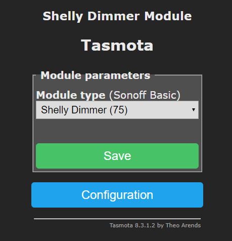
Is this how it's supposed to look like?? I can't change the button type without making a custom preset/template...
D0n1elT
on 27 May 2020
And I have a question:
I think you are looking for "Configure Template"
There you switched to "75" and activate Template in "Configurate Other"
Then you had this:
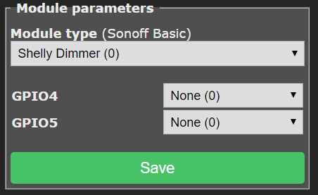
from that:
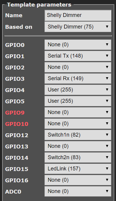
poweronstate3 only work if fade is on. Also in v0.4
The off switching, I figured out comes from to mouch pressure on the module.
If I play around with the modul under load, I had same issue.
If the modul is installd without any pressure, everything work.
BassT23
on 27 May 2020
Found another issue:
Emulation with Belkin WeMo (single device) - work
Emulation with Hue Bridge (multi device) - don´t work - can´t find the device with Alexa
Only as multi device, the dimmer slider can be used with Alexa.
BassT23
on 27 May 2020
Thanks @BassT23 and @D0n1elT for all the testing your doing!!
Is this how it's supposed to look like?? I can't change the button type without making a custom preset/template...
I haven't set any of the pins to be GPIO_USER pins, hence there is nothing on this list. I'm not sure how much customisation can be done with this HW. Which pins would you like to be configurable and in which way?
The off switching, I figured out comes from to mouch pressure on the module.
I've not tested my Shelly Dimmer with more than 12W bulb so I will try with something a bit more powerful next.
00:00:00 SHD: MCU v2.26, Brightness:0(0%), Power:0, Fade:0
I also noticed both of you have the more up-to-date firmware in the co-processor v2.26 where as I am still using the old v1.3 firmware so I'm wondering if there is a difference there also...
Found another issue:
Emulation with Belkin WeMo (single device) - work
Emulation with Hue Bridge (multi device) - don´t work - can´t find the device with Alexa
I've never played around with the emulation but I will try that tonight!
jamesturton
on 27 May 2020
The off switching, I figured out comes from to mouch pressure on the module.
I've not tested my Shelly Dimmer with more than 12W bulb so I will try with something a bit more powerful next.
I seem that with a 9W bulb. And I don´t think thats a software problem. I mean HW pressure on the module. The module seems like a little bitchy ;) or some solder joits are too small and go away under pressure and load, ...
BassT23
on 27 May 2020
@jamesturton
Just dropping by to say thank you for the work you’ve done on the Shelly Dimmer.
I can’t help currently with testing, but I just wanted you to know that I really appreciate your work on this issue. Please keep up the good work :)
 maciejtarmas
on 27 May 2020
maciejtarmas
on 27 May 2020
I haven't set any of the pins to be
GPIO_USERpins, hence there is nothing on this list. I'm not sure how much customisation can be done with this HW. Which pins would you like to be configurable and in which way?2x 230v inputs are present on the module and you can use whatever you want switches, buttons, inverted buttons and nverted switches and so on... And for shelly 1 for example you can use whatever you have in your current house installation
D0n1elT
on 27 May 2020
Nice work James!
After your corrections to my code and backporting your revision to esphome
I now have firmware updates working. I've committed the code to my repo..
Op wo 27 mei 2020 om 19:01 schreef James Turton notifications@github.com:
Thanks @BassT23 https://github.com/BassT23 and @D0n1elT
https://github.com/D0n1elT for all the testing your doing!!Is this how it's supposed to look like?? I can't change the button type
without making a custom preset/template...I haven't set any of the pins to be GPIO_USER pins, hence there is
nothing on this list. I'm not sure how much customisation can be done with
this HW. Which pins would you like to be configurable and in which way?The off switching, I figured out comes from to mouch pressure on the
module.I've not tested my Shelly Dimmer with more than 12W bulb so I will try
with something a bit more powerful next.00:00:00 SHD: MCU v2.26, Brightness:0(0%), Power:0, Fade:0
I also noticed both of you have the more up-to-date firmware in the
co-processor v2.26 where as I am still using the old v1.3 firmware so I'm
wondering if there is a difference there also...Found another issue:
Emulation with Belkin WeMo (single device) - work
Emulation with Hue Bridge (multi device) - don´t work - can´t find the
device with AlexaI've never played around with the emulation but I will try that tonight!
—
You are receiving this because you were mentioned.
Reply to this email directly, view it on GitHub
https://github.com/arendst/Tasmota/issues/6914#issuecomment-634803943,
or unsubscribe
https://github.com/notifications/unsubscribe-auth/AAENFF3HOAGM2LX3CCOPIVDRTVBPJANCNFSM4JMCVWCA
.
wichers
on 27 May 2020
Nice work James! After your corrections to my code and backporting your revision to esphome I now have firmware updates working. I've committed the code to my repo..
Amazing @wichers! I shall work on getting this working with Tasmota!
jamesturton
on 27 May 2020
I have now integrated the stm32flash module in my Tasmota code and it seems to be working good.
The only problem is it seems the filesize of the binary is now too big to flash OTA...
2x 230v inputs are present on the module and you can use whatever you want switches, buttons, inverted buttons and nverted switches and so on... And for shelly 1 for example you can use whatever you have in your current house installation
@D0n1elT I have made both input pins GPIO_USER pins so they should show up in the 'Module parameters' list now.
jamesturton
on 28 May 2020
So I guess I should recap what still needs to be done before I submit a PR:
- [x] Optimise filesize to be OTA updatable
- [ ] Check power measurement calibration
- [x] Rising / falling edge switching
jamesturton
on 28 May 2020
The only problem is it seems the filesize of the binary is now too big to
flash OTA...
How come? Don't know how the ota procedure works but the flash on the
dimmer is 2M in size.. The original mongoose-os binaries are over 800Kb,
and OTA still works?
Op do 28 mei 2020 om 23:22 schreef James Turton notifications@github.com:
I have now integrated the stm32flash module in my Tasmota code and it
seems to be working good.
The only problem is it seems the filesize of the binary is now too big to
flash OTA...2x 230v inputs are present on the module and you can use whatever you want
switches, buttons, inverted buttons and nverted switches and so on... And
for shelly 1 for example you can use whatever you have in your current
house installation@D0n1elT https://github.com/D0n1elT I have made both input pins
GPIO_USER pins so they should show up in the 'Module parameters' list now.tasmota_shelly_dimmer_v0.5.zip
https://github.com/arendst/Tasmota/files/4698323/tasmota_shelly_dimmer_v0.5.zip—
You are receiving this because you were mentioned.
Reply to this email directly, view it on GitHub
https://github.com/arendst/Tasmota/issues/6914#issuecomment-635615025,
or unsubscribe
https://github.com/notifications/unsubscribe-auth/AAENFFZ2YBLYIYG2YSHFGKLRT3IYRANCNFSM4JMCVWCA
.
wichers
on 29 May 2020
Ok, did some more reading. Didn't know the ESP8266 can only map 1MB of
flash to memory, unless a special boot loader is used the size limitation
of 1MB remains..
Op do 28 mei 2020 om 23:50 schreef James Turton notifications@github.com:
So I guess I should recap what still needs to be done before I submit a PR:
- Optimise filesize to be OTA updatable
- Check power measurement calibration
- Rising / falling edge switching
—
You are receiving this because you were mentioned.
Reply to this email directly, view it on GitHub
https://github.com/arendst/Tasmota/issues/6914#issuecomment-635627309,
or unsubscribe
https://github.com/notifications/unsubscribe-auth/AAENFF5ELWLZNVU2CX5DFH3RT3MEDANCNFSM4JMCVWCA
.
wichers
on 29 May 2020
Looks like I was building against an older arduino-core version. Updating to core 2.7.1 and compressing the binary file with gzip now allows me to update OTA. So it's the .gz file that should be uploaded to the Shelly Dimmer, _without_ extracting it.
Next onto rising / falling edge switching...
jamesturton
on 30 May 2020
Great work on the driver. Thank you!
The native firmware has a 'calibrate' feature. I am not actually sure what it does but will Tasmota need something equivalent? I suspect the brightness level is not always linear with a simple 0-100% It also seems to be problematic for many LED luminaires to initially power them at low brightness. They need a bit of a kickstart and then dimmed down to a minimum brightness.
rbswift
on 30 May 2020
do you have the possibility to create an arduino sketch to use with shelly dimmer? can you help me? I wanted to ask you otherwise if you have a tasmota sketch to use.?
claudiovillani58
on 30 May 2020
The native firmware has a 'calibrate' feature. I am not actually sure what it does but will Tasmota need something equivalent?
@rbswift Tasmota currently has support for power calibration, where the calibration is stored in the ESP. It _looks_ like the Shelly Dimmer stores the calibration in the STM instead.
What I think I will do, unless anyone else has a better idea, is to send the clear calibration command to the STM and then use the power calibration in Tasmota.
I suspect the brightness level is not always linear with a simple 0-100%
Maybe checkout the LedTable setting?
It also seems to be problematic for many LED luminaires to initially power them at low brightness. They need a bit of a kickstart and then dimmed down to a minimum brightness.
Yes! You are not the only one who has been having that problem it seems: https://www.facebook.com/groups/ShellyIoTCommunitySupport/permalink/2828022090630470/
From the post:
Dimmer Warm-up feaure added, device can send wake-up impulse controled by time and power to the bulb when brightness is low.
I will try the 1.7.0 STM firmware with this Tasmota driver and see how it goes.
jamesturton
on 1 Jun 2020
I just noticed that with the original Shelly firmware my Led transformer doesn't make a sound, but with Tasmota 0.5 it is buzzing. Any ideas? Tried to put it in a video, but unfortunately you can't hear it in the video.
Unfortunately I can't get it to flash the .gz file of version 0.6 via OTA either. What am I doing wrong?
 cinemarene
on 2 Jun 2020
cinemarene
on 2 Jun 2020
I just noticed that with the original Shelly firmware my Led transformer doesn't make a sound, but with Tasmota 0.5 it is buzzing. Any ideas? Tried to put it in a video, but unfortunately you can't hear it in the video.
@cinemarene I believe this is due to the pulse mode used (either leading edge or trailing edge). The next version of the driver should (hopefully) fix this issue.
jamesturton
on 2 Jun 2020
@cinemarene
Unfortunately I can't get it to flash the .gz file of version 0.6 via OTA either. What am I doing wrong?
Did you try to flash minimal.bin at first? (To make space)
For me it work
BassT23
on 2 Jun 2020
@BassT23
Did you try to flash minimal.bin at first? (To make space)
For me it work
Yes, i tried different versions. Message show always "Upload buffer miscompare". I also searched for this message and tried differend steps to fix it, but nothing works. I think the only sollution is to flash it directly.
cinemarene
on 2 Jun 2020
So here is the next version of the Shelly Dimmer driver!
tasmota_shelly_dimmer_v0.7.bin.gz
This version implements leading / trailing edge dimming using the command ShdLeadingEdge. ShdLeadingEdge 1 will set to leading edge dimming and ShdLeadingEdge 0 will set it to trailing edge dimming.
I have also implemented 'warm up' which adds two command ShdWarmupBrightness and ShdWarmupTime. ShdWarmupBrightness x where x is the wakeup pulse brightness in % between 10% and 100%. ShdWarmupTime x is the wakeup pulse duration in ms between 20ms and 200ms.
I would appreciate people who have had problems testing these new settings and reporting back!
jamesturton
on 2 Jun 2020
I also have now the problem with "Upload buffer miscompare"
I´m on v0.6
tryed to flash the minimal.bin, and also the 0.7.gz, brings the failure.
What could I do?
BassT23
on 3 Jun 2020
With version 0.7 the buzzing has become much less. Thank 4 that.
But like Version 0.6 the message "Upload buffer miscompare" appears and i had to flash it directly.
Leading / trailing edge dimming works but i have to restart the device first when i change the ShdLeadingEdge setting, otherwise when i change the dimm level, it double blinks.
ShdWarmupBrightness works, but I cannot turn it off once it is enabled.
cinemarene
on 3 Jun 2020
I also have now the problem with "Upload buffer miscompare"
I´m on v0.6
tryed to flash the minimal.bin, and also the 0.7.gz, brings the failure.What could I do?
@BassT23 Could you try tasmota-minimal.bin.gz
Leading / trailing edge dimming works but i have to restart the device first when i change the ShdLeadingEdge setting, otherwise when i change the dimm level, it double blinks.
@cinemarene It sounds like perhaps you have the warmup values too high. Perhaps change them to the minimum values of ShdWarmupBrightness 10 and ShdWarmupTime 20.
jamesturton
on 3 Jun 2020
@jamesturton minimal.bin.gz work!
BassT23
on 3 Jun 2020
Disassembled the esp8266 1.6 dimmer in IDA (see attachments). Trying to
extract the calibration algorithm, but it's a lot to digest..
wichers
on 3 Jun 2020
I would guess, that the calibration feature is using the power measurement combined with a dimming from 0-100%.
Knowing how much energy is used while slowly dimming up you can approximate the dimming curve of the lamp and map that to the linear "new" 0-100%.
E.g. a small LED lamp using the uncalibrated 0-100% only does a visual (/power consumption) change (and non linear!) from 1-15%. After calibration that is mapped more or less to the new 0-100% and allows much more granular control. And looks linear for the human eyes in brightness increase while sliding up.
mgoeller
on 7 Jun 2020
v0.7:
My lamp still turns off after 4 seconds....
If I use
ShdLeadingEdge 1the humming is much less.My Shelly resets itself after about 2 minutes and I must connect to it via a new wifi network...
Steps to reproduce:- Use v0.7 (It wasn't a problem before)
- Setup Home Wifi via
tasmota_xxxxxnetwork - Configure web log level
4 more debug - Configure Module
Shelly Dimmer (75) - After restart configure both inputs to
Button1 - Enter command
ShdLeadingEdge 1 - Wait
- It resets and the whole procedure loops.... :c
(Note it is a new configuration so no mqtt connected and I didn't click any buttons after entering theshdleadingedge 1command..)
D0n1elT
on 7 Jun 2020
Thanks to all of you for testing!
@mgoeller Your theory for the calibration to 'linearise' the power curve seems to make perfect sense! I guess the 0x30 and 0x31 packets describe a lookup table for this linearisation. As this calibration procedure would improve the experience had by most people I think it's an important thing to sort out before PR so I will try working hard this week to sort it out!
@D0n1elT I will try replicating your error and report back!
jamesturton
on 8 Jun 2020
@mgoeller https://github.com/mgoeller Your theory for the calibration to
'linearise' the power curve seems to make perfect sense
Agree although to me the 2 pairs of shorts don't make sense just yet, and
so does the 2000 value at the end of the curve..
Op ma 8 jun. 2020 om 08:19 schreef James Turton notifications@github.com:
Thanks to all of you for testing!
@mgoeller https://github.com/mgoeller Your theory for the calibration
to 'linearise' the power curve seems to make perfect sense! I guess the
0x30 and 0x31 packets describe a lookup table for this linearisation. As
this calibration procedure would improve the experience had by most people
I think it's an important thing to sort out before PR so I will try working
hard this week to sort it out!@D0n1elT https://github.com/D0n1elT I will try replicating your error
and report back!—
You are receiving this because you were mentioned.
Reply to this email directly, view it on GitHub
https://github.com/arendst/Tasmota/issues/6914#issuecomment-640393585,
or unsubscribe
https://github.com/notifications/unsubscribe-auth/AAENFFZ4HUDCGZ2BIEGRQDDRVR7IBANCNFSM4JMCVWCA
.
wichers
on 8 Jun 2020
@D0n1elT I have managed to duplicate the problem you have found following your steps and think I have found the error (and the solution!).
The input on the Shelly Dimmer are lowside and therefor the logic must be inverted.
When setting the inputs to Button1 the inputs are not inverted and therefore the button is 'active' when it's not pressed - invoking a factory reset.
You should set the button type to Button1i (or Button2i...) to be inverted lowside inputs.
Hope this helps!
jamesturton
on 8 Jun 2020
Maybe set Button1i and Button2i as standards? If there not physically connected then it doesn't matter whats set in Tasmota and when someone has a switch connected instead of a button for example, he can see directly that the shelly dimmer has inverted inputs and set his settings accordingly..
Thank you for investigating! I didn't had the time for investigating :)
D0n1elT
on 8 Jun 2020
Ok! I shall change the default pin configurations back to GPIO_SWT1_NP and GPIO_SWT2_NP. This will of course still be changeable with a custom template.
jamesturton
on 8 Jun 2020
I just received some Shelly 2 Dimmers and wonder if this FW is/will be compatible? How can I help?
Thanks for the work!
 jeremybdk
on 21 Jun 2020
jeremybdk
on 21 Jun 2020
@jeremybdk nice! The best thing you could do right now would be to open up the unit and take some high quality photos of both the top and the bottom of the board so we can see how similar the circuit is. That we we can make a guess as to if the current FW is compatible. Maybe I should order myself a Shelly Dimmer 2 :)
jamesturton
on 21 Jun 2020
For everyone else interested in the progress of this driver, I have been looking into the calibration routine used in the Shelly firmware and it seems @mgoeller was correct with his idea of 'linearisation' of the power curve. I made some measurements of power at different brightness levels using the Shelly stock firmware after calibration and with the new Tasmota driver.
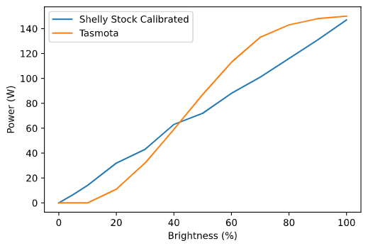
As you can see, the Shelly stock curve is much more linear. Unless anyone else has any more ideas about how to decode the calibration protocol used then I think I am tempted to issue a pull request for the driver in the current state without calibration. A new 'software' calibration routine could perhaps be implemented in Tasmota, but then this would be outside the scope of this driver.
As a final note I am considering the file size of the system made when building with this Shelly Dimmer driver. My thoughts are as following:
- Include the firmware update file by default. This makes updating the unit OTA a bit more hassle due to the increased size, but will ensure the correct FW version on the ST co-processor. A separate dedicated binary build would be required for this.
- Add the firmware update file as a compile time option but include the Shelly driver as default. If updates to the driver would be needed then updating the unit OTA would be easy, but if someone is using a unit which the co-processor has an old (or newer) system then it may not work as expected.
- Downloading ST firmware from the internet if it needs to be updated. Does anyone know if this is possible?
- Making our own ST firmware which implements the bare-bones of what is required to reduce code size as far as possible. This would also give us better control as to what is going on in the co-processor!
Any thoughts on the above would be greatly appreciated!
jamesturton
on 21 Jun 2020
Give me some more time, and that calibration routine is sorted. I'm not that far off, see below..
Downloading ST firmware from the internet if it needs to be updated. Does anyone know if this is possible?
The link to the firmware downloads is up in this thread somewhere. I use the mongoose OS esptool2 to extract stm.bin from that spiffs image
Making our own ST firmware which implements the bare-bones of what is required to reduce code size as far as possible. This would also give us better control as to what is going on in the co-processor!
Sounds like too much work.. Current shelly ST firmware is getting stable already, isn't it?
Cheers, Alexander
struct dimmer_ctx {
uint32_t field_0;
uint16_t field_4;
uint16_t field_6;
uint16_t field_8;
uint16_t field_A;
float field_C;
float field_10;
float field_14;
float field_18;
FILE *field_1C;
}
void calibrate_dimmer(void *arg)
{
//.irom:40277190 9A 99 99 3E dword_40277190 .int 0x3E99999A ; DATA XREF: dimmer_calibrate+184↓r
//.irom:40277190 ; dimmer_calibrate+18D↓r
//.irom:40277198 51 E8 FE 3F byte_3FFEE851 .int 0x3FFEE851 ; DATA XREF: dimmer_calibrate+85↓r
uint8_t byte_3FFEE851;
//.irom:4027719C 54 E8 FE 3F dimmer_ctx .int unk_3FFEE854 ; DATA XREF: dimmer_calibrate+8B↓r
//.irom:402771A0 74 FD FE 3F dword_3FFEFD74 .int 0x3FFEFD74 ; DATA XREF: dimmer_calibrate+9F↓r
uint32_t *dword_3FFEFD74;
//.irom:402771A4 28 E8 FE 3F word_3FFEE828 .int unk_3FFEE828 ; DATA XREF: dimmer_calibrate+BB↓r
uint16_t word_3FFEE828;
//.irom:402771A8 46 E8 FE 3F word_3FFEE846 .int unk_3FFEE846 ; DATA XREF: dimmer_calibrate+D9↓r
uint16_t word_3FFEE846;
//.irom:40277194 48 E8 FE 3F word_3FFEE848 .int unk_3FFEE848 ; DATA XREF: dimmer_calibrate+11↓r
uint16_t word_3FFEE848;
//.irom:402771AC 44 E8 FE 3F word_3FFEE844 .int unk_3FFEE844 ; DATA XREF: dimmer_calibrate+114↓r
uint16_t word_3FFEE844;
//.irom:402771B0 7B 14 AE 47 dword_402771B0 .int 0x47AE147B ; DATA XREF: dimmer_calibrate+140↓r
//.irom:402771B0 ; sub_40286354+BE↓r ...
//.irom:402771B4 E1 7A 84 3F dword_402771B4 .int 0x3F847AE1 ; DATA XREF: dimmer_calibrate+143↓r
uint32_t dword_402771B4;
//.irom:402771B4 ; sub_4027DCF4+6B↓r ...
//.irom:402771B8 00 00 80 3F dword_402771B8 .int 0x3F800000 ; DATA XREF: dimmer_calibrate+158↓r
FILE* file_3F800000;
//.irom:402771BC 00 00 C8 42 dword_402771BC .int 0x42C80000 ; DATA XREF: dimmer_calibrate+179↓r
//.irom:402771C0 4C E8 FE 3F dword_3FFEE84C .int unk_3FFEE84C ; DATA XREF: dimmer_calibrate+1D4↓r
uint32_t dword_3FFEE84C;
//.irom:402771C0 ; dimmer_calibrate+2F7↓r ...
//.irom:402771C4 17 B3 20 40 off_402771C4 .int aTable1Csv ; DATA XREF: dimmer_calibrate+1DA↓r
//.irom:402771C4 ; dimmer_remove_calibration_tables+1A↓r
//.irom:402771C4 ; "table1.csv"
//.irom:402771C8 22 B3 20 40 off_402771C8 .int aW ; DATA XREF: dimmer_calibrate+1DD↓r
//.irom:402771C8 ; dimmer_calibrate+417↓r ...
//.irom:402771C8 ; "w+"
//.irom:402771CC 25 B3 20 40 off_402771CC .int aD2f ; DATA XREF: dimmer_calibrate+2A1↓r
//.irom:402771CC ; "%d, %.2f\n"
//.irom:402771D0 50 E8 FE 3F byte_3FFEE850 .int unk_3FFEE850 ; DATA XREF: dimmer_calibrate:loc_40277560↓r
uint8_t byte_3FFEE850;
//.irom:402771D0 ; dimmer_calibrate+388↓r ...
//.irom:402771D4 98 E6 FE 3F dimmer_calib_0x30 .int 0x3FFEE698 ; DATA XREF: dimmer_calibrate+3AC↓r
//.irom:402771D4 ; dimmer_calibrate+42C↓r ...
//.irom:402771D8 00 00 7A 44 dword_402771D8 .int 0x447A0000 ; DATA XREF: dimmer_calibrate:loc_402775C1↓r
//.irom:402771DC 90 E6 FE 3F dword_402771DC .int 0x3FFEE690 ; DATA XREF: dimmer_calibrate+3F2↓r
//.irom:402771DC ; dimmer_calibrate+423↓r ...
//.irom:402771E0 2F B3 20 40 off_402771E0 .int aTable2Csv ; DATA XREF: dimmer_calibrate:loc_40277620↓r
//.irom:402771E0 ; dimmer_remove_calibration_tables+20↓r
//.irom:402771E0 ; "table2.csv"
//.irom:402771E4 3A B3 20 40 off_402771E4 .int aDD ; DATA XREF: dimmer_calibrate+42F↓r
//.irom:402771E4 ; "%d, %d\n"
//.irom:402771E8 10 B3 20 40 off_402771E8 .int aCalib0 ; DATA XREF: dimmer_calibrate+47A↓r
//.irom:402771E8 ; dimmer_calibration_write+16↓r ...
//.irom:402771E8 ; "calib0"
//.irom:402771EC 11 77 AA 55 dword_402771EC .int 0x55AA7711 ; DATA XREF: dimmer_calibrate+48C↓r
//.irom:402771F0 40 E8 FE 3F off_402771F0 .int unk_3FFEE840 ; DATA XREF: dimmer_calibrate+4CD↓r
//.irom:402771F0 ; dimmer_calibrate+4DC↓r ...
//.irom:402771F4 B0 E8 FE 3F off_402771F4 .int unk_3FFEE8B0 ; DATA XREF: dimmer_calibrate:loc_402776ED↓r
//.irom:402771F4 ; sub_402779B0:loc_402779C9↓r ...
//.irom:402771F8 40 00 00 00 dword_402771F8 .int 0x40 ; DATA XREF: dimmer_calibrate+4F3↓r
//.irom:402771F8 ; sub_40278F70+47↓r ...
//.irom:402771FC FC CD 00 40 __extendsfdf2 .int 0x4000CDFC ; DATA XREF: dimmer_calibrate+13A↓r
//.irom:402771FC ; dimmer_calibrate+295↓r ...
//.irom:40277200 5C CD 00 40 __truncdfsf2 .int 0x4000CD5C ; DATA XREF: dimmer_calibrate+14C↓r
//.irom:40277200 ; .irom:4027E509↓r ...
//.irom:40277204 4C 0D 10 40 __lesf2 .int __lesf2_0 ; DATA XREF: dimmer_calibrate+157↓r
//.irom:40277208 B8 0D 10 40 __ltsf2 .int __ltsf2_0 ; DATA XREF: dimmer_calibrate+183↓r
//.irom:40277208 ; .irom:4027E73E↓r ...
//.irom:4027720C 98 0D 10 40 __gesf2 .int __gesf2_0 ; DATA XREF: dimmer_calibrate+269↓r
//.irom:4027720C ; dimmer_calibrate+317↓r ...
// addi , a1, a1, 0xD0
// s32i.n , a0, a1, 0x2C
// s32i.n , a12, a1, 0x28
// s32i.n , a13, a1, 0x24
// s32i.n , a14, a1, 0x20
// s32i.n , a15, a1, 0x1C
// l32r , a2, word_3FFEE848
// l16ui , a2, a2, 0
//word_3FFEE848 = 0;
// movi , a3, 0x126
// bne , a2, a3, loc_4027722C
// j , loc_4027732F
if (word_3FFEE848 != 0x126)
goto loc_4027722C;
goto loc_4027732F;
loc_4027722C:
// bltu , a3, a2, loc_40277258
// movi , a3, 0x121
// bne , a2, a3, loc_40277238
// j , loc_402772D9
if (word_3FFEE848 < 0x126)
goto loc_40277258;
if (word_3FFEE848 != 0x121)
goto loc_40277238;
goto loc_402772D9;
loc_40277238:
// bltu , a3, a2, loc_40277241
// beqz , a2, loc_4027728E
// j , loc_40277708
if (word_3FFEE848 < 0x121)
goto loc_40277241;
if (word_3FFEE848 == 0)
goto loc_4027728E;
goto loc_40277708;
loc_40277241:
// movi , a3, 0x123
// bne , a2, a3, loc_4027724A
// j , loc_402772F4
if (word_3FFEE848 != 0x123)
goto loc_4027724A;
goto loc_402772F4;
loc_4027724A:
// movi , a3, 0x124
// bne , a2, a3, loc_40277253
// j , loc_40277315
if (word_3FFEE848 != 0x124)
goto loc_40277253;
goto loc_40277315;
loc_40277253:
// j , loc_40277708
goto loc_40277708;
loc_40277258:
// movi , a3, 0x140
// bne , a2, a3, loc_40277261
// j , loc_4027740D
if (word_3FFEE848 != 0x140)
goto loc_40277261;
goto loc_4027740D;
loc_40277261:
// bltu , a3, a2, loc_40277279
// movi , a3, 0x136
// bne , a2, a3, loc_4027726D
// j , loc_402773B5
if (word_3FFEE848 < 0x140)
goto loc_40277279;
if (word_3FFEE848 != 0x136)
goto loc_4027726D;
goto loc_402773B5;
loc_4027726D:
// movi , a3, 0x137
// bne , a2, a3, loc_40277276
// j , loc_402773D5
if (word_3FFEE848 != 0x137)
goto loc_40277276;
goto loc_402773D5;
loc_40277276:
// j , loc_40277708
goto loc_40277708;
loc_40277279:
// movi , a3, 0x142
// bne , a2, a3, loc_40277282
// j , loc_40277434
if (word_3FFEE848 != 0x142)
goto loc_40277282;
goto loc_40277434;
loc_40277282:
// movi , a3, 0x146
// bne , a2, a3, loc_4027728B
// j , loc_40277451
if (word_3FFEE848 != 0x146)
goto loc_4027728B;
goto loc_40277451;
loc_4027728B:
// j , loc_40277708
goto loc_40277708;
loc_4027728E:
// movi , a3, 1
// l32r , a2, byte_3FFEE851
// s8i , a3, a2, 0
byte_3FFEE851 = 1;
// l32r , a2, dimmer_ctx
// movi.n , a3, 0
// s16i , a3, a2, 4
// s16i , a3, a2, 6
// s16i , a3, a2, 8
dimmer_ctx.field_4 = 0;
dimmer_ctx.field_6 = 0;
dimmer_ctx.field_8 = 0;
// movi , a2, 800
// call0 , malloc
// l32r , a3, dword_3FFEFD74
// s32i.n , a2, a3, 0
// beqz , a2, loc_4027766C
// movi , a3, 0
// movi , a4, 800
// l32r , a0, memset
// callx0 , a0
dword_3FFEFD74 = (uint8_t *) malloc(800);
if (dword_3FFEFD74 == 0)
goto loc_4027766C;
memset(dword_3FFEFD74, 0, 800);
// movi.n , a2, 0
// movi , a3, 200
// call0 , gpio_something
gpio_something(0, 200);
// l32r , a2, word_3FFEE828
// movi , a3, 500
// call0 , timer_poll_init
timer_poll_init(word_3FFEE828, 500);
// movi , a3, 0x121
// l32r , a2, word_3FFEE848
// s16i , a3, a2, 0
word_3FFEE848 = 0x121;
loc_402772D9:
// l32r , a2, word_3FFEE828
// call0 , timer_poll_is_due
// beqz , a2, loc_40277710
if (timer_poll_is_due(word_3FFEE828) == 0)
goto loc_40277710;
// movi , a3, 0
// l32r , a2, word_3FFEE846
// s16i , a3, a2, 0
word_3FFEE846 = 0;
// movi , a3, 0x123
// l32r , a2, word_3FFEE848
// s16i , a3, a2, 0
word_3FFEE848 = 0x123;
loc_402772F4:
// l32r , a2, word_3FFEE846
// movi , a3, 0x3E8
// call0 , dimmer_send_4_command
// bgei , a2, 2, loc_40277303
// j , loc_40277710
if (dimmer_send_4_command(word_3FFEE846, 0x3E8) >= 2)
goto loc_40277303;
goto loc_40277710;
loc_40277303:
// l32r , a2, word_3FFEE828
// l32r , a3, dword_40277074
// call0 , timer_poll_init
timer_poll_init(word_3FFEE828, 5000);
// movi , a3, 0x124
// l32r , a2, word_3FFEE848
// s16i , a3, a2, 0
word_3FFEE848 = 0x124;
//
loc_40277315:
// l32r , a2, word_3FFEE828
// call0 , timer_poll_is_due
// beqz , a2, loc_40277710
if (timer_poll_is_due(word_3FFEE828) == 0)
goto loc_40277710;
// movi.n , a3, 0
// l32r , a2, word_3FFEE844
// s16i , a3, a2, 0
word_3FFEE844 = 0;
// movi , a3, 0x126
// l32r , a2, word_3FFEE848
// s16i , a3, a2, 0
word_3FFEE848 = 0x126;
loc_4027732F:
// l32r , a2, word_3FFEE844
// movi.n , a3, 0x10
// call0 , dimmer_send_poll_command
// bgei , a2, 2, loc_4027733D
// j , loc_40277710
if (dimmer_send_poll_command(word_3FFEE844 , 0x10) >= 2)
goto loc_4027733D;
goto loc_40277710;
loc_4027733D:
// l32r , a13, dimmer_ctx
// l32i.n , a12, a13, 0x14
// s32i.n , a12, a13, 0xC
dimmer_ctx.field_C = dimmer_ctx.field_14;
// mov.n , a2, a12
// l32r , a0, __extendsfdf2
// callx0 , a0
// l32r , a4, dword_402771B0
// l32r , a5, dword_402771B4
// l32r , a0, __muldf3
// callx0 , a0
// l32r , a0, __truncdfsf2
// callx0 , a0
// s32i , a2, a13, 0x18
dimmer_ctx.field_18 = (float) dimmer_ctx.field_14 * 1.99915927897371165363347075707E37;
// mov , a2, a12
// l32r , a3, dword_402771B8 ; 1.0f
// l32r , a0, __lesf2 // Return 0 iff a == b, 1 iff a > b, 2 iff a ? b, -1 iff a < b
// callx0 , a0
// bgei , a2, 1, loc_40277379
if (dimmer_ctx.field_14 > 1.0f)
goto loc_40277379;
// movi , a3, 0
// l32r , a2, byte_3FFEE851
// s8i , a3, a2, 0
byte_3FFEE851 = 0;
loc_40277379:
// l32r , a2, byte_3FFEE851
// l8ui , a2, a2, 0
// beqz , a2, loc_40277657
if (byte_3FFEE851 == 0)
goto loc_40277657;
// mov , a2, a12
// l32r , a3, dword_402771BC
// l32r , a0, __divsf3_0
// callx0 , a0
// mov.n , a12, a2
// l32r , a3, dword_40277190 // 0.300000011921
// l32r , a0, __ltsf2 // Return 0 iff a == b, 1 iff a > b, 2 iff a ? b, -1 iff a < b
// callx0 , a0
// l32r , a3, dword_40277190
// movltz , a12, a3, a2
// l32r , a2, dimmer_ctx
// s32i.n , a12, a2, 0x10
if (dimmer_ctx.field_14 / 100.0 < 0.300000011921)
dimmer_ctx.field_10 = 0.300000011921;
// movi.n , a3, 0
// l32r , a2, word_3FFEE846
// s16i , a3, a2, 0
word_3FFEE846 = 0;
// movi , a3, 0x136
// l32r , a2, word_3FFEE848
// s16i , a3, a2, 0
word_3FFEE848 = 0x136;
loc_402773B5:
// l32r , a2, word_3FFEE846
// movi.n , a3, 0
// call0 , dimmer_send_4_command
// bgei , a2, 2, loc_402773C3
// j , loc_40277710
if (dimmer_send_4_command(dword_3FFEE846, 0) >= 2)
goto loc_402773C3;
goto loc_40277710;
loc_402773C3:
// l32r , a2, word_3FFEE828
// l32r , a3, dword_40277074
// call0 , timer_poll_init
timer_poll_init(word_3FFEE828, 5000);
// movi , a3, 0x137
// l32r , a2, word_3FFEE848
// s16i , a3, a2, 0
//
word_3FFEE848 = 0x137;
loc_402773D5:
// l32r , a2, word_3FFEE828
// call0 , timer_poll_is_due
// beqz , a2, loc_40277710
if (timer_poll_is_due(word_3FFEE828) == 0)
goto loc_40277710;
// movi.n , a3, 0
// l32r , a2, dword_3FFEE84C
// s32i , a3, a2, 0
dword_3FFEE84C = 0;
// l32r , a2, off_402771C4 ; "table1.csv"
// l32r , a3, off_402771C8 ; "w+"
// call0 , fopen
// l32r , a3, dimmer_ctx
// s32i , a2, a3, 0x1C
// bnez , a2, loc_40277569
// j , loc_40277583
dimmer_ctx.field_C = fopen("table1.csv", "w+")
if (dimmer_ctx.field_C == 0)
goto loc_40277569;
goto loc_40277583;
loc_402773FC:
// movi.n , a3, 0
// l32r , a2, word_3FFEE846
// s16i , a3, a2, 0
word_3FFEE846 = 0;
// movi , a3, 0x140
// l32r , a2, word_3FFEE848
// s16i , a3, a2, 0
word_3FFEE848 = 0x140;
loc_4027740D:
// l32r , a2, word_3FFEE846
// l32r , a3, dimmer_ctx
// l16ui , a3, a3, 6
// call0 , dimmer_send_4_command
// bgei , a2, 2, loc_4027741F
// j , loc_40277710
if (dimmer_send_4_command(word_3FFEE846, dimmer_ctx.field_6) >= 2)
goto loc_4027741F;
goto loc_40277710;
loc_4027741F:
// l32r , a2, word_3FFEE828
// movi , a3, 0x320
// mov , a1, a1
// call0 , timer_poll_init
timer_poll_init(word_3FFEE828, 0x320);
// movi , a3, 0x142
// l32r , a2, word_3FFEE848
// s16i , a3, a2, 0
word_3FFEE848 = 0x142;
loc_40277434:
// l32r , a2, word_3FFEE828
// mov , a1, a1
// call0 , timer_poll_is_due
// beqz , a2, loc_40277710
if (timer_poll_is_due(word_3FFEE828))
goto loc_40277710;
// movi.n , a3, 0
// l32r , a2, word_3FFEE844
// s16i , a3, a2, 0
word_3FFEE844 = 0;
// movi , a3, 0x146
// l32r , a2, word_3FFEE848
// s16i , a3, a2, 0
word_3FFEE848 = 0x146;
loc_40277451:
// l32r , a2, word_3FFEE844
// movi.n , a3, 8
// call0 , dimmer_send_poll_command
// bgei , a2, 2, loc_4027745F
// j , loc_40277710
if (dimmer_send_poll_command(word_3FFEE844 , 8) >= 2)
goto loc_4027745F;
goto loc_40277710;
loc_4027745F:
// l32r , a12, dimmer_ctx
// l16ui , a13, a12, 4
// mov.n , a2, a13
// l32r , a0, __floatsisf
// callx0 , a0
// l32i.n , a3, a12, 0x10
// l32r , a0, __mulsf3
// callx0 , a0
// mov.n , a3, a2
// l32i.n , a2, a12, 0x14
// l32r , a0, __gesf2 ; Return 0 iff a == b, 1 iff a > b, -2 iff a ? b, -1 iff a < b
// callx0 , a0
// bltz , a2, loc_402774BD
if (dimmer_ctx.field_14 < dimmer_ctx.field_4 * dimmer_ctx.field_10)
goto loc_402774BD;
// l16ui , a3, a12, 6
// l32r , a2, dword_3FFEFD74
// l32i.n , a4, a2, 0
// addx8 , a13, a13, a4
// s16i , a3, a13, 0
dword_3FFEFD74[dimmer_ctx.field_4 << 3] = dimmer_ctx.field_6;
// l32i.n , a3, a12, 0x14
// l16ui , a4, a12, 4
// l32i.n , a2, a2, 0
// addx8 , a2, a4, a2
// s32i.n , a3, a2, 4
dword_3FFEFD74[dimmer_ctx.field_4 << 3] = dimmer_ctx.field_14;
// l16ui , a13, a12, 6
// l32i.n , a2, a12, 0x14
// l32r , a0, __extendsfdf2
// callx0 , a0
// mov.n , a6, a2
// mov.n , a7, a3
// l32i.n , a2, a12, 0x1C ; B8
// l32r , a3, off_402771CC ; "%d, %.2f\n"
// mov.n , a4, a13
// call0 , fprintf
fprintf(dimmer_ctx.field_1C, "%d, %.2f\n", dimmer_ctx.field_6, dimmer_ctx.field_14);
// l16ui , a2, a12, 4
// addi.n , a2, a2, 1
// s16i , a2, a12, 4
dimmer_ctx.field_4 += 1;
loc_402774BD:
// l32r , a2, dimmer_ctx
// l16ui , a3, a2, 6
// addi.n , a3, a3, 5
// s16i , a3, a2, 6
dimmer_ctx.field_6 += 5;
// l32i.n , a14, a2, 0x14
// l32i.n , a15, a2, 0xC
// mov , a2, a14
// l32r , a0, __extendsfdf2
// callx0 , a0
// l32r , a4, dword_4025A7FC
// l32r , a5, dword_40275250
// l32r , a0, __muldf3
// callx0 , a0
// mov.n , a12, a2
// mov.n , a13, a3
// mov , a2, a15
// l32r , a0, __extendsfdf2
// callx0 , a0
// mov.n , a4, a2
// mov.n , a5, a3
// mov.n , a2, a12
// mov , a3, a13
// l32r , a0, __divdf3
// callx0 , a0
// l32r , a0, __fixdfsi
// callx0 , a0
// l32r , a3, dword_3FFEE84C
// l32i.n , a3, a3, 0
// bge , a3, a2, loc_40277511
// l32r , a3, dword_3FFEE84C
// s32i , a2, a3, 0
if (dword_3FFEE84C >= (dimmer_ctx.field_14 * 100.0f) / dimmer_ctx.field_C)
goto loc_40277511;
dword_3FFEE84C = (dimmer_ctx.field_14 * 100.0f) / dimmer_ctx.field_C;
loc_40277511:
// l32r , a2, dword_3FFEE84C
// l32i.n , a2, a2, 0
// movi , a3, 0x64
// bge , a3, a2, loc_40277522
if (0x64 >= dword_3FFEE84C)
goto loc_40277522;
// l32r , a2, dword_3FFEE84C
// s32i , a3, a2, 0
dword_3FFEE84C = 0;
loc_40277522:
// mov.n , a2, a14
// mov , a3, a15
// l32r , a0, __gesf2 ; Return 0 iff a == b, 1 iff a > b, -2 iff a ? b, -1 iff a < b / return a value greater than or equal to zero if neither argument is NaN, and a is greater than or equal to b.
// callx0 , a0
// bgez , a2, loc_40277578
if (dimmer_ctx.field_14 >= dimmer_ctx.field_C)
goto loc_40277578;
// mov.n , a2, a15
// l32r , a3, dimmer_ctx
// l32i , a3, a3, 0x18
// l32r , a0, __subsf3
// callx0 , a0
// mov.n , a3, a2
// mov , a2, a14
// l32r , a0, __gesf2
// callx0 , a0
// bltz , a2, loc_40277560
if (dimmer_ctx.field_14 >= dimmer_ctx.field_C - dimmer_ctx.field_18)
goto loc_40277560;
// l32r , a3, dimmer_ctx
// l16ui , a2, a3, 8
// addi.n , a2, a2, 1
// extui , a2, a2, 0, 16
// s16i , a2, a3, 8
dimmer_ctx.field_8 += 1;
// movi , a3, 9
// bltu , a3, a2, loc_40277578
if (9 < dimmer_ctx.field_8)
goto loc_40277578;
loc_40277560:
// l32r , a2, byte_3FFEE850
// l8ui , a2, a2, 0
// bnez , a2, loc_40277578
if (byte_3FFEE850 == 0)
goto loc_40277578;
loc_40277569:
// l32r , a2, dimmer_ctx
// l16ui , a2, a2, 4
// movi , a3, 0x63
// bltu , a3, a2, loc_40277578
// j , loc_402773FC
if (0x63 < dimmer_ctx.field_4)
goto loc_40277578;
goto loc_402773FC;
loc_40277578:
// l32r , a2, dimmer_ctx
// l32i.n , a2, a2, 0x1C
// call0 , fclose
fclose(dimmer_ctx.field_1C);
// j , loc_4027758B
goto loc_4027758B;
loc_40277583:
// movi.n , a3, 0
// l32r , a2, byte_3FFEE851
// s8i , a3, a2, 0
byte_3FFEE851 = 0;
loc_4027758B:
// l32r , a2, byte_3FFEE851
// l8ui , a2, a2, 0
// beqz , a2, loc_40277657
if (byte_3FFEE851 == 0)
goto loc_40277657;
// l32r , a2, byte_3FFEE850
// l8ui , a2, a2, 0
// bnez , a2, loc_40277657
if (byte_3FFEE850 == 0)
goto loc_40277657;
// movi , a3, 0x64
// l32r , a2, dword_3FFEE84C
// s32i.n , a3, a2, 0
dword_3FFEE84C = 0x64;
// l32r , a2, dimmer_ctx
// l32i.n , a3, a2, 0xC
// s32i.n , a3, a1, 4
tmp_0 = dimmer_ctx.field_C
// l16ui , a2, a2, 4
// s32i.n , a2, a1, 0
tmp_1 = dimmer_ctx.field_4
// mov.n , a15, a2
a15 = dimmer_ctx.field_4
// l32r , a2, dword_3FFEFD74
// l32i.n , a12, a2, 0
a12 = dword_3FFEFD74
// l32r , a13, dimmer_calib_0x30
a13 = dimmer_calib_0x30
// movi.n , a14, 0
a14 = 0
// j , loc_402775F3
goto loc_402775F3;
loc_402775C1:
// l32r , a2, dword_402771D8
// l32i , a3, a1, 4
// l32r , a0, __divsf3_0
// callx0 , a0
// l32i.n , a3, a12, 4
// l32r , a0, __mulsf3
// callx0 , a0
// l16ui , a3, a12, 0
dimmer_calib_0x30[0] = dword_3FFEFD74[0]
// s16i , a3, a13, 0
// l32r , a3, dword_4025A7FC
// l32r , a0, __addsf3
// callx0 , a0
// l32r , a0, __fixunssfsi
// callx0 , a0
// s16i , a2, a13, 2
dimmer_calib_0x30[1] = (uint16_t) 1000.0 / tmp_0 * dword_3FFEFD74[1] + 0;
// addi.n , a14, a14, 1
a14 += 1;
// addi.n , a12, a12, 8
a12 += 8;
// addi.n , a13, a13, 4
a13 += 4;
loc_402775F3:
// bge , a15, a14, loc_402775C1
if (dimmer_ctx.field_4 > a14)
goto loc_402775C1;
// movi , a2, 0x62
// l32i.n , a3, a1, 0
// bltu , a2, a3, loc_40277620
if (0x62 < tmp_1)
goto loc_40277620;
// l32r , a6, dword_402771DC
// addx4 , a6, a3, a6
a6 = a3 << 2 + dword_402771DC
// movi.n , a2, 0
a2 = 0
// movi , a5, 99
a5 = 99
// movi , a3, 2000
a3 = 2000
// j , loc_4027761D
goto loc_4027761D;
loc_40277611:
// add.n , a4, a6, a2
a4 = a6 + a2
// s16i , a3, a4, 8
[a4 + 8] = a3
// s16i , a3, a4, 0xA
[a4 + 10] = a3
// addi.n , a15, a15, 1
a15 += 1
// addi.n , a2, a2, 4
a2 += 4
loc_4027761D:
// bge , a5, a15, loc_40277611
if (a5 >= a15)
goto loc_40277611;
loc_40277620:
/**
* // l32r , a2, off_402771E0 ; "table2.csv"
* // l32r , a3, off_402771C8 ; "w+"
* // call0 , fopen
* // mov , a13, a2
* // beqz , a2, loc_40277657
* // l32r , a2, dword_402771DC
* // movi , a14, 0x198
* // add , a14, a14, a2
* // l32r , a12, dimmer_calib_0x30
* // l32r , a15, off_402771E4 ; "%d, %d\n"
* loc_4027763E:
* // mov , a2, a13
* // mov.n , a3, a15
* // l16ui , a4, a12, 0
* // l16ui , a5, a12, 2
* // call0 , fprintf
* // addi.n , a12, a12, 4
* // bne , a12, a14, loc_4027763E
* // mov , a2, a13
* // call0 , fclose
*/
loc_40277657:
// l32r , a2, dword_3FFEFD74
// l32i.n , a2, a2, 0
// beqz.n , a2, loc_40277674
// call0 , free
// movi.n , a3, 0
// l32r , a2, dword_3FFEFD74
// s32i.n , a3, a2, 0
// j , loc_40277674
if (dword_3FFEFD74 == 0)
goto loc_40277674;
free(dword_3FFEFD74);
dword_3FFEFD74 = 0;
goto loc_40277674;
loc_4027766C:
// movi.n , a3, 0
// l32r , a2, byte_3FFEE851
// s8i , a3, a2, 0
byte_3FFEE851 = 0;
loc_40277674:
// l32r , a2, byte_3FFEE851
// l8ui , a2, a2, 0
// beqz , a2, loc_402776CB
if (byte_3FFEE851 == 0)
goto loc_402776CB;
// l32r , a2, byte_3FFEE850
// l8ui , a2, a2, 0
// bnez , a2, loc_402776CB
if (byte_3FFEE850 == 0)
goto loc_402776CB;
/**
* // l32r , a2, off_402771E8 ; "calib0"
* // l32r , a3, off_402771C8 ; "w+"
* // call0 , fopen
* // mov , a12, a2
* // beqz , a2, loc_402776C8
* // l32r , a2, dword_402771DC
* // l32r , a3, dword_402771EC
* // s32i , a3, a2, 0
* // movi.n , a3, 0
* // s32i.n , a3, a2, 4
* // movi , a4, 0x190
* //
* loc_402776A5:
* // add , a5, a3, a2
* // l8ui , a6, a5, 8
* // l32i.n , a5, a2, 4
* // add.n , a5, a6, a5
* // s32i.n , a5, a2, 4
* // addi.n , a3, a3, 1
* // bne , a3, a4, loc_402776A5
* // l32r , a2, dword_402771DC
* // movi , a3, 0x198
* // movi.n , a4, 1
* // mov.n , a5, a12
* // call0 , fwrite
* // mov.n , a2, a12
* // call0 , fclose
*/
loc_402776C8:
// call0 , dimmer_send_calibration
loc_402776CB:
// movi.n , a2, 0
// l32r , a3, byte_3FFEE851
// s8i , a2, a3, 0
byte_3FFEE851 = 0;
// l32r , a3, byte_3FFEE850
// s8i , a2, a3, 0
byte_3FFEE850 = 0;
// l32r , a2, off_402771F0
// l32i.n , a2, a2, 0
// beqz.n , a2, loc_402776ED
// l32r , a0, mgos_clear_timer_0
// callx0 , a0
// movi.n , a3, 0
// l32r , a2, off_402771F0
// s32i.n , a3, a2, 0
loc_402776ED:
// l32r , a2, off_402771F4
// movi , a3, 0xA
// s32i , a3, a2, 4
// movi.n , a3, 1
// s32i.n , a3, a2, 0
// movi.n , a3, 0
// call0 , dimmer_send_switch_or_fade_command
// l32r , a2, dword_402771F8
// l32r , a3, dword_4025A7FC
// call0 , sub_40276E4C
loc_40277708:
// movi.n , a3, 0
// l32r , a2, word_3FFEE848
// s16i , a3, a2, 0
word_3FFEE848 = 0;
loc_40277710:
// l32i.n , a0, a1, 0x2C
// l32i.n , a12, a1, 0x28
// l32i.n , a13, a1, 0x24
// l32i.n , a14, a1, 0x20
// l32i.n , a15, a1, 0x1C
// addi , a1, a1, 0x30
// ret.n
return 0;
}
Give me some more time, and that calibration routine is sorted. I'm not that far off, see below..
That would be awesome @wichers! 😄
Downloading ST firmware from the internet if it needs to be updated. Does anyone know if this is possible?
The link to the firmware downloads is up in this thread somewhere. I use the mongoose OS esptool2 to extract stm.bin from that spiffs image
Thanks, I have found a link to the Shelly website where they host the firmware files but I was actually wondering if the ESP could download the firmware file into SPIFFS itself. We would have to extract the ST firmware first I guess. But maybe this is making too many assumptions to work well... Maybe lot's of people have their devices on VLANs which are isolated from the internet...
Making our own ST firmware which implements the bare-bones of what is required to reduce code size as far as possible. This would also give us better control as to what is going on in the co-processor!
Sounds like too much work.. Current shelly ST firmware is getting stable already, isn't it?
I would be happy to make a start with this if other people think it is the way to go. I've done quite a lot of development with the STM in the past. One advantage of this method would be returning extra information, such as voltage from the HLW8012.
Just a thought!
jamesturton
on 21 Jun 2020
Thanks, I have found a link to the Shelly website where they host the firmware files but I was actually wondering if the ESP could download the firmware file into SPIFFS itself.
Maybe Tasmota could get support for the 2MB SPI flash, current size limit is in the bootloader and OTA code.
wichers
on 21 Jun 2020
@jamesturton
I took these pictures with my iPhone. Hopefully they are good enough. If not let me know.
jeremybdk
on 21 Jun 2020
I noticed that a Shelly dev offered some help on an issue for the mongoose-homekit firmware for the dimmer. Did anyone try to contact them for help?
jeremybdk
on 22 Jun 2020
@jeremybdk These pics looks really good - thanks! I'll take a closer look later tonight.
I believe others have contacted their dev team several times on both email and facebook with no response:
Here
Here
Here
Here
And here...
jamesturton
on 22 Jun 2020
@jamesturton Sorry I missed that, thanks for sharing all these links, this issue has lots of reply.
The connectors is smaller than on the other shelly devices, I cannot use regular Dupont cable are they are too big to use in this connector. Any idea on what type of cable to use?
Thanks
jeremybdk
on 22 Jun 2020
@jeremybdk No problems!
The 0.050" pitch connectors can be a little fiddly without the correct header. I ended up ordering the connectors from Samtec (I actually got free samples! 😄) but before having these I actually stripped some stranded cable and removed enough of the wires until it fit in the header. A little janky, but it worked for me!
jamesturton
on 22 Jun 2020
@jamesturton, many thanks for your efforts.
As you are working on the calibration of the dimming, it would be great to consider Tasmota's DimmerRange command, as mentioned above by others including @BassT23.
In my testing, with one 10w LED globe attached, the globe light only starts to appear at about 30% along the brightness slider, and changing the DimmerRange mimimum values don't seem to have any affect.
alistercole
on 22 Jun 2020
As you are working on the calibration of the dimming, it would be great to consider Tasmota's DimmerRange command
@alistercole I will check this out for sure!
In my testing, with one 10w LED globe attached, the globe light only starts to appear at about 30% along the brightness slider, and changing the DimmerRange mimimum values don't seem to have any affect.
Have you tried turning the gamma correction off with LedTable 0?
jamesturton
on 23 Jun 2020
Have you tried turning the gamma correction off with
LedTable 0?
This work for me.
With Ledtable 0 the Dimmerrange setting work.
THX a lot :) @jamesturton
BassT23
on 23 Jun 2020
As you are working on the calibration of the dimming, it would be great to consider Tasmota's DimmerRange command
@alistercole I will check this out for sure!
In my testing, with one 10w LED globe attached, the globe light only starts to appear at about 30% along the brightness slider, and changing the DimmerRange mimimum values don't seem to have any affect.
Have you tried turning the gamma correction off with
LedTable 0?
Thanks @jamesturton,
Testing with Ledtable 0 has made a significant improvement, and (almost) negates the need for dimmerrange in my case. Great. thanks for the suggestion!!
In my testing, adjusting the dimmerrange did not change my globe brightness even with Ledtable set to 0. @BassT23 did you experience something different?
I guess the ideal behaviour of the light is to have the dimmer switched on, at the minimum brightness setting, and have a very small amount of light emerging from the light. Currently, at the minimum brightness, there is no light. Therefore I would use dimmerrange to adjust this.
Thanks again!
alistercole
on 23 Jun 2020
With the stock firmware, I am able to configure the Shelly Dimmer to use a single momentary button to adjust the brightness up/down with a long press, and on/off with a single press.
During testing of this firmware, I could not get my single momentary button (connected to I1 or connected to I2 on the dimmer) to function. When I press (single/double/or any other) the button, I don't see any output in the console.
On other Shelly switches I set SwitchMode1 to 6 to enable the use of the momentary button to toggle the relay.
Here are my normal settings: Backlog SetOption19 1; SetOption30 1; SetOption56 1; SetOption57 1; SetOption65 1; SwitchMode1 6; SetOption1 1
Perhaps I need to modify the template configuration. Any ideas how?
Thanks.
alistercole
on 23 Jun 2020
@alistercole There is no need to modify template configuration. You should use SwitchMode 11 for this. You can combine it with these rules to mimic the stock firmware exactly!
jamesturton
on 23 Jun 2020
Thanks James. I had a quick try with switchmode 11, but no luck. Will try in more detail again tomorrow night.
alistercole
on 23 Jun 2020
Thanks James. I had a quick try with switchmode 11, but no luck. Will try in more detail again tomorrow night.
@alistercole You will have to change the MQTT topic to match the name of your unit too. For example I change:
light/cmnd/POWER to cmnd/kitchenLights/POWER
and
light/cmnd/DIMMER to cmnd/kitchenLights/DIMMER
jamesturton
on 23 Jun 2020
@jamesturton, I double checked my test rig with my momentary button connected to I1, testing two different software configurations:
- SwitchMode 11
- The settings for controlling a dimmer with one switch
Physically, the button should pull I1 up to live; and I have checked that it is doing so with a multimeter.
However pressing the button does not result in any changes to the light or any activity in the console.
So, I am guessing that my configuration is somehow wrong or there may be another issue here?
Otherwise, my HA using MQTT and Automatic Discovery can switch and dim the dimmer perfectly!
Please let me know if I can assist with any further testing!
alistercole
on 24 Jun 2020
I'm currently in a rabbit hole to see how wattage is calculated correctly. Looks like it's something like this: (1925000.0 / wattage / 2.0). result is not that far of the 1000000 value we have been using. 1925000.0 is hard coded in firmware, division by 2.0 is still a guess..
I'm also trying to match my calibration output to calibrated output from the 1.7 firmware, here is what I have so far. Output is close, but needs more refactoring.
wichers
on 4 Jul 2020
@wichers you've seen https://github.com/arendst/Tasmota/issues/6914#issuecomment-577355864 ? Will check your code tomorrow. I have also made an implementation för esphome.
edge90
on 4 Jul 2020
@wichers you've seen #6914 (comment) ? Will check your code tomorrow. I have also made an implementation för esphome.
Yes, I've seen it. In reversing the calibration routine I'm seeing it's not the same as in the shelly firmware. Don't try to put the calibration routine into production unless you're ready for refactoring & debugging the thing..
wichers
on 5 Jul 2020
Hi @jamesturton , first of all thank you for your work.
I have just tried version 0.7 with following configuration:
Two push buttons connected, one to turn a light on only (with long press to dim+), second to turn the light off only (with long press to dim-):
GPIO12 Switch1
GPIO14 Switch2
SwitchMode1 11
SwitchMode2 11
LedTable 0
Rule1 ON switch1#state=2 DO power1 1 BREAK ON switch2#state=2 do power1 0 BREAK
Rule1 1
Rule2 ON switch1#state=4 DO dimmer + BREAK ON switch2#state=4 do dimmer - BREAK
Rule2 2
I see two issues:
- Button press is not always recognized and once in a while some button pushes are missed.
- PowerOnState does not work for me. Tasmota says
POWER = ONduring boot but in fact the bulb does not light. I have to press turn-off and turn-on buttons to turn the bulb on.
 petrjaros
on 13 Jul 2020
petrjaros
on 13 Jul 2020
Hi,
first of all thanks for your fantastic work, @jamesturton.
I installed version 0.7 and it works really good for me despite one point. I disconnect the power of the Shelly Dimmer by a switch and after powering it up again, the lights are not switched back on (I set PowerOnState to 1). I think this is connected to the last problem @petrjaros mentioned in the last post. I use a onBoot Rule for now, but I have to switch off and on the lights for that, afterwise it will not work. The problem is, that this takes up to 10 seconds, which is a little bit annonying. ;-)
I hope you can address that problem in your next release. :-)
Thanks again for your work,
Thomas
 othiman
on 18 Jul 2020
othiman
on 18 Jul 2020
Poweronstate don't work:
@petrjaros and @othiman did you try with
Fade ON
Thanks @othiman and @petrjaros for testing!
I shall check out the PowerOnState function to see what's going wrong there.
I have also noticed that the device does not always detect very short button presses... Will look into this also.
@jeremybdk I will order myself some Shelly Dimmer 2s to see how much work porting the code over to this device will be! It looks fairly similar so hopefully it won't be too bad.
@wichers I have been thinking more about the calibration data and more generally about the future of this work. Firstly, you have done great work so far with reverse engineering the calibration routine.
Sounds like too much work.. Current shelly ST firmware is getting stable already, isn't it?
I guess we can hope that the ST firmware that Shelly is developing becoming more stable, but maybe in the next update they will completely change the protocol... We just don't know and we have no control over it. Yes, we don't have to package the latest version of firmware with the Tasmota software, but still I am uneasy with the amount of guess work here!
The more interesting/worrying thought I had recently was the issue of licencing. Yes, Shelly print 'open source' on all of their boxes, but yet they have never released source code for this product. It also concerns me that we have no permission to redistribute their firmware within the Tasmota project.
Because of that I have made some steps towards developing an open-source version of this firmware to be package with Tasmota. You can find my development repo here: https://github.com/jamesturton/shelly-dimmer-stm32. Currently I have a demo working with dimming to different light levels and reporting voltage and power levels. Your thoughts would be greatly appreciated!
jamesturton
on 19 Jul 2020
I just wanted to check guys, I got dimmer 1 as part of the preorder (pack of 4) and 2 broke. After 6 weeks of waiting I just got the replacements today which are dimmer version 2. I think in both cases I have got the hardware relatively early. Has these been checked yet by anyone? Are they the same functionally? (The circuit has a total redesign). Do you need me to share photos of it?
Edit: ah I see about 20 days ago someone else shared photos. Great. Saves me the effort :)
 sparkplug23
on 20 Jul 2020
sparkplug23
on 20 Jul 2020
I have also made an implementation för esphome.
@edge90 Can you please give more details on your esphome implementation?
 ryanalden
on 20 Jul 2020
ryanalden
on 20 Jul 2020
What about for a draft PR to let Theo review it?
ascillato2
on 23 Jul 2020
@edge90 I have also made an implementation för esphome.
+1
Also curious to see how you've got it working in ESPHome
 poldim
on 29 Jul 2020
poldim
on 29 Jul 2020
I have also made an implementation för esphome.
@edge90 Can you please give more details on your esphome implementation?
Hi, sure i will. My code isn't ready for prime time yet. I work a c++ developer and is quite picky with what I produce. I will give it some more time this weekend before I post the repo :)
edge90
on 30 Jul 2020
@jamesturton Great work on that stm32 implementation! Shelly hasn't changed the calibration routine since 1.6. So I'm still eager to follow the route of reusing the shelly binaries. Both your route and mine are terrible inefficient really. Shelly should be opening their drivers or specifications, they currently really suck in this aspect. So I was sort of disappointed seeing pictures of @jeremybdk with a completely different v2 dimmer architecture.
Luckily I made some progress too, seems I have a 100% matching calibration algorithm (on my test data) with the original shelly firmware. Next step is to incorporate this into a working implementation..
https://gist.github.com/wichers/3c401f6dc6c61b4175ace7bc08cb6f8a
edit: they did change the stm code after 1.6
wichers
on 3 Aug 2020
I own a few of those Shelly 2 Dimmer devices. Is there anything I can do to help? I am a poor programmer, but perhaps testing?
 stefxx
on 18 Aug 2020
stefxx
on 18 Aug 2020
@edge90 I made my own implementation for a HomeKit ready firmware for the Shelly Dimmer 1, and have problems successfully recognising a button press on I1 and I2. I used GPIO 12/14 respectively and no pull-up. Testing the button with the shelly powered by my UART adapter works flawlessly, as soon as I power it with mains though, way fewer of the button presses are recognised and stopping after pressing fast for 10-30 times completely. This behaviour was tested with multiple Shelly Dimmers and I can't explain myself why, except a hardware design flaw?
Does anyone have the GPIOs and serial commands for the Shelly Dimmer 2? They seem to be completely different...
mgoeller
on 21 Aug 2020
@mgoeller it's all in this thread.
edge90
on 21 Aug 2020
I have been reading from the beginning and actively contributed a few times in this thread. The Button problem is still not explainable for me (regarding Shelly Dimmer 1) and I have not read anything about the serial commands or GPIOs for the Shelly Dimmer 2...
mgoeller
on 21 Aug 2020
The dimmer 2 has a bunch of PNP transistors which means the pin should go low when you press the button. Have you played around with that?
edge90
on 21 Aug 2020
@jeremybdk No problems!
The 0.050" pitch connectors can be a little fiddly without the correct header. I ended up ordering the connectors from Samtec (I actually got free samples! 😄) but before having these I actually stripped some stranded cable and removed enough of the wires until it fit in the header. A little janky, but it worked for me!
24 gauge ethernet works great.
 rca
on 8 Sep 2020
rca
on 8 Sep 2020
Sorry it has been such a long time since I have posted an update here, I have been on vacation and some other things have got in my way of being able to spend time on this project. But I have some updates on what I have been working on!
I have continued developing my idea of making our own firmware for the stm32 co-processor and now seem to have a working version. One of the big attractions for me to peruse this option (along with knowing exactly what is going on inside the processor) is to be able to unlock the other features of the HLW8012 power measurement chip which Shelly do not expose in their firmware. From my investigations (falling down a rabbit hole) it seems they made an error in the hardware design which made it impossible to read the mains voltage from the chip. This was due to the stm32 being powered from the 3v rail and the HLW8012 being powered from 5v rail. The stm32 controls the 'SEL' pin on the HLW8012, telling the chip to either measure voltage or current, but it seems that the 3v output from the stm32 isn't a high enough drive strength to trigger the 'SEL' pin. This would explain why Shelly didn't advertise these functions because of this hardware fault made it impossible to read them! There is however a 'fairly' easy fix for this for the people who are handy with a soldering iron. Do to this remove the pull-down resistor on the 'SEL' line and instead pull it up to 5v with a 10k resistor as shown in the photo. (This is obviously done at your own risk: you could destroy your dimmer, or worse, cause a fire hazard...). The firmware will still work if the hardware patch is not done, but the value for the voltage reading will be wrong. I should add a flag in the Tasmota build to optionally enable the voltage reading, rather than it being enabled by default.
So next steps:
- I will test this firmware more and see how it works in the real world.
- Make a new Tasmota build with this firmware and upload it here for others to test.
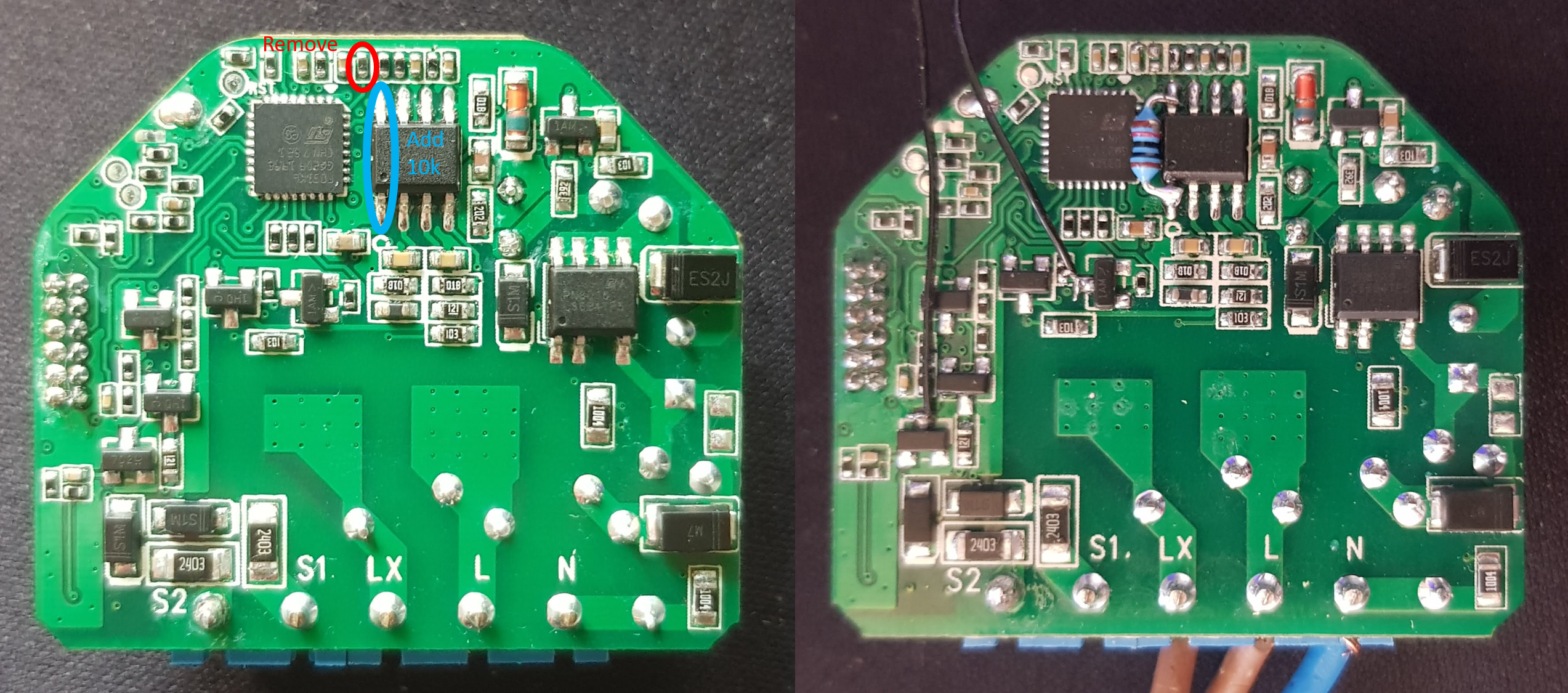
jamesturton
on 13 Sep 2020
Ohh and I forgot to mention, I have also ordered a couple of Shelly Dimmer 2 units so when they come I can make a start preparing firmware for those also!
jamesturton
on 13 Sep 2020
Excellent! Can't wait to upgrade all my Shelly Dimmer 2 devices to Tasmota!
stefxx
on 13 Sep 2020
For your information, I am developing a firmware for the Shelly Dimmer 2 using the Arduino IDE. See here: https://github.com/Mollayo/Shelly-Dimmer-2. This is a work in progress.
 Mollayo
on 13 Sep 2020
Mollayo
on 13 Sep 2020
[...] I have some updates on what I have been working on!
Super exciting update, thank you!
In addition to a binary build, can you also push the work in progress to a branch or your fork; it'd be great to see the code as the project progresses.
Also, can you clarify the state of your build. I have some Shelly Dimmer 2's sitting in the box until I can flash it with Tasmota. Is your build only for the original Shelly Dimmer?
Thanks again!
rca
on 13 Sep 2020
@Mollayo Nice work! Can you confirm if they are using the same communication protocol between the stm32 and the esp8266?
@rca I have may code for the stm32 here: https://github.com/jamesturton/shelly-dimmer-stm32
and my development branch of tasmota is here: https://github.com/jamesturton/Tasmota/tree/add_shelly_dimmer
Right now my tasmota branch is only compatible with Shelly dimmer 1, but as soon as my Shelly dimmer 2 units arrive I can begin porting the code over. I'm hoping that the communication protocol between the stm32 and the esp8266 will be the same as the old dimmer so it would just be a case of checking the pin-out on the esp-8266, to get a working version running. Later I can also work on developing the open source firmware to the stm32 on the Shelly dimmer 2 , but that might take a bit longer.
jamesturton
on 14 Sep 2020
@jamesturton The communication protocol is slightly different. See here: https://github.com/Mollayo/Shelly-Dimmer-2/blob/master/dimmer.cpp.
Mollayo
on 14 Sep 2020
@jamesturton thanks for the link to the branch! i'm trying to get it rebased onto the current development branch on my fork, and have a couple of questions.
Should feature6 be OR'd with the address 0x02000000: https://github.com/rca/Tasmota/blob/add_shelly_dimmer/tasmota/support_features.ino#L609
And do the new address offsets look correct in settings.h: https://github.com/rca/Tasmota/blob/add_shelly_dimmer/tasmota/settings.h#L615
Please confirm and I can fix up your original commits to keep the history clean; from there, feel free to bring the tweaked code into your fork. :)
rca
on 14 Sep 2020
@jamesturton glanced at your code. Ever considered using hardware sync instead of a timer?
edge90
on 14 Sep 2020
@rca Nice work, thanks for taking the time to do this! Your changes to support_features.ino and settings.h look good. The other thing that I guess would need changing is renaming xdrv_40_shelly_dimmer.ino to xdrv_44_shelly_dimmer.ino and all references of XDRV_40 in that file to XDRV_44.
@edge90 I'm using exti2_3_isr to synchronise (reset) the PWM timer TIM1. I'm also saving the value of TIM1 just before resetting it so that we can measure the line frequency to determine if it is 50 Hz or 60 Hz and set the PWM period accordingly. Any more comments on my code would be greatly appreciated!
jamesturton
on 15 Sep 2020
@jamesturton okay, updates made: https://github.com/rca/Tasmota/tree/add_shelly_dimmer
rca
on 15 Sep 2020
Some tools for analysing the communication protocol between the esp8266 and the STM32 on the Shelly Dimmer 2: https://github.com/Mollayo/Shelly-Dimmer-2-Reverse-Engineering
Mollayo
on 16 Sep 2020
I have spent a bit more time testing and cleaning up my code for the stm32 and now feel ready to release another version for other people to test. Thanks to the help of @rca I have also rebased this code to the current development branch in preparation for a PR! In this version, v0.8, it is upgrading the stm32 with the open source firmware I have developed here: shelly-dimmer-stm32 with firmware version v50.1. I have used such a high number as to never conflict with the stock Shelly firmware in case people wish to use that instead.
A note about this new version: I have not implemented the WarmupBrightness and WarmupTime in the stm32 firmware (yet...). I'm a little bit unsure if this feature should be included in the stm32 firmware or if it should be made a general feature to Tasmota (which would then fall outside the scope of this feature request). My feeling is that this feature could be useful to other dimmers which Tasmota could be flashed to, and therefore should be made as a separate feature in Tasmota.
If others would be kind enough to test this and report back any bugs they find that would be great!
tasmota_shelly_dimmer_v0.8.bin.gz
My Shelly dimmer 2 units arrived on Friday so this coming week I will work on porting this code (both Tasmota driver and stm32 firmware) over to that device. I have made a separate issue to track work on that here: #9412
jamesturton
on 27 Sep 2020
Hi James,
thank you for your incredible work! I have quickly tried the new 0.8 version. It seems to work great. I am experiencing some problems but it seems not directly connected with your changes:
- flickering - My both (different) LED lights are flickering. But it does not seem to be problem of your code. The official firmware has the same problem (https://www.facebook.com/groups/ShellyIoTCommunitySupport/permalink/3067655043333839). But now I can experiment with the code you wrote and try to fix it.
- I set both buttons to be in
SwitchMode 11- it absolutely does not behave as I would expect. It sends HOLD only five times and it also sends TOGGLE after the first HOLD while I'm holding button. I'll try to debug it later.
I have also built the firmware from your branch and it looks like the stm_v50.1.h should not be in /lib/stm32flash-1.0 but lib/stm32flash-1.0/fw/shelly/dimmer/ because the include in xdrv_44_shelly_dimmer.ino points there. stm_v50.1.h in your branch probably does not contain latest code. (it does not work at all for me) When I build it from https://github.com/jamesturton/shelly-dimmer-stm32 and place it to lib/stm32flash-1.0/fw/shelly/dimmer/ everything works.
petrjaros
on 28 Sep 2020
@petrjaros Yes, you are absolutely right! stm_v50.1.h was in the wrong directory. I have fixed this in my repo now, thanks for letting me know!
It's great that you are able to test out what might be causing the flickering with some bulbs - if you have any ideas of the cause, or a fix, that would be great to hear about.
I am also using SwitchMode 11 with the following rule from the Tasmota rules wiki page (even though it says SwitchMode 5 on the wiki I use SwitchMode 11 and SetOption32 10). Maybe this will help you getting it working?
```ON system#boot mem1 + ENDON
ON switch1#state=2 DO publish cmnd/kitchenLights/POWER TOGGLE ENDON
ON switch1#state=4 DO publish cmnd/kitchenLights/DIMMER %mem1% ENDON
ON switch1#state=5 DO mem1 - ENDON
ON switch1#state=6 DO mem1 + ENDON
jamesturton
on 28 Sep 2020
Hi guys,
I'm not using tasmota yet (I'm following this thread to try it out on a shelly dimmer 2 when possible), but you may want to check out this thread (especially the reactions of the shelly engineers) for the cause of flickering: https://www.shelly-support.eu/forum/index.php?thread/3730-dimmer-is-flashing/&postID=55253#post55253
I own a few shelly dimmer 2 modules and was troubled heavily by the flickering myself. Their latest release candidate update solved all flickering problems for me (they built in a sort of debouncer).
Best,
B.
 beligum
on 28 Sep 2020
beligum
on 28 Sep 2020
Finally figured out what was causing the problem with flickering. FW 0.8 fixed the flickering problem for me after I set ShdLeadingEdge 1. I knew that I should use trailing edge before but I missed that ShdLeadingEdge 0 means leading edge and ShdLeadingEdge 1 means trailing edge.
There is also a little glitch with setting ShdLeadingEdge to 1. The setting is forgotten after you upgrade stm32 firmware to another version.
I was not able to get this working with the original FW no matter which edge or debounce timeout i have used. The firmware from @jamesturton works without any magic debounce timeouts. Thanks for your hard work!
petrjaros
on 17 Oct 2020
There is also a little glitch with setting ShdLeadingEdge to 1. The setting is forgotten after you upgrade stm32 firmware to another version.
And now I have noticed the ShdLeadingEdge setting does not survive power outage too.
petrjaros
on 18 Oct 2020
@petrjaros Thanks for testing! Will fix the issue with the ShdLeadingEdge value not being saved asap! Do you think I should change the default to be trailing edge dimming if that works best with people experiencing 'flickering'?
jamesturton
on 18 Oct 2020
@jamesturton I think trailing edge as a default value would be better. See this message from a member of Shelly team https://www.shelly-support.eu/forum/index.php?thread/3730-dimmer-is-flashing/&postID=50985#post50985 :
"Use only traling edge calibration. Leading edge is only for old incandescent bulbs, and if you use for LED dimmable bulbs cause overtemperature and flickering time to time."
petrjaros
on 18 Oct 2020
I have made a new version of the Shelly dimmer driver: v1.0
- This version uses shelly-dimmer-stm32 version v51.0. In the future I intend to keep these versions numbers in-line, such that both version numbers will increase at every release even if there have been no changes to that specific section of the code.
- I have fixed up the issues that @petrjaros saw with the
ShdLeadingEdgecommand being inverted, and also this version saves the state ofShdLeadingEdgeeven after rebooting. This value now also defaults to trailing edge. - I have added pin names to all translation files (unfortunately I haven't actually translated the pin names) so now the pin names will show no matter which language is selected.
- This release also support using the Shelly dimmer 2! Please see #9412 regarding support for Shelly dimmer 2.
jamesturton
on 26 Oct 2020
Great to see you hit that firmware, and I'm really looking forward to flashing it.
I am wondering about a possibility of flashing it using the Ota endpoint on the official Shelly hardware, maybe by flashing something else first as space is quite limited. I've got around 127kb by the looks of it, any ideas? Or am I stuck flashing it by wires? And in thst case which wires?
 hklsiteimprove
on 29 Oct 2020
hklsiteimprove
on 29 Oct 2020
@hklsiteimprove can’t comment on the OTA flashing for the first instance, here is the Official Shelly Dimmer 2 Pinout I used early to flash the device.
 Scoobler
on 29 Oct 2020
Scoobler
on 29 Oct 2020
@hklsiteimprove can’t comment on the OTA flashing for the first instance, here is the Official Shelly Dimmer 2 Pinout I used early to flash the device.
Hey, where did you find/buy the cable to flash the Shelly ? I have an hard time finding pins that small.
jeremybdk
on 29 Oct 2020
@jeremybdk I was a bit rough handed, I have seen mention of a pin header small enough but was too impatient to wait for delivery, instead I used some DuPont wires (male to female) chopped off the male connector, then stripped back the wire and put a dab of solder (tinned the wire) on to keep the wire solid - that fitted perfectly in the header and allowed me to plug straight onto the USB programmer.
Scoobler
on 29 Oct 2020
I just succesfully flashed a Dimmer 2 by using this procedure: https://github.com/yaourdt/mgos-to-tasmota
After that, flash a tasmota_minimal.bin followed by tasmota_shelly_dimmer_v1.0.bin.gz.
stefxx
on 29 Oct 2020
Single core ethernet wire works great for this.
I was a bit rough handed, I have seen mention of a pin header small enough but was too impatient to wait for delivery, instead I used some DuPont wires (male to female) chopped off the male connector, then stripped back the wire and put a dab of solder (tinned the wire) on to keep the wire solid - that fitted perfectly in the header and allowed me to plug straight onto the USB programmer.
@Scoobler
Sorry for the wrong tag
sparkplug23
on 29 Oct 2020
Hey, where did you find/buy the cable to flash the Shelly ? I have an hard time finding pins that small.
24 gauge ethernet works great.
rca
on 29 Oct 2020
I just succesfully flashed a Dimmer 2 by using this procedure: https://github.com/yaourdt/mgos-to-tasmota
After that, flash a tasmota_minimal.bin followed by tasmota_shelly_dimmer_v1.0.bin.gz.
Will try that on my dimmer 1 tonight then :+1:
hklsiteimprove
on 30 Oct 2020
I just succesfully flashed a Dimmer 2 by using this procedure: https://github.com/yaourdt/mgos-to-tasmota
After that, flash a tasmota_minimal.bin followed by tasmota_shelly_dimmer_v1.0.bin.gz.
Will try that on my dimmer 1 tonight then :+1:
For those interested it worked like a charm 🍀
hklsiteimprove
on 31 Oct 2020
Thanks for all the work on this firmware!
Full power on/off works well but dimming seems to be quite hit and miss with fast flickering at brighter (80-90%) values, flashing at lower (50-60%) values and no light at all below approximately the 40% mark. Is there an idiots guide to calibration or any relevant settings to tweak dimming please?
I OTA flashed v1.0 via mgos-to-tasmota to a Shelly Dimmer 1 with 4 x 9W trailing edge compatible LED lights. I've left ShdLeadingEdge at the default, 0. Sydney, Australia so 230V @ 50Hz
rbswift
on 1 Nov 2020
Please be sure to review the code of conduct and be respectful of other users.
Keep in mind, this repository uses the Other.
![sentiment-bot[bot] picture](https://avatars3.githubusercontent.com/in/4544?v=4&s=40) sentiment-bot[bot]
on 1 Nov 2020
sentiment-bot[bot]
on 1 Nov 2020
Hi @rbswift , I have the Dimmer 2 and for the dimming range, turning LedTable Off made quite the difference.
stefxx
on 1 Nov 2020
Thanks @stefxx LedTable 0 does help quite a lot with the range but the lights are still flashing/flickering horribly compared with the stock shelly firmware. I've tried both ShdLeadingEdge 0 and 1 briefly and both flicker but I know these lights are intended for use with trailing edge.
rbswift
on 1 Nov 2020
I'd love to try and test to give more confidence, but as my Dimmer (1) is in the kitchen and not very easily reachable, I need to have some level of confidence before I can flash. I've got a couple of Shelly 1 & 2.5's running Tasmota already and know how to use mgos-to-tasmota.
Can I just flash this image, apply template (https://github.com/arendst/Tasmota/issues/9412#issuecomment-719919620), configure it the same way like the Shelly 1/2.5's, add it to HomeAssistant and it will just work (incl dimming)?
 daxy01
on 5 Nov 2020
daxy01
on 5 Nov 2020
@daxy01 If you only want to have to flash the dimmer once then maybe you should wait for an official release of the Shelly dimmer driver. The versions uploaded here are for testing and may include bugs. That said however, it is possible to update the units OTA so the process it update is relatively quick and doesn't require physical access to the device. Up to you!
@rbswift Thanks for your testing! If I make a special image for you with some extra logging, would it be possible for you to test some more? My guess is that it could be a problem with detecting the zero-crossing point of the mains voltage like described here: https://support.environexus.com/hc/en-us/articles/115001949128--LED-Lights-and-ripple-control-frequencies. Maybe it will be possible to add some software filtering of this ripple - will do some thinking and investigating.
jamesturton
on 6 Nov 2020
Hi @jamesturton Yes I'd be really very happy to do more testing.
I only know a bit about ripple control but will try to find out more. I thought it was only used at specific times of day for signalling to demand management devices whereas the flickering I am seeing is pretty consistent. If the ripple is continuous it could definitely be relevant.
FYI I have 1 dimmer with 4 lights, 2 dimmers with 2 lights each, and 1 dimmer with 2 slightly bigger lights. So far I've only updated the 4 light dimmer to tasmota but am happy to try others. Can the mgos-to-tasmota procedure be reversed to reinstate the originally shelly firmware otaURL if needed do you happen to know?
I have noticed there is also a definite buzzing from tasmota dimmer (or possibly the lights) when brightness is anything less that 100%. If the brightness is too low then the 4 lights seem to flash in a randomish cycle but I can probably avoid that by setting a minimum dimming level if I can get rid of the buzzing and flickering. Happy to video this if helpful.
I think I mentioned I'm on 50Hz here. Is it worth somehow checking the frequency has been correctly recognised?
I also noticed in the shelly firmware there is a fairly new "Anti-flickring debounce" setting that sounds potentially relevant but I've no idea what that does really. I never adjusted it from the default, 100.
Thanks again for all your work on the firmware!
rbswift
on 6 Nov 2020
Hi @rbswift, I'll add some notes from my testing.
I also hear buzzing from the dimmer when leading-edge dimming set (ShdLeadingEdge 1). When I change it to ShdLeadingEdge 0 (default value now) the buzzing sound stops. I also have 50hz here and use some dimmable Led bulbs from hobby market.
I can see barely noticeable flickering even when trailing-edge dimming is set when the brightness is below about 20%. I use minimum dimming level to avoid this problem.
"Anti-flickring debounce" feature in Shelly is there to avoid ripple control signal. I was experiencing very strong flickering (not comming from any ripple control) with the original firmware. The debounce setting helped a bit but still it was too strong. Tasmota firmware is the only one which makes the Shelly dimmer usable for me.
Hope it helps a bit.
petrjaros
on 6 Nov 2020
@rbswift Thanks for giving some more info!
I have no idea if it's possible to flash back to stock firmware, I assume it is, but I've never tried it. Please let me know if you do try!
I have heard of lot's of others mentioning this 'anti-flickring debounce' but I am still unaware of how this has been implemented by the Shelly devs. Any ideas how they might be implementing it would be very welcome!
The buzzing sounds like it could be caused from switching at 'non zero crossing points', so your guess about it not correctly identifying the frequency could be correct. I am attaching a new Tasmota image for you to test which prints out information about the average measured frequency and a 'standard deviation' like number (which I have called 'error points') which gives an indication how variable the frequency is. For reference this is how it looks on one of my dimmers:
14:58:55 SHD Frequency: 50,0 Hz (5019 error points)
14:58:56 SHD Frequency: 50,0 Hz (5018 error points)
14:58:57 SHD Frequency: 50,0 Hz (5020 error points)
14:58:58 SHD Frequency: 50,5 Hz (5018 error points)
14:58:59 SHD Frequency: 50,0 Hz (5019 error points)
14:59:00 SHD Frequency: 49,95 Hz (5039 error points)
14:59:01 SHD Frequency: 50,5 Hz (5057 error points)
14:59:02 SHD Frequency: 49,95 Hz (5048 error points)
14:59:03 SHD Frequency: 50,0 Hz (5046 error points)
14:59:04 SHD Frequency: 49,95 Hz (5033 error points)
14:59:05 SHD Frequency: 50,0 Hz (5036 error points)
14:59:06 SHD Frequency: 50,0 Hz (5038 error points)
14:59:07 SHD Frequency: 50,0 Hz (5039 error points)
14:59:08 SHD Frequency: 50,0 Hz (5044 error points)
14:59:09 SHD Frequency: 49,95 Hz (5031 error points)
14:59:10 SHD Frequency: 50,0 Hz (5046 error points)
14:59:11 SHD Frequency: 49,95 Hz (5034 error points)
14:59:12 SHD Frequency: 50,0 Hz (5044 error points)
14:59:13 SHD Frequency: 50,0 Hz (5045 error points)
14:59:14 SHD Frequency: 49,95 Hz (5037 error points)
14:59:15 SHD Frequency: 50,0 Hz (5047 error points)
14:59:16 SHD Frequency: 50,0 Hz (5059 error points)
14:59:17 SHD Frequency: 50,0 Hz (5048 error points)
14:59:18 SHD Frequency: 50,0 Hz (5048 error points)
14:59:19 SHD Frequency: 50,0 Hz (5055 error points)
14:59:20 SHD Frequency: 50,0 Hz (5050 error points)
14:59:21 SHD Frequency: 50,0 Hz (5055 error points)
14:59:22 SHD Frequency: 49,95 Hz (5038 error points)
14:59:23 SHD Frequency: 50,0 Hz (5042 error points)
14:59:24 SHD Frequency: 50,0 Hz (5036 error points)
14:59:25 SHD Frequency: 50,0 Hz (5039 error points)
14:59:26 SHD Frequency: 50,0 Hz (5042 error points)
14:59:27 SHD Frequency: 50,0 Hz (5048 error points)
14:59:28 SHD Frequency: 50,5 Hz (5041 error points)
14:59:29 SHD Frequency: 50,0 Hz (5040 error points)
14:59:30 SHD Frequency: 50,5 Hz (5051 error points)
14:59:31 SHD Frequency: 50,0 Hz (5044 error points)
14:59:32 SHD Frequency: 50,5 Hz (5061 error points)
14:59:33 SHD Frequency: 50,0 Hz (5043 error points)
14:59:34 SHD Frequency: 49,95 Hz (5036 error points)
14:59:35 SHD Frequency: 50,0 Hz (5040 error points)
14:59:36 SHD Frequency: 50,0 Hz (5048 error points)
14:59:37 SHD Frequency: 50,0 Hz (5052 error points)
I have just upgraded my Shelly Dimmer to Tasmota. I just took the plunge and it works just fine! Thanks @jamesturton
Two lessons learned:
1 - You can't use the tasmota_shelly_dimmer_v1.3.bin.gz URL as OTA.
_2 - The Shelly Dimmer is recognized as Switch and not as Light in Home Assistant, manual configuration is needed._
Update: #2 is not accurate, it does work as expected.
One observation:
- When dimming the LED's (3x 4W) to <50%, the LEDs so seem to flicker a bit, as if they have a low refresh-rate. This was not present with the original firmware.
Here are the full steps should anyone like to repeat this:
1) OTA Upgrade mgos-to-tasmota: https://github.com/yaourdt/mgos-to-tasmota
1a) Connect to local tasmota-XYZ WiFi, login, add local WiFi details
2) Install tasmota-minimal via OTA using: http://ota.tasmota.com/tasmota/tasmota-minimal.bin
3) Download Dimmer v1.3 locally: https://github.com/arendst/Tasmota/files/5489877/tasmota_shelly_dimmer_v1.3.bin.gz
4) Upgrade using local downloaded file
5) Apply template:
Shelly Dimmer 1
{"NAME":"Shelly Dimmer 1","GPIO":[0,3200,0,3232,5504,5536,0,0,192,0,193,288,0,4736],"FLAG":0,"BASE":18}
Shelly Dimmer 2
{"NAME":"Shelly Dimmer 2","GPIO":[0,3200,0,3232,5504,5536,0,0,193,0,192,0,320,4736],"FLAG":0,"BASE":18}
6) Configure MQTT (remember what you add as Topic, you'll need this for step 8)
7) Using Console setup few settings:
Turn off Gamma Control: LedTable Off
Enable fading: Fade On
Set Dimmer Range: DimmerRange 25,100
Announce to Home-Assistant: SetOption19 1
8) Configure MQTT Light in Home Assistant. Can be done in GUI at the Integrations settings, work fine when SO19 has been set.
daxy01
on 6 Nov 2020
ignore this - i fixed my upload problem :)
will test the frequency version and post results soon - thanks
rbswift
on 7 Nov 2020
@jamesturton here's some logging. Hope it's revealing!? Looks like my frequency is consistently a bit higher than yours?
00:00:03 SHD Frequency: 50,40 Hz (9983 error points)
00:00:03 SHD Frequency: 50,45 Hz (5652 error points)
00:00:04 SHD Frequency: 50,45 Hz (5698 error points)
00:00:05 SHD Frequency: 50,45 Hz (5706 error points)
00:00:05 WIF: Connected
00:37:21 HTP: Web server active on dining with IP address 192.168.188.33
00:37:21 SHD Frequency: 50,45 Hz (5702 error points)
00:37:22 MQT: Attempting connection...
00:37:22 MQT: Connected
00:37:22 MQT: tele/dining/LWT = Online (retained)
00:37:22 MQT: cmnd/dining/POWER =
00:37:22 MQT: tele/dining/INFO1 = {"Module":"Shelly Dimmer 1","Version":"9.0.0.3(shelly-dimmer)","FallbackTopic":"cmnd/dining_fb/","GroupTopic":"cmnd/tasmotas/"}
00:37:22 MQT: tele/dining/INFO2 = {"WebServerMode":"Admin","Hostname":"dining","IPAddress":"192.168.188.33"}
00:37:22 MQT: tele/dining/INFO3 = {"RestartReason":"Software/System restart"}
00:37:22 MQT: stat/dining/RESULT = {"POWER":"ON"}
00:37:22 MQT: stat/dining/POWER = ON
00:37:22 SHD Frequency: 50,45 Hz (5706 error points)
00:37:23 QPC: Reset
00:37:23 SHD Frequency: 50,45 Hz (5694 error points)
00:37:24 SHD Frequency: 50,40 Hz (5690 error points)
00:37:25 SHD Frequency: 50,45 Hz (5695 error points)
00:37:26 MQT: tele/dining/STATE = {"Time":"2020-11-07T00:37:26","Uptime":"0T00:00:11","UptimeSec":11,"Heap":26,"SleepMode":"Dynamic","Sleep":10,"LoadAvg":84,"MqttCount":1,"POWER":"ON","Dimmer":100,"Fade":"OFF","Speed":1,"LedTable":"OFF","Wifi":{"AP":1,"SSId":"Teh Interwebz","BSSId":"08:96:D7:8A:94:84","Channel":6,"RSSI":82,"Signal":-59,"LinkCount":1,"Downtime":"0T00:00:05"}}
00:37:26 MQT: tele/dining/SENSOR = {"Time":"2020-11-07T00:37:26","Switch1":"OFF","Switch2":"OFF","ANALOG":{"Temperature":52.7},"ENERGY":{"TotalStartTime":"2020-11-05T11:23:12","Total":0.000,"Yesterday":0.000,"Today":0.000,"Period":0,"Power":28},"TempUnit":"C"}
00:37:26 SHD Frequency: 50,45 Hz (5682 error points)
00:37:26 MQT: stat/dining/RESULT = {"POWER":"ON","Dimmer":79}
00:37:27 SHD Frequency: 50,45 Hz (5481 error points)
00:37:28 MQT: stat/dining/RESULT = {"POWER":"ON","Dimmer":48}
00:37:28 SHD Frequency: 50,45 Hz (5296 error points)
00:37:29 SHD Frequency: 50,40 Hz (5269 error points)
00:37:29 MQT: stat/dining/RESULT = {"POWER":"ON","Dimmer":30}
00:37:30 SHD Frequency: 50,40 Hz (5319 error points)
00:37:30 MQT: stat/dining/RESULT = {"POWER":"ON","Dimmer":15}
00:37:31 SHD Frequency: 50,40 Hz (5327 error points)
00:37:32 MQT: stat/dining/RESULT = {"POWER":"ON","Dimmer":4}
00:37:32 SHD Frequency: 50,40 Hz (5344 error points)
00:37:33 SHD Frequency: 50,40 Hz (5367 error points)
00:37:34 MQT: stat/dining/RESULT = {"POWER":"ON","Dimmer":8}
00:37:34 SHD Frequency: 50,40 Hz (5360 error points)
00:37:35 MQT: stat/dining/RESULT = {"POWER":"ON","Dimmer":12}
00:37:35 SHD Frequency: 50,35 Hz (5382 error points)
00:37:36 SHD Frequency: 50,40 Hz (5403 error points)
00:37:37 SHD Frequency: 50,40 Hz (5372 error points)
00:37:38 SHD Frequency: 50,40 Hz (5380 error points)
00:37:38 MQT: stat/dining/RESULT = {"POWER":"ON","Dimmer":23}
00:37:39 SHD Frequency: 50,40 Hz (5371 error points)
00:37:40 MQT: stat/dining/RESULT = {"POWER":"ON","Dimmer":21}
00:37:40 SHD Frequency: 50,45 Hz (5392 error points)
00:37:41 MQT: stat/dining/RESULT = {"POWER":"ON","Dimmer":18}
00:37:41 SHD Frequency: 50,40 Hz (5388 error points)
00:37:42 MQT: stat/dining/RESULT = {"POWER":"ON","Dimmer":59}
00:37:42 SHD Frequency: 50,40 Hz (5390 error points)
00:37:43 MQT: stat/dining/RESULT = {"POWER":"ON","Dimmer":45}
00:37:43 SHD Frequency: 50,40 Hz (5303 error points)
00:37:44 SHD Frequency: 50,45 Hz (5318 error points)
00:37:45 SHD Frequency: 50,40 Hz (5344 error points)
00:37:46 SHD Frequency: 50,40 Hz (5372 error points)
00:37:47 SHD Frequency: 50,40 Hz (5368 error points)
00:37:48 EXS: Set Power, Power 0x00
00:37:48 MQT: stat/dining/RESULT = {"POWER":"OFF"}
00:37:48 MQT: stat/dining/POWER = OFF
00:37:48 SHD Frequency: 50,35 Hz (5391 error points)
00:37:49 SHD Frequency: 50,40 Hz (5421 error points)
00:37:50 SHD Frequency: 50,40 Hz (5397 error points)
00:37:51 SHD Frequency: 50,35 Hz (5399 error points)
00:37:52 SHD Frequency: 50,40 Hz (5405 error points)
00:37:53 SHD Frequency: 50,40 Hz (5415 error points)
00:37:55 SHD Frequency: 50,35 Hz (5391 error points)
00:37:56 SHD Frequency: 50,40 Hz (5400 error points)
00:37:57 SHD Frequency: 50,40 Hz (5409 error points)
00:37:58 SHD Frequency: 50,40 Hz (5398 error points)
00:37:59 SHD Frequency: 50,40 Hz (5401 error points)
00:38:00 SHD Frequency: 50,35 Hz (5388 error points)
00:38:01 SHD Frequency: 50,40 Hz (5415 error points)
00:38:02 SHD Frequency: 50,40 Hz (5391 error points)
00:38:03 SHD Frequency: 50,40 Hz (5430 error points)
00:38:04 SHD Frequency: 50,35 Hz (5425 error points)
00:38:05 SHD Frequency: 50,40 Hz (5418 error points)
00:38:06 SHD Frequency: 50,40 Hz (5444 error points)
00:38:07 SHD Frequency: 50,40 Hz (5425 error points)
00:38:08 SHD Frequency: 50,35 Hz (5398 error points)
00:38:09 SHD Frequency: 50,40 Hz (5368 error points)
00:38:10 SHD Frequency: 50,35 Hz (5377 error points)
00:38:11 SHD Frequency: 50,40 Hz (5380 error points)
00:38:12 SHD Frequency: 50,35 Hz (5390 error points)
00:38:13 SHD Frequency: 50,40 Hz (5403 error points)
00:38:14 SHD Frequency: 50,40 Hz (5396 error points)
00:38:15 SHD Frequency: 50,40 Hz (5392 error points)
00:38:16 SHD Frequency: 50,35 Hz (5423 error points)
00:38:17 SHD Frequency: 50,40 Hz (5406 error points)
00:38:18 SHD Frequency: 50,40 Hz (5405 error points)
00:38:19 SHD Frequency: 50,40 Hz (5401 error points)
00:38:20 SHD Frequency: 50,35 Hz (5388 error points)
00:38:21 SHD Frequency: 50,40 Hz (5387 error points)
00:38:22 SHD Frequency: 50,35 Hz (5406 error points)
00:38:23 SHD Frequency: 50,40 Hz (5417 error points)
00:38:24 SHD Frequency: 50,40 Hz (5400 error points)
00:38:25 SHD Frequency: 50,45 Hz (5406 error points)
00:38:26 SHD Frequency: 50,45 Hz (5414 error points)
00:38:27 SHD Frequency: 50,40 Hz (5425 error points)
00:38:28 SHD Frequency: 50,45 Hz (5426 error points)
00:38:29 SHD Frequency: 50,40 Hz (5421 error points)
00:38:30 SHD Frequency: 50,45 Hz (5421 error points)
00:38:31 SHD Frequency: 50,45 Hz (5418 error points)
00:38:32 SHD Frequency: 50,45 Hz (5411 error points)
00:38:33 SHD Frequency: 50,40 Hz (5409 error points)
00:38:34 SHD Frequency: 50,40 Hz (5398 error points)
00:38:35 SHD Frequency: 50,40 Hz (5403 error points)
00:38:36 SHD Frequency: 50,40 Hz (5418 error points)
00:38:37 SHD Frequency: 50,40 Hz (5419 error points)
00:38:38 SHD Frequency: 50,45 Hz (5424 error points)
00:38:39 SHD Frequency: 50,40 Hz (5404 error points)
00:38:40 SHD Frequency: 50,40 Hz (5400 error points)
00:38:41 SHD Frequency: 50,35 Hz (5403 error points)
00:38:42 SHD Frequency: 50,40 Hz (5446 error points)
00:38:43 SHD Frequency: 50,40 Hz (5459 error points)
00:38:44 SHD Frequency: 50,35 Hz (5444 error points)
00:38:45 SHD Frequency: 50,40 Hz (5474 error points)
00:38:46 SHD Frequency: 50,40 Hz (5453 error points)
00:38:47 SHD Frequency: 50,40 Hz (5468 error points)
00:38:48 SHD Frequency: 50,40 Hz (5466 error points)
00:38:49 SHD Frequency: 50,40 Hz (5446 error points)
00:38:50 SHD Frequency: 50,35 Hz (5419 error points)
00:38:51 SHD Frequency: 50,40 Hz (5452 error points)
00:38:52 SHD Frequency: 50,40 Hz (5429 error points)
00:38:53 SHD Frequency: 50,40 Hz (5440 error points)
00:38:54 SHD Frequency: 50,35 Hz (5435 error points)
00:38:55 SHD Frequency: 50,40 Hz (5439 error points)
00:38:56 SHD Frequency: 50,40 Hz (5458 error points)
00:38:57 SHD Frequency: 50,35 Hz (5452 error points)
00:38:58 SHD Frequency: 50,40 Hz (5455 error points)
00:38:59 SHD Frequency: 50,40 Hz (5461 error points)
00:39:00 SHD Frequency: 50,40 Hz (5461 error points)
00:39:01 SHD Frequency: 50,35 Hz (5480 error points)
00:39:02 SHD Frequency: 50,40 Hz (5484 error points)
00:39:03 SHD Frequency: 50,35 Hz (5513 error points)
00:39:04 SHD Frequency: 50,40 Hz (5519 error points)
00:39:05 SHD Frequency: 50,35 Hz (5521 error points)
00:39:06 SHD Frequency: 50,35 Hz (5489 error points)
00:39:07 SHD Frequency: 50,35 Hz (5477 error points)
00:39:08 SHD Frequency: 50,40 Hz (5461 error points)
@jamesturton I've loaded the debugging image as well as I might have the same issue as @rbswift (flickering when dimming, feels like low refresh rate/stroboscope idea). Here are my logs, hope this helps!
00:00:00 CFG: Loaded from flash at FB, Count 236
00:00:00 QPC: Reset
00:00:00 EXS: Set Power, Power 0x00
00:00:00 Project tasmota Shelly Dimmer Keuken Version 9.0.0.3(shelly-dimmer)-2_7_4_5
00:00:00 SHD Shelly Dimmer Driver v1.4
00:00:00 SHD Starting Tx 1 Rx 3
00:00:00 SNS: Hardware Serial
00:00:00 SHD Sending version command
00:00:00 SHD Shelly Dimmer Co-processor Version v51.3
00:00:00 SHD Updating firmware from v51.3 to v51.4 with 14124 bytes
00:00:02 SHD Sending version command
00:00:02 SHD Loading params: 341,2,0,0,0
00:00:02 SHD Frequency: 8,84 Hz (7210 error points)
00:00:03 SHD Frequency: 50,15 Hz (6488 error points)
00:00:04 SHD Frequency: 50,10 Hz (6450 error points)
00:00:05 SHD Frequency: 50,10 Hz (6434 error points)
00:00:05 RSL: stat/tasmota-keuken/SWITCH1T = {"TRIG":"TOGGLE"}
00:00:05 EXS: Set Power, Power 0x01
00:00:05 RSL: tele/tasmota-keuken/STATE = {"Time":"1970-01-01T00:00:05","Uptime":"0T00:00:04","UptimeSec":4,"Heap":28,"SleepMode":"Dynamic","Sleep":10,"LoadAvg":4,"MqttCount":0,"POWER":"ON","Dimmer":12,"Fade":"ON","Speed":1,"LedTable":"OFF"}
00:00:05 RSL: stat/tasmota-keuken/RESULT = {"POWER":"ON"}
00:00:05 RSL: stat/tasmota-keuken/POWER = ON
00:00:06 SHD Frequency: 50,10 Hz (6467 error points)
00:00:06 WIF: Connecting to AP1 Daxy Channel 6 BSSId B6:FB:E4:1B:50:0C in mode 11N as tasmota-keuken-7987...
00:00:07 SHD Frequency: 50,10 Hz (6468 error points)
00:00:07 SHD Frequency: 50,10 Hz (6435 error points)
00:00:07 WIF: Connected
11:39:48 HTP: Web server active on tasmota-keuken-7987 with IP address 192.168.1.113
11:39:48 SHD Frequency: 50,10 Hz (6433 error points)
11:39:49 MQT: Attempting connection...
11:39:49 MQT: Connected
11:39:49 MQT: tele/tasmota-keuken/LWT = Online (retained)
11:39:49 MQT: cmnd/tasmota-keuken/POWER =
11:39:49 MQT: tele/tasmota-keuken/INFO1 = {"Module":"Shelly Dimmer 1","Version":"9.0.0.3(shelly-dimmer)","FallbackTopic":"cmnd/shelly-dimmer-keuken_fb/","GroupTopic":"cmnd/tasmotas/"}
11:39:49 MQT: tele/tasmota-keuken/INFO2 = {"WebServerMode":"Admin","Hostname":"tasmota-keuken-7987","IPAddress":"192.168.1.113"}
11:39:49 MQT: tele/tasmota-keuken/INFO3 = {"RestartReason":"Software/System restart"}
11:39:49 MQT: stat/tasmota-keuken/RESULT = {"POWER":"ON"}
11:39:49 MQT: stat/tasmota-keuken/POWER = ON
11:39:49 SHD Frequency: 50,10 Hz (6430 error points)
11:39:50 MQT: homeassistant/sensor/D0DF33_ANALOG_Temperature/config = {"name":"Shelly Dimmer Keuken ANALOG Temperature","stat_t":"tele/tasmota-keuken/SENSOR","avty_t":"tele/tasmota-keuken/LWT","pl_avail":"Online","pl_not_avail":"Offline","uniq_id":"D0DF33_ANALOG_Temperature","dev":{"ids":["D0DF33"]},"unit_of_meas":"°C","dev_cla":"temperature","frc_upd":true,"val_tpl":"{{value_json['ANALOG']['Temperature']}}"} (retained)
11:39:50 MQT: homeassistant/sensor/D0DF33_ENERGY_TotalStartTime/config = {"name":"Shelly Dimmer Keuken ENERGY TotalStartTime","stat_t":"tele/tasmota-keuken/SENSOR","avty_t":"tele/tasmota-keuken/LWT","pl_avail":"Online","pl_not_avail":"Offline","uniq_id":"D0DF33_ENERGY_TotalStartTime","dev":{"ids":["D0DF33"]},"unit_of_meas":" ","ic":"mdi:progress-clock","frc_upd":true,"val_tpl":"{{value_json['ENERGY']['TotalStartTime']}}"} (retained)
11:39:50 MQT: homeassistant/sensor/D0DF33_ENERGY_Total/config = {"name":"Shelly Dimmer Keuken ENERGY Total","stat_t":"tele/tasmota-keuken/SENSOR","avty_t":"tele/tasmota-keuken/LWT","pl_avail":"Online","pl_not_avail":"Offline","uniq_id":"D0DF33_ENERGY_Total","dev":{"ids":["D0DF33"]},"unit_of_meas":"kWh","dev_cla":"power","frc_upd":true,"val_tpl":"{{value_json['ENERGY']['Total']}}"} (retained)
11:39:50 MQT: homeassistant/sensor/D0DF33_ENERGY_Yesterday/config = {"name":"Shelly Dimmer Keuken ENERGY Yesterday","stat_t":"tele/tasmota-keuken/SENSOR","avty_t":"tele/tasmota-keuken/LWT","pl_avail":"Online","pl_not_avail":"Offline","uniq_id":"D0DF33_ENERGY_Yesterday","dev":{"ids":["D0DF33"]},"unit_of_meas":"kWh","dev_cla":"power","frc_upd":true,"val_tpl":"{{value_json['ENERGY']['Yesterday']}}"} (retained)
11:39:50 MQT: homeassistant/sensor/D0DF33_ENERGY_Today/config = {"name":"Shelly Dimmer Keuken ENERGY Today","stat_t":"tele/tasmota-keuken/SENSOR","avty_t":"tele/tasmota-keuken/LWT","pl_avail":"Online","pl_not_avail":"Offline","uniq_id":"D0DF33_ENERGY_Today","dev":{"ids":["D0DF33"]},"unit_of_meas":"kWh","dev_cla":"power","frc_upd":true,"val_tpl":"{{value_json['ENERGY']['Today']}}"} (retained)
11:39:50 MQT: homeassistant/sensor/D0DF33_ENERGY_Power/config = {"name":"Shelly Dimmer Keuken ENERGY Power","stat_t":"tele/tasmota-keuken/SENSOR","avty_t":"tele/tasmota-keuken/LWT","pl_avail":"Online","pl_not_avail":"Offline","uniq_id":"D0DF33_ENERGY_Power","dev":{"ids":["D0DF33"]},"unit_of_meas":"W","dev_cla":"power","frc_upd":true,"val_tpl":"{{value_json['ENERGY']['Power']}}"} (retained)
11:39:50 MQT: homeassistant/light/D0DF33_LI_1/config = {"name":"Keuken schakelaar","stat_t":"tele/tasmota-keuken/STATE","avty_t":"tele/tasmota-keuken/LWT","pl_avail":"Online","pl_not_avail":"Offline","cmd_t":"cmnd/tasmota-keuken/POWER","val_tpl":"{{value_json.POWER}}","pl_off":"OFF","pl_on":"ON","uniq_id":"D0DF33_LI_1","dev":{"ids":["D0DF33"]},"bri_cmd_t":"cmnd/tasmota-keuken/Dimmer","bri_stat_t":"tele/tasmota-keuken/STATE","bri_scl":100,"on_cmd_type":"brightness","bri_val_tpl":"{{value_json.Dimmer}}"} (retained)
11:39:50 MQT: homeassistant/sensor/D0DF33_status/config = {"name":"Shelly Dimmer Keuken status","stat_t":"tele/tasmota-keuken/HASS_STATE","avty_t":"tele/tasmota-keuken/LWT","pl_avail":"Online","pl_not_avail":"Offline","json_attr_t":"tele/tasmota-keuken/HASS_STATE","unit_of_meas":"%","val_tpl":"{{value_json['RSSI']}}","ic":"mdi:information-outline","uniq_id":"D0DF33_status","dev":{"ids":["D0DF33"],"name":"Shelly Dimmer Keuken","mdl":"Shelly Dimmer 1","sw":"9.0.0.3(shelly-dimmer)","mf":"Tasmota"}} (retained)
11:39:50 SHD Frequency: 50,10 Hz (6441 error points)
11:39:51 SHD Frequency: 50,10 Hz (6442 error points)
11:39:52 SHD Frequency: 50,10 Hz (6448 error points)
11:39:53 MQT: tele/tasmota-keuken/STATE = {"Time":"2020-11-08T11:39:53","Uptime":"0T00:00:13","UptimeSec":13,"Heap":25,"SleepMode":"Dynamic","Sleep":10,"LoadAvg":97,"MqttCount":1,"POWER":"ON","Dimmer":12,"Fade":"ON","Speed":1,"LedTable":"OFF","Wifi":{"AP":1,"SSId":"Daxy","BSSId":"B6:FB:E4:1B:50:0C","Channel":6,"RSSI":54,"Signal":-73,"LinkCount":1,"Downtime":"0T00:00:07"}}
11:39:53 MQT: tele/tasmota-keuken/SENSOR = {"Time":"2020-11-08T11:39:53","Switch1":"ON","Switch2":"OFF","ANALOG":{"Temperature":45.4},"ENERGY":{"TotalStartTime":"2020-11-06T15:36:51","Total":5955.004,"Yesterday":0.000,"Today":2976.304,"Period":0,"Power":3},"TempUnit":"C"}
11:39:53 SHD Frequency: 50,10 Hz (6475 error points)
11:39:54 SHD Frequency: 50,10 Hz (6484 error points)
11:39:55 SHD Frequency: 50,10 Hz (6475 error points)
11:39:56 SHD Frequency: 50,10 Hz (6459 error points)
11:39:57 SHD Frequency: 50,5 Hz (6468 error points)
11:39:58 SHD Frequency: 50,15 Hz (6449 error points)
11:39:59 SHD Frequency: 50,10 Hz (6455 error points)
11:40:00 SHD Frequency: 50,10 Hz (6444 error points)
11:40:01 SHD Frequency: 50,5 Hz (6415 error points)
11:40:02 SHD Frequency: 50,15 Hz (6448 error points)
11:40:03 SHD Frequency: 50,10 Hz (6434 error points)
11:40:04 SHD Frequency: 50,10 Hz (6424 error points)
11:40:05 SHD Frequency: 50,10 Hz (6432 error points)
11:40:06 SHD Frequency: 50,10 Hz (6435 error points)
11:40:07 SHD Frequency: 50,10 Hz (6412 error points)
11:40:08 SHD Frequency: 50,10 Hz (6417 error points)
11:40:09 SHD Frequency: 50,10 Hz (6427 error points)
11:40:10 SHD Frequency: 50,10 Hz (6444 error points)
11:40:11 SHD Frequency: 50,5 Hz (6426 error points)
11:40:12 SHD Frequency: 50,15 Hz (6446 error points)
11:40:13 SHD Frequency: 50,10 Hz (6432 error points)
11:40:14 MQT: tele/tasmota-keuken/STATE = {"Time":"2020-11-08T11:40:14","Uptime":"0T00:00:34","UptimeSec":34,"Heap":24,"SleepMode":"Dynamic","Sleep":10,"LoadAvg":99,"MqttCount":1,"POWER":"ON","Dimmer":53,"Fade":"ON","Speed":1,"LedTable":"OFF","Wifi":{"AP":1,"SSId":"Daxy","BSSId":"B6:FB:E4:1B:50:0C","Channel":6,"RSSI":48,"Signal":-76,"LinkCount":1,"Downtime":"0T00:00:07"}}
11:40:14 MQT: stat/tasmota-keuken/RESULT = {"POWER":"ON","Dimmer":53}
11:40:14 SHD Frequency: 50,10 Hz (6429 error points)
11:40:15 SHD Frequency: 50,10 Hz (6406 error points)
11:40:16 SHD Frequency: 50,10 Hz (6420 error points)
11:40:17 MQT: tele/tasmota-keuken/STATE = {"Time":"2020-11-08T11:40:17","Uptime":"0T00:00:37","UptimeSec":37,"Heap":24,"SleepMode":"Dynamic","Sleep":10,"LoadAvg":99,"MqttCount":1,"POWER":"ON","Dimmer":97,"Fade":"ON","Speed":1,"LedTable":"OFF","Wifi":{"AP":1,"SSId":"Daxy","BSSId":"B6:FB:E4:1B:50:0C","Channel":6,"RSSI":48,"Signal":-76,"LinkCount":1,"Downtime":"0T00:00:07"}}
11:40:17 MQT: stat/tasmota-keuken/RESULT = {"POWER":"ON","Dimmer":97}
11:40:17 SHD Frequency: 50,10 Hz (6447 error points)
11:40:18 MQT: tele/tasmota-keuken/STATE = {"Time":"2020-11-08T11:40:18","Uptime":"0T00:00:38","UptimeSec":38,"Heap":24,"SleepMode":"Dynamic","Sleep":10,"LoadAvg":99,"MqttCount":1,"POWER":"ON","Dimmer":48,"Fade":"ON","Speed":1,"LedTable":"OFF","Wifi":{"AP":1,"SSId":"Daxy","BSSId":"B6:FB:E4:1B:50:0C","Channel":6,"RSSI":50,"Signal":-75,"LinkCount":1,"Downtime":"0T00:00:07"}}
11:40:18 MQT: stat/tasmota-keuken/RESULT = {"POWER":"ON","Dimmer":48}
11:40:18 SHD Frequency: 50,10 Hz (6484 error points)
11:40:19 SHD Frequency: 50,10 Hz (6441 error points)
11:40:20 SHD Frequency: 50,10 Hz (6433 error points)
11:40:21 MQT: tele/tasmota-keuken/STATE = {"Time":"2020-11-08T11:40:21","Uptime":"0T00:00:41","UptimeSec":41,"Heap":24,"SleepMode":"Dynamic","Sleep":10,"LoadAvg":99,"MqttCount":1,"POWER":"ON","Dimmer":19,"Fade":"ON","Speed":1,"LedTable":"OFF","Wifi":{"AP":1,"SSId":"Daxy","BSSId":"B6:FB:E4:1B:50:0C","Channel":6,"RSSI":50,"Signal":-75,"LinkCount":1,"Downtime":"0T00:00:07"}}
11:40:21 MQT: stat/tasmota-keuken/RESULT = {"POWER":"ON","Dimmer":19}
11:40:21 SHD Frequency: 50,10 Hz (6435 error points)
11:40:22 SHD Frequency: 50,10 Hz (6426 error points)
11:40:23 SHD Frequency: 50,10 Hz (6412 error points)
11:40:24 EXS: Set Power, Power 0x00
11:40:24 MQT: tele/tasmota-keuken/STATE = {"Time":"2020-11-08T11:40:24","Uptime":"0T00:00:44","UptimeSec":44,"Heap":24,"SleepMode":"Dynamic","Sleep":50,"LoadAvg":99,"MqttCount":1,"POWER":"OFF","Dimmer":19,"Fade":"ON","Speed":1,"LedTable":"OFF","Wifi":{"AP":1,"SSId":"Daxy","BSSId":"B6:FB:E4:1B:50:0C","Channel":6,"RSSI":50,"Signal":-75,"LinkCount":1,"Downtime":"0T00:00:07"}}
11:40:24 MQT: stat/tasmota-keuken/RESULT = {"POWER":"OFF"}
11:40:24 MQT: stat/tasmota-keuken/POWER = OFF
11:40:24 SHD Frequency: 50,5 Hz (6404 error points)
11:40:25 SHD Frequency: 50,10 Hz (6406 error points)
11:40:26 SHD Frequency: 50,10 Hz (6410 error points)
11:40:26 EXS: Set Power, Power 0x01
11:40:26 MQT: tele/tasmota-keuken/STATE = {"Time":"2020-11-08T11:40:26","Uptime":"0T00:00:46","UptimeSec":46,"Heap":24,"SleepMode":"Dynamic","Sleep":10,"LoadAvg":22,"MqttCount":1,"POWER":"ON","Dimmer":19,"Fade":"ON","Speed":1,"LedTable":"OFF","Wifi":{"AP":1,"SSId":"Daxy","BSSId":"B6:FB:E4:1B:50:0C","Channel":6,"RSSI":50,"Signal":-75,"LinkCount":1,"Downtime":"0T00:00:07"}}
11:40:26 MQT: stat/tasmota-keuken/RESULT = {"POWER":"ON"}
11:40:26 MQT: stat/tasmota-keuken/POWER = ON
11:40:27 SHD Frequency: 50,5 Hz (6414 error points)
11:40:28 SHD Frequency: 50,15 Hz (6442 error points)
11:40:29 SHD Frequency: 50,10 Hz (6456 error points)
11:40:30 MQT: tele/tasmota-keuken/STATE = {"Time":"2020-11-08T11:40:30","Uptime":"0T00:00:50","UptimeSec":50,"Heap":24,"SleepMode":"Dynamic","Sleep":10,"LoadAvg":39,"MqttCount":1,"POWER":"ON","Dimmer":50,"Fade":"ON","Speed":1,"LedTable":"OFF","Wifi":{"AP":1,"SSId":"Daxy","BSSId":"B6:FB:E4:1B:50:0C","Channel":6,"RSSI":48,"Signal":-76,"LinkCount":1,"Downtime":"0T00:00:07"}}
11:40:30 MQT: stat/tasmota-keuken/RESULT = {"POWER":"ON","Dimmer":50}
11:40:30 SHD Frequency: 50,5 Hz (6440 error points)
11:40:31 SHD Frequency: 50,15 Hz (6455 error points)
11:40:32 SHD Frequency: 50,10 Hz (6461 error points)
11:40:33 SHD Frequency: 50,5 Hz (6448 error points)
11:40:34 SHD Frequency: 50,10 Hz (6454 error points)
11:40:35 SHD Frequency: 50,15 Hz (6458 error points)
11:40:35 MQT: tele/tasmota-keuken/STATE = {"Time":"2020-11-08T11:40:35","Uptime":"0T00:00:55","UptimeSec":55,"Heap":24,"SleepMode":"Dynamic","Sleep":10,"LoadAvg":61,"MqttCount":1,"POWER":"ON","Dimmer":38,"Fade":"ON","Speed":1,"LedTable":"OFF","Wifi":{"AP":1,"SSId":"Daxy","BSSId":"B6:FB:E4:1B:50:0C","Channel":6,"RSSI":46,"Signal":-77,"LinkCount":1,"Downtime":"0T00:00:07"}}
11:40:35 MQT: stat/tasmota-keuken/RESULT = {"POWER":"ON","Dimmer":38}
11:40:36 SHD Frequency: 50,5 Hz (6446 error points)
11:40:37 SHD Frequency: 50,10 Hz (6434 error points)
11:40:38 SHD Frequency: 50,5 Hz (6431 error points)
11:40:39 SHD Frequency: 50,10 Hz (6430 error points)
11:40:40 SHD Frequency: 50,10 Hz (6424 error points)
11:40:41 SHD Frequency: 50,10 Hz (6436 error points)
11:40:42 SHD Frequency: 50,10 Hz (6447 error points)
11:40:43 EXS: Set Power, Power 0x00
11:40:43 MQT: tele/tasmota-keuken/STATE = {"Time":"2020-11-08T11:40:43","Uptime":"0T00:01:03","UptimeSec":63,"Heap":24,"SleepMode":"Dynamic","Sleep":50,"LoadAvg":83,"MqttCount":1,"POWER":"OFF","Dimmer":38,"Fade":"ON","Speed":1,"LedTable":"OFF","Wifi":{"AP":1,"SSId":"Daxy","BSSId":"B6:FB:E4:1B:50:0C","Channel":6,"RSSI":48,"Signal":-76,"LinkCount":1,"Downtime":"0T00:00:07"}}
11:40:43 MQT: stat/tasmota-keuken/RESULT = {"POWER":"OFF"}
11:40:43 MQT: stat/tasmota-keuken/POWER = OFF
11:40:43 SHD Frequency: 50,15 Hz (6424 error points)
11:40:44 SHD Frequency: 50,5 Hz (6412 error points)
11:40:45 SHD Frequency: 50,15 Hz (6423 error points)
@jamesturton I also noticed a possible problem with poweronstate.
When my dimmer1 power status is off and I restart with poweronstate=3 then the lights come on but Tasmota still reports the status as off.
rbswift
on 8 Nov 2020
@jamesturton I also noticed a possible problem with poweronstate.
When my dimmer1 power status is off and I restart with poweronstate=3 then the lights come on but Tasmota still reports the status as off.
@rbswift I believe this depends on the physical state of your switch. When my wallswitch is pointing up I get the same behaviour, but when it's pointing down the state in Tasmota is reflected correctly.
@jamesturton To @rbswift's point, I believe PowerOnState=3 should save the fact that the light is off in Tasmota (regardless of the physical position of the switch) prior to the reboot, and remain off after the reboot isn't it?
daxy01
on 8 Nov 2020
@jamesturton,
Many thanks for all your hard work on this firmware.
Once this firmware is merged back into the stable branch of Tasmota, is it going to be necessary to flash the STM32 chip separately to flashing Tasmota onto the dimmer, or is the STM32 firmware somehow going to be embedded in the Tasmota firmware?
And if it is necessary to flash the STM32 in a separate process, can you please point me to a resource to help through that?
alistercole
on 16 Nov 2020
@alistercole Tasmota will handle updating the STM32. You will not have to flash the STM32 with a ST-Link programmer if that's what you mean.
jamesturton
on 16 Nov 2020
Closing as this support has been added. Thanks a lot for the huge hard work done here 👍
ascillato2
on 16 Nov 2020
Thanks @jamesturton !!!
stefxx
on 16 Nov 2020
@rbswift I've tried to reproduce the flickering error you are seeing but I can't seem to do it. If you (or @daxy01) are still having problems then make a new issue and tag me in it and I can try and help you out again. It would be good if you could post a video of the flickering so I can get more of an idea of what the cause might be.
jamesturton
on 16 Nov 2020
In my instance the flickering feels like a too-low refresh rate of the lamps. I cannot record is at normal speed (guess the phone refresh rate is of effect as well), but when I record as slow-motion it will be visible. I did check slow mo recording of a regular non-dimmed bulb and there it is constant on.
daxy01
on 16 Nov 2020
@daxy01 thank you for your installation instructions - https://github.com/arendst/Tasmota/issues/6914#issuecomment-723185441 - I used this and flashed my Shelly 1 (UK) with no problems. I'm using 3x GU10 5watt lamps and after adjusting the minimum brightness to 15 they work very well. Can I ask though how you managed to find the download link for v1.3? Just in case I need to update the Tasmota version in future. Or an I just go through the OTA update option on the WebUI now?
FYI anyone who wants to use this with Alexa (I do not use HA), set emulation to Hue and it'll be found.
 digitalface
on 16 Nov 2020
digitalface
on 16 Nov 2020
...Also energy monitoring (wattage) and temperature seem off. My Shelly 1 shows 7W constant with the LED's off or on and the temperature stays around 41c regardless. Not sure if these issues are to be listed here of if I need to open a separate ticket?
digitalface
on 16 Nov 2020
In my instance the flickering feels like a too-low refresh rate of the lamps. I cannot record is at normal speed (guess the phone refresh rate is of effect as well), but when I record as slow-motion it will be visible. I did check slow mo recording of a regular non-dimmed bulb and there it is constant on.
I wasn't noticing this before but I definitely notice it now. If I look directly at the bulb then the flickering isn't there, but if I look away I notice it on all 3. It becomes more noticable when the bulbs are brighter but that seems like an obvious thing. This definitely didn't happen on original firmware - I've had the Shelly installed since February this year.
digitalface
on 16 Nov 2020
Hi @jamesturton
Do I need to create a new post or am I okay to continue here? My Shelly 'flickering' since updating has gotten to a point where I'm unable to use it now (it hasn't gotten worse, I just notice it more) and have replaced the Shelly with an on/off switch. Unfortunately I didn't take a backup of the original Shelly firmware (not sure if I was ever able to) so cannot revert back.
Do you require any logs etc from me to try and diagnose/fix the issue?
digitalface
on 22 Nov 2020
@digitalface Can you make a new issue on the shelly-dimmer-stm32 firmware repo?
jamesturton
on 23 Nov 2020
I've created a new issue. Thanks!
See: https://github.com/jamesturton/shelly-dimmer-stm32/issues/2
daxy01
on 25 Nov 2020
Quick heads-up: The Template has changed between James's test version and the version included in Tasmota dev build.
After upgrading from the test image to the Tasmota dev build you'll need to change it, else you can't use the toggle.
Here is the correct template: https://templates.blakadder.com/shelly_Dimmer.html
daxy01
on 28 Nov 2020
Related issues
 esp32x
·
3Comments
esp32x
·
3Comments
 grizewald
·
3Comments
grizewald
·
3Comments
 ximonline
·
3Comments
ximonline
·
3Comments
ximonline
·
3Comments
ximonline
·
3Comments
 he-so
·
3Comments
he-so
·
3Comments
Most helpful comment
Sorry it has been such a long time since I have posted an update here, I have been on vacation and some other things have got in my way of being able to spend time on this project. But I have some updates on what I have been working on!
I have continued developing my idea of making our own firmware for the stm32 co-processor and now seem to have a working version. One of the big attractions for me to peruse this option (along with knowing exactly what is going on inside the processor) is to be able to unlock the other features of the HLW8012 power measurement chip which Shelly do not expose in their firmware. From my investigations (falling down a rabbit hole) it seems they made an error in the hardware design which made it impossible to read the mains voltage from the chip. This was due to the stm32 being powered from the 3v rail and the HLW8012 being powered from 5v rail. The stm32 controls the 'SEL' pin on the HLW8012, telling the chip to either measure voltage or current, but it seems that the 3v output from the stm32 isn't a high enough drive strength to trigger the 'SEL' pin. This would explain why Shelly didn't advertise these functions because of this hardware fault made it impossible to read them! There is however a 'fairly' easy fix for this for the people who are handy with a soldering iron. Do to this remove the pull-down resistor on the 'SEL' line and instead pull it up to 5v with a 10k resistor as shown in the photo. (This is obviously done at your own risk: you could destroy your dimmer, or worse, cause a fire hazard...). The firmware will still work if the hardware patch is not done, but the value for the voltage reading will be wrong. I should add a flag in the Tasmota build to optionally enable the voltage reading, rather than it being enabled by default.
So next steps: