Have you looked for this feature in other issues and in the wiki?
Yes
Is your feature request related to a problem? Please describe.
An ESP8285 has 13 usable GPIO Pins whereas Tasmota seems to have an 8 relays limitation
Describe the solution you'd like
Add extra relays to the custom 8285 and 8266 templates to allow all available GPIO Pins to be used as outputs simultaneously.
 sheppy99
All 16 comments
13 GPIOs useable? Not really. See https://github.com/arendst/Sonoff-Tasmota/wiki/Expanding-Sonoffs#gpio-overview
Useable GPIOs in Tasmota without constrains are GPIO 4,5, (9,10 for ESP8285), 12,13,14
With constains 15, 16. Problem GPIOs are 0,1,2,3 for ESP in general or with usage of Tasmota
So more than 8 relais will not work without ugly side effects
 Jason2866
on 2 Sep 2019
Jason2866
on 2 Sep 2019
Closing this issue as it has been answered.
Support Information (Guide)
See Wiki for more information.
See FAQ for common questions/answers and links if none of your question is in the list.
See Chat for more user experience.
See Community for forum.
See Code of Conduct
 ascillato2
on 2 Sep 2019
ascillato2
on 2 Sep 2019
I beg to differ on this one, the pins DO have constraints but they are easily worked around with basic electronic components. For Outputs:
GPIO0 is usable with a standard opto isolated relay,
GPIO3 is usable with a standard opto isolated relay,
These relays are active low, so sit at 3.3V when OFF which is required for the ESP to boot.
I have several of these that work without issue
GPIO2, GPIO15 and GPIO16 are usable when the relay is fed with an open collector transistor which allows the boot state to be at 0V, I've been using these without issue for months to drive reed relays.
GPIO1 is usable if serial is disabled, although this may cause random switching when it boots for a few seconds, so it may cause an issue with brief relay chattering on boot.
Most of my modules have a mixture of inputs and outputs so its not usually an issue, but the module I'm working on is output only to drive a set of 5V switched SSR's via BC547 Transistors.
13 GPIOs useable? Not really. See https://github.com/arendst/Sonoff-Tasmota/wiki/Expanding-Sonoffs#gpio-overview
Useable GPIOs in Tasmota without constrains are GPIO 4,5, (9,10 for ESP8285), 12,13,14
With constains 15, 16. Problem GPIOs are 0,1,2,3 for ESP in general or with usage of Tasmota
So more than 8 relais will not work without ugly side effects
sheppy99
on 5 Sep 2019
Closing this issue as it has been answered.
How can I reopen this @ascillato2 - whilst its not straightforward, these pins can be used with basic electronic components. See my post above for details of how I already use them
Support Information (Guide)
See Wiki for more information.
See FAQ for common questions/answers and links if none of your question is in the list.
See Chat for more user experience.
See Community for forum.
See Code of Conduct
sheppy99
on 5 Sep 2019
@sheppy99 Kevin,
Making an ESP82xx device with electronics capable of supporting more than eight GPIO for relays is doable (as you have so ably described)... but not for mere mortals. Plus, the boot time random switching issue on some GPIO would be an issue for many users.
The vast majority of devices in use do not require a high number of GPIO. There are some specialized devices with more components that the "average" ESP82xx can provide. Those typically resort to offloading some of the functions to secondary MCUs... which are controlled via the serial interface.
In other words, 99.999% (I have the scientific data to prove this figure :wink:) of use cases are covered by Tasmota as it is. Adding support for additional GPIO would burden the firmware with consuming more memory for capability that would rarely be needed by the majority of users.
For those users, such as yourself, that want to push the envelope, Tasmota is an open source project. You are free to fork this project and modify the code to add support for more relays.
Cheers!
Mike
P.S. The views expressed above are my own $0.02. Ultimately Theo makes the calls.
 meingraham
on 5 Sep 2019
meingraham
on 5 Sep 2019
I also agree with @meingraham
 ascillato
on 5 Sep 2019
ascillato
on 5 Sep 2019
@meingraham Mike,
thanks for the reply, perhaps someone can offer me a few pointers to where the limitation is defined so I can look at making my own if this doesn't end up happening? As an alternative what's the difference between pins defined as LED and those defined as Relays? Maybe I can find a workaround there.
I did try and compile my own version but it threw a lot of errors in Arduino IDE, so I gave up...
sheppy99
on 5 Sep 2019
For help on how to compile Tasmota, you can follow the wiki and you can have assistance on the Tasmota support Chat.
It is recommended to use Visual Studio Code + Platformio Extension
ascillato
on 5 Sep 2019
It looks like the line that may govern this is on line 53 of sonoff.h
const uint8_t MAX_RELAYS = 8; // Max number of relays
Unfortunately the compilation spits out many unintelligible errors so I'll see if someone on chat can help me when I have a spare couple of hours. I've previously tried VSC but despite using it to program OpenHAB, it seemed getting it to program an ESP was limited to the truly gifted.
sheppy99
on 5 Sep 2019
@sheppy99
GPIO are GPIO and what "purpose" they serve is based on how one configures the components. GPIO configured as Relays have a slew of coding and "controls" (Power, PulseTime, Blink, Interlock, PowerOnState, etc.). GPIO configures as LED components typically "follow" the relay and connectivity states and have special handling of their own.
To have full flexibility on how you assign these, you should use the Template facility. If you are using a device of your own design or something like a Wemos D1 Mini or a NodeMCU, you can use the "generic" module type and assign GPIO 0-5, 9-10 (ESP8285 only), and 12-16. As discussed previously, you'll have to provide the necessary electronics in order to make use of all these GPIO since many have operational constraints.
With Tasmota, you can configure eight of these GPIO are relays. The limit for LEDs is four. You can also configure GPIO as inputs for switches (8), buttons (4), and a myriad of sensors. Please refer to the Components wiki article for the complete list.
Adding more relays is more than just extending the constant. As I mentioned, there's a lot of supporting code that needs to be inspected in support of a larger number of relays. The fact that changing the value generates compilation errors is an indication of this.
As for help with modifying the Tasmota code, you're not likely to find much assistance in the Tasota Discord chat. You'll need to step through the code to learn its architecture and workings. Although there are a few people on Discord that are also contributors to the codebase, they are on Discord to assist with using Tasmota rather than modifying the code. You may find more help on Reddit or other coding forums. You may also want to look on gitHub for others that have forked Tasmota as they will have also learned how to modify the code. In fact, there may already be a fork with a larger number of compiled relays.
At some point in time, you need to weigh the cost/benefit of the effort required to load a single device to the hilt vs. deploying a couple of devices instead. Remember that once you fork the code, you'll need to own the maintenance of the fork if fixes and enhancements made to the master are required or desired in your codebase. Your time is an additional cost.
Mike
meingraham
on 5 Sep 2019
You can also add 5 PWM to the Relays. It all depends how you will control them and commands will defer.
When used at 0% or 100%, pwm are just plain on/off outputs.
To control them in on/off mode, use SetOption68 1. To switch on is Channel<x> 100 and off is Channel<x> 0.
Of course avoid any other value or you will send 800Hz to your relay and this is bad. You'll definitely hear it too.
 s-hadinger
on 5 Sep 2019
s-hadinger
on 5 Sep 2019
@s-hadinger
I thought they'd be another way - I'll give that a try, thanks very much.
sheppy99
on 6 Sep 2019
@sheppy99 since an average user don't need so much IOs, Tsmota implemented a port expander to up to 16 extra channels: the MCP23017.
Perhaps is a viable solution for you?
That will remove the 8 relay limitation without changing the code, but first you must build your firmware enabling
#define USE_MCP230xx // Enable INPUT mode (pinmode 1 through 4)
#define USE_MCP230xx_OUTPUT // Enable OUTPUT mode (pinmode 5)
#define USE_MCP230xx_DISPLAYOUTPUT // Display state of OUTPUT pins on main Tasmota web interface
on my_user_config.h or better on a new file you should create, user_config_override.h.
Please note: IOs connected on MCP are not configured using web interface, then you will not have the ability to turn on/off a relay connected to the expander and you will end up using console commands.
I have used it for long time, but after a while I preferred to step back and use two esp to have more granular control.
Just sharing my experience with you, hoping to help to get a good picture.
Federico
 effelle
on 7 Sep 2019
effelle
on 7 Sep 2019
Thanks @effelle
That could be an option although simply setting the extras to PWM so far gives me an ON and OFF function for the extra pins, and this appears in the web interface, although I haven't tested it yet. As this hasn't been straight forward I'll continue to use the ESP32 I use now and add in an extra ESP8266 which needs to be running Tasmota for the Serial to MQTT bridge. Fortunately this is the only time I was looking at extra outputs
sheppy99
on 9 Sep 2019
Hello to all!
I've set the mcp23017 up, compiled correctly my version of tasmota (using the output as well) and got it running fine on a nodemcu 8266.
Then I've defined all the pins to mode 6 (inverted outputs) using Reset6.
I had the web interface to control all 16 relays fine.
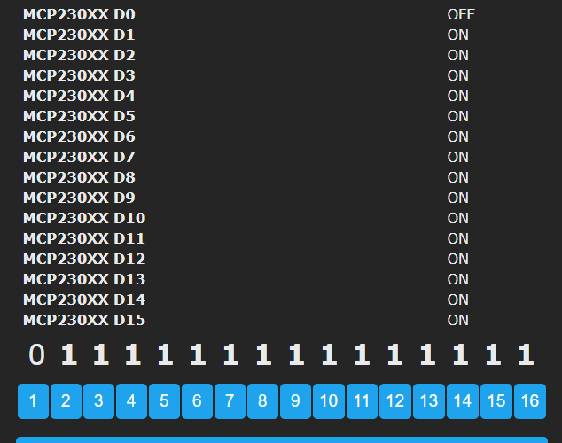
Then, in Home assistant, after discovery, it only identifies 8 relays(the ones you can rename on the web interface under the
'configure other').
I guess there is an issue tied to the limitation of 8 relays and the discovery of all outputs (as relays). All of them work fine under the web interface, but half appear as sensors in home assistant.
Isn't it the case for adding support for more relays when using a IO exp like the mcp23017?
 inominavell
on 22 Nov 2020
inominavell
on 22 Nov 2020
I guess there is an issue tied to the limitation of 8 relays and the discovery of all outputs (as relays).
Sorry, no. It is related to https://github.com/arendst/Tasmota/issues/5007
ascillato
on 22 Nov 2020
Related issues
 garret
·
3Comments
garret
·
3Comments
 smadds
·
3Comments
smadds
·
3Comments
 Ndrinta
·
3Comments
Ndrinta
·
3Comments
 esp32x
·
3Comments
esp32x
·
3Comments
 j4k3
·
3Comments
j4k3
·
3Comments