Tasmota: switching by main power frequency recognition
Hi all,
There are several new mini consoled switches similar to Shelly 2.5
All types based on 8266 (LM1 or TYWE3S)
Like shelly the dual switches triggered using live power by the standard mechanical switch.
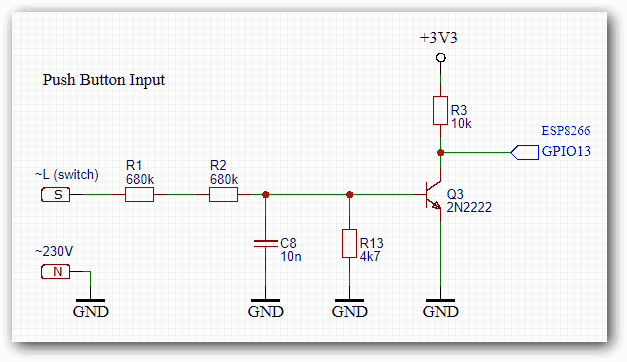
If turning on the switch, as a result the GPIO input state chances from 3V3 DC to 1.5AC(50 or 60HZ depending the main frequency).
Seems it can sense the main power frequency if the switch turned on.
I did try all options in the latest tasmota, but look like the current switch’s configuration doesn’t support the new mini switches.
Is it possible to add new configuration to Tasmota enabling triggering by frequency recognition?
The ESP also connected to one GPIO which receiving the constant reference 1.5AC. maybe the switch IO can be compared with the reference IO, and if equal -> switch is turned on.
 beenes
All 126 comments
Please, address this to the Tasmota Support Chat. The chat is a better and more dynamic channel for helping you. Github issues are meant for Tasmota Software Bug Reporting.
Please check the Contributing Guideline and Policy and the Support Guide.
Thanks.
Support Information
See Wiki for more information.
See Chat for more user experience.
See Community for forum.
See Code of Conduct
 Jason2866
on 13 Jul 2019
Jason2866
on 13 Jul 2019
Summary of discord:
they count 50Hz/60Hz pulses - needed hardware is already there
you can do this with Counter and Rule, but in fact, it's not a satisfactory solution.
same problem for that dimmer and even more:
https://github.com/arendst/Sonoff-Tasmota/issues/5737#issuecomment-507675241

I really hope there will be a solution,
maybe @chaosmaster @thirug010 @digiblur ... can help us, plzzzzz :)
no similarity to the Shelly SW / S1 / S2... inputs.
define a Counter at that input in Tasmota and see what is happening,
when the switch is pressed. you'll see the pulses in TasmotaUIwhat we're talking about :smiley: ...
https://www.aliexpress.com/item/33012114855.html
https://www.aliexpress.com/item/33012242667.html
Jason2866: "If someone with programming skills knowing Tasmota well, have a interest to support this device maybe a PR is made....
So dont await anything."I don't think it's only a device specific feature,
but a general and good solution to detect mains switch inputs.
e.g. additional Tasmota switch config (triggered counter / predefined number of pulses)
would be great...
 thxthx0
on 13 Jul 2019
thxthx0
on 13 Jul 2019
Since Tasmota has a lot of tasks to do, counting AC frequency pulses is not possible.
Tasmota has already counter function. You can use it via rules. See wiki, commands and rules
Jason2866
on 13 Jul 2019
Perhaps not the task of counting AC frequency, but a task of pulse assignment.
"not possible" ... words that coders don't know :)
edit some pics for the template repo:
QS-WIFI-D01 Dimmer 150W


thxthx0
on 13 Jul 2019
Just do it and make a PR ;-)
Jason2866
on 13 Jul 2019
Hi, there is no rule triggers for counters. By now, counters can be checked only every teleperiod time with the teleperiod message (using on counter#c1 do ... )
If adding a new trigger for counters like:
On counter1#state do power1 toggle endon
will not work either for that usecase due it will be toggling every 50ms while the switch is being pressed.
A proper solution for that should be a new gpio definition that supports frequency and have a switchdebounce feature.
At this moment I don't have that device in order to implement that. Sorry.
 ascillato
on 13 Jul 2019
ascillato
on 13 Jul 2019
@thxthx0
Can you post the picture of the circuit if possible
 thirug010
on 13 Jul 2019
thirug010
on 13 Jul 2019
yes of course.


beenes
on 13 Jul 2019
@ascillato and @thirug010 BIG, BIG thanks for your help :) highly appreciated.
@thirug010
I only have the dimmer module (issue #5737), but I think the input is the same.
That's what I found out (also most other parts if needed)
thxthx0
on 13 Jul 2019
If adding a new trigger for counters like:
On counter1#state do power1 toggle endonwill not work either for that usecase due it will be toggling every 50ms while the switch is being pressed.
@ascillato
I've tried @gemu2015's Script interpreter, where it is possible to set a trigger
input=COUNTER#C1
if chg[input]>0 then ...
but in fact, as you mentioned, there is the problem of repeated toggling.
I guess the exact number of pulses isn't relevant / 50 or 60Hz input voltage doesn't matter,
and may work like this:
Are there pulses at the input?
yes -> push button/switch is pressed
no -> button is not pressed
for the
- WiFi Switch:
if there is a short period of pulses (e.g. < 1 second) -> then toggle the relay
WiFi Dimmer:
if there is a short period of pulses -> then toggle the light
(if light is on ->SerialSend '0x00' / if light is off ->SerialSend previous value )if there starts a longer period of pulses -> toggle dim direction and then
increase/decrease dim value as long as the button is pressed
(and the limits aren't reached)...
thxthx0
on 14 Jul 2019
if you accept a one second delay the following script should work
>D
sw=0
cnt=0
toggle=0
>T
cnt=COUNTER#C1
>S
if chg[cnt]
then
; counter has changed, switch is on
sw=1
else
; no change switch is off
sw=0
endif
; set power according to switch
if chg[sw]>0
then
;=>power1 %sw%
toggle^=1
endif
if chg[toggle]>0
then
=>power1 %toggle%
endif
 gemu2015
on 14 Jul 2019
gemu2015
on 14 Jul 2019
Many thanks @gemu2015 for the script and of course especially for
your great Tasmota Script editor :thumbsup: :thumbsup: :thumbsup:
Yes, I also think the max. 1sec delay wouldn't be a problem at all.
Your script seems to work for switch (not pushbutton),
but if the switch remains in one position, there is also the problem with repeated toggling.
It seems for that reason I'm not able to write a script for the dimmer with 'soft' dimming.
thxthx0
on 15 Jul 2019
i edited the script above for toggling power
i don't think repeated toggling should be a problem.
dimming would better be done with 2 gpios
gemu2015
on 15 Jul 2019
BIG thanks again!
I think that has to be changed:
; set power according to switch
if chg[sw]>0
to
; set power according to switch
if sw>0
Yes, two GPIOs would be a solution (as other dimmers do),
but this WiFI Dimmer doesn't provide it and works flawless with orig. firmware.
your script for dimmer test (only light on/off) :
```
D
sw=0
cnt=0
toggle=0
B
=>print "WiFi Dimmer Script Test"
=>Baudrate 9600
T
cnt=COUNTER#C1
S
if chg[cnt]>0
then
; counter has changed, switch is on
sw=1
else
; no change switch is off
sw=0
endif
; set power according to switch
if sw>0
then
;=>power1 %sw%
toggle^=1
endif
if chg[toggle]>0
then
;=>power1 %toggle%
=#light
endif
light
if toggle==0
then
=>SerialSend5 FF550005DC0A
else
=>SerialSend5 FF55FF05DC0A
endif
thxthx0
on 15 Jul 2019
in the next release of scripter i introduce an F section which executes every 100ms
with this option i did a one button dimmer (via websend)
you may adapt this to your hardware
pr coming soon
; expand strings to hold websend
>D 25
sw=0
ws="websend [192.168.178.86]"
timer=0
hold=0
toggle=0
>B
; gpio 5 button input
spinm(5,0)
; fast section 100ms
>F
sw=pin[5]
; 100 ms timer
timer+=1
; 3 seconds long press
; below 0,5 short press
if sw==0
and timer>5
and timer<30
then
; short press
;=>print short press
toggle^=1
=>%ws% power1 %toggle%
endif
if sw>0
then
;pressed
if timer>30
then
; hold
hold=1
;=>print hold=%timer%
if toggle>0
then
=>%ws% dimmer +
else
=>%ws% dimmer -
endif
endif
else
timer=0
hold=0
endif
gemu2015
on 16 Jul 2019
did a pr with the new features.
since teleperiod counter messages were to slow i also added access to the irq driven pulse counter
val=pc[x] which updates immediately.
gemu2015
on 16 Jul 2019
Perfect! Thanks so much @gemu2015
I'm looking forward to testing and will reply...
thxthx0
on 16 Jul 2019
WoW what should I say - it WORKS :thumbsup: Awesome!!!!!!
No more limits (well, obviously my scripting skills are,
but I'm trying to get that Wifi Dimmer under control :smile: )
MANY, MANY thanks @gemu2015
@beenes the following script should do the job for your 2-Gang Wifi Switch
(similar to https://www.aliexpress.com/item/33050766518.html?spm=2114)
>D
sw1=0
sw2=0
cnt1=0
cnt2=0
timer1=0
timer2=0
toggle1=0
toggle2=0

>B
=>print "WiFi 2-Gang Switch Script"

>F
; Counter1/2 and Relay1/2 configured in template
cnt1=pc[1]
cnt2=pc[2]

if chg[cnt1]>0
then
; counter1 has changed, switch is on
sw1=1
else
; no change switch is off
sw1=0
endif

if chg[cnt2]>0
then
; counter2 has changed, switch is on
sw2=1
else
; no change switch is off
sw2=0
endif

; 100 ms timer
timer1+=1
timer2+=1

if sw1==0
and timer1>2
and timer1<30
then
;=>print short press1
toggle1^=1
=>Power1 %toggle1%
endif

if sw1==0
then
timer1=0
endif

if sw2==0
and timer2>2
and timer2<30
then
;=>print short press2
toggle2^=1
=>Power2 %toggle2%
endif

if sw2==0
then
timer2=0
endif
Thanks guys,
Sorry @thxthx0 for my clueless question, but at the moment I have no idea how to use this script code.
Definitely would like to learn. Is there a tutorial for this?
beenes
on 19 Jul 2019
 meingraham
on 19 Jul 2019
meingraham
on 19 Jul 2019
So perhaps dimming control would be something roughly like the below? (very quick and largely missing any detail...)
`;Long press....
if timer>30
then
; held for > 3 seconds - start dimming
hold=1
;=>print held for=%timer%
if toggle>0
then
    <increment dimmer variable as hex string>
    =>SerialSend5 FF55 <dimmer> 05DC0A
else
    <decrement dimmer variable as hex string>
    =>SerialSend5 FF55 <dimmer> 05DC0A
endif
endif
;Short press...
if toggle==0
then
=>SerialSend5 FF550005DC0A
else
=>SerialSend5 FF55
endif
`
 dbrb2
on 19 Jul 2019
dbrb2
on 19 Jul 2019
@meingraham , @thxthx0 thanks for the script tutorial.
which files in the release version controlling the switch configuration?
the mention @thxthx0's script need to be added in a specific file before compilation?
beenes
on 19 Jul 2019
You enter the script at runtime with the device online. The script is not "compiled in". This is the same as Tasmota rules.
Third line in the scripting documentation:
In submenu Configuration => edit script
Develop your script in a file and paste it into the console. Then, if you have to reset the device, you'll have the script backed up.
Mike
meingraham
on 19 Jul 2019
and you have to compile recent Tasmota dev version with enabled Scripts @beenes
//#define USE_RULES
#define USE_SCRIPT

thxthx0
on 19 Jul 2019
@dbrb2
I've already managed to write a working Dimmer script :)
with almost all functions of the original firmware.
one thing still missing -> a dimmer slider
@gemu2015 You got any tips for me?? :)
is there anything like pc[x] ... to read Tasmota PWM "Dimmer" value or another solution...
thxthx0
on 19 Jul 2019
@thxthx0
you have to define a fake pwm channel in tasmota on an unused pin
you will get a slider and an on/off button then
in section >E you will get the event for this power and dimmer values
dimmer=Dimmer
power=pwr[x]
according to a tutorial for scripter:
i have been told to be a bad teacher for beginners.
would be nice if someone with better skills in this field would write one
i would certainly help if needed
gemu2015
on 20 Jul 2019
Oh cool @thxthx0 would you be happy to share it?
dbrb2
on 20 Jul 2019
@thxthx0 It would be highly appreciated if you add your findings to this devices in a new template.
I know it is NOT a template. ALL devices are expained there. It is the place where user search...
Thx
Jason2866
on 20 Jul 2019
@gemu2015
Thanks man :thumbsup: I didn't get it,
maybe sometimes the fault of the teacher, mostly of the lazy student ;))
@dbrb2
Of course - let me do a few more tests and maybe some changes, then I'll post it soon.
@Jason2866
Yes, I will try it (never done it before) once there is feedback that it works.
thxthx0
on 20 Jul 2019
The device can be added as a "miscellaneous" type in the templates repository. Since the device is an ESP device with Tasmota loaded and has certain components assigned to GPIO (real and phantom), then a template is actually in order.
In addition, information on the frequency detection circuit (i.e., the schematic above), how to connect it, the script (with copious comments) can be part of the "flashing" guide of the template.
The detailed "flashing guide" is probably best added in a second step. First create a new template in the repository with "basic" information in the notes field. After the template is merged into the repository, you can edit it (there is an "Edit on GitHub" link on the template's page) and add the details using the full markdown syntax and create a pull request to have these details merged onto the template page.
Cheers!
Mike
meingraham
on 20 Jul 2019
@meingraham is there any way to enable the script option?
at the moment i don't have the edit script option in my submenu.
beenes
on 21 Jul 2019
@beenes https://github.com/arendst/Sonoff-Tasmota/issues/6085#issuecomment-513204013
meingraham
on 21 Jul 2019
or @beenes https://github.com/arendst/Sonoff-Tasmota/issues/6085#issuecomment-513369748 ;)
@meingraham
thanks, yes, I also think there is a lot of information here and under #5737
so two steps is a good idea.
I think it would also fit under "Switches and Dimmers" in the templates repository.
thxthx0
on 21 Jul 2019
Hi, Script and config to test:
WiFi-Dimmer-Script-v0.3.txt
for Wifi Smart Dimmer Module 220V-240V 150W
e.g. https://www.aliexpress.com/item/33010332202.html?spm=2114

(Wi-Fi Dimmer Smart Life/Tuya APP MoesHouse and many other sellers)
recent Tasmota dev version with enabled Scripts is needed:
https://github.com/arendst/Sonoff-Tasmota/tree/development
#undef USE_RULES
#define USE_SCRIPT
Generic config:
GPIO1 -> Serial Tx (148)
GPIO3 -> Serial Rx (149)
GPIO13 -> Counter1 (42)
GPIO14 -> PWM1 (37) (or any unused GPIO)
or Template:
{"NAME":"WiFi Dimmer","GPIO":[0,148,0,149,0,0,0,0,0,42,37,0,0],"FLAG":0,"BASE":18}
edit: Script Update
v0.2: FIX infinite loop (HA with SetOption19 1 and slider at min)
v0.3: FIX obsolete code / comments / space
thxthx0
on 22 Jul 2019
@thxthx0
When you create the entry in the templates repository, please call the device MoesHouse MS-105 Wi-Fi Dimmer
meingraham
on 22 Jul 2019
Does this dimmer has Zero Cross Detection? Or is it a classic Triac dimmer?
Jason2866
on 23 Jul 2019
@Jason2866
It's a Trailing-Edge Phase Dimmer and yes, has
Zero Crossing Detection done by STM8S003F3 MCU

Although there is the misleading module name
QS-WIFI-D01-TRIAC in the instruction manual,
it is definitely Power MOSFET driven (SVF12N65F)
for dimmable LED light bulbs / dimmable power supplies...
In my opinion the quality is high and there are many
sellers who already offer it e.g. at Ali, Amazon...
registered shipping from China only took about 10 days.
So maybe worth a try before Shelly presents a clone 😄
thxthx0
on 23 Jul 2019
@thxthx0 Interesting, it seems similar in hardware design as the Tuya Touch Dimmer which also uses an STM8S to handle zero-crossing detection but uses the tuya-protocol to communicate with the ESP.
I have actually written a replacement-firmware for the MCU some time ago:
https://github.com/chaosmaster/tuya_mcu/tree/master/stm8_tuya
Also seems to use the same pin for zero-crossing:
https://github.com/chaosmaster/tuya_mcu/blob/master/stm8_tuya/src/gpio.h#L21
 chaosmaster
on 23 Jul 2019
chaosmaster
on 23 Jul 2019
@chaosmaster
Would be GREAT, if you could write a replacement FW here, too.
I'm not familiar with STM8 MCUs, but the orig. FW seems to be protected.
The PWM output for dimming is PC3 (Pin 13) @ STM8S003F3 MCU
and the serial protocol is very simple, only one command with changing dim values.
thxthx0
on 23 Jul 2019
@thxthx0 The Tuya touch uses PC7 for the PWM.
I never really proceeded with the project, as i was hitting size constraints with using SDCC.
I reverted back to using the original firmware that was on the MCU, but it does mostly work.
I had actually planned to make the zero-crossing also available as a mains-distribution-frequency sensor to Tasmota, as it could give interesting insights in the distribution network.
I also haven't worked with STM8 before or after this.
I'm sure it could be easily modified to work with your dimmer.
chaosmaster
on 23 Jul 2019
@thxthx0
Did you create an entry in the template repository? If so, did you include the frequency detection circuit and an explanation of what it does, why it's needed, and what you're doing with it?
I have created a new article for the Scripter and a Cookbook to go along with that. I pulled several examples that @gemu2015 and users have posted.
https://github.com/arendst/Sonoff-Tasmota/wiki/Tasmota-Scripting-Language
https://github.com/arendst/Sonoff-Tasmota/wiki/Script-Cookbook
Can you provide an abstract of what your script does; why it's required? I can add your script to the Cookbook but I'd like put an explanation with it.
Thanks!
Mike
meingraham
on 29 Jul 2019
@meingraham
I took the first step last week, but no detailed explanations yet:
https://blakadder.github.io/templates/qs-wifi_D01_dimmer.html
Spent some time finding a suitable name,
maybe Moes or MoesHouse in front would be a better choice, as you suggested.
Yes, I'll provide more explanations for the template repository and
the Cookbook (not only the short comments in the script due max script size),
but there still seem to be some issues with Alexa, HA, Domoticz...
thxthx0
on 29 Jul 2019
Are there any binaries available with scripting already enabled (I realise that sounds very lazy!)
dbrb2
on 29 Jul 2019
I don't think so, you may use Gitpod
https://gitpod.io/#https://github.com/benzino77/tasmocompiler
with "Custom parameters"
#undef USE_RULES
#define USE_SCRIPT
thxthx0
on 29 Jul 2019
There are no plans to provide pre-compiled binaries with Scripting enabled. As suggested, Gitpod makes it super easy to get binaries for "special" use cases. You can still OTA, but you have to do it via file upload instead of pointing the web OTA to thehackbox. Still super easy. The only thing to be aware of with file upload is that you will have to perform the intermediate minimal upload yourself in order to make room for the final binary if the binary is larger than 502KB.
We have added the scripting feature to the wiki so it's easier to find information. It's in its early stages so much to be enhanced in terms of details... such as how to compile, upload, etc. But now that it's in the wiki, the user community (i.e., you guys) can start contributing your knowledge and experiences.
Cheers!
Mike
meingraham
on 29 Jul 2019
Hello! I will continue https://github.com/arendst/Sonoff-Tasmota/issues/5737#issuecomment-515796060 here. I found the bug in the script and fixed it. "Insert code" is not working very good with scripts so I will paste a link WiFi-Dimmer-Script-v0.2.txt
 ondoteam
on 29 Jul 2019
ondoteam
on 29 Jul 2019
THX @ondoteam
txt updated above
thxthx0
on 29 Jul 2019
I compiled 6.6.0.3 and enabled the above script after flashing by soldering all wires to the module (with RE and GPIO0 at GND). Working a treat thank you except the switch (momentary) connected to 'S' is not working. Is there a trick to that?
FYI, the slider also seems to set full brightness at around 30~35% in my instance so managing brightness levels is quite twitchy.
 xbmcnut
on 30 Jul 2019
xbmcnut
on 30 Jul 2019
@xbmcnut hello! Did you restart the device after save the script? If not, just try. By the way double check the script, because sometimes the devices just restart when you tap "Save" button due to an exception and do not save anything.
About the slider: it is working for me, but I am using HA not Tasmota. By the way I tested it yesterday using the Tasmota WebUI and it works... the issue is from OFF to ON using the slider?
Sorry about my english :see_no_evil:
ondoteam
on 30 Jul 2019
@ondoteam Yes, hard reset after flashing. I've gone back into script editor and the V2 text is still there so assuming it stuck. Switch was working on stock firmware but as I'm new to Platformio, I'll double check my settings there but if scripts are available, I assume I got it right?
xbmcnut
on 30 Jul 2019
@xbmcnut I mean "Restart" (red button in Tasmota WebUI) after press "Save" button in "Configuration > Edit script".
ondoteam
on 30 Jul 2019
@ondoteam Hold the phone!
I compiled with the 2.4.2 core using https://gitpod.io/#https://github.com/benzino77/tasmocompiler instead of Platformio and it works!! I must have screwed something somewhere. Gitpod makes it so easy.
xbmcnut
on 31 Jul 2019
@meingraham
Template Repo has been updated now:
Moes QS-WiFi-D01 Dimmer 150W
Please feel free to make corrections,
and if there are too few details, I will add them.
Some format errors I'll fix with the next changes.
thxthx0
on 1 Aug 2019
@thxthx0
Great entry!
I did some re-arranging/re-formatting. You'll have to wait for my PR to be merged before reviewing. Let me know if I screwed anything up... and take corrective action to edit as needed :wink:
Mike
meingraham
on 1 Aug 2019
Thanks a lot! :thumbsup: @meingraham
thxthx0
on 2 Aug 2019
@beenes
Has this community effort provided the solution you needed? If so, please close this issue. If not, what symptoms are you encountering?
Mike
meingraham
on 2 Aug 2019
Before this thread gets closed :),
there's still an issue that dimming does not work with Alexa and the script.
my test config:
Tasmota 6.6.0.3 with Hue Emulation
Echo Dot 2nd gen
everything works fine
- on/off and dimming via slider, button, MQTT, http
- on/off with Alexa
but not dimming with Alexa (e.g. "Alexa, light to 80")
- although the "Dimmer" value and the slider are set accordingly,
console message:
MQT: stat/light/RESULT = {"POWER":"ON","Dimmer":80} - the script seems not to be triggered
maybe @gemu2015 would you be so kind to look at the script above
https://github.com/arendst/Sonoff-Tasmota/files/3444155/WiFi-Dimmer-Script-v0.2.txt
and what could be the error in >E ❔
thxthx0
on 4 Aug 2019
@thxthx0
Try adding some debug print statements to see if the script starts at all?
=> print prints to info log for debugging
and set logging levels for more information - loglvl = loglevel of script cmds
meingraham
on 4 Aug 2019
@thxthx0
MQTT RESULT calls the E section, you should get an update there.
try the following code in E to debug
slider=Dimmer
power=POWER
if upd[slider]>0
then
=>print slider updated %slider%
endif
if upd[power]>0
then
=>print power updated %power%
endif
gemu2015
on 4 Aug 2019
@thxthx0
in case dimmer doesn't call E insert the following code in file xdrv_20_hue.ino
identify the following lines
LightPreparePower();
if (LST_COLDWARM <= light_subtype) {
MqttPublishPrefixTopic_P(RESULT_OR_STAT, PSTR(D_CMND_COLOR));
} else {
MqttPublishPrefixTopic_P(RESULT_OR_STAT, PSTR(D_CMND_DIMMER));
}
and insert this code =>XdrvRulesProcess(); in the next line
gemu2015
on 4 Aug 2019
@gemu2015 Thanks for the update. I'm not familiar with how rules get triggered. Maybe there are other locations in the Hue/Wemo emulation that does not trigger rules.
Are you doing the PR? Or do you want me to do it?
 s-hadinger
on 4 Aug 2019
s-hadinger
on 4 Aug 2019
@s-hadinger
i think this should solve the problem, lets wait for @thxthx0 report
and than it would be nice if you do a pr.
gemu2015
on 4 Aug 2019
YES :)), it's solved with XdrvRulesProcess(); in xdrv_20_hue.ino
My highest respect to you @gemu2015
Vielen, vielen DANK!
and thx thx thx thx thx thx thx thx thx thx...
to all devs here :thumbsup:
thxthx0
on 4 Aug 2019
@s-hadinger I'll add it now. There is only one location where it can be functional as it needs MqttPublish data for processing.
So the suggested location is fine.
 arendst
on 4 Aug 2019
arendst
on 4 Aug 2019
Thanks @arendst and @gemu2015
s-hadinger
on 4 Aug 2019
I use this device with (toggle) mains switches. So another state of the switch should toggle the relay on or off. I used this script:
D
sw1=0
sw2=0
sw3=0
sw4=0
cnt1=0
cnt2=0
t1=0
t2=0
B
=>print "Moeshouse double switch"
F
cnt1=pc[1]
if chg[cnt1]>0
then
t1=1
else
t1=0
endif
if t1==1
then
if sw1==0
then
=>Power1 toggle
sw1=1
sw2=0
endif
endif
if t1==0
then
if sw2==0
then
=>Power1 toggle
sw2=1
sw1=0
endif
endif
cnt2=pc[2]
if chg[cnt2]>0
then
t2=1
else
t2=0
endif
if t2==1
then
if sw3==0
then
=>Power2 toggle
sw3=1
sw4=0
endif
endif
if t2==0
then
if sw4==0
then
=>Power2 toggle
sw4=1
sw3=0
endif
endif
It is working fine but you'll have the counters on your webpage. Don't know if that matters
 Pheerink
on 16 Aug 2019
Pheerink
on 16 Aug 2019
@Pheerink
there is also a script for the 2-gang switch above,
you could test it please (works with short press):
https://github.com/arendst/Sonoff-Tasmota/issues/6085#issuecomment-512353010
counters on the webpage:
maybe @arendst
would it be possible to get a SetOption to hide the counters in the WebUI?
THX
thxthx0
on 16 Aug 2019
I'll work on a more general way to hide specific items from the webGui. Give me some days.
arendst
on 16 Aug 2019
@thxthx0 Yes that is working perfectly. But I don't use momentary switches in my home to put on the lights manually. So that's why I changed the script.
BTW the relays are bouncing sometimes. Need to figure out if I can build in a delay? The bouncing occurs also via the WebUi. Very strange.
Pheerink
on 16 Aug 2019
arendst Perfect idea, would be great !
Pheerink
on 16 Aug 2019
With the latest dev version 6.6.0.5 you get a new command WebSensor<sensor number> 0/1 to control the web gui display of sensor data.
In case of counter data this is sensor 1 related to the sensor file name xsns_01_counter.ino.
So command WebSensor1 off should stop displaying counter data on the gui.
arendst
on 16 Aug 2019
What a service. You're the best!
Pheerink
on 16 Aug 2019
@arendst
Websensor
meingraham
on 16 Aug 2019
As I tried to explain, by filename. The only known relation between this command index and a sensor is the unique id within the sensor file. This Id equals the number in the sensor file name.
So for xdrv_01_counter.ino the index is 1. For energy sensor info the index is 3 to make you wonder...
arendst
on 16 Aug 2019
See latest update where command status 4 returns all sensors enabled in the specific firmware.
See below as an example of my firmware images:
..."Sensors":[2,3,4,5,8,9,10,14,15,17,18,34]
The numbers equal the xsns_ filename number.
arendst
on 16 Aug 2019
Ah, it's by sensor type. If you have multiples of the same sensor type, it controls the display of all of them.
meingraham
on 16 Aug 2019
Correct. Otherwise the addition in code size would be to large.
arendst
on 16 Aug 2019
@arendst
So, the sensor number corresponds to the numbers in the sns section of this spreadsheet (created by @mike2nl). In addition, all of the nrg sensors are covered by 3 (the reason it's missing in the sns enumeration).
Yes?
meingraham
on 16 Aug 2019
Correct.
arendst
on 16 Aug 2019
This issue has been automatically marked as stale because it has not had recent activity. It will be closed if no further activity occurs. Thank you for your contributions.
![stale[bot] picture](https://avatars3.githubusercontent.com/in/1724?v=4&s=40) stale[bot]
on 10 Sep 2019
stale[bot]
on 10 Sep 2019
I have modified the script to do something like switchmode1. Many people use that mode because you can use classic light switch with it. I'm ready to add 2 way 2 gang wifi switch to wiki but I think beenes has a priority to do that. @Beeenes will you do that?
>D
sw1=0
sw2=0
cnt1=0
cnt2=0
timer1=0
timer2=0
pwr1=0
pwr2=0


>B
=>print "WiFi 2-Gang Switch Script"


>F
; Counter1/2 and Relay1/2 configured in template
cnt1=pc[1]
cnt2=pc[2]

if chg[cnt1]>0
then
; counter1 has changed, switch is on, reset counter
sw1=1
->Counter1 0
else
; no change switch is off
sw1=0
endif

if chg[cnt2]>0
then
; counter2 has changed, switch is on, reset counter
sw2=1
->Counter2 0
else
; no change switch is off
sw2=0
endif

; 100 ms timer
timer1+=1
timer2+=1

if sw1==1
and timer1>2
and pwr1==0

then
=>Power1 1
pwr1=1
endif

if sw1==0
and timer1<=2
and pwr1==1

then
=>Power1 0
pwr1=0
endif

if sw1==0
then
timer1=0
endif

if sw2==1
and timer2>2
and pwr2==0
then
=>Power2 1
pwr2=1
endif

if sw2==0
and timer2<=2
and pwr2==1
then
=>Power2 0
pwr2=0
endif

if sw2==0
then
timer2=0
endif
 cHunter789
on 12 Sep 2019
cHunter789
on 12 Sep 2019
Very nice, thanks a lot. Can somebody please add the template (pin Config) for the wifi 2 Gang switch?
Thanks a lot.
 Markus-byte
on 19 Sep 2019
Markus-byte
on 19 Sep 2019
The template for wifi2 gang switch:
{"NAME":"moeshouse2wifi","GPIO":[0,0,17,0,160,0,0,0,43,42,21,22,0],"FLAG":0,"BASE":18}
cHunter789
on 19 Sep 2019
@cHunter789
It seems that @beenes is no longer replying here.
I think it would be great if you could write the entry for the 2-Gang Wifi Switch at the Template Repository,
with your template and script and maybe also with the script for push button control from above https://github.com/arendst/Sonoff-Tasmota/issues/6085#issuecomment-512353010
BTW Tuya Convert is working again 👍
https://github.com/ct-Open-Source/tuya-convert/issues/273
thxthx0
on 20 Sep 2019
I have written something in template database. Not so great as I should but have no time to do it better.
BTW: Have anyone working compilation with script and core 2.3.0? When I'm trying to use core 2.3.0 and script the device constantly restarting few times per minute. Cores 2.4.2 and 2.5.2 are working good but unfortunately not working good with my wifi...
cHunter789
on 20 Sep 2019
@cHunter789
It works without issues with Core 2.3.0 and the dimmer script for me.
I also tried your script - no restarts/exceptions,
but I don't have the 2-gang switch.
Maybe you should try Reset 5 or full erase esptool.py erase_flash and a clean new flash.
Or give Core Pre 2.6.x a try - it's default in the dev branch now,
but still not supported by benzino77's tasmocompile.
thxthx0
on 22 Sep 2019
Hello, I have just converted my 150W wifi dimmer with tuya convert and then flashed sonoff with scripting support. Unfortunately the switching by main power does not work. The Counter is incrementing when main power is connected to the S input, but it seems the ">F" loop ist never executed. For debugging I pasted a "=>print > Loop <" into the ">F" section, so there should be a log entry in console every 100ms, but that does not happen.
I have build with core 2.4.2
Building core 2.3.0 with USE_SCRIPT fails:
/workspace/Sonoff-Tasmota/sonoff/xdrv_10_scripter.ino: In function 'uint16_t GetStack()':
/workspace/Sonoff-Tasmota/sonoff/xdrv_10_scripter.ino:1616:21: error: 'g_pcont' was not declared in this scope
   return (4 * (sp - g_pcont.stack));
                     ^
/workspace/Sonoff-Tasmota/sonoff/xdrv_10_scripter.ino: In function 'void ScriptSaveSettings()':
/workspace/Sonoff-Tasmota/sonoff/xdrv_10_scripter.ino:2863:32: warning: deprecated conversion from string constant to 'char*' [-Wwrite-strings]
       SD.remove(FAT_SCRIPT_NAME);
                                ^
/workspace/Sonoff-Tasmota/sonoff/xdrv_10_scripter.ino: In function 'bool Xdrv10(uint8_t)':
/workspace/Sonoff-Tasmota/sonoff/xdrv_10_scripter.ino:2998:38: warning: deprecated conversion from string constant to 'char*' [-Wwrite-strings]
         if (SD.exists(FAT_SCRIPT_NAME)) {
Any ideas?
In the past I only used sonoff-basic and tried to build "sonoff-basic" with USE_COUNTER, but that does not work (no counter available). You have to build the target "sonoff" to have counter support. Maybe this information can be added to the template.
 nemesis03
on 24 Sep 2019
nemesis03
on 24 Sep 2019
@nemesis03 As the name suggests basic provides basic functions only ;-)
Scripter needs self compiling, doing this choosing sonoff.bin is always a good choice.
As described in wiki you can define what should be in your personal build version.
Dont expect that all new features will be possible with core 2.3.0. Core is to old and some new stuff is simply not possible with. Use core pre 2.6. Many fixes and better than 2.4.x and 2.5.x
Jason2866
on 24 Sep 2019
@cHunter789 and @thxthx0
Tasmocompile now supports core pre 2.6. too
Jason2866
on 24 Sep 2019
Looks like core 2.6. solved my problems with wifi and works the same stable as 2.3.0 :) 24h and there is no disconnections!
cHunter789
on 25 Sep 2019
This issue can be closed. Implemented; yes?
meingraham
on 5 Oct 2019
Sorry to dredge this thing up again.
Has anyone implemented the dimmer using a on/off toggle switch (NOT a momentary switch)?
I have a normal light switch on the wall, and want to have the physical switch toggle between off and dimval.
I have everything working via the web ui, except my physical on/off switch does nothing, even toggling it quickly or holding it in the on or off position does nothing.
I'm not too familiar with the scripting but seems the only thing I need to get right is the script. The counter counts up while my switch is in the on position, and stops counting when in the off position, so looks like I have the pin config, and the wiring all right.
I have done everything as per: https://blakadder.github.io/templates/qs-wifi_D01_dimmer.html
Thanks!
EDIT: Looking at the script above, seems like something did this for the 2 gang switch, but not the dimmer. I'm not exactly sure what I need to change for my setup.
 KiLLeRRaT
on 9 Oct 2019
KiLLeRRaT
on 9 Oct 2019
I dont think it is possible, how do you know when to dimm and when to switch?
The input is always triggered when switch is in on position.
Jason2866
on 9 Oct 2019
@Jason2866 I don't mind about dimming using the physical switch. I just want the physical switch to either turn it off or on. That's how the switch currently works without the dimmer.
Surely should be able to do this with the script? Instead of the short/long press, just toggle it on any press and release.
I just need to figure out the syntax and also, my F section doesn't seem to do antyhing, as I don't see any logging I add in there. (I have tried 2.4.2, 2.5.2, and pre, all same outcome.
KiLLeRRaT
on 9 Oct 2019
@KiLLeRRaT
yes, with changes and simplification in the script the dimmer runs with toggle switch operation (without dimming).
But for a test the dimmer script also works with a toggle switch, if the switch is held in one position.
If your >F section doesn't do anything, you may have overlooked this in the Template Repo:
To use the script, you have to compile Tasmota (v6.6.0.3 or higher) with Scripting enabled.
6.6.0.3 Tasmota Dev Version or higher is required.
By the way, most toggle switches can simply be converted into momentary / push buttons with a small compression spring - for full dim operation.
thxthx0
on 9 Oct 2019
Heh I've tried, most everything I can at this stage.
My pio environment with core pre, or 2.5.2 won't compile. It only compiles on 2.4.2.
I just did a pull of the current master branch.
I know that scripting is working, because under the B section, there is a log entry =>print > WiFi-Dimmer-Script-v0.3 < and that does appear in my console as it should.
Just the F section not working. I've even reduced my F section down to only
>F
=>print > Hello World <
Still nothing being logged. Am I missing anything else?
I have actually just changed my script to
>D
=>print > Hello World1 <

>B
=>print > Hello World2 <

>F
=>print > Hello World3 <

>E
=>print > Hello World4 <
I then restarted the device. The only things being printed out is Hello World4, followed by Hello World2
EDIT: I managed to get core 2.5.2 compiling, but still the F section doesn't run or output any logging.
KiLLeRRaT
on 10 Oct 2019
master branch is v6.6.0
an has not included the code for >F section in scripting.
so again: 6.6.0.3 Tasmota Dev Version or higher is required.
you can use GitPod to compile, as suggested in the repo.
it takes a few seconds:
Tasmota-dev-6.6.0.17-w-Scripting-2.6.x-1MB.zip
thxthx0
on 10 Oct 2019
Hi @thxthx0,
Thanks very much for flicking that through. That works exactly as intended.
I totally missed the changelog file, and assumed (silly me) that 6.6.0 would contain all the features since 6.6.0.x releases would just contain bug fixes
I will jump into the dev branch, clean my machine, and see if I can get it going.
Thanks again for the help :)
EDIT: I tried the script straight off of: https://blakadder.github.io/templates/qs-wifi_D01_dimmer.html and that didn't work. I discovered that on the >F section, there is an extra space character, >F<SPACE>. Once I remove that, it works. Just a note for future people struggling.
I have also now successfully built using the latest dev version, enabled scripting, and everything is working. I will post here one last time once I have a script that works for toggle switches so that people in the same situation can find it here.
KiLLeRRaT
on 10 Oct 2019
Here you go, looks like this works as it should using a toggle switch instead of a momentary switch:
WiFi-Dimmer-Script-v0.3 - Dimmer with toggle switch.txt
EDIT: Hmm this doesn't quite work when you turn the switch on/off using MQTT.
EDIT2: I think I got it now! Works via MQTT and the toggle in any order.
KiLLeRRaT
on 10 Oct 2019
Hey, hoping this question is relavant since i couldn't understand it on my own.
i hope a physical rotary dimmer.
is this module can be connected to the rotary and work together? not sure what should i need to change in the script for it to work.
(already tested with toggle switch and works fine)
 saarsinai
on 19 Oct 2019
saarsinai
on 19 Oct 2019
Hi @thxthx0,
I am beginner. Thanks for placing the compiled firmware here. I wouldn't be able to do it alone without it. I think it would be a good idea to put this ready firmware on the project page - for those like me, it's invaluable help. Thanks again for the work you are doing here. Greetings to all creators. Super Tasmota and Moes dimmer projects!
 kurczak2
on 21 Oct 2019
kurczak2
on 21 Oct 2019
I can't get this to work, my light (LED) does not turn on, however the "ON" "OFF" in the web-interface changes as I press the physical switch or if I toggle it on the inferface itself... but the output on the dimmer is still OFF... when using the original firmware, the dimmer did toogle the light and dimm it so the hardware was working before in flashed the Tasmota FW. I used the precompiled .bin file "Tasmota-v7.0.0.1-w-Scripting-2.6.x-1MB.zip" found here https://blakadder.github.io/templates/qs-wifi_D01_dimmer.html and followed all the instructions as far as I know :/ any clue what might be the problem? do I maybe have to compile my own Tasmota? or should it work using the precompiled file?
 FPVs8
on 30 Oct 2019
FPVs8
on 30 Oct 2019
Hi @FPVs8
yes, it should work with the precompiled binary as it does for me.
Maybe try Reset 5 and check all connections,
and whether you copied the entire script and pasted it correctly.
thxthx0
on 30 Oct 2019
thanks for the quick reply @thxthx0 I have checked everything multiple times now... and I ended up with opening the dimmer case and after inspection with the magnifying glass I found a bad solder joint... I fixed that and now everything works! thanks for all the hard work, figuring out how to code the script etc. and making this all so simple for us, now I am going to get more of these dimmers :D
FPVs8
on 31 Oct 2019
Just a quick note:
I tried to flash the unit using the .zip image and using tuya-convert
However, I missed the warning that the initial image to be flashed when using tuya-convert has to be less than 512k, and this image is about 570k
That being the case, I am pretty certain I have bricked my device....
Entirely my fault, but worth bearing in mind if anyone else tries to use the tuya-convert OTA flash method
dbrb2
on 6 Nov 2019
I have flashed one device with no problems. Another has flashed, and seems to have taken fine - however the lights always slightly on - and any attempt to toggle them, or change their brightness, causes the Tasmota device to crash until it is restarted....
Any ideas? It sounds like some issue with the serial comms...however the unit was working OK with Tuya firmware initially.
dbrb2
on 6 Nov 2019
I have heard a couple of people say that the cause of the lights staying on
was a faulty device. They exchanged the device and was fine thereafter. I
haven't experienced this first hand though.
On Thu, Nov 7, 2019 at 11:47 AM dbrb2 notifications@github.com wrote:
I have flashed one device with no problems. Another has flashed, and seems
to have taken fine - however the lights always slightly on - and any
attempt to toggle them, or change their brightness, causes the Tasmota
device to crash until it is restarted....Any ideas? It sounds like some issue with the serial comms...?
—
You are receiving this because you were mentioned.
Reply to this email directly, view it on GitHub
https://github.com/arendst/Tasmota/issues/6085?email_source=notifications&email_token=ABWCPVAR6MZDUC43OVIXISDQSNCQDA5CNFSM4ICYXKW2YY3PNVWWK3TUL52HS4DFVREXG43VMVBW63LNMVXHJKTDN5WW2ZLOORPWSZGOEDIIGVQ#issuecomment-550536022,
or unsubscribe
https://github.com/notifications/unsubscribe-auth/ABWCPVFOYQQ46XCI23JOCYTQSNCQDANCNFSM4ICYXKWQ
.
--
Albert Gouws
KiLLeRRaT
on 7 Nov 2019
I now have ~13 units working reliably. One thing I have noticed is the reported load average of the units seems to be reported reliably as in the high hundreds, but only when the device is on...Is this down to the overhead of running the script...?
The devices seem to function fine...
dbrb2
on 8 Nov 2019
The WiFi-Dimmer-Script-v0.3 works perfect - thank you!
Is there any way that the light can be turned on with the brightens set to 100% when triggered with the toggle switch regardless of its previous state?
 alrumbles
on 24 Nov 2019
alrumbles
on 24 Nov 2019
brightens set to 100% when triggered with the toggle switch regardless of its previous state
Hi, yes, change line 48 from
=#senddim(dimval)
to
=#senddim(100)
or
=#senddim(dimul)
thxthx0
on 24 Nov 2019
Worked a treat! Thank you
alrumbles
on 24 Nov 2019
my test device (a 2 Gang 2 Weg ex MOES-House Modul) was runing now for... dunno... 2 Weeks or longer..
However, i had one switch "on" to let the counter count and today i heard the Relay switching like crazy. So i just want to tell you if you have stange switching issues: set the counter to 0 or add some lines in the script.
 onkeldittmayer
on 25 Nov 2019
onkeldittmayer
on 25 Nov 2019
my test device (a 2 Gang 2 Weg ex MOES-House Modul) was runing now for... dunno... 2 Weeks or longer..
However, i had one switch "on" to let the counter count and today i heard the Relay switching like crazy. So i just want to tell you if you have stange switching issues: set the counter to 0 or add some lines in the script.
THX for the info, updated script for 2way 2gang
>D
sw1=0
sw2=0
cnt1=0
cnt2=0
timer1=0
timer2=0
pwr1=0
pwr2=0
pwr1save=0
pwr2save=0

>B
=>print "WiFi 2-Gang Switch Script"


>F
; Counter1/2 and Relay1/2 configured in template
cnt1=pc[1]
cnt2=pc[2]

if chg[cnt1]>0
then
; counter1 has changed, switch is on, reset counter
sw1=1
else
; no change switch is off
sw1=0
endif

if chg[cnt2]>0
then
; counter2 has changed, switch is on,
sw2=1
else
; no change switch is off
sw2=0
endif

; 100 ms timer
timer1+=1
timer2+=1

if sw1==1
and timer1>2
and pwr1==0

then
=>Power1 1
pwr1=1
endif

if sw1==0
and timer1<=2
and pwr1==1

then
=>Power1 0
pwr1=0
endif

if sw1==0
then
timer1=0
endif

if sw2==1
and timer2>2
and pwr2==0
then
=>Power2 1
pwr2=1
endif

if sw2==0
and timer2<=2
and pwr2==1
then
=>Power2 0
pwr2=0
endif

if sw2==0
then
timer2=0
endif

>S

;to avoid possible issues when increasing counters and variables

if timer1>10
then
->Counter1 0
timer1=3
endif

if timer2>10
then
->Counter2 0
timer2=3
endif
Great work to everybody here... thanks!
Is there any way we can get precompiled binaries for the 2 way 2 gang switch?
Thanks again!
 caccia78
on 8 Jan 2020
caccia78
on 8 Jan 2020
@caccia78 no since the listed script is NOT in compiled code and cant be included.
Jason2866
on 8 Jan 2020
@caccia78 Please take a look at the Scripting article in the docs for the parameters to specify and also find the Gitpod article. It's simple to compile.
meingraham
on 8 Jan 2020
UPDATE
It was a memory resource issue. Flashing the sonoff-minimal first I have solved the issue.
Thanks again!
@meingraham and @Jason2866
thanks for the hint. I have been able to compile tasmota enabling the scripting but I get an error when I try to upload it saying "Upload buffer miscompare".
Do you know what could be the issue?
Thanks!
caccia78
on 10 Jan 2020
@caccia78
Once you have the compiled firmware binary downloaded to your computer, download http://thehackbox.org/tasmota/tasmota-minimal.bin also.
First OTA File upload minimal and let that complete. Then perform another file upload to load your final binary. Loading minimal makes space in the flash memory so that the full version can be uploaded.
meingraham
on 10 Jan 2020
Hi guys,
thanks for letting me discover the magic world of Tasmota scripts.
I have implemented my script to emulate a two relay / one switch device.
It means, every time the button connected to Switch1 is pushed (i.e. goes from OFF to ON - Switch2 is not used) you change state of lights following this schema:
- Light1 OFF - Light2 OFF
- Light1 ON - Light2 ON
- Light1 ON - Light2 OFF
- Light1 OFF - Light2 ON
Here the script:
```>D
sw1=0
cnt1=0
pwr1=0
pwr2=0
B
=>print "WiFi - 2 relay / 1 switch"
F
; Counter1 and Relay1/2 configured in template
; Always reset counter - consider only counts in last 100ms
cnt1=pc[1]
->Counter1 0
pc[1]=0
if cnt1>1
then
; counter1 has increased in last 100ms - check with >1 in order to avoid glitches
sw1=1
else
; no counter incres --> switch is off
sw1=0
endif
;consider only switch from OFF to ON
if sw1==1
and chg[sw1]>0
then
if pwr1==0
and pwr2==0
then
=>print "00 --> 11"
=>Power1 1
pwr1=1
=>Power2 1
pwr2=1
else
if pwr1==1
and pwr2==1
then
=>print "11 --> 10"
=>Power1 1
pwr1=1
=>Power2 0
pwr2=0
else
if pwr1==1
and pwr2==0
then
=>print "10 --> 01"
=>Power1 0
pwr1=0
=>Power2 1
pwr2=1
else
if pwr1==0
and pwr2==1
then
=>print "01 --> 00"
=>Power1 0
pwr1=0
=>Power2 0
pwr2=0
endif
endif
endif
endif
endif
```
caccia78
on 11 Jan 2020
@caccia78
Please add your script as an example in the script cookbook.
Thanks
meingraham
on 12 Jan 2020
@caccia78
Please add your script as an example in the script cookbook.
Thanks
Better not. There is a lot of errors in his script e.g pc[1]=0... Also will be a problem with debounce (lack of 100ms timers section).
I have updated my script above - moved clearing of the counters and variables. It's working well now but I'm still not satisfy. There is a problem with power state after reboot. The power state after power up is determined only by switch position and is not recovered from previous state. It could be a problem...
cHunter789
on 14 Jan 2020
@cHunter789
Better not. There is a lot of errors in his script e.g pc[1]=0... Also will be a problem with debounce (lack of 100ms timers section).
Thanks for the review of my script. I would appreciate if you could give it a try... works like a charm!
Please note the following:
- pc[1]=0 : I think I am not looking to right docs but I couldn't find specifications about Counter1. I have noticed that if you don't reset pc[1] to 0, sporadically the counting is not reset. Could you make a test?
- Timers ... : All smart switches immediately react to button press. I find not nice to have 200ms delay to execute the action. You can really perceive it.
Let me explain my debouncing implementation:
The counter gets reset every 100ms, means that with 50Hz frequency you have a max count of 5. I am considering ON only periods where count is at least 2. If you want to debounce more you can increase up to 5.
I find not correct to wait two cycles of 100ms to decide if switch is ON or OFF.
In addition, I need only to catch rising edge therefore you find the logic:
if sw1==1
and chg[sw1]>0
@caccia78
looks like you have right. I just modified your script for doing the same like my previous one and it's working better! More tests needed.
>D
sw1=0
sw2=0
cnt1=0
cnt2=0
pwr1=0
pwr2=0

>B
=>print "WiFi - 2 relay / 2 switch"

>F
; Always reset counters - consider only counts in last 100ms
cnt1=pc[1]
->Counter1 0

cnt2=pc[2]
->Counter2 0

if cnt1>2
then
; counter1 has increased in last 100ms - check with >2 for debounce
sw1=1
else
; no counter incres --> switch is off
sw1=0
endif

if cnt2>2
then
; counter2 has increased in last 100ms - check with >2 for debounce
sw2=1
else
; no counter increas --> switch is off
sw2=0
endif

; turn on the light if switches on
if sw1==1
and pwr1==0
then
=>Power1 1
pwr1=1
endif

if sw2==1
and pwr2==0
then
=>Power2 1
pwr2=1
endif

;turn off the light if switches off
if sw1==0
and pwr1==1
then
=>Power1 0
pwr1=0
endif

if sw2==0
and pwr2==1
then
=>Power2 0
pwr2=0
endif
I wasn't able to get the script to work to work perfectly, so I looked into a hardware modification solution.
By putting a 4.7uf capacitor between the GPIO and GND (see image), I am able to get a stable high/low on the input for the switch. The highest voltage that this capacitor see's should only be 3.3v.
After installing the capacitors, I can then make the inputs a switch instead of a counter in Tasmota (or ESPHome) and everything works without delays or extra scripting.

If anyone who knows hardware could review this mod to ensure that it's not going to explode after a few weeks of usage, I'd appreciate it. (Please ignore the bad solder joints and messy state of the board. I'm planning to insulate the capacitor legs with hot glue before installation. )
 jmw6773
on 17 Jan 2020
jmw6773
on 17 Jan 2020
Hi,
do you have any ideas about the MS-105B-220? It seems to be a hybrid of the MS-104B and the QS-WiFi-D01, so basically a double channel dimmer
Tuyaconvert 2.3 works fine but I can't find a working template yet. I tried so far both the template and script of the QS-WiFi-D01 and of the MS-104B. I have Tasmota 8.1.0.4 with scripting enabled.
I have two photos of the board if you need further, let me know: https://imgur.com/a/XpVV4or
I'd be grateful if someone could help me, especially since it is a quite cheap two channel dimmer
(The one I bought looks like this, although I bought it from aliexpress)
 fodi666
on 20 Jan 2020
fodi666
on 20 Jan 2020
fodi666 Will you give a link to tasmota 8 with scripting support?
 aldii-hassio
on 22 Jan 2020
aldii-hassio
on 22 Jan 2020
Related issues
 he-so
·
3Comments
he-so
·
3Comments
 Ndrinta
·
3Comments
Ndrinta
·
3Comments
 TylerDurden23
·
3Comments
TylerDurden23
·
3Comments
 kckepz
·
3Comments
kckepz
·
3Comments
 JoergZ2
·
3Comments
JoergZ2
·
3Comments
Most helpful comment
Hi, Script and config to test:
WiFi-Dimmer-Script-v0.3.txt
for Wifi Smart Dimmer Module 220V-240V 150W

e.g. https://www.aliexpress.com/item/33010332202.html?spm=2114
(Wi-Fi Dimmer Smart Life/Tuya APP MoesHouse and many other sellers)
recent Tasmota dev version with enabled Scripts is needed:
https://github.com/arendst/Sonoff-Tasmota/tree/development
#undef USE_RULES#define USE_SCRIPTGeneric config:
GPIO1 -> Serial Tx (148)GPIO3 -> Serial Rx (149)GPIO13 -> Counter1 (42)GPIO14 -> PWM1 (37)(or any unused GPIO)or Template:
{"NAME":"WiFi Dimmer","GPIO":[0,148,0,149,0,0,0,0,0,42,37,0,0],"FLAG":0,"BASE":18}edit: Script Update
v0.2: FIX infinite loop (HA with SetOption19 1 and slider at min)
v0.3: FIX obsolete code / comments / space