Tasmota: Support for Blitzwolf BW-SHP5 3680W EU
All 54 comments
It is not on the supported modules list and henceforth not supported. If you cannot map the gpio's yourself you'll have to wait for someone else with the device to do it. Keep an eye on the template repo
 blakadder
on 6 May 2019
blakadder
on 6 May 2019
so I would like to offer my help and not only waiting for "someone else" indeed but need a few hints ;)

 Cybolord
on 6 May 2019
Cybolord
on 6 May 2019
It is appreciated but you have failed to read the message when opening an issue. This is not the place to configure your new device. Read the wiki on Templates and new device configuration or seek help in discussion channels
blakadder
on 6 May 2019
Cybolord
on 6 May 2019
@Cybolord How did you flashed tasmota ? Using tuya-convert or flasher via pins ?
 zewelor
on 6 May 2019
zewelor
on 6 May 2019
@Cybolord How did you flashed tasmota ? Using tuya-convert or flasher via pins ?
I can't by tuya-convert. I have flashed it via pins
 GoNzCiD
on 9 May 2019
GoNzCiD
on 9 May 2019
@Cybolord, can you made it work? I have just flashed one SHP5 with tasmota 6.5.0
GoNzCiD
on 9 May 2019
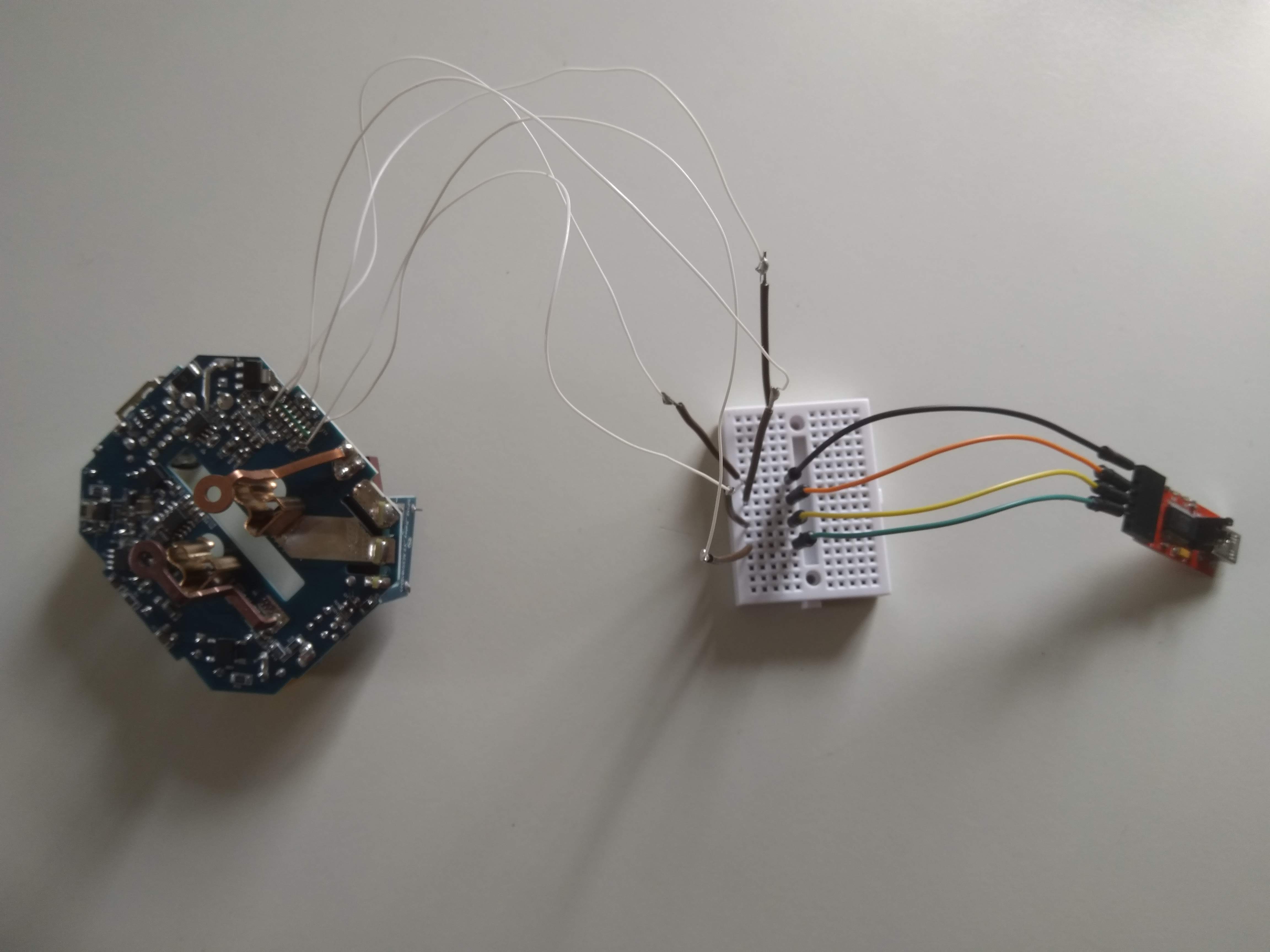
@GoNzCiD DO you have photo which pins and how did you connect flasher ?
zewelor
on 9 May 2019
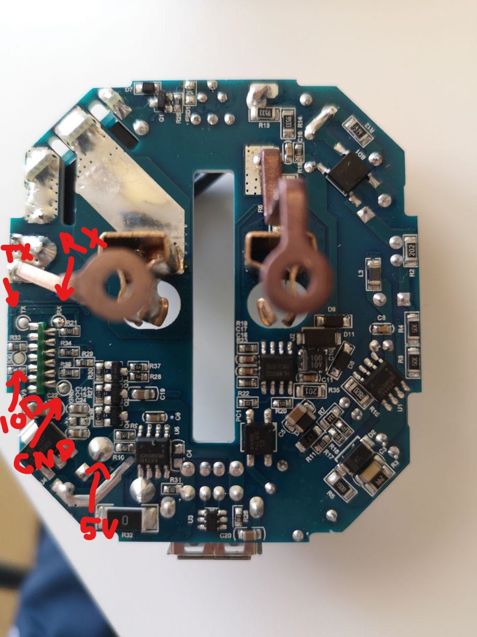
IOD => IO0 short to gnd on boot to enter in flash mode. @zewelor
And flashed with NodeMCU-PyFlasher-4.0
GoNzCiD
on 11 May 2019
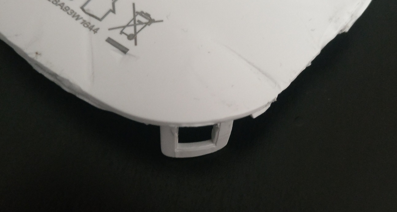
@GoNzCiD Thanks for info. Just to be sure, 5V is correct, not 3.3V ?
zewelor
on 12 May 2019
@GoNzCiD Thanks for info. Just to be sure, 5V is correct, not 3.3V ?
Yes, look at the pcb on the other side:

GoNzCiD
on 13 May 2019
Right thanks !
zewelor
on 13 May 2019
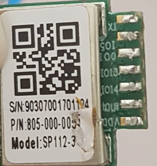
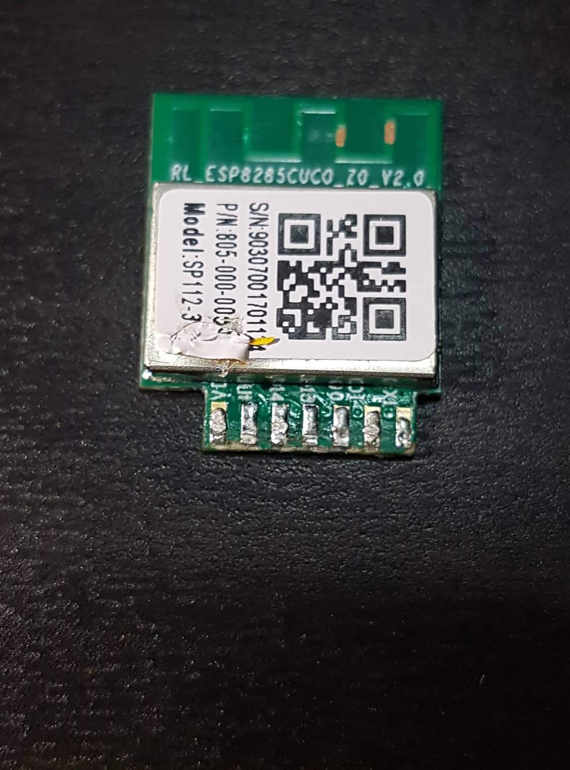
I adding more photos esp8285 from shp5

 waiet
on 14 May 2019
waiet
on 14 May 2019
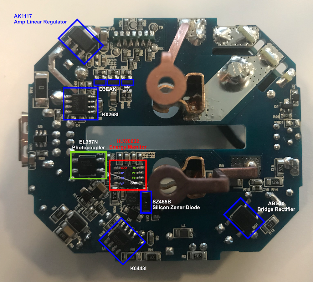
Energy monitoring is done with an HLW8032 (https://datasheet.lcsc.com/szlcsc/Hiliwei-Tech-HLW8032_C128023.pdf)
I guess one of the outputs (probably PF) is sent through an photocoupler (EL357N) to one of the IO pins of the ESP8285.
 thomasklingbeil
on 16 May 2019
thomasklingbeil
on 16 May 2019
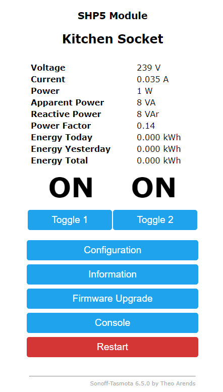
Apart from the power monitoring, the device already seems to work: https://github.com/blakadder/templates/blob/master/_templates/blitzwolf_SHP5
To update my guess from earlier today: It seems as if PF is the only pin of the HLW8032 that is NOT connected. Thus, it seems more likely, that the serial connection is used. It should be UART with 4800bps, Start/Stop Bit and even parity. Every 50ms there should be 24 byte of data.
thomasklingbeil
on 16 May 2019
Just ordered one to write a new nrg driver for serial HLW8032 support.
 arendst
on 17 May 2019
arendst
on 17 May 2019
While comparing the datasheets from HLW8032 (chinees) with CSE7766 (english) the resemblance is striking.
For those owning this device you might want to try the CSE7766 RX/TX config option in Tasmota to check if any energy measuring is shown.
arendst
on 17 May 2019
Apart from the power monitoring, the device already seems to work: https://github.com/blakadder/templates/blob/master/_templates/blitzwolf_SHP5
This module have also control of USB port on GPIO5.
My config is following:
template: '{"NAME":"BlitzWolf SHP5","GPIO":[56,255,57,255,255,22,255,255,255,255,21,255,17],"FLAG":0,"BASE":18}' - button contorling 230 V relay
or
template: '{"NAME":"BlitzWolf SHP5","GPIO":[56,255,57,255,255,22,255,255,255,255,21,255,18],"FLAG":0,"BASE":18}' - button contorling 5 V USB
Energy measuring using CSE7766 RX/TX on GPIO1 and GPIO3 is not working.
 kamkilt
on 20 May 2019
kamkilt
on 20 May 2019
Thx for testing CSE7766. When mine arrives I'll try to implement HLW8032
arendst
on 20 May 2019
Does the regular Serial output of Sonoff Tasmota need to be disabled first?
thomasklingbeil
on 20 May 2019
No, that's been handled by the CSE7766 driver. Did you try to swap RX/TX too?
This works for CSE7766:

arendst
on 20 May 2019
I’ll give it a try soon. Unfortunately it seems that my first SHP5 has stopped working...
Side note: It seems that the ESP and the power monitor IC have different power supplies, so it probably needs to be connected to mains power to fully work.
thomasklingbeil
on 20 May 2019
No, that's been handled by the CSE7766 driver. Did you try to swap RX/TX too?
This works for CSE7766:
It started working, i have changed SerialLog to 0, Baudrate to 4800, but also trying to set CSE7766 on different GPIOs, so I don't know what finally helped, but it works on GPIOs that You send.
On start voltage was about 129 V, i calibrated it to my voltage 240 V.
I will check if it showing right values in the evening.
kamkilt
on 20 May 2019
So my final template is:
{"NAME":"SHP5","GPIO":[56,145,57,146,255,22,0,0,255,255,21,255,18],"FLAG":0,"BASE":18}
kamkilt
on 20 May 2019
Only the shown GPIO's are supported for CSE7766 serial connection so all others will fail.
Glad it works!
arendst
on 20 May 2019
Anyone has been able to flash it ?
I did it many times without issues with BW-SHP6 but with this the RX light of the programmer never turns on. (tried on 2 different SHP5)
Maybe I should use an external power supply? My programmer has 5<->3,3 power switch but doesnt work.
 miquelbotanch
on 2 Jun 2019
miquelbotanch
on 2 Jun 2019
Just did a serial upload as tuya-convert doesn't work anymore due to unsupported https.
Flashing went fine.
Make sure that once you activate the SHP5 template serial comms changes to 4800 bps even parity. That worked for me.
arendst
on 3 Jun 2019
Fancy soldering & wiring 😊
 Jason2866
on 3 Jun 2019
Jason2866
on 3 Jun 2019
I calibrated BW-SHP5 using 60 W bulb, with load energy measure is correct, but without anything connected it always shows about 3 W, it's not an USB output, because is not changing when something is connected to USB output, is there some way to calibrate energy measure to show 0 W when nothing is connected?
I have two modules and both shows same values.

kamkilt
on 3 Jun 2019
Probably not as I suspect the sensor is connected before the SHP5 logic so it will always measure the load of the SHP5.
arendst
on 4 Jun 2019
The final SHP5 template should be this:
{"NAME":"SHP5","GPIO":[57,145,56,146,0,22,0,0,0,0,21,0,18],"FLAG":0,"BASE":18}
where the blue led represents the link info and the red led follows any power setting. As other GPIO's cannot be used they need to be set to 0.
arendst
on 4 Jun 2019
Updated wiki and closing
arendst
on 4 Jun 2019
@kamkilt if you do not want to measure loads below 5W you might want to set define CSE_MAX_INVALID_POWER in file xnrg_02_cse7766.ino from 128 to 1.
This will disable showing invalid power measurments usually below 5W.
arendst
on 4 Jun 2019
Use SetOption39 to control handling of invalid power measurments.
The HLW8032 reports invalid power often if values below 5W are found. During this situation it sometimes reports a valid load. By setting SetOption39 to 128 (default) it must read at least 128 invalid power readings before reporting there is no load.
So to discard all loads below 6W simply set SetOption39 to 1 (0 will reset to default on next restart) so it will report no load below 6W.
arendst
on 4 Jun 2019
Hello
How can I open the case? There is a screw on the bottom. I could solve that.
But how is it going now?
Can someone give me a hint.
Thank you
 chkbln
on 6 Jun 2019
chkbln
on 6 Jun 2019
Hello
How can I open the case? There is a screw on the bottom. I could solve that.
But how is it going now?
Can someone give me a hint.Thank you
There are 1 screw and on the corners are clips. After screwing out the screw I opened case with old club card

waiet
on 7 Jun 2019
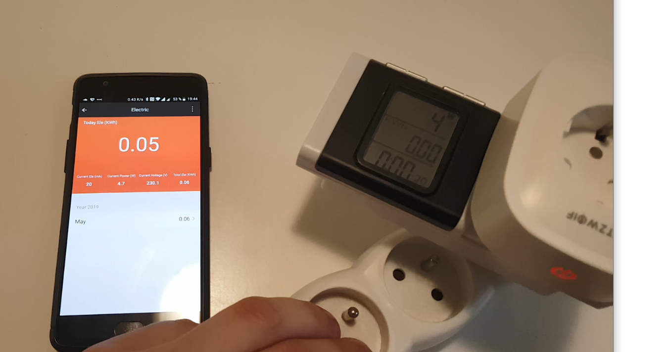
I calibrated BW-SHP5 using 60 W bulb, with load energy measure is correct, but without anything connected it always shows about 3 W, it's not an USB output, because is not changing when something is connected to USB output, is there some way to calibrate energy measure to show 0 W when nothing is connected?
I have two modules and both shows same values.
I measured the energy consumption without a load with original fw. Power consumption still was circa 4w on blitzwolf app and too on power meter after shp5. See image
waiet
on 7 Jun 2019
Does it draw power with the relays off?
 meingraham
on 7 Jun 2019
meingraham
on 7 Jun 2019
On this img relays were power on, but with power off is result the same
waiet
on 7 Jun 2019
Turn on weblog 4 and see if you are getting any checksum errors.
What is Relay2 controlling?
meingraham
on 7 Jun 2019
What is Relay2 controlling?
USB Output.
kamkilt
on 8 Jun 2019
If you do not want to see measurements below 5W use the latest dev release and execute command setoption39 1 as documents earlier in this thread.
arendst
on 8 Jun 2019
If you do not want to see measurements below 5W use the latest dev release and execute command
setoption39 1as documents earlier in this thread.
I did and it's working well. thanks.
kamkilt
on 8 Jun 2019
But shp 5 compared to the shp 6 has relatively high consumption without any load.
That's probably not a software issue. Tasmota is working perfectly.
waiet
on 8 Jun 2019
But shp 5 compared to the shp 6 has relatively high consumption without any load.
That's probably not a software issue. Tasmota is working perfectly.
I measured mine using Sonoff pow R2 and SHP5 gets around ~ 1 - 1.2 W, while SHP6 takes around 0.8 - 1 W, relays on both turned on.
Connecting SHP5 to SHP6, and reading measures from SHP6 gives similar results, so I don't see that high difference in consumption.
kamkilt
on 9 Jun 2019
Dont try to measure such low power consumptions with this devices.
You will get tolerances around 100% or even more. Keep in mind what the cost.
Precises power metering devices for measuring such low consumptions does cost real money...
So every value between 1W and 5w COULD be correct
Jason2866
on 9 Jun 2019
It seems the Gosund SP112 (https://www.amazon.de/dp/B07PMW88L7) is the same as the SHP5, at least the template for the SHP5 works flawlessly for the Gosund as well. So thanks a lot for that!
However I'm also getting strange power readings of the power consumption of the switch itsels. Without any load connected and both relays set to OFF, my power meter says 9 Watts (the same with both relays on). When I measure one SP112 with the other SP112 (after calibration) it says about 1 Watts. Can anyone with a previse power meter measure the SHP5 (or SP112) without any load?
 maschere
on 27 Jun 2019
maschere
on 27 Jun 2019
Hey guys, thanks for this nice discussion so far. I have been trying to flash the SP112 without any success so far. I have the following items:
- Gosund SP112
- esptool (executable) for Mac
- USB adapter CP2102 (/dev/tty.SLAB_USBtoUART)
I think it cannot enter the flash mode. I shortened the IO0 and Gnd, upon plugin in the UART, but I only hear the relay "clicking" but the blue LED is still blinking. The only difference I hear is the relay that clicks once I remove the IO0 and Gnd cable.
Any help is very welcome.
 hemy81
on 4 Aug 2019
hemy81
on 4 Aug 2019
Hi
I connect GPO0 and GND together and then I plug the UART into the USB port.
The LED lights up red. Then I flash.
greeting
chkbln
on 4 Aug 2019
Hmm, that‘s what I did. I connected IO0 with GND and put the UART into USB port. The LED is not blinking red, but blue. I waited even for 10s with both GND and IO0 connected.
hemy81
on 5 Aug 2019
- GOSUND SP112 is broken?
- GPO0 is not at GND potential? Test the connection for correct contact.
I flashed 4 sockets on Tasmota without any problems
chkbln
on 5 Aug 2019
I just received my GOSUND SP112's and managed to open them without breaking any tabs. ;-)
Just one Idea: Has anybody thought about routing the unused GPIOs 4, 12 and 13 to the unused USB-datalines? This would be perfect for adding sensors via 1-wire, GPIO or I2C. 5V power supply included for free...
One Pin of the ESP-module is not clear to me. The pin between Vdd and GPIO14 - is it TOUT (ADC0) or IO15?
And some additions to the circuit itself: U3 (device-marking 2634 A833 - which is the date-code?) is a dual USB protection IC (such as TI TPS2513A or ST USBLC6-4) which protects plugged USB devices - good, but the pins have no other connection.
In the picture in article https://github.com/arendst/Sonoff-Tasmota/issues/5756#issuecomment-492991170
there are two ICs marked K0443I ans K0268I. This might be the production code. The ICs are one On-Bright OB2502TCPB and one OB2005VCPK. Both should be PWM regulators for the separated power-supplies. Unfortunately, i couldn't find the datasheets.
 wvsbsp
on 19 Aug 2019
wvsbsp
on 19 Aug 2019
@wvsbsp
Please, NEVER CONNECT SENSORS TO A POWER MEASUREMENT DEVICE.
YOU CAN BE ELECTROCUTED.
the gnd pin is directly connected to Mains AC.
For sensors please use a nodemcu instead.
Devices with power measurement MUST BE USED AS IT COMES FROM FACTORY.
DO NOT PUT YOURSELF, YOUR FAMILY AND YOUR HOUSE IN DANGER
Please, read the wiki! This warning is everywhere.
 ascillato
on 19 Aug 2019
ascillato
on 19 Aug 2019
Related issues
 Vujagig
·
3Comments
Vujagig
·
3Comments
 JoergZ2
·
3Comments
JoergZ2
·
3Comments
 luisfpinto
·
3Comments
luisfpinto
·
3Comments
 esp32x
·
3Comments
esp32x
·
3Comments
 ximonline
·
3Comments
ximonline
·
3Comments
Most helpful comment
The final SHP5 template should be this:
where the blue led represents the link info and the red led follows any power setting. As other GPIO's cannot be used they need to be set to 0.