Is Shelly 1PM supported?
https://shelly.cloud/shelly-1pm-wifi-smart-relay-home-automation/
Cant find any Info about this
 lechk82
All 41 comments
Not fully. You can use the following template, does not have power monitoring.
{"NAME":"Shelly 1PM","GPIO":[56,0,0,0,82,0,0,0,0,0,0,21,0],"FLAG":2,"BASE":18}
 allistermaguire
on 27 Apr 2019
allistermaguire
on 27 Apr 2019
thanks. unfortunately power monitoring is what i need. Any plans for future implementation?
lechk82
on 27 Apr 2019
@allistermaguire - with the GPIO mapped as you have, have you tried using the Shelly 2 or Shelly 2.5 as the BASE device instead of Generic?
 meingraham
on 27 Apr 2019
meingraham
on 27 Apr 2019
Is the Power Monitoring IC a MCP39F5?
Assigning TX, RX and RST to the appropriate GPIOs should do the trick, right?
lechk82
on 27 Apr 2019
I have tried both Shelly 2 and 2.5 as the base for power monitoring. But apparently, the 1PM is different again from both of those. I asked in the Shelly support channel and energy/power monitoring is via impulse which looks to be on GPIO5, map counter to it.
Voltage is available as well but Dimitar wasn't sure what sensor is used and the team away on Easter break. Someone else said Tasmota support is coming.
allistermaguire
on 28 Apr 2019
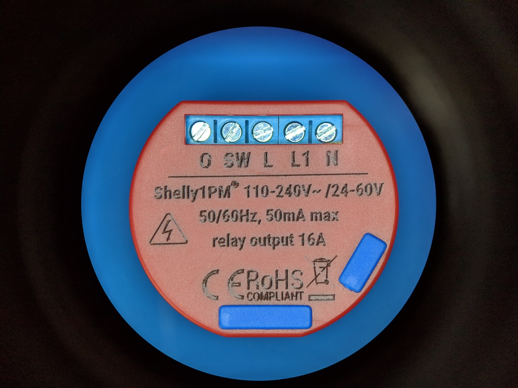
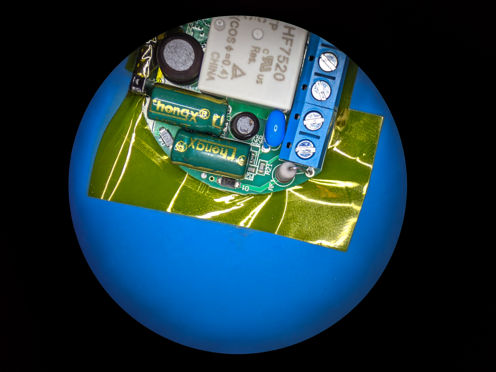
I received my Shelly 1PM and 2.5 order a few weeks ago. Unfortunately I don't have spare time to help here right now. However I can provide some pictures and info of the Shelly 1PM.
It uses the BL0937 / 1852AYH / D798442Z - Shanghai Belling "Single phase, built-in oscillator, active power, RMS, and energy metering" IC.
I had to hold my smartphone in one eyepiece of microscope. I don't have a camera for it yet.


 JeremiahGillis
on 28 Apr 2019
JeremiahGillis
on 28 Apr 2019
Great info.
The BL0937 is supported on blitzwolf devices. You might want to try that as a base. Problem is still to find which three gpios are being used for the BL0937...
 arendst
on 28 Apr 2019
arendst
on 28 Apr 2019
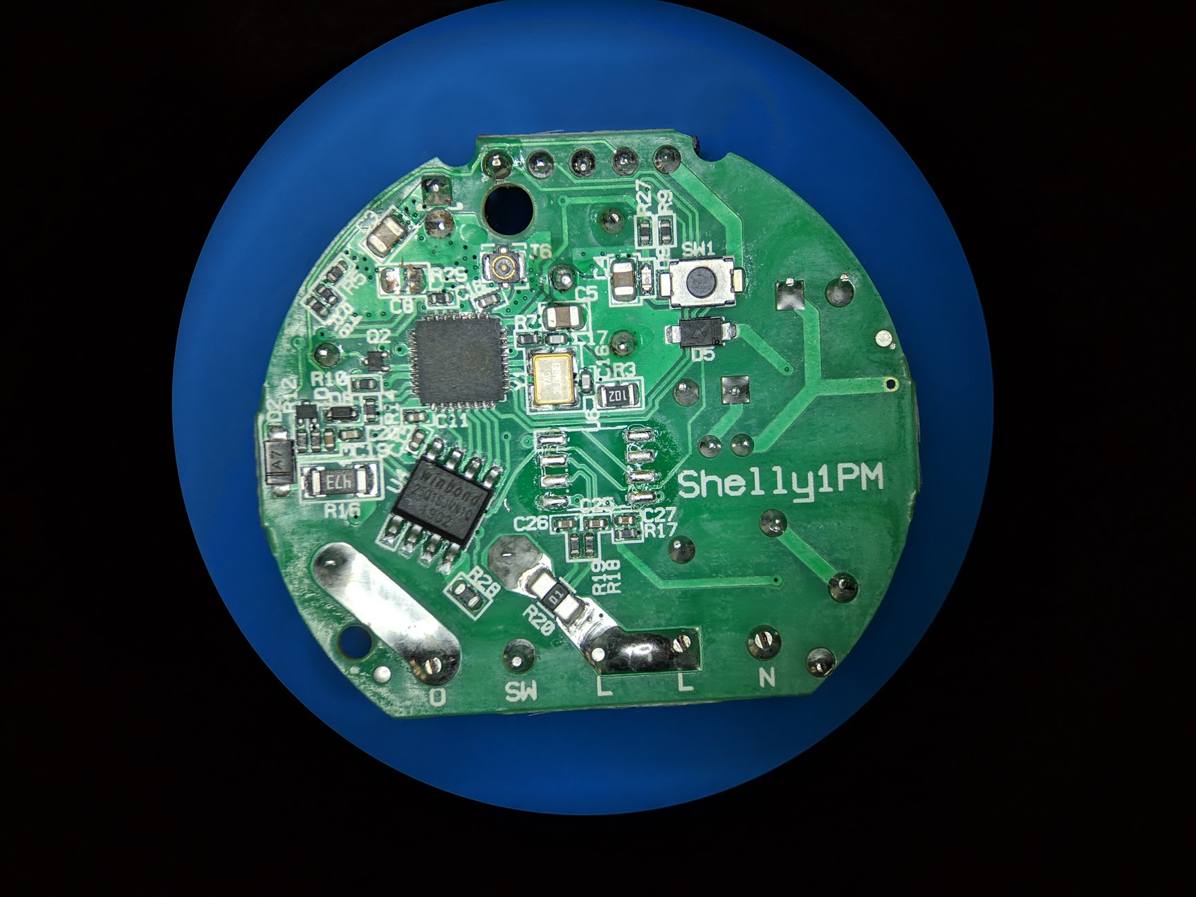
Unfortunately only BL0937 CF PIN 6 is connected to MCU PIN 24. CF1 and SEL on BL0937 are not connected to anything. I did an continuity check and also looked under the BL0937. CF1 and SEL have no vias. This means that Tasmota will only be able to report power usage and overcurrent (36A) with the CF pin. Maybe they had no open pins for CF1 and SEL or no reason to measure voltage and current. Someone is welcome to check in the Shelly APP to see if they only display power consumption.
Maybe SW1 GPIO could be used for CF1. SEL has an internal pulldown so CF1 would represent current. Voltage could then be determined from the power and current. This would require modification with a jumper. Just food for thought.
JeremiahGillis
on 29 Apr 2019
The app only seems to have power usage.
I asked in the Shelly support forum and was told there is power usage (looks to be GPIO05) and voltage.
allistermaguire
on 29 Apr 2019
If there is voltage then cf1 must be connected too.
When i'm back from holiday i'll ask shelly support team.
arendst
on 29 Apr 2019
I already asked on FB, but so far no answer.
 majuss
on 29 Apr 2019
majuss
on 29 Apr 2019
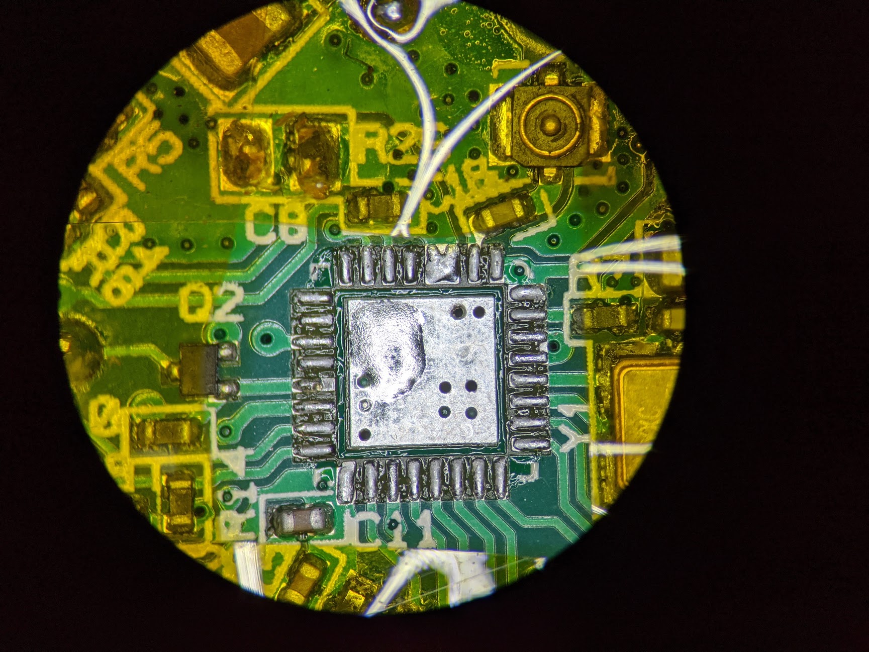
Well I did check continuity to all MCU pins and both CF1 and SEL were open. If they were connected you would see a via next to the pads of PIN 7 and 8 of the BL0937. They are not connected to the MCU.
JeremiahGillis
on 29 Apr 2019
The stock firmware does not seem to indicate voltage. Here is a snapshot of ip/status:
{"wifi_sta":{"connected":true,"ssid":"XXXXXX","ip":"192.168.2.100","rssi":-56},"cloud":{"enabled":false,"connected":false},"mqtt":{"connected":false},"time":"19:48","serial":1,"has_update":false,"mac":"840D8EXXXXXX","relays" :[{"ison":true, "has_timer":false,"overpower":false}],"meters":[{"power":23.29,"is_valid":true,"timestamp":1556567323,"counters":[22.667, 22.693, 22.697],"total":20281}],"temperature":55.09,"overtemperature":false,"update":{"status":"idle","has_update":false,"new_version":"20190423-080637/v1.4.9-switch1pm-hotfix4@f8c51629","old_version":"20190423-080637/v1.4.9-switch1pm-hotfix4@f8c51629"},"ram_total":50960,"ram_free":39688,"fs_size":233681,"fs_free":174947,"uptime":106589}
lechk82
on 29 Apr 2019
Ok. It's only power then.
Does that work as expected with tasmota? (forgetting the non relevant voltage, current and apparent and reactive power for the moment).
arendst
on 29 Apr 2019
I see there istemperature too. If so try to enable the anaog input astemperature sensor like the shelly2.5 and see if it works.
arendst
on 29 Apr 2019
Temperature works, so do the Energy Today, Yesterday and Total.
Power doesn't but that just appears to be a code thing due to energy_voltage and energy_current being 0.
allistermaguire
on 29 Apr 2019
@allistermaguire can you please share your new template?
majuss
on 30 Apr 2019
{"NAME":"Shelly 1PM","GPIO":[56,0,0,0,82,134,0,0,131,132,0,21,0],"FLAG":2,"BASE":18}
131 and 132 do nothing but are needed for energy/power outputs in the UI, Mqtt etc.
Please note that I have made changes to the code for 'Power 15W' to work, that will be 0 for you but the Energy Today, Yesterday, Total will increment.

allistermaguire
on 30 Apr 2019
@allistermaguire,
Are you looking to fork Tasmota and create a PR to have @arendst incorporate the power management modifications mentioned above? The real basis of my question is whether should go ahead and publish his 1PM template in the repository or wait for that.
Regards.
Mike
meingraham
on 30 Apr 2019
I suggest to publish this one with a remark that I will release final support mid may. I will have to make some changes to keep correct hardware detection and alllowing only one gpio.
arendst
on 30 Apr 2019
@allistermaguire
Please create a new template in the repository and include your notes and Theo's comment and timeline. An update to the template page can be once final support is available.
Mike
meingraham
on 30 Apr 2019
I have added a template to the repository as requested.
If others want power reading in the interim before Theo's changes are released then it is a pretty simple code change. Comment lines 588 - 590
sonoff/xdrv_03_energy.ino
// if (apparent_power < energy_active_power) { // Should be impossible
// energy_active_power = apparent_power;
// }
Allister
allistermaguire
on 1 May 2019
Using template
{"NAME":"Shelly 1PM","GPIO":[56,0,0,0,82,134,0,0,0,0,0,21,0],"FLAG":2,"BASE":18}
with latest release 6.5.0.10 should look like

arendst
on 13 May 2019
@arendst I can confirm Shelly 1PM is working (5min so far) correctly with the new code and template.
I have also tested 6.5.0.10 on a Shelly 2.5 and 'Reactive Power' doesn't update and is '0 VAr' on both the WebUI and Console.
allistermaguire
on 14 May 2019
For VAr did you use an inductive load?
arendst
on 14 May 2019
Turns out the first one I tested on doesn't for switch 1. Switch 2 on it does and it reports VAr. My apologies.
allistermaguire
on 14 May 2019
Hi guys! I know this thread is closed. But I'm trying to flash shelly 1pm now and I can't even put it into the flash mode. I do touch GPIO0 to the ground but it doesn't work. Do you know how to do that?
 slavkobrzeg
on 20 Dec 2019
slavkobrzeg
on 20 Dec 2019
Please, address this to the Tasmota Support Chat. The chat is a better and more dynamic channel for helping you. Github issues are meant for Tasmota Software Bug Reporting.
Please check the Contributing Guideline and Policy and the Support Guide.
Thanks.
Support Information
See Wiki for more information.
See FAQ for common questions/answers and links if none of your question is in the list
See Chat for more user experience.
See Community for forum.
See Code of Conduct
 ascillato
on 20 Dec 2019
ascillato
on 20 Dec 2019
Unfortunately only BL0937 CF PIN 6 is connected to MCU PIN 24. CF1 and SEL on BL0937 are not connected to anything. I did an continuity check and also looked under the BL0937. CF1 and SEL have no vias. This means that Tasmota will only be able to report power usage and overcurrent (36A) with the CF pin. Maybe they had no open pins for CF1 and SEL or no reason to measure voltage and current. Someone is welcome to check in the Shelly APP to see if they only display power consumption.
Maybe SW1 GPIO could be used for CF1. SEL has an internal pulldown so CF1 would represent current. Voltage could then be determined from the power and current. This would require modification with a jumper. Just food for thought.
Dear @JeremiahGillis,
Thanks for investigating, very helpfull!
I noticed the "Shelly Plug S" uses the same BL0937 ship, where the CF1 and SEL are actually connected to GPIO14 (Pin 9) and GPIO12 (Pin 10).
From your picture it seems that Pin 9 and 10 are unused in the Shelly 1PM. Could you confirm this?

I'm willing to possibly brick/sacrifice a Shelly 1PM device to try modifing it. Connecting:
- BL0937-Pin8 => ESP8266EX-Pin10
- BL0937-Pin7 => ESP8266EX-Pin9
You think it has any possibility of working? Any pointers/hints on this would be highly appreciated!
Kind regards
 AdminHodor
on 18 Feb 2020
AdminHodor
on 18 Feb 2020
Just remember to keep yourself safe, 230 V is not joke :) Maybe test yor RCCB/RCD before plugging it into high voltage.
majuss
on 18 Feb 2020
@AdminHodor Yes, MCU PIN 9 & 10 are not connected to anything. You can clearly see there are no vias for these pads. I still had this Shelly 1PM apart so I decided to remove the MCU. I should have looked at the MCU datasheet and I would have realized it was just a heatsink area. O well... I can use the practice anyway. I can solder it back on.
Make sure you only work on the PCB when there are no external wires connected to the Shelly 1PM. This will keep you safe and prevent damage to the PCB. Be sure that the Shelly 1PM has been disconnected from your mains for awhile so any capacitors bleed down.
I would wire it just like the "Shelly Plug S" if that is how they do it. I would keep the two jumpers within the red boundary below. Obviously yours will still have the BL0937 on the PCB. I just used my old picture to show the red boundary.

The highest voltage within the red boundary is 3.3V. I would run the wires right over the MCU and the BL0937. Keep the wires as short as possible. Make sure they don't stick way up in the air. Inspect your solder joints and jumper wire insulation so nothing is shorted. I would use something like 30 gauge solid core wiring. These signals will be very low current so you could use smaller or larger wiring.
Once you validate that this actually works, I would put use a dab of gel super glue in the areas show with the orange circles. This will provide some strain relief for the jumper wire solder joints. Don't use the normal super glue as it will run all over everything even if you keep it in the freezer. You might be able to get away without using any glue.
Honestly I have no idea why Shelly didn't connect theses. It seems like an oversite. I was planning on doing this investigation as some point. Sadly I have too many other responsibilities so all of my Shelly devices are just sitting in a box. I should have just designed my own and formed a business way back when I started looking into this market.
Anyway, please let us know if this works. Then I will proceed to modify all my Shelly 1PM devices before I install them.
JeremiahGillis
on 19 Feb 2020
I have bridged the pins in the following configuration:
BL0937-Pin8 => ESP8266EX-Pin9 (GPIO 14)
BL0937-Pin7 => ESP8266EX-Pin12 (GPIO 13)
I've tried this because it was the easiest to solder, but i don't seem to be able to get a readout. If I set GPIO13 as HLWBL CF1 and GPIO14 as HLWBL SELi in Tasmota, all power monitor chip readouts are gone (including power). However, if I set them back to None and leave GPIO5 as BL0937 CF I get the power readout again.
Is BL0937-Pin8 => ESP8266EX-Pin10 & BL0937-Pin7 => ESP8266EX-Pin9 the only possible working configuration or could there be a different reason why it's not working?
 Vorta
on 20 Feb 2020
Vorta
on 20 Feb 2020
These findings are quite interesting thank you for sharing your insight!
While tinkering with mine, I broke of D1 :( could you please upload an image of the other side of the board, so I can get it back on in the right direction? Thank you :)
majuss
on 21 Feb 2020
JeremiahGillis
on 21 Feb 2020
I've soldered
BL0937-Pin8 => ESP8266EX-Pin10
BL0937-Pin7 => ESP8266EX-Pin9
Set GPIO12 to HLWBL SELi and GPIO14 to HLWBL CF1.
However, the readouts are far from ideal. As soon as GPIO12 starts acting as HLWBL SELi, power readout is lost. There is some readout coming in but it's incorrect.
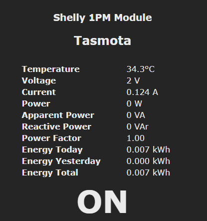
This is what I get with 30W resistive load, when GPIO12 is set as none:

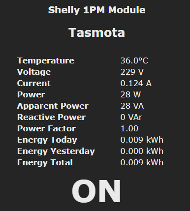
This is what happens when I configure GPIO12 and GPIO14:
The current readout seems to be close to correct for 30W @ 230V.
Edit:
It just started working all of a sudden.
Vorta
on 22 Feb 2020
@Vorta That is good if it actually is working correctly. I just flashed my Shelly 1PM with Tasmota. I will try and add the jumpers tomorrow and validate your findings.
JeremiahGillis
on 22 Feb 2020
@Vorta The new energy calculations works for me with the jumpers in place. I used your exact GPIO settings. I will post pictures of my jumper wiring this weekend.

JeremiahGillis
on 22 Feb 2020
Here is the template
{"NAME":"Shelly 1PM","GPIO":[56,0,0,0,82,134,0,0,131,0,132,21,0],"FLAG":2,"BASE":18}
I ended up using no superglue as the wires were short. Just be careful when putting the PCB back in the case.
Keep in mind the MCU pin pitch is pretty small. This is not an easy solder job unless you have the correct tools.


This seems like an oversite on Shelly's part to not add in this extra energy data.
JeremiahGillis
on 23 Feb 2020
Great stuff @JeremiahGillis . I asked Shelly team about that on their Facebook group and the answer was: We know about it, but the PCB limitations forced us to omit those two measures.
They said that maybe in version 2.0 they will rethink that, but it will require new certification process to happen.
Again thanks for your "proof of concept".
slavkobrzeg
on 23 Feb 2020
How many layers does the PCB have? It looks quity crowded and if they only have 2 layers this makes sense somehow.
majuss
on 23 Feb 2020
The easiest way I found to solder the jumpers to the ESP chip was to superglue them on the ESP chip with some overhang over the pins. When the glue dried i just bent the overhanging wires to correct positions and pressed the soldering iron on them. Very quick and easy.
Vorta
on 23 Feb 2020
Related issues
 j4k3
·
3Comments
j4k3
·
3Comments
 Vujagig
·
3Comments
Vujagig
·
3Comments
 TylerDurden23
·
3Comments
TylerDurden23
·
3Comments
 wirelesssolution
·
3Comments
wirelesssolution
·
3Comments
 esp32x
·
3Comments
esp32x
·
3Comments
Most helpful comment
Just remember to keep yourself safe, 230 V is not joke :) Maybe test yor RCCB/RCD before plugging it into high voltage.