Tasmota: HW-655 Generic Module w/ PZEM - Endless Reboot Loop
- [x] Searched the problem in issues (https://github.com/arendst/Sonoff-Tasmota/issues)
- [x] Searched the problem in the wiki (https://github.com/arendst/Sonoff-Tasmota/wiki/Troubleshooting)
- [x] Searched the problem in the forum (https://groups.google.com/d/forum/sonoffusers)
- [x] Searched the problem in the chat (https://discord.gg/Ks2Kzd4)
Development/Compiler/Upload tools used: Arduino IDE
Hardware used: HW-655 w/ ESP-01 piggyback
If a pre-compiled release or development binary was used, which one? N/A
You have tried latest release or development binaries? No
19:41:33 MQT: stat/power_monitor/STATUS = {"Status":{"Module":18,"FriendlyName":["Power Monitor"],"Topic":"power_monitor","ButtonTopic":"0","Power":0,"PowerOnState":3,"LedState":1,"SaveData":1,"SaveState":1,"SwitchTopic":"0","SwitchMode":[0,0,0,0,0,0,0,0],"ButtonRetain":0,"SwitchRetain":0,"SensorRetain":0,"PowerRetain":0}}
19:41:33 MQT: stat/power_monitor/STATUS1 = {"StatusPRM":{"Baudrate":115200,"GroupTopic":"sonoffs","OtaUrl":"http://thehackbox.org/tasmota/release/sonoff.bin","RestartReason":"Exception","Uptime":"0T00:00:15","StartupUTC":"2018-12-10T00:41:18","Sleep":0,"BootCount":52,"SaveCount":61,"SaveAddress":"F7000"}}
19:41:33 MQT: stat/power_monitor/STATUS2 = {"StatusFWR":{"Version":"6.3.0.14(sonoff)","BuildDateTime":"2018-11-30T13:36:30","Boot":6,"Core":"2_3_0","SDK":"1.5.3(aec24ac9)"}}
19:41:33 MQT: stat/power_monitor/STATUS3 = {"StatusLOG":{"SerialLog":0,"WebLog":2,"SysLog":0,"LogHost":"","LogPort":514,"SSId":["SSID",""],"TelePeriod":300,"SetOption":["00008109","558180C0","00000000"]}}
19:41:33 MQT: stat/power_monitor/STATUS4 = {"StatusMEM":{"ProgramSize":435,"Free":568,"Heap":16,"ProgramFlashSize":1024,"FlashSize":1024,"FlashChipId":"146085","FlashMode":3,"Features":["00000809","0F002790","00000001","0000009E","000000C0"]}}
19:41:33 MQT: stat/power_monitor/STATUS5 = {"StatusNET":{"Hostname":"power_monitor","IPAddress":"192.168.1.xxx","Gateway":"192.168.1.1","Subnetmask":"255.255.255.0","DNSServer":"192.168.1.1","Mac":"<MAC>","Webserver":2,"WifiConfig":4}}
19:41:33 MQT: stat/power_monitor/STATUS6 = {"StatusMQT":{"MqttHost":"mqttHost","MqttPort":1883,"MqttClientMask":"DVES_%06X","MqttClient":"DVES_xxxxxx","MqttUser":"mqttUser","MqttType":1,"MAX_PACKET_SIZE":1000,"KEEPALIVE":15}}
19:41:33 MQT: stat/power_monitor/STATUS7 = {"StatusTIM":{"UTC":"Mon Dec 10 00:41:33 2018","Local":"Sun Dec 09 19:41:33 2018","StartDST":"Sun Mar 11 02:00:00 2018","EndDST":"Sun Nov 04 02:00:00 2018","Timezone":99,"Sunrise":"07:23","Sunset":"17:15"}}
19:41:33 MQT: stat/power_monitor/STATUS9 = {"StatusPTH":{"PowerDelta":80,"PowerLow":0,"PowerHigh":0,"VoltageLow":0,"VoltageHigh":0,"CurrentLow":0,"CurrentHigh":0}}
19:41:33 MQT: stat/power_monitor/STATUS10 = {"StatusSNS":{"Time":"2018-12-09T19:41:33","ENERGY":{"TotalStartTime":"2018-12-06T10:20:28","Total":0.000,"Yesterday":0.000,"Today":0.000,"Period":0,"Power":0,"ApparentPower":0,"ReactivePower":0,"Factor":0.00,"Voltage":121,"Current":0.000}}}
19:41:33 MQT: stat/power_monitor/STATUS11 = {"StatusSTS":{"Time":"2018-12-09T19:41:33","Uptime":"0T00:00:15","Vcc":3.152,"LoopSet":50,"LoadAvg":38,"Wifi":{"AP":1,"SSId":"SSID","BSSId":"<apMAC>","Channel":6,"RSSI":100}}}
I have a relatively recent TASMOTA version flashed on this device - 6.3.0.14. I'm using this same binary on all of my other ESP devices and they are running without any issues. Before I pull everything apart on this circuit and try a more current version or a pre-compiled binary, I'd like to see if there is something obvious causing the exception throwing into an endless reboot loop.
This is about as far as it gets before it reboots:
00:00:00 Project sonoff Power Monitor (Topic power_monitor, Fallback DVES_xxxxxx, GroupTopic sonoffs) Version 6.3.0.14(sonoff)-2_3_0
00:00:00 WIF: Connecting to AP1 SSID in mode 11N as power_monitor...
00:00:05 WIF: Connected
00:00:05 DNS: Initialized
00:00:05 HTP: Web server active on power_monitor.local with IP address 192.168.1.xx
00:00:06 MQT: Attempting connection...
00:00:06 MQT: Connected
00:00:06 MQT: tele/power_monitor/LWT = Online (retained)
00:00:06 MQT: cmnd/power_monitor/POWER =
00:00:06 MQT: tele/power_monitor/INFO1 = {"Module":"Generic","Version":"6.3.0.14(sonoff)","FallbackTopic":"DVES_xxxxxx","GroupTopic":"sonoffs"}
19:41:25 MQT: tele/power_monitor/INFO2 = {"WebServerMode":"Admin","Hostname":"power_monitor","IPAddress":"192.168.1.xxx"}
19:41:25 MQT: tele/power_monitor/INFO3 = {"RestartReason":"Fatal exception:0 flag:2 (EXCEPTION) epc1:0x402245a8 epc2:0x00000000 epc3:0x00000000 excvaddr:0x00000000 depc:0x00000000"}
19:41:33 MQT: tele/power_monitor/STATE = {"Time":"2018-12-09T19:41:33","Uptime":"0T00:00:15","Vcc":3.152,"LoopSet":50,"LoadAvg":19,"Wifi":{"AP":1,"SSId":"SSID","BSSId":"<apMAC>","Channel":6,"RSSI":100}}
19:41:33 MQT: tele/power_monitor/SENSOR = {"Time":"2018-12-09T19:41:33","ENERGY":{"TotalStartTime":"2018-12-06T10:20:28","Total":0.000,"Yesterday":0.000,"Today":0.000,"Period":0,"Power":0,"ApparentPower":0,"ReactivePower":0,"Factor":0.00,"Voltage":121,"Current":0.000}}
Thanks for your help.
Mike
 meingraham
All 13 comments
Hi since it is a custom compile can you provide the map file so that one can see where the exception originates from?
(EXCEPTION) epc1:0x402245a8
Thanks
 andrethomas
on 10 Dec 2018
andrethomas
on 10 Dec 2018
Where do i find the map file? I looked in the output folder and nothing was obvious. I couldn't find an explicit reference to generating a map file in the Arduino options/preferences. I have the binary I used to flash the device. Can I generate the memory map from it?
meingraham
on 10 Dec 2018
Do you have the elf file ?
xtensa-lx106-elf-objdump -t sonoff.elf > sonoff.map
andrethomas
on 10 Dec 2018
I don't have the elf from the original build, but since my sketch and options have not changed, I found an elf file in my temp folders with a timestamp corresponding to my current Arduino session. I just PM'ed it to you on Discord.
meingraham
on 10 Dec 2018
@arendst @ascillato
The exception emanates from
402245a8 g F .irom0.text 00000017 _Z9tms_isr_1v
Any ideas why there would be an exception coming from the timer interrupt service routine?
andrethomas
on 10 Dec 2018
For additional information... I'm setting this up:
https://github.com/arendst/Sonoff-Tasmota/issues/3626#issuecomment-416976400
I didn't find any specific configuration information for the ESP-01 configuration vs. Theo's Sonoff Basic based solution so I copied that but using a Generic Module setup:
meingraham
on 10 Dec 2018
Hi, with core 2.3.0, Tasmota does not support serial communication in other pins different than the TX and RX (in your template TX should be in TX and RX should be in RX) or you can change the core to 2.4.2 that will support your setup using software serial
 ascillato
on 10 Dec 2018
ascillato
on 10 Dec 2018
OK, I had read about hardware serial vs. software serial and 2.4.2 being needed for the latter. I just don't really know which I'm dealing with in my configuration.
This is my first attempt at setting up "external" inputs to TASMOTA... so, of course, I got it wrong ;-) The circuit uses the TX/RX pins on board to connect the PZEM serial interface to the HW-655 serial pins. So I assumed I was setting up hardware serial (and thought 2.3.0 would be OK). I went by what was labeled as Serial In/Out on the configuration dialog. If this is wrong, what should the GPIO configuration be (assuming I can use hardware serial and retain 2.3.0)?
Instead, do I need to re-flash the ESP-01 on the HW-655 with 2.4.2 core? If so, two questions: 1. Which binary from http://thehackbox.org/tasmota/020402/; sonoff-basic (I'm guessing not), sonoff, or sonoff-sensors? 2. Assuming I still set it up as Generic, what is the GPIO configuration, if different from what I did before?
Thanks.
meingraham
on 10 Dec 2018
PZEM support is included in sonoff.bin @ http://thehackbox.org/tasmota/020402/
You should try using pins other than the hardware TX/RX also.
andrethomas
on 10 Dec 2018
@meingraham
Have you managed to solve your issue?
There is a recent issue exactly as yours with all this explanations if you want to dig deeper. https://github.com/arendst/Sonoff-Tasmota/issues/4472
Hope this clarify this limitation of the core 2.3.0 that can use only hardware serial. Tx with tx and rx with rx. Core 2.4.2 can use software serial on any pin besides the hardware serial.
ascillato
on 10 Dec 2018
Closing this issue as duplicated and as has been answered.
Support Information
See Wiki for more information.
See Chat for more user experience.
 ascillato2
on 10 Dec 2018
ascillato2
on 10 Dec 2018
The Rx & Tx lines on the HW-655 pin header are connected to the Tx & Rx pins (i.e., reversed) on the ESP-01, respectively. The HW-655 serial interface pin header is connected to the serial port on the PZEM-004T. So, I think that the it is the hardware serial GPIO pins on the ESP-01 that are in play. Nevertheless, using the 2.4.2 core binary resolved the issue.
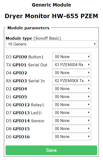
I verified that the Generic Module as originally configured (TX GPIO1 Serial Out: 63 PZEM004 Rx, RX GPIO3 Serial In: 62 PZEM004 Tx) works and registers the corresponding power measurements of the load "attached" to the PZEM.
Thanks for your help.
Mike
meingraham
on 10 Dec 2018
Good stuff, glad you got sorted.
andrethomas
on 10 Dec 2018
Related issues
 jensuffhaus
·
3Comments
jensuffhaus
·
3Comments
 wirelesssolution
·
3Comments
wirelesssolution
·
3Comments
 Joeyhza
·
3Comments
Joeyhza
·
3Comments
 kckepz
·
3Comments
kckepz
·
3Comments
 ximonline
·
3Comments
ximonline
·
3Comments
Most helpful comment
The Rx & Tx lines on the HW-655 pin header are connected to the Tx & Rx pins (i.e., reversed) on the ESP-01, respectively. The HW-655 serial interface pin header is connected to the serial port on the PZEM-004T. So, I think that the it is the hardware serial GPIO pins on the ESP-01 that are in play. Nevertheless, using the 2.4.2 core binary resolved the issue.
I verified that the Generic Module as originally configured (TX GPIO1 Serial Out: 63 PZEM004 Rx, RX GPIO3 Serial In: 62 PZEM004 Tx) works and registers the corresponding power measurements of the load "attached" to the PZEM.
Thanks for your help.
Mike