IMPORTANT NOTICE
If you do not complete the template below it is likely that your issue will not be addressed. When providing information about your issue please be as extensive as possible so that it can be solved by as little as possible responses.
FAILURE TO COMPLETE THE REQUESTED INFORMATION WILL RESULT IN YOUR ISSUE BEING CLOSED
Describe the bug
_A clear and concise description of what the bug is._
6.3.0.5(sonoff) Doesn't know about Sonoff Basic R2.
I bought new Sonoff Basic devices and was surprised to find new hardware inside. The PCB is designated Sonoff RF R2 Power V1.0

It's not clear to me if this is a known device or not. Appologies if you already know about it.
1) Uses esp8285
2) Only 4 pins (power and serial).
3) No GPIO12 - But IO02 avail on a pad.
3) Everything else seems to work OK including button as boot switch.
4) Hardware is better laid out particularly for mains bus.
_Also, make sure these boxes are checked [x] before submitting your issue - Thank you!_
- [x ] _Searched the problem in issues and in the wiki_
- [x ] _Hardware used_ : Sonoff Basic R2
- [x ] _Development/Compiler/Upload tools used_ : Arduino 1.87
- [x ] _If a pre-compiled release or development binary was used, which one?_ : n/a
- [x ] _You have tried latest release or development binaries?_ :
- [ x] _Provide the output of command_
status 0: Not interesting
STATUS 0 OUTPUT HERE - DO NOT DELETE THE MARKERS ABOVE AND BELOW THIS LINE
To Reproduce
_Steps to reproduce the behavior:_
Expected behavior
_A clear and concise description of what you expected to happen._
Screenshots
_If applicable, add screenshots to help explain your problem._
Additional context
I added the following template (in sonoff_template.h) with SONOFF_BASIC_R2 emum. It's cloned from Sonoff Basic. It probably isn't complete but it works for me to use with DS18B20
_Add any other context about the problem here._
{ "Sonoff BasicR2", // Sonoff Basic (ESP8285)
GPIO_KEY1, // GPIO00 Button
GPIO_USER, // GPIO01 Serial RXD and Optional sensor
GPIO_USER, // GPIO02 Optional sensor
GPIO_USER, // GPIO03 Serial TXD and Optional sensor
GPIO_USER, // GPIO04 Optional sensor
0, // GPIO05
0, // GPIO06 (SD_CLK Flash)
0, // GPIO07 (SD_DATA0 Flash QIO/DIO/DOUT)
0, // GPIO08 (SD_DATA1 Flash QIO/DIO/DOUT)
0, // GPIO09 (SD_DATA2 Flash QIO)
0, // GPIO10 (SD_DATA3 Flash QIO)
0, // GPIO11 (SD_CMD Flash)
GPIO_REL1, // GPIO12 Red Led and Relay (0 = Off, 1 = On)
GPIO_LED1_INV, // GPIO13 Green Led (0 = On, 1 = Off)
0, // GPIO14 Optional sensor
0, // GPIO15
0, // GPIO16
0 // ADC0 Analog input
},
(Please, remember to close the issue when the problem has been addressed)
 nottledim
All 43 comments
This is a fake/clone device. There is no ITEAD device with wire bridges.
All orig. ITEAD devices have a sticker on relais
 Jason2866
on 22 Nov 2018
Jason2866
on 22 Nov 2018
That's interesting. It looks identical externally. Maybe that explains the PCB designation too. It seems a bit generic! Serves me right for buying cheap :-)
nottledim
on 22 Nov 2018
That means not that the device has to be bad!
I found wire bridges better than to thin PCB copper layouts for AC
In orig. Basic the put solder on the AC copper lines to get it thicker... Not the best design!
I wouldnt switch more than 3 Ampere with a basic
Jason2866
on 22 Nov 2018
Closing this issue as it has been answered.
Support Information
See Wiki for more information.
See Chat for more user experience.
 ascillato2
on 22 Nov 2018
ascillato2
on 22 Nov 2018
IMO, It has a better design/build than iTead Sonoff Basic.
 wongnam
on 24 Nov 2018
wongnam
on 24 Nov 2018
Sorry for posting in closed topic - but looks like this Sonoff R2 start coming from China and the same on Amazon. Just got completely the same version from China and Amazon. Strange
 timota
on 3 Dec 2018
timota
on 3 Dec 2018
@timota
You are right. It is a real sonoff basic. New PCB layout. Since today supported
Wiki is already changed
Jason2866
on 3 Dec 2018
Do you have link? Can't find it
timota
on 3 Dec 2018
https://github.com/arendst/Sonoff-Tasmota/issues/4515
https://github.com/arendst/Sonoff-Tasmota/wiki/Sonoff-Basic
http://thehackbox.org/tasmota/sonoff.bin
Jason2866
on 3 Dec 2018
ahg sorry. This is Tasmota Wiki.
Anyway many thanks
timota
on 3 Dec 2018
I also got a set of 3 Sonoff Basic with new layout yesterday. And I tried for 6 hours to flash at least one of them but without any success. Tried with Arduino, PlatformIO and esptool.
It seems that the device doesn't enter into programming mode with pressing button while connecting the power.
Did anyone succeeded to flash the new version of sonoff Basic?
 mariantr
on 4 Dec 2018
mariantr
on 4 Dec 2018
On 12/4/18 1:35 PM, Marian Trufasu wrote:
I also got a set of 3 Sonoff Basic with new layout yesterday. And I
tried for 6 hours to flash at least one of them but without any success.
Tried with Arduino, PlatformIO and esptool.
It seems that the device doesn't enter into programming mode with
pressing button while connecting the power.
Did anyone succeeded to flash the new version of sonoff Basic?
Yes, much to my surprise the 2 or 3 I've tried enter boot mode by
pressing the button without issue.
I was expecting trouble because the wiki for Sonoff Dual R2 said there
were difficulties with that.
The programming pin on my units are routed through to set of header pin
pads so it would be possible to put a link in there fairly easily.
There seem to be 2 or 3 different versions of this new product. It was
suggested mine were not original Itead devices. Maybe yours are.
nottledim
on 4 Dec 2018
I've even tried creating a bridge between K_P and Ground, as someone from a german forum suggested.
Tried leaving the bridge for the entire flashing process, didn't worked. I've also soldered two wires on K_P and GND and put them together only on boot, same thing, no success.
One question though, which board should we use? I've seen that this new version uses ESP8285, while the previous one had ESP8266. This means that the board used to flash should be "Generic ESP8285 Module"?
mariantr
on 4 Dec 2018
On 12/4/18 2:30 PM, Marian Trufasu wrote:
> One question though, which board should we use? I've seen
that this new version uses ESP8285, while the previous one had > ESP8266. This means that the board used to flash should be "Generic >
ESP8285 Module"?
Well yes. I think the memory size is different and the pin assignments.
It shouldn't stop esptool from working though.
esptool determines the chip type for itself.
nottledim
on 4 Dec 2018
how do you flash the new model? I can not get it into FLASH MODE
 freemiumdev
on 5 Jan 2019
freemiumdev
on 5 Jan 2019
There is no difference!
Jason2866
on 5 Jan 2019
I can not get it into flash mode. I get these errors:
warning: espcomm_sync failed
error: espcomm_open failed
error: espcomm_upload_mem failed
error: espcomm_upload_mem failed
arduino ide is configured:

freemiumdev
on 5 Jan 2019
Select esp 8266, Before you connect FTDI press and hold button on sonoff
Jason2866
on 5 Jan 2019
Please, for support, address your flashing problem to the Tasmota Support Chat. Thanks
 ascillato
on 5 Jan 2019
ascillato
on 5 Jan 2019
I've even tried creating a bridge between K_P and Ground, as someone from a german forum suggested.
Tried leaving the bridge for the entire flashing process, didn't worked. I've also soldered two wires on K_P and GND and put them together only on boot, same thing, no success.
One question though, which board should we use? I've seen that this new version uses ESP8285, while the previous one had ESP8266. This means that the board used to flash should be "Generic ESP8285 Module"?
i've the same problem. did you solve the problem? if yes, how?
freemiumdev
on 9 Jan 2019
Same problem here can get it into flash mode.
 mikekuzak
on 13 Jan 2019
mikekuzak
on 13 Jan 2019
I've got mine today. I was able to flash it without any problem using Arduino IDE, selecting generic esp8285. My FTDI supplied the required power, nothing connected to the Sonoff normal input/output wires. I've depressed the button, then applied the 3.3v and waited 2 seconds before releasing the button.
 turgu1
on 25 Jan 2019
turgu1
on 25 Jan 2019
It looks like the R2 version has a fuse on the input. Can anyone confirm that?
 preisedj
on 28 Jan 2019
preisedj
on 28 Jan 2019
Yes
Jason2866
on 28 Jan 2019
Guys, I have great news.
I went through lots of different forums and guides and couldn't find any solution so I start digging on my own.
I have the latest version of sonoff with esp8285 and there is no proper guide on the internet how to flash it properly.
I connected standard esp8266(not sonoff), setup serial monitor to 74880 and checked that boot mode for flashing over there is:
rst cause:2, boot mode:(1,0)
and only in that mode I am able to flash Esp8266
So I connected sonoff with serial monitor on 74880 and went to flashing mode(pushing button with power), it turns that at the first time it's
rst cause:2, boot mode:(1,7)
and I am not able to flash with that mode, but there is a solution for that!
After you went to boot mode:(1,7) using gpi0 button and powering up, keep gpi0 button and push power button second time after 1-2 seconds(with serial monitor you can see that it went to expected boot mode:(1,0)) keep that button pushed, start uploading process, and you should be able to flash it now!
 dawidkoldras
on 30 Jan 2019
dawidkoldras
on 30 Jan 2019
I'm new to sonoff and I've been struggling with this board too.
This is what worked for me:
Connect your ftdi or arduino rx to sonoff rx and tx to tx. All the guides say rx->tx and tx->rx which makes senese.
I think they labeled it wrong.
 ab-85
on 5 Feb 2019
ab-85
on 5 Feb 2019
I have just flashed my first 2 Sonoff Basic version 2 devices using the same procedure as for the older versions and using Arduino IDE... had no issues.
I treated them always as if they were ESP8266 and I connected the cables Tx>Rx and Rx>Tx
Absolutely no problems... worked like a charm.
 cbugeja
on 5 Feb 2019
cbugeja
on 5 Feb 2019
The soldering did not work for me at all. But when I just ook 4 male pins, and attached the UART adapter pins to it, and attached the 4 pins (still attached together) in the sonoff, with a little bit of pressure agains it (a pen for example), it worked brilliantly.
Attach wires, then press button, insert usb into pc, release button after 3 seconds. 5v light goes out on usb adapter. Start flashing with ESP EASY FLASHER, select esp8266_1024.bin
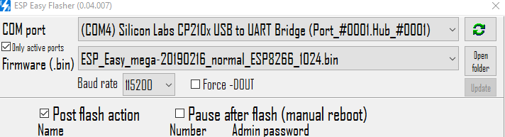
all the lights will start to blink, if it does not, you should press the male pins better, maybe use some tape etc.
PS: also make sure you installed a driver for your UART usb stick! check in device manager that no warningn sign is present, and it should showup in your com port overview.
 QHose
on 23 Feb 2019
QHose
on 23 Feb 2019
QHose's exact instructions worked brilliantly for me too, thanks a lot.
I flashed a Sonoff Basic R2 version 1.0 with http://thehackbox.org/tasmota/sonoff.bin.
I then connected it OK to OpenHAB using the instructions at https://github.com/arendst/Sonoff-Tasmota/wiki.
 NitramGB
on 12 Mar 2019
NitramGB
on 12 Mar 2019
@mariantr I tried everrthing that you tried...Did you find the solution?
 daueee
on 16 Mar 2019
daueee
on 16 Mar 2019
Another point. My ESP 01 was working on 5V i thing that is a problem, but I've used the same adapter before and it works well.
daueee
on 16 Mar 2019
I flashed mine sonoff basic r2 with 3.3V not 5V. tx-rx , rx-tx. Press black button on sonoff and then connect the usb adapter to your pc's usb, after that release the black button.
 mafyata
on 3 May 2019
mafyata
on 3 May 2019
With all the hints above I still wasn't able to flash my Sonoff ESP8285 device. I connected a serial console and the output was all the time:
_ets Jan 8 2013,rst cause:1, boot mode:(3,7)_
_load 0x4010f000, len 1384, room 16_
_tail 8_
_chksum 0xef_
_csum 0xef_
_csum err_
_ets_main.c_
Searching for "espeasy csum err" lead me here: https://www.letscontrolit.com/forum/viewtopic.php?t=3071
In the end the solution that worked for me is to set flash mode setting to DOUT.
 maschue
on 27 May 2019
maschue
on 27 May 2019
DOUT is spelled out in every Tasmota flashing article. In other words, Tasmota flashing 101!
Here are a couple of main pages, but DOUT is mentioned in 18 wiki articles in all.
https://github.com/arendst/Sonoff-Tasmota/wiki/Flashing
https://github.com/arendst/Sonoff-Tasmota/wiki/Theo's-Tasmota-Tips
 meingraham
on 27 May 2019
meingraham
on 27 May 2019
Recently my Sonoff Basic R1 died so bought a new one which turns out to be a R2.
Previously I attached a external switch to GPIO14 but that's not available anymore.
If I understand it correctly i can use IO2 or GPIO13 underneath the led? I think the closed one to the switch on the board if I study R1 pin layout here: https://github.com/arendst/Sonoff-Tasmota/wiki/GPIO-Locations
Both of these pins will make your lights blink when powering on so it doesn't make any difference which pin you use or is it? Which pin is preferred for an external switch, has less issues?
Also on R1 I needed to add a pull up resistor, is that still needed with R2?
And what is meant with the no pullup comment in the wiki for IO2?
https://github.com/arendst/Sonoff-Tasmota/wiki/Sonoff-Basic
Is there a guide somewhere that explains (and shows) how to modify a R2 to use an external switch with it ?
Sorry for mu dumb questions for some but English isn’t my native language and some technical terms don’t make sense to me.
 schumi2004
on 28 May 2019
schumi2004
on 28 May 2019
IO2 has a function on ESP boot mode, so is best to leave it alone.
The chip has internals pull-ups, but on noise environments is better to add
a stronger one.
You can use the RX as GPIO3, Only assure the switch do not interfere when
flashing.
El mar., 28 may. 2019 a las 9:39, schumi2004 (notifications@github.com)
escribió:
Recently my Sonoff Basic R1 died so bought a new one which turns out to be
a R2.
Previously I attached a external switch to GPIO14 but that's not available
anymore.If I understand it correctly i can use IO2 or GPIO13 underneath the led? I
think the closed one to the switch on the board if I study R1 pin layout
here: https://github.com/arendst/Sonoff-Tasmota/wiki/GPIO-Locations
Both of these pins will make your lights blink when powering on so it
doesn't make any difference which pin you use or is it? Which pin is
preferred for an external switch, has less issues?Also on R1 I needed to add a pull up resistor, is that still needed with
R2?
And what is meant with the no pullup comment in the wiki for IO2?
https://github.com/arendst/Sonoff-Tasmota/wiki/Sonoff-Basic
Is there a guide somewhere that explains (and shows) how to modify a R2 to
use an external switch with it ?
Sorry for mu dumb questions for some but English isn’t my native language
and some technical terms don’t make sense to me.—
You are receiving this because you are subscribed to this thread.
Reply to this email directly, view it on GitHub
https://github.com/arendst/Sonoff-Tasmota/issues/4413?email_source=notifications&email_token=ACXBW4K7GWJXAPAORSDGLMTPXURYXA5CNFSM4GF6Z2LKYY3PNVWWK3TUL52HS4DFVREXG43VMVBW63LNMVXHJKTDN5WW2ZLOORPWSZGODWL7SZY#issuecomment-496499047,
or mute the thread
https://github.com/notifications/unsubscribe-auth/ACXBW4IWJ2URYLZCF7IHSZDPXURYXANCNFSM4GF6Z2LA
.
 lalo-uy
on 28 May 2019
lalo-uy
on 28 May 2019
@lalo-uy
Thanks for your reply, i will try GPIO3.
Do you think i also need a capacitor between GPIO3 and GND?
schumi2004
on 28 May 2019
Since i will be using GPIO3 i needed to flash a specific template as mentioned here:
https://github.com/arendst/Sonoff-Tasmota/wiki/Sonoff-Basic
The link that should point to it just reloads Sonoff-Basic wiki page.
And are there instructions for the pull-up resistor and capacitor, didn't found it in the wiki.
schumi2004
on 29 May 2019
No. Flash sonoff.bin. But rather than use Module 1, use this template and then configure GPIO3
P.S. Schumacher 2004 :+1:
meingraham
on 29 May 2019
Guys, I have great news.
I went through lots of different forums and guides and couldn't find any solution so I start digging on my own.
I have the latest version of sonoff with esp8285 and there is no proper guide on the internet how to flash it properly.
I connected standard esp8266(not sonoff), setup serial monitor to 74880 and checked that boot mode for flashing over there is:
rst cause:2, boot mode:(1,0)
and only in that mode I am able to flash Esp8266So I connected sonoff with serial monitor on 74880 and went to flashing mode(pushing button with power), it turns that at the first time it's
rst cause:2, boot mode:(1,7)
and I am not able to flash with that mode, but there is a solution for that!
After you went to boot mode:(1,7) using gpi0 button and powering up, keep gpi0 button and push power button second time after 1-2 seconds(with serial monitor you can see that it went to expected boot mode:(1,0)) keep that button pushed, start uploading process, and you should be able to flash it now!
Hi,
What power button?
Can you please post more details?
Thanks.
 sile70000
on 16 Nov 2019
sile70000
on 16 Nov 2019
Hi,
What power button?
Can you please post more details?
Thanks.
Sonoff Basic R2 v1.0
- K_P to ground
- push the sonoff physical button
- connect TTL USB converter
- wait 2-3 sec. (no LED light)
- release both (K_P and button)
- progress with normal flash.
 createeve
on 27 Nov 2019
createeve
on 27 Nov 2019
I just soldered a wire rapping wire to pin 9 to gain access to GPIO14.
 cityviking
on 26 Feb 2020
cityviking
on 26 Feb 2020
I have just flashed my first 2 Sonoff Basic version 2 devices using the same procedure as for the older versions and using Arduino IDE... had no issues.
I treated them always as if they were ESP8266 and I connected the cables Tx>Rx and Rx>TxAbsolutely no problems... worked like a charm.
This worked for me too. I was scratching my head for a good hour until I saw your comment. RX -> RX and TX -> TX works for me. I'm using a CP2102 USB. Thanks!!
 iqbalibrahim1992
on 9 Apr 2020
iqbalibrahim1992
on 9 Apr 2020
Related issues
 luisfpinto
·
3Comments
luisfpinto
·
3Comments
 j4k3
·
3Comments
j4k3
·
3Comments
 esp32x
·
3Comments
esp32x
·
3Comments
 grizewald
·
3Comments
grizewald
·
3Comments
 belidzs
·
3Comments
belidzs
·
3Comments
Most helpful comment
Guys, I have great news.
I went through lots of different forums and guides and couldn't find any solution so I start digging on my own.
I have the latest version of sonoff with esp8285 and there is no proper guide on the internet how to flash it properly.
I connected standard esp8266(not sonoff), setup serial monitor to 74880 and checked that boot mode for flashing over there is:
rst cause:2, boot mode:(1,0)
and only in that mode I am able to flash Esp8266
So I connected sonoff with serial monitor on 74880 and went to flashing mode(pushing button with power), it turns that at the first time it's
rst cause:2, boot mode:(1,7)
and I am not able to flash with that mode, but there is a solution for that!
After you went to boot mode:(1,7) using gpi0 button and powering up, keep gpi0 button and push power button second time after 1-2 seconds(with serial monitor you can see that it went to expected boot mode:(1,0)) keep that button pushed, start uploading process, and you should be able to flash it now!