Tasmota: Support of WS2812 LEDs in Arilux Case?
Hey all,
I became a big fan of the MagicHome/Arilux LED controllers. Now I am thinking about the next step: WS2812 LED strips for fancy color animations. As I don't want to mess around with drafting PCBs, soldering, creating own cases for Wemos boards etc. I thought about simply using an Arilux AL-LC01 case, power it with 5V, and set one of the pins in Tasmota to WS2812.
Do you see any problems with that idea or should it work as expected?
 gitolicious
All 16 comments
Should works
 ascillato2
on 11 Sep 2018
ascillato2
on 11 Sep 2018
I think I would also need to set one of the pins to ground permanently. (One is hardwired to 5V, one will be WS2812 data pin)
What would I set for this? Is 00 None always ground?
gitolicious
on 12 Sep 2018
I think I would also need to set one of the pins to ground permanently
from the esp8266 ? why?
What would I set for this? Is 00 None always ground?
I don't understand what you want to do with that. for the WS2812 you need from your power source 5V and GND pins. And from your ESP8266 you need the GND pin to GND of your power source and a GPIO to the DATA of the WS2812. The GND needs to be the GND of the ESP8266 and the same GND of the WS2812.
Also remember not to mix 5V with the VCC of the ESP8266 (it is 3.3V)
ascillato2
on 12 Sep 2018
I took some pictures to make it more clearly.
Here you see that the first pin is directly wired to VCC (5-28V). The other pins are to PWM control the LEDs. In the original product that would be an RGBW strip.

If I get it right, all PWM pins are brought up from ESP8266's 3.3V output to VCC by transistors as can be seen on the rear side of the PCB.

So now I want to use the first pin for VCC, the second one would be WS2812 data, the third one would need to be set to GND permanently (this is what my question was about). The other two would not be used.
If I can't use a GND that is set via the ESP8266 I would need to unsolder the transistor and add a jumpwire from the power source input GND to the outgoing pin to my WS2812. Would prefer to solve this via software though.
gitolicious
on 12 Sep 2018
if you use a gpio as gnd, all the current coming from your ws2812 will go trough your esp8266 burning it.
 ascillato
on 12 Sep 2018
ascillato
on 12 Sep 2018
But why didn't that happen when I connected my RGBW strip? Isn't the GPIO connected to the base of the transistor, thus not all current is flowing through the chip?
gitolicious
on 13 Sep 2018
So I gave those parts on the right a closer look. The label says AOLA LT. My guess after looking at this cheat sheet is that LA stands for BF550 PNP transistors. If that's the case, it should be safe to send GND from the GPIO to the base of the transistor.
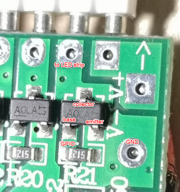
Would that make sense?
gitolicious
on 8 Oct 2018
Should work.
Anyway, I should patch directly gnd from the power source to your gnd of your ws2812.
ascillato
on 8 Oct 2018
Ok, so from an electrical point of view it looks ok.
Problem is the data pin though. I am switching ground with the Tasmota WS2812 GPIO, so for the LED strip data pin, GND and VCC are inverted, right? I guess I would need a pin mode WS2812i? Need to put some more thoughts into this...
gitolicious
on 8 Oct 2018
I shouldn't use the transistors for the ws2812. Better should be that the data pin goes directly from your esp8266 gpio. Just a wire soldered. And also vcc(5v) to vcc of your ws2812. A wire directly. And also gnd.
ascillato
on 9 Oct 2018
That's understood, though it is missing the whole idea of reusing the existing module and case without the need of any modifications on the hardware side. If that's not possible, I see no reason to stick to the Arilux module.
gitolicious
on 9 Oct 2018
Hey guys, here is my final verdict. In the end I didn't succeed in handling it all on the software side, but at least I didn't have to pull long wires across the whole board to fulfill my goal.
After having successfully inverted the WS2812 GPIO inside the NeoPixel library (with some help at https://github.com/Makuna/NeoPixelBus/issues/174) I figured out that this didn't actually solve my problem. The data line was triggered at the correct time through the transistor, but only to GND which doesn't give any effect to the LEDs. _So this was a dead end._
Then I thought about the minimal invasive solution and came up with this:
I removed the first transistor and connected the GPIO side of it (previously: base) to the Arilux output (previously: collector). Now the GPIO is directly connected to the LED's data line.
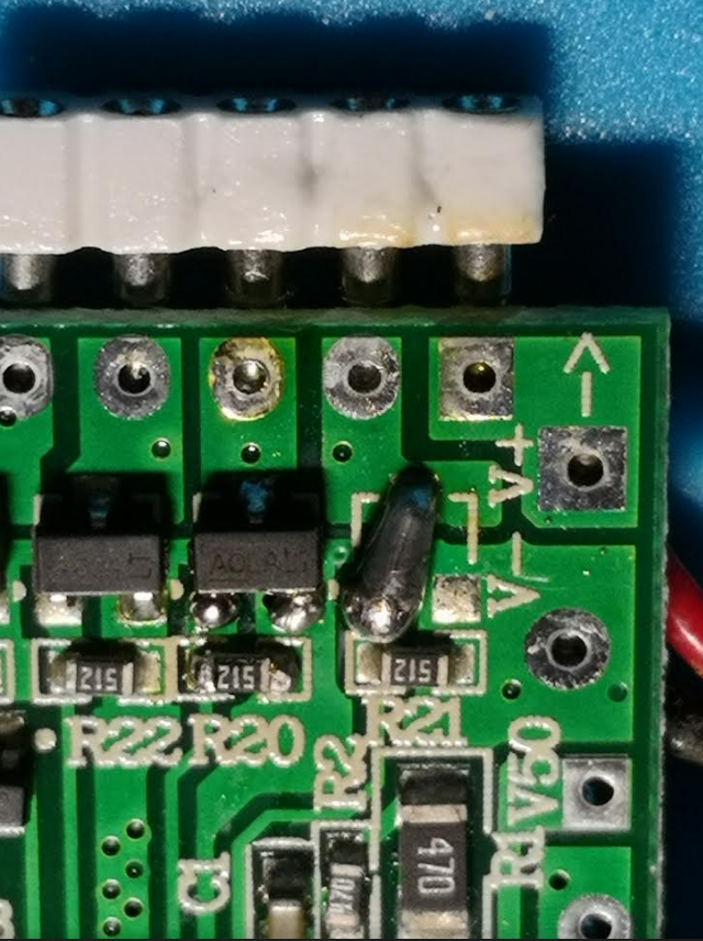
Then I configured Tasmota to a generic module and set D1 GPIO5 (=3rd pin from the right) to Relay1. So still abusing the second transistor to give permanent GND this has to be permanently ON. _Here a solution of my initial request of an "always GND" GPIO configuration would make things easier._
D6 GPIO12 (=2nd pin from the right) is set to WS2812 and is providing the data pin.
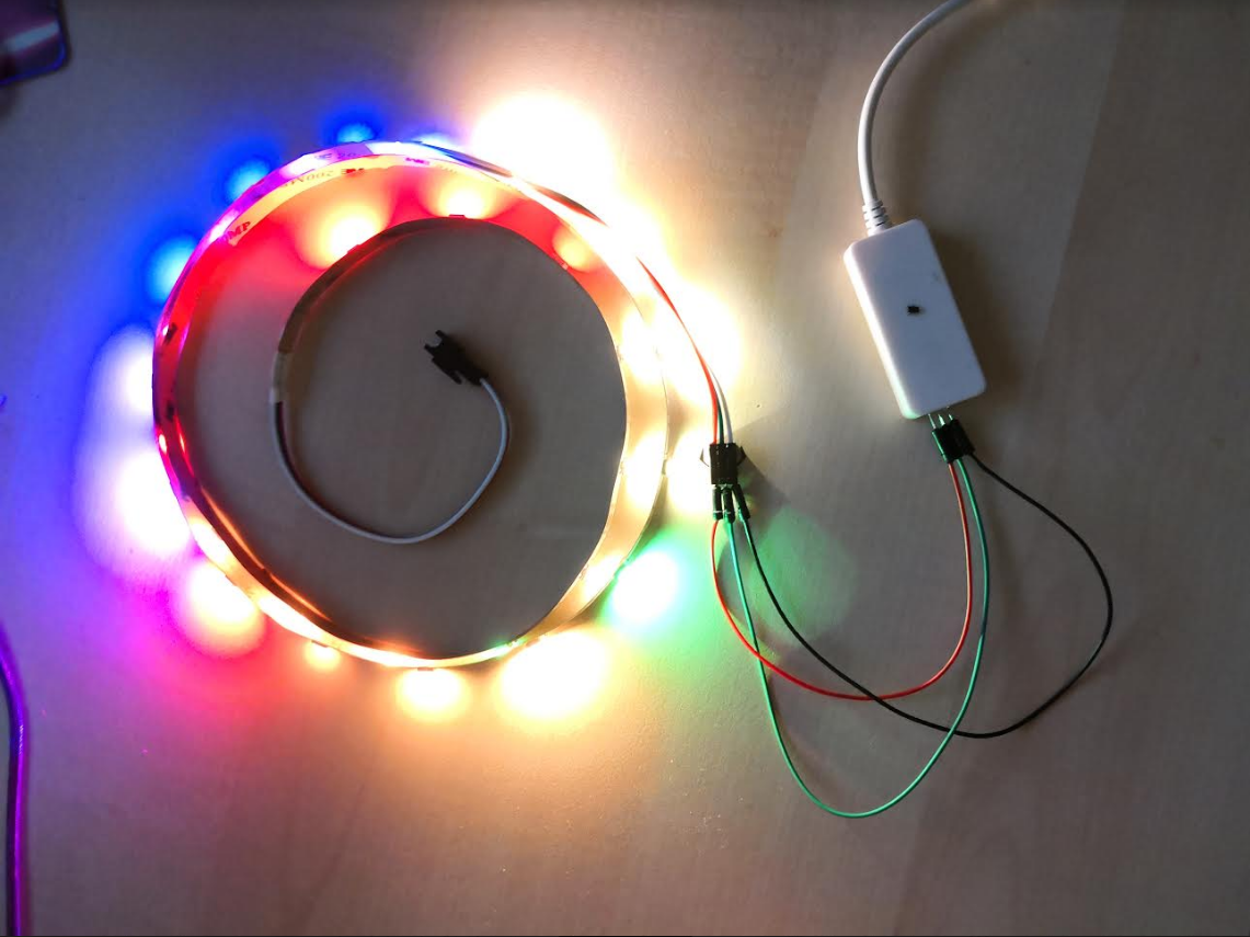
As you can see, when putting it all together the Arilux case gives it a nice and clean look.
Will need to see about stability as I only have it running for a few minutes now, but I am happy with the result for now.
gitolicious
on 11 Oct 2018
Did this continue to work? I am thinking I might try this myself.
 mstrchris83
on 31 Jan 2019
mstrchris83
on 31 Jan 2019
Actually after more fiddling around I didn't get this working reliably. I got some weird colors many times. Investigating with a logic analyzer, all looked promising, but in the analog world things are different. Apparently there is something in the PCB slowing down the rise/fall of the edges so that my WS2812s are reading wrong values. Probably it's just at its limit and maybe a different version/manufacturer of WWS2812s would be working just fine... For me I am currently looking for a different solution.
gitolicious
on 19 Feb 2019
Ahh ok, thanks for the update!
mstrchris83
on 20 Feb 2019
@gitolicious Did you end up finding an alternative solution?
I came across this controller that I'm tempted to try and see if I can get Tasmota running on it:
https://www.amazon.com/Programmable-Controller-Compatible-Assistant-Android/dp/B07DWVQX6N
 rdlaner
on 29 Dec 2019
rdlaner
on 29 Dec 2019
Related issues
 ximonline
·
3Comments
ximonline
·
3Comments
 jensuffhaus
·
3Comments
jensuffhaus
·
3Comments
 grizewald
·
3Comments
grizewald
·
3Comments
 TylerDurden23
·
3Comments
TylerDurden23
·
3Comments
 JoergZ2
·
3Comments
JoergZ2
·
3Comments