Tasmota: Sonoff Basic losing I2C connection (BMP280) after a while
Hi!
I am using a BMP280 connected by I2C with this wiring:
BME280-3.3V -> Sonoff-3.3V
BME280-GND -> Sonoff-GND
BME280-SCL -> Sonoff-TX
BME280-SDA -> Sonoff-RX
Module configuration:
GPIO1 Serial Out -> 05 I2C SCL
GPIO3 Serial In -> 06 I2C SDA
After powering the Sonoff it is showing me good sensor readings, but with an error:
17:28:36 SHT: Sensor did not ACK command
17:28:37 MQT: tele/sonoff-kulicht/SENSOR = {"Time":"2018-08-08T17:28:37","BMP280":{"Temperature":29.3,"Pressure":1007.8},"TempUnit":"C"}
After a while, however, it delivers temperatures like -138°C:
17:38:41 MQT: tele/sonoff-kulicht/SENSOR = {"Time":"2018-08-08T17:38:41","BMP280":{"Temperature":-134.6,"Pressure":1072.0},"TempUnit":"C"}
Then, i2cscan in the console makes it say:
17:59:29 MQT: stat/sonoff-kulicht/RESULT = {"I2CScan":"No devices found"}
Tried Sonoff-Tasmota 5.14.0 and 6.1.1 as well. A different module (BME280) results in the same.
Any ideas?
Marvin

 bearli97
All 18 comments
Is "Serial Log" disabled in Log-Setings?
 Einstein67
on 8 Aug 2018
Einstein67
on 8 Aug 2018
I don't have any basic devices, but I have a few TH16 and other esp8266 based ones. I have several BME280, HTU21 and SHT15. I also tried a BMP280. They all work fine. Do you have a pull-up (or does the sensor have one). I2C requires a pull-up. Some sensors include one, but some don't. I also use GPIO 4 and 14 to avoid the conflict with TX and RX.
 Frogmore42
on 8 Aug 2018
Frogmore42
on 8 Aug 2018
Thank you guys. Serial Logging is/was disabled, I checked this by seriallog, too.
It is this sensor module on the picture and the item description contains the resistor: "The board has selectable I2C address jumper (solder link GS2), I2C pull-up resistors (...)".

I changed SDA/SCL in the settings (still on TX/RX ) and the wires, of course same problem. Next would be to solder GPIO4 and try again.
Btw: What do they mean by "solder link GS2" for changing the I2C address? Where is this GS2?
bearli97
on 9 Aug 2018
The BME280 I2C address will be 0x76 if the SDO pin is grounded or 0x77 if the SDO pin is pulled high. Most likely if not connected it will float so the I2C address may change during usage - Connect SD0 to ground and do i2cscan command, also try to connect to 3.3V and do i2cscan command. If left floating it will change and cause the sensor to appear not responding for Tasmota firmware.
 andrethomas
on 9 Aug 2018
andrethomas
on 9 Aug 2018
@bearli97 Did you test successfully?
andrethomas
on 10 Aug 2018
@andrethomas I soldered SDO to VCC and the adress was 0x77 like you said. It then did work for almost 24 hours, then back to "No devices found". Now I am trying 0x76 with the same module, if the problem persists I'll try another module.
Thank you so far for your help.
Edit: It's losing the connection to 0x76 after a few minutes.
bearli97
on 17 Aug 2018
Possibly a faulty chip I guess - I'm not clear on what the CSB pin is for.
Usually, the only reasons these chips fail is because they revert to SPI mode, but having tied the SDO to GND or VCC would have forced it to stay in I2C mode.
andrethomas
on 17 Aug 2018
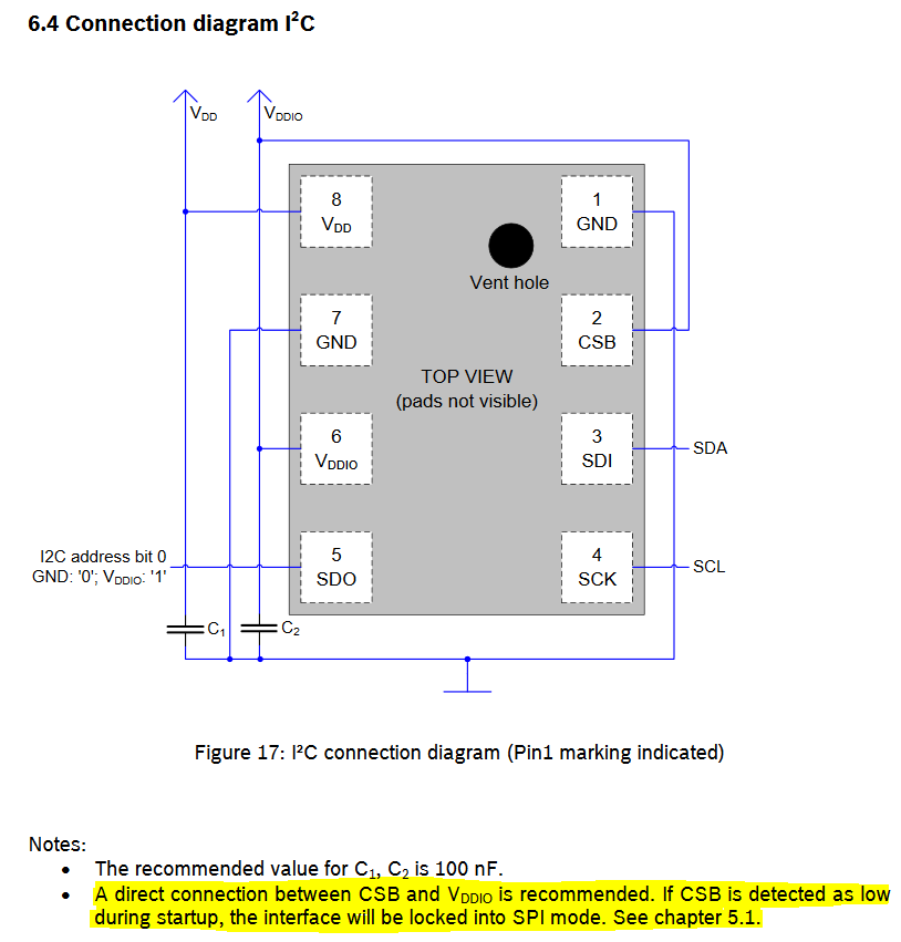
Ok, from datasheet
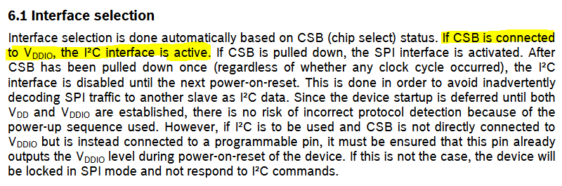
Connect CSB pin to VCC/3.3V also !
andrethomas
on 17 Aug 2018
So something new learnt
CSB->GND = SPI mode, CSB->VCC = I2C mode
SDO = I2C address selection only
andrethomas
on 17 Aug 2018
Sometimes in life, all it needs is somebody who can read. It's running smooth since. None of the help articles I found so far did describe the necessity of this setting. Thank you @andrethomas
bearli97
on 18 Aug 2018
The one I have has the proper pull-UPs and pull-DOWNs.
https://www.amazon.com/HiLetgo-Precision-BMP280-3-3-Atmospheric-Pressure/dp/B01ICN5QPU
Take a look at the schematic, last picture.
The picture you provided is the same. I suspect that you have an intermittent connection/poor solder joint from poor quality control of the reflow or solder paste operations during manufacturing.
Connecting pins (other than power) directly to VCC is generally considered a bad idea by Electrical Engineers, use a pull-up instead.
Frogmore42
on 18 Aug 2018
@Frogmore42 I'd agree with you if it was an IO pin that needed to be externally biased for dual operation and you wanted to bias it high or low by default, but in this particular case it needs to stay to 3V3 or VDDio
Both are high impedance already so no need to use resistors... in fact, the resistor on CSB may actually cause malfunction if value too high.
andrethomas
on 18 Aug 2018
I think the board manufacturer tried to bias it toward I2C but still make it possible for you to use it in SPI mode, hence their pull-up resistor - but this is actually a design fault of the manufacturer in my opinion because if you did want to use it in SPI mode you'd have current leak through the 10k resistor which makes it less efficient. For I2C I would tie it to VCC (VDDIO is the VCC in our case anyway) - If I used this board in SPI mode I would tie it to GND and remove R1 from the PCB as it should not be there.

Same with R4 - only there to allow SPI compatibility - If used for I2C I would remove that resistor also.
andrethomas
on 18 Aug 2018
@bearli97 If you believe your issue is resolved, please remember to close this issue. Thanks
andrethomas
on 18 Aug 2018
Both are high impedance already so no need to use resistors... in fact, the resistor on CSB may actually cause malfunction if value too high.
Many thanks for pointing this out!
Connecting CSB to VDD seems to solve the issue to me too.
BUT: In addition to it and to the two 100nF capacitors C1/C2 on board, I've added a bigger capacitance (10µF) between VDD and GND. This made the pressure readings a lot more stable.
Before that, pressure reading was _jumping_ around by more than +/- 1 hPa. After adding this capacitor, I got exactly the same readings for many, many seconds and if it changes at all then just by +/- 0.1 hPa.
 curlyel
on 30 Jul 2019
curlyel
on 30 Jul 2019
Hi,
I am running Tasmota V 8.3.1 on a SonOff basic V2.
I have this version of BME280 https://www.amazon.de/gp/product/B077PNKCQ6/ref=ppx_yo_dt_b_asin_title_o00_s00?ie=UTF8&th=1
connected to the SonOff basic: GPIO1 -> I2C SCL (5) and GPIO3 -> I2C SDA (6)
I2CScan returns: {"I2CScan":"Device(s) found at 0x76"}
But I get no Temperature/humidity/pressure readings at all. And the Tasmota main page don’t even show the placeholders for these values.
If connect a DHT11 sensor instead, GPIO3 -> DHT11(1) I get the readings right away.
What am I missing or doing wrong?
@andrethomas any idea?
Hope somebody can help
 G-Christ
on 21 Jul 2020
G-Christ
on 21 Jul 2020
You need to update to Tasmota-sensors.bin where that sensor is supported.
In Tasmota.bin and Tasmota-lite.bin, that sensor's driver is not included in the firmware.
 ascillato
on 21 Jul 2020
ascillato
on 21 Jul 2020
Hi Adrian,
This is exactly what I was missing.
Thanks a lot for your quick and helpfull response 😊
Med venlig hilsen
Ghassan Christensen
Den 21. jul. 2020 kl. 01.56 skrev Adrian Scillato notifications@github.com:
You need to update to Tasmota-sensors.bin where that sensor is supported.In Tasmota.bin and Tasmota-lite.bin, that sensor's driver is not included in the firmware.
—
You are receiving this because you commented.
Reply to this email directly, view it on GitHub, or unsubscribe.
G-Christ
on 21 Jul 2020
Related issues
 Joeyhza
·
3Comments
Joeyhza
·
3Comments
 esp32x
·
3Comments
esp32x
·
3Comments
 abzman
·
3Comments
abzman
·
3Comments
 ximonline
·
3Comments
ximonline
·
3Comments
 renne
·
3Comments
renne
·
3Comments